Powerstep Access System for Komatsu D475ADozer
40
Powerstep Access System for Komatsu D475A Dozer Hydraulic Ladder + Full Walkways PSA-D475A-F/L-FULL 9-10-15 Model No. PSA-D475-FL-FULL Serial No.: D475-001-FL-FULL- ~ Date Manufactured:
Transcript of Powerstep Access System for Komatsu D475ADozer

Powerstep Access System for Komatsu D475A Dozer
Hydraulic Ladder + Full Walkways
PSA-D475A-F/L-FULL 9-10-15
Model No. PSA-D475-FL-FULL
Serial No.: D475-001-FL-FULL- ~
Date Manufactured:

HYDRAULIC LADDER + WALKWAYSKomatsu D475A
Pg2PSA-D475A-F/L-FULL 9-10-15
CONTENTS
Page 3 Section 1 Installation and Mounting instructions
Installation Drawings
15 Section 2 Electrical System Wiring Diagrams
21 Section 3 Recommended Maintenance Procedure
22 Section 4 Operating Procedure
Section 5 Drawings and Repair Parts lists
23 5 Assembly Complete
24 5-1 RH Side Platform Assembly
Parts List
26 5-2 Ladder & Handrail Assembly
27 5-3 LH Side Platform Assembly
Parts List
29 5-4 Back Platform Assembly
Parts List
31 5-5 Drive Unit Assembly
Parts List
33 5-6 PROP Assembly
Parts List
34 5-7 Hydraulic Cylinder
Parts List
Hydraulics Diagram
36 5-8 Power Pack
Parts List
39 5-9 Electrical Controls
Parts List

HYDRAULIC LADDER + WALKWAYKomatsu D475A
Section 1. Installation and Mounting Instructions
See Installation Drawings 23601, 23 625, 23626 & 30264
Pg3PSA-D475A-F/L-FULL 9-10-15
PROCEDURE
See 23625 - Bolting Pads:
1. Weld components 23 607 01, 02 & 03 to the machine as shown in this drawing.
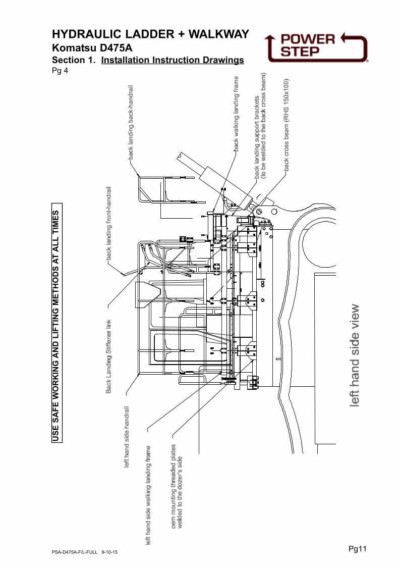
See 23626 - Platform:
1. Fit the Isolator Housings and Rear Isolator Brackets (fitted together as assemblies)
to the bolting pads on the back of the machine per View X and Detail W.
2. Fit the Rear Spreader Beam across the two assemblies in 'i' above per View X and
Detail W.
3. Fit Isolators to the bolting pad per View Y and Detail U.
4. Fit the Side Platform with all its' auxilary components so as to be supported by the
Rear Spreader Beam at the back and the Isolators at the front, per Views Y & Z
and Details U, V & W.
See 30264 - PROP:
1. Fit Clamp Beams and Clamps to the heavy roof plate of the ROPS, per Details Y &
Z.
2. Hold/clamp the Carrier Bars, already assembled with the PROP and Isolators to the
Clamp Beams so the PROP is central with the stowed ladder, per Detail Y. Tack
weld the Carrier Bars to the Clamp Beams.
3. Adjust the outer end of the PROP so it engages the ladder between the two top
treads (top in stowed position) by fitting/moving Isolator Spacers. Adjust the position
of the PROP so the ladder bears against it firmly when fully raised, by changing
which boltholes are used for the isolator pins.
4. Fully weld the Carrier Bars to the Clamp Beams, per Detail T.
NOTE
Follow all on-site/Mine lifting and safety procedures when installing
Power Step Landings to Dozer.

HYDRAULIC LADDER + WALKWAYKomatsu D475A
Section 1. Installation Instruction Drawings Bolting Pads 23 625
Pg4PSA-D475A-F/L-FULL 9-10-15
DE
TA
ILX
DE
TA
ILY
DE
TA
ILZ
DE
TA
ILW

Pg5PSA-D475A-F/L-FULL 9-10-15
HYDRAULIC LADDER + WALKWAYKomatsu D475A
Section 1. Installation Instruction Drawings Platform 23 626
VIE
W Y
VIE
W U
VIE
W V
VIE
W W
VIE
W X
VIE
W Z

Pg6PSA-D475A-F/L-FULL 9-10-15
HYDRAULIC LADDER + WALKWAYKomatsu D475A
Section 1. Installation Instruction Drawings Assembly 23 601

Pg7PSA-D475A-F/L-FULL 9-10-15
HYDRAULIC LADDER + WALKWAYKomatsu D475A
Section 1. Installation Instruction Drawings PROP P30 264
VIE
W Y
VIE
W V
VIE
W U
VIE
W Z VIE
W T
VIE
W X
VIE
W W

Pg8PSA-D475A-F/L-FULL 9-10-15
HYDRAULIC LADDER + WALKWAYKomatsu D475ASection 1. Installation Instruction DrawingsPg 1
Dwg PSA-K475-GB-Unit (5 Sheets)
US
E S
AF
E W
OR
KIN
G A
ND
LIF
TIN
G M
ET
HO
DS
AT
AL
LT
IME
S

Pg9PSA-D475A-F/L-FULL 9-10-15
HYDRAULIC LADDER + WALKWAYKomatsu D475ASection 1. Installation Instruction DrawingsPg 2
US
E S
AF
E W
OR
KIN
G A
ND
LIF
TIN
G M
ET
HO
DS
AT
AL
LT
IME
S

Pg10PSA-D475A-F/L-FULL 9-10-15
HYDRAULIC LADDER + WALKWAYKomatsu D475ASection 1. Installation Instruction DrawingsPg 3
US
E S
AF
E W
OR
KIN
G A
ND
LIF
TIN
G M
ET
HO
DS
AT
AL
LT
IME
S
Pg11PSA-D475A-F/L-FULL 9-10-15
HYDRAULIC LADDER + WALKWAYKomatsu D475ASection 1. Installation Instruction DrawingsPg 4
US
E S
AF
E W
OR
KIN
G A
ND
LIF
TIN
G M
ET
HO
DS
AT
AL
LT
IME
S

Pg12PSA-D475A-F/L-FULL 9-10-15
HYDRAULIC LADDER + WALKWAYKomatsu D475ASection 1. Installation Instruction DrawingsPg 5
US
E S
AF
E W
OR
KIN
G A
ND
LIF
TIN
G M
ET
HO
DS
AT
AL
LT
IME
S

HYDRAULIC LADDER + WALKWAYKomatsu D475A
Section 1. Installation Instruction Drawings - 23 615, 23 621, 23 623
Drive Arrangement
Pg13PSA-D475A-F/L-FULL 9-10-15
DR
IVE
AR
RA
NG
EM
EN
T

HYDRAULIC LADDER + WALKWAYKomatsu D475A
Section 1. Installation and Mounting Instructions (cont.)
Maintenance Notes
Pg14PSA-D475A-F/L-FULL 9-10-15
NOTE
Follow all on-site/Mine lifting and safety procedures when installing
Power Step Landings to Dozer.
WARNINGRaising the POWER STEP Landing by external means can create a vacuum in the
hydraulic cylinder and create the opportunity to allow air into the hydraulic system,
defeating the inherent safety features of the POWER STEP.
This must be avoided, to maintain safe operation of the POWER STEP.
In instances where the use of external means to raise the landing must be used,
please follow the following instructions:
Loosen hard plumbed hydraulic lines on cylinder side of lock valve on cylinder.
Raise landing by available means.
Note: Make necessary arrangements to collect displaced oil, and be aware that air enters
the piston side of the cylinder as landing is raised.
Lock in raised position.
Re-tighten hydraulic fittings.
SECURE THE LANDING IN THE RAISED POSITION, MECHANICALLY, CHAIN &
TAGOUT THE POWER STEP
To recommission the POWER STEP:
Loosen hydraulic fittings on cylinder side of lock valve.
Note: Collect displaced oil.
Lower landing to lowest position, using alternate safety approved means, fully retracting
cylinder. Ensure all personnel are clear of step radius.
Operate electrical control switch to purge air from the hydraulic line systems, lock valve
and cylinder.
Tighten the hydraulic fittings either side of lock valve to restriction fitting.
Cycle step unloaded several times to purge all air from hydraulic system.
The Power Step will not operate correctly if there is any air in the hydraulic circuit (due to
the incorrect operation of the lock valve).

HYDRAULIC LADDER + WALKWAYKomatsu D475A
Section 2. Electrical System - Wiring Diagram Pg 1
Pg15PSA-D475A-F/L-FULL 9-10-15
WIR
ING
HA
RN
ES
S

Pg16PSA-D475A-F/L-FULL 9-10-15
HYDRAULIC LADDER + WALKWAYKomatsu D475A
Section 2. Electrical System - Wiring Diagram Pg 2 Non Auto-Raise
Pg17PSA-D475A-F/L-FULL 9-10-15
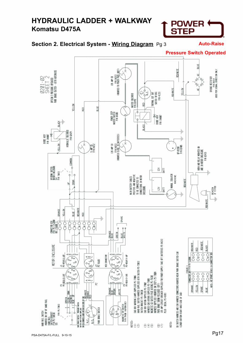
HYDRAULIC LADDER + WALKWAYKomatsu D475A
Section 2. Electrical System - Wiring Diagram Pg 3 Auto-Raise
Pressure Switch Operated
Pg18PSA-D475A-F/L-FULL 9-10-15
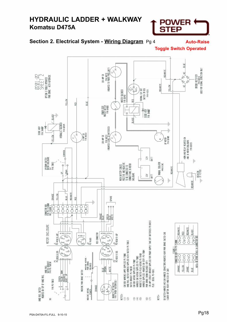
HYDRAULIC LADDER + WALKWAYKomatsu D475A
Section 2. Electrical System - Wiring Diagram Pg 4 Auto-Raise
Toggle Switch Operated

Pg19PSA-D475A-F/L-FULL 9-10-15
HYDRAULIC LADDER + WALKWAYKomatsu D475A
Section 2. Electrical System - Wiring Diagram Pg 5
WIRING HARNESS 1

Pg20PSA-D475A-F/L-FULL 9-10-15
HYDRAULIC LADDER + WALKWAYKomatsu D475A
Section 2. Electrical System - Wiring Diagram Pg 6
WIRING HARNESS 1

Daily
Visually check ladder and structure for damage, loose components,
handrails, etc.
Check for hydraulic oil leaks from hydraulic cylinders, plumbing and hoses.
Notify the appropriate supervisor for any observed damage or malfunction.
500 Hours
Grease the nipples on the rotation shaft and sector gears.
Check main mounting bolts for torque.
Check hydraulic oil level in power pack and top up as necessary. (Ladder in raised
position).
Top up using same hydraulic oil as used in hydraulics of machine.
Thoroughly check all electrical wiring for damage, replace as necessary.
Repeat daily check as above
5000 Hours
Change hydraulic oil in tank of hydraulic power pack (5.0 litres)
It is recommended that the same hydraulic oil be used in the power pack as the
hydraulics of the machine.
Grease 4 grease nipples on rotation shaft and sector gears, all of these are
accessible with the ladder lowered, and accessed from under the ladder.
Check and inspect all main bolts on ladder system.
Retorque if required.
Repeat daily check as above
HYDRAULIC LADDER + WALKWAYKomatsu D475A
Section 3. Recommended Maintenance Procedure
Pg21PSA-D475A-F/L-FULL 9-10-15
NOTE.THE RELIEF PRESSURE OF THE POWERPACK IS TO BE SET TO 2800PSI.
IF THE POWERPACK IS REPLACED,THIS RELIEF PRESSURE WILL NEED TO BE
RESET USING INLINE GAUGES.
FAILURE TO DO SO MAY RESULT IN ACCIDENT OR INJURY.

HYDRAULIC LADDER + WALKWAYKomatsu D475A
Section 4. Operating Procedure
Pg22PSA-D475A-F/L-FULL 9-10-15
To Lower Ladder (from the machine)
Position machine in a level, safe area, away from the work face, whenever possible.
Apply park brake and lower engine speed to idle.
Check that the area below the Ladder Access System is clear of people and
obstacles, and lower ladder by operating the two position electrical switch adjacent
to the ladder, to the down position by pressing the switch down.
Hold the switch in the down position until ladder is fully lowered.
If the Dozer is parked on uneven ground, the bottom of the ladder may touch the
ground before the ladder is in the fully lowered position.
Should this occur, descend the ladder with caution.
To Raise Ladder
Ascend the ladder onto the landing of the Dozer.
Ensure the area around the ladder is clear of people and standing to the side, clear
of the area the handrails and ladder raises into, operate the electrical switch to the
raise position (up).
Hold the switch in the up position until the ladder is in the fully raised position.
The ladder is now raised and stored.
OPERATING NOTES
NOTE: FLOW CONTROL VALVE ADJUSTMENT:
The valve should be positioned to restrict the flow and speed of the Power Step when
lowering. Adjust the knob on top of the valve by turning left or right (clockwise) when the
step is being lowered, until it is lowering at a safe and reasonable speed.
When it is adjusted, lock the adjusting knob by tightening the grub screw located on the
side of the knob.
NOTE: MAGNETIC 'GO' SWITCH ADJUSTMENT:
The switch target trigger area is located on the opposite side and end from the cable entry
point on the switch. Once it is mounted to the switch bracket, adjust the switch in or out
from the stair steel trigger point, to be within 3mm - 10mm from touching each other when
the stair is in the desired rest position.
[DO NOT EXCEED 10mm DISTANCE BETWEEN THE SWITCH AND STRIKER PLATE].
Test by raising and lowering the Power Step a couple of times and adjust again if
necessary.

HYDRAULIC LADDER + WALKWAYKomatsu D475A
Section 5. Assembly Complete PSA-D475A-FL
Pg23PSA-D475A-F/L-FULL 9-10-15

HYDRAULIC LADDER + WALKWAYKomatsu D475A
Section 5-1. RH Side Platform Assembly (PS-23613-A) [Includes Items 1, 2, 3A,B,C, 7, 8, 9, 10 (Qty. 3 only),11, 12, 13A,B, 18, 19, 20, 21, 22, 24,
28]
Pg24PSA-D475A-F/L-FULL 9-10-15

HYDRAULIC LADDER + WALKWAYKomatsu D475A
Section 5-1. RH Side Platform Assembly (PS-23613-A) See Drawing Page 24
Pg25PSA-D475A-F/L-FULL 9-10-15
Item Part No. Part Name Qty
1
2
3
3A
3B
3C
4
5
6
7
8
9
10
11
12
14
15
16
17
18
19
20
21
22
23
24
25
26
27
28
29
PS-23613
PS-23612
PS-K475LND-HR-B06
PS-KD475-23 614
PS-HRI-A04
PS-HRI-A06
PS-23604
PS-23603
PS-23602
PS-21941-02
PS-23616
PS-21941-06
PS-21930A
PS-21925
PS-21933B
PS-M20X60ZP
CPS-M16X40ZP
CPS-M16X25ZP
CPS-M12X35ZP
CPS-M12X65ZP
CPS-M12X75ZP
CPS-M12X35ZP
CPS-M12X25ZP
CPS-M8X35ZP
CPS-M20NZP
CPS-M12NZP
CPS-M8NN
CPS-M20WH
CPS-M16WH
CPS-M12WH
CPS-M8WH
SIDE PLATFORM
FLOOR PANEL
HANDRAIL REPLACEMENT FABRICATION
HANDRAILS- SIDE PLATFORM (Front only)
HANDRAIL POST-CLAMP ASSY
HANDRAIL POST - DOUBLE CLAMP ASSY.
REAR SPREADER BEAM
REAR ISOLATOR BRACKETS
ISOLATOR HOUSINGS
ANTI VIBRATION MOUNTING
PIVOT PIN BRACKET
RUBBER BUSH (Anti Vibration Mtg.)
ISOLATOR ASSEMBLY
MIDDLE BEARING MOUNTING
ISOLATOR BUSH PIN
BOLT-M20 x 60
BOLT-M16 x 40
BOLT-SOCKET HEAD-M16 x 25
BOLT-M12 x 120
BOLT-M12 x 65
BOLT-M12 x 75
BOLT-M12 x 35
BOLT-M12 x 25
BOLT-M8 x 35
NUT-M20
NUT-M12
NUT-NYLOC-M8
WASHER-HARDENED-M20
WASHER-HARDENED-M16
WASHER-HARDENED-M12
WASHER-HARDENED-M8
1
1
1
1
7
2
1
2
2
2
1
2
3
1
1
4
8
4
6
2
4
36
18
8
4
46
8
4
12
90
16

HYDRAULIC LADDER + WALKWAYKomatsu D475A
Section 5-2. Ladder & Handrail Assembly
Pg26PSA-D475A-F/L-FULL 9-10-15
Item Part No. Part Name Qty
1
2
3
4
5
5A
6
7
8
9
PS-22002
PS-23617
PS-21958
PS-21926-01
PS-21926-02
PS-21926-03
CPS-M12X45
CPS-M12X30
CPS-M12NZP
CPS-M12WH
LADDER & HANDRAIL FABRICATION
ROTATION SHAFT
PINION ASSY
LADDER SHAFT PIVOT BUSH-MIDDLE
LADDER SHAFT PIVOT BUSH (non drive end)
LADDER SHAFT PIVOT BUSH (drive end)
BOLT-M12 x 45
BOLT-M12 x 30
NUT-M12
WASHER-M12
1
1
1
1
1
1
8
8
16
32

FOLDING STAIRWAYKomatsu D475
Section 5-3. LH Side Platform Assembly (PS-K475LND- A03)See Parts List Page 28
Pg27PSA-D475A-F/L-FULL 9-10-15

FOLDING STAIRWAYKomatsu D475
Section 5-3. LH Side Platform Assembly (PS-K475LND-A03)See Drawing Page 27
Pg28PSA-D475A-F/L-FULL 9-10-15
Item Part No. Part Name Qty
1
2
3
4
5
6
7
8
9
10
11
12
13
PS-K475LND-B05
PS-K475LND-HR-B01
PS-K475LND-B02
PS-HRI-A04
PS-22789
CPS-M16X45
CPS-M16X40
CPS-M16X35
CPS-M12X35
CPS-M16NZP
CPS-M12NN
CPS-M16WH
CPS-M12WH
LANDING FABRICATION - LHS
HANDRAIL - LHS
MOUNTING BRACKET
POST CLAMP
RUBBER CONNECTOR-HANDRAILS
BOLT-M16 x 45
BOLT-M16 x 40
BOLT-M16 x 35
BOLT-M12 x 35
LOCKNUT-M16
NUT-NYLOC-M12
WASHER-M16
WASHER-M12
1
1
4
4
1
16
4
16
20
20
20
56
40

FOLDING STAIRWAYKomatsu D475
Section 5-4. Back Platform Assembly (PS-K475LND-A04)See Parts List Page 30
Pg29PSA-D475A-F/L-FULL 9-10-15

Pg30PSA-D475A-F/L-FULL 9-10-15
Item Part No. Part Name Qty
1
2
3
4
5
6
7
8
9
10
11
12
13
14
15
16
17
PS-K475LND-B06
PS-K475LND-HR-B02
PS-K475LND-HR-B03
PS-K475LND-B03
PS-K475LND-B04
PS-K475LND-B01
PS-K475LND-HR-B04
PS-K475LND-HR-B05
PS-HRI-A04
PS-22789
CPS-M16X45
CPS-M16X30
CPS-M12X35
CPS-M16NN
CPS-M12NN
CPS-M16WH
CPS-M12WH
WALKWAY FRAME FABRICATION - BACK
HANDRAIL - BACK - OUTER
HANDRAIL - BACK - INNER
WALKWAY BRACKET - LHS
WALKWAY BRACKET - CENTER
WALKWAY BRACKET- RHS
STIFFENER-LH
STIFFENER-RH
POST CLAMP
HANDRAIL RUBBER CONNECTION ASSY.
BOLT-M16 x 45
BOLT-M16 x 30
BOLT-M12 x 35
NUT-NYLOC-M16
NUT-NYLOC-M12
WASHER-M16
WASHER-M12
1
1
1
1
1
1
1
1
10
2
12
4
56
12
56
28
12
FOLDING STAIRWAYKomatsu D475
Section 5-4. Back Platform Assembly (PS-K475LND-A04)See Drawing Page 29

HYDRAULIC LADDER + WALKWAYKomatsu D475A
Section 5-5. Drive Unit Assembly
Pg31PSA-D475A-F/L-FULL 9-10-15

HYDRAULIC LADDER + WALKWAYKomatsu D475A
Section 5-5. Drive Unit AssemblySee Drawing Page 31
Pg32PSA-D475A-F/L-FULL 9-10-15
Item Part No. Part Name Qty
1
2
3
4
5
6
7
8
9
10
11
12
13
14
15
16
17
18
19
20
21
22
23
24
25
26
27
28
29
30
31
32
33
34
35
PS-63014
PS-23615
PS-23620
PS-23618
PS-21954A
PS-23619-02
PS-21106A
PS-61006-2
PS-21959-06
PS-21959-07
PS-21959-09
PS-21959-06
PS-21959-05
PS-21940-03
PS-23619-01
PS-M24X150ZP
CPS-M20X50ZP
CPS-M12X80ZP
CPS-M12X65ZP
CPS-M12X25ZP
CPS-M10X15ZP
CPS-M8X25
CPS-M5X15ZP
PS-M24NN
CPS-M20NZP
CPS-M12NZP
CPS-M12NN
CPS-M8NZP
CPS-M5NN
PS-M24WH
CPS-M20WH
CPS-M12WH
CPS-M10WH
CPS-M8WH
CPS-M5WH
HYDRAULIC CYLINDER
DRIVE MOUNTING FRAME
SECTOR GEAR
DRIVE GUARD
ACTUATOR CYL. MOUNTING ASSEMBLY
PROXIMITY SWITCH MOUNT BAR
PROXIMITY SWITCH MOUNT PLATE
GREASE NIPPLE M6 STR.
HUB SPACER RING
PIN SPACER RING
SECTOR GEAR BUSH
SECTOR GEAR HUB
CLAMP RING
KEEPER PLATE
SWITCH STRIKER
BOLT-M24 x 120
BOLT-M20 x 50
BOLT-M12 x 80
BOLT-M12 x 65
BOLT-M12 x 25
BOLT-M10 x 15
BOLT-M8 x 25
BOLT-M5 x 15
NUT-NYLOC-M24
NUT-M20
NUT-M12
NUT-NYLOC-M12
NUT-M8
NUT-NYLOC-M5
WASHER-HARDENED-M24
WASHER-HARDENED-M20
WASHER-HARDENED-M12
WASHER-HARDENED-M10
WASHER-HARDENED-M8
WASHER-HARDENED-M5
1
1
1
1
1
1
1
4
1
4
2
1
1
1
1
2
4
5
3
9
4
6
6
2
4
17
3
6
6
2
4
34
4
6
6

HYDRAULIC LADDER + WALKWAYKomatsu D475A
Section 5-6. PROP Assembly (PS-21945-A) Includes Items 1 to 13
Pg33PSA-D475A-F/L-FULL 9-10-15
Item Part No. Part Name Qty
1
2
3
4
5
6
7
8
9
10
11
12
13
PS-21945
PS-23622-01
PS-23622-02
PS-23622-03
PS-40003
PS-21930A
CPS-M12X120
CPS-M12X90ZP
CPS-M12X60ZP
CPS-M12X40ZP
CPS-M12NZP
CPS-M12NN
CPSM12WH
PROP
CARRIER BAR
CLAMP BEAM
ISOLATOR SPACER
BUFFER
ISOLATOR ASSEMBLY
BOLT-M12 x 120
BOLT-M12 x 90
BOLT-M12 x 60
BOLT-M12 x 40
NUT-M12
NUT-NYLOC-M12
WASHER-HARDENED-M12
1
2
3
6
4
4
4
6
4
8
14
6
22
Clamp Mounting 23622

HYDRAULIC LADDER + WALKWAYKomatsu D475
Section 5-7. Hydraulic Cylinder PS-63014-AH
Incl. Items 1A,1B,2,3,4,5,6,7,8,10,11,12.
Pg34PSA-D475A-F/L-FULL 9-10-15
Item Part No. Part Name Qty
1A
1B
1S
2
3
4
5
6
7
8
9
10
11
12
13
PS-63014A
PS-63014-P
PS-63011K
PS-63201
PS-61158-0.30
PS-61154
PS-61157
PS-61163
PS-61160
PS-61147
PS-60051-2.8
PS-61151
PS-61145
PS-61153
PS-60050-2.8
HYDRAULIC CYLINDER (INC. REDUCERS)
PIN - CYLINDER- (WITH RETAINER)
SEAL KIT (NOT SHOWN)
VALVE - PILOT OPERATED LOCKING
FITTING - RESTRICTION 90 DEG
FITTING - ELBOW- O RING 1/4BSPPx9/16”JIC
FITTING - O RING 1/4BSPPx 9/16”JIC
REDUCER JIC x BSPP
TUBE
FERRULES/NUTS 2 x each
HOSE- HYDR. (9/6”JIC SWIVEL FITTING 2.8M)
FITTING-ELBOW 7/16”JIC
FITTING-SWIVEL 9/16”JIC
FITTING-O RING 1/4”BSP x 7/16”JIC
HYDR. HOSE 7/16” SWIVEL FITTINGS
1
2
1
1
2
1
1
2
2
1
1
1
1
1
1

HYDRAULIC LADDER + WALKWAYKomatsu D475
Section 5-7. Hydraulics DiagramSee also Drawing page 34
Pg35PSA-D475A-F/L-FULL 9-10-15
0.030” 0.030”
Double Acting Hydraulic System with
directional Control Valve and Cylinder
Lock Valve

HYDRAULIC LADDER + WALKWAYKomatsu D475A
Section 5-8. Power Pack PS-80103A-SLDSee Parts List Pg 38
Pg36PSA-D475A-F/L-FULL 9-10-15
8
4
13
27
26 6 5 25
6
2 7
10
29
11
16
14
12
3 3024 3A
Hoses shown
dotted
View B View A
7A
9 9A 8A

HYDRAULIC LADDER + WALKWAYKomatsu D475A
Section 5-8. Power Pack PS-80103A-SLD
See Parts List Pg 38
Pg37PSA-D475A-F/L-FULL 9-10-15
NOTE.THE RELIEF PRESSURE OF THE POWERPACK IS TO BE SET TO 1500PSI.
IF THE POWERPACK IS REPLACED,THIS RELIEF PRESSURE WILL NEED TO BE
RESET USING INLINE GAUGES.
FAILURE TO DO SO MAY RESULT IN ACCIDENT OR INJURY
15
20
21
23
9
View B
9A
View A
32
33
24
14
19
11
16
28
10
18
31
17
12
BEACON
WORKLIGHT 3PIN
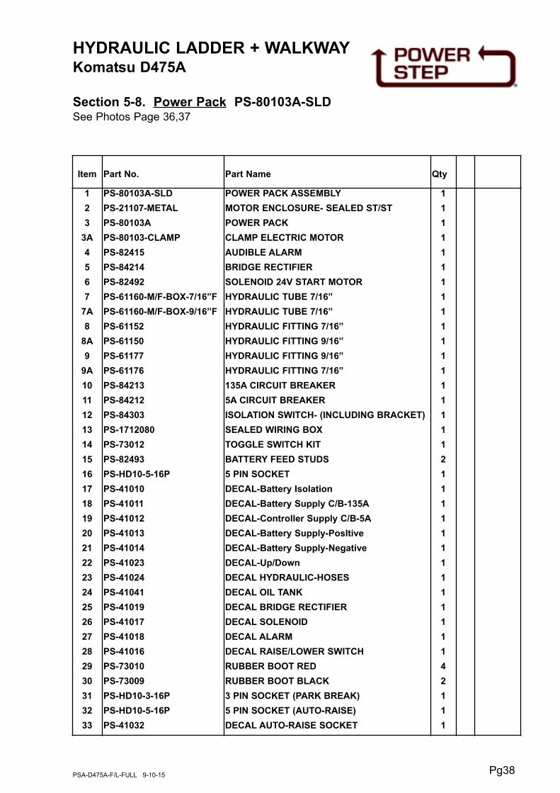
HYDRAULIC LADDER + WALKWAYKomatsu D475A
Section 5-8. Power Pack PS-80103A-SLDSee Photos Page 36,37
Pg38PSA-D475A-F/L-FULL 9-10-15
Item Part No. Part Name Qty
1
2
3
3A
4
5
6
7
7A
8
8A
9
9A
10
11
12
13
14
15
16
17
18
19
20
21
22
23
24
25
26
27
28
29
30
31
32
33
PS-80103A-SLD
PS-21107-METAL
PS-80103A
PS-80103-CLAMP
PS-82415
PS-84214
PS-82492
PS-61160-M/F-BOX-7/16”F
PS-61160-M/F-BOX-9/16”F
PS-61152
PS-61150
PS-61177
PS-61176
PS-84213
PS-84212
PS-84303
PS-1712080
PS-73012
PS-82493
PS-HD10-5-16P
PS-41010
PS-41011
PS-41012
PS-41013
PS-41014
PS-41023
PS-41024
PS-41041
PS-41019
PS-41017
PS-41018
PS-41016
PS-73010
PS-73009
PS-HD10-3-16P
PS-HD10-5-16P
PS-41032
POWER PACK ASSEMBLY
MOTOR ENCLOSURE- SEALED ST/ST
POWER PACK
CLAMP ELECTRIC MOTOR
AUDIBLE ALARM
BRIDGE RECTIFIER
SOLENOID 24V START MOTOR
HYDRAULIC TUBE 7/16”
HYDRAULIC TUBE 7/16”
HYDRAULIC FITTING 7/16”
HYDRAULIC FITTING 9/16”
HYDRAULIC FITTING 9/16”
HYDRAULIC FITTING 7/16”
135A CIRCUIT BREAKER
5A CIRCUIT BREAKER
ISOLATION SWITCH- (INCLUDING BRACKET)
SEALED WIRING BOX
TOGGLE SWITCH KIT
BATTERY FEED STUDS
5 PIN SOCKET
DECAL-Battery Isolation
DECAL-Battery Supply C/B-135A
DECAL-Controller Supply C/B-5A
DECAL-Battery Supply-PosItive
DECAL-Battery Supply-Negative
DECAL-Up/Down
DECAL HYDRAULIC-HOSES
DECAL OIL TANK
DECAL BRIDGE RECTIFIER
DECAL SOLENOID
DECAL ALARM
DECAL RAISE/LOWER SWITCH
RUBBER BOOT RED
RUBBER BOOT BLACK
3 PIN SOCKET (PARK BREAK)
5 PIN SOCKET (AUTO-RAISE)
DECAL AUTO-RAISE SOCKET
1
1
1
1
1
1
1
1
1
1
1
1
1
1
1
1
1
1
2
1
1
1
1
1
1
1
1
1
1
1
1
1
4
2
1
1
1

HYDRAULIC LADDER + WALKWAYKomatsu D475A
Section 5-9. Electrical Controls
Pg39PSA-D475A-F/L-FULL 9-10-15
Control Pendant SwitchMounted on Handrail
7 8
2
3
1
Cab Harness & Equipment
Refer Wiring Harness Drawings
Proximity Switch AssemblyMounted on Fixed Landing
45 6

HYDRAULIC LADDER + WALKWAYKomatsu D475A
Section 5-9. Electrical ControlsSee Photos Page 39
Pg40PSA-D475A-F/L-FULL 9-10-15
WARNING
LOW OR FAULTY BATTERIES WILL VOID
WARRANTY ON THE POWER PACK AND ALL
ELECTRICAL SWITCHES AND COMPONENTS
Item Part No. Part Name Qty
1
2
3
4
5
6
7
8
PS-73013
PS-73013-B
PS-77005
PS-77009AR
PS-77004
PS-75430
PS-77002
PS-77003
CONTROL PENDANT SWITCH
CONTROL PENDANT BRACKET
HAND RAIL SWITCH HARNESS
AUTO RAISE HARNESS
CABIN TO SWITCH HARNESS
PROXIMITY SWITCH
CABIN BOX LED LIGHT INDICATOR
WIRING HARNESS IN CABIN
1
1
1
1
1
2
1
1
Optional only
1 X Optional