PowerPoint Presentation - No Slide Titleesc.fsu.edu/documents/lectures/fall2006/EML4450L26.pdf•...
71
Sustainable Energy Science and Engineering Center Source: Marianne Salomon @ KTH Hydropower See the notes in Compedu http://www.energy.kth.se/compedu/webcompedu/index.html
Transcript of PowerPoint Presentation - No Slide Titleesc.fsu.edu/documents/lectures/fall2006/EML4450L26.pdf•...
Sustainable Energy Science and Engineering Center
Source: Marianne Salomon @ KTH
Hydropower
See the notes in Compedu
http://www.energy.kth.se/compedu/webcompedu/index.html

Sustainable Energy Science and Engineering Center
Global Renewable Energy
Source: IEA

Sustainable Energy Science and Engineering Center
Worldwide Hydropower
Source: IEA
Sustainable Energy Science and Engineering Center
Hydropower - History
• For many centuries, hydropower had been used to produced mechanical power to perform a range of activities, including grain milling, textile processing and other light industrial operations.
• A great part of the industrial revolution in the 18th century was “fueled” by access to hydropower
Sustainable Energy Science and Engineering Center
Hydropower Basics
• P (W) = ρ g H Q ηt
ρ = water density = 1000 kg/m3
g = gravitational const. = 9,81 m/s2
H = head (m)Q = water flow (m3/s)ηt = turbine efficiency

Sustainable Energy Science and Engineering Center
Hydropower Advantages
• A big advantage of hydroelectric power is the ability to quickly and readily vary the amount of power generated, depending on the load presented at that moment.
• It utilizes a renewable energy source as “fuel”(water)
• Generation process is environmentally clean• High reliability
Sustainable Energy Science and Engineering Center
Hydropower Disadvantages
• It requires large initial investments• Long transmission lines• Social and environmental impacts for large-scale
schemes
Sustainable Energy Science and Engineering Center
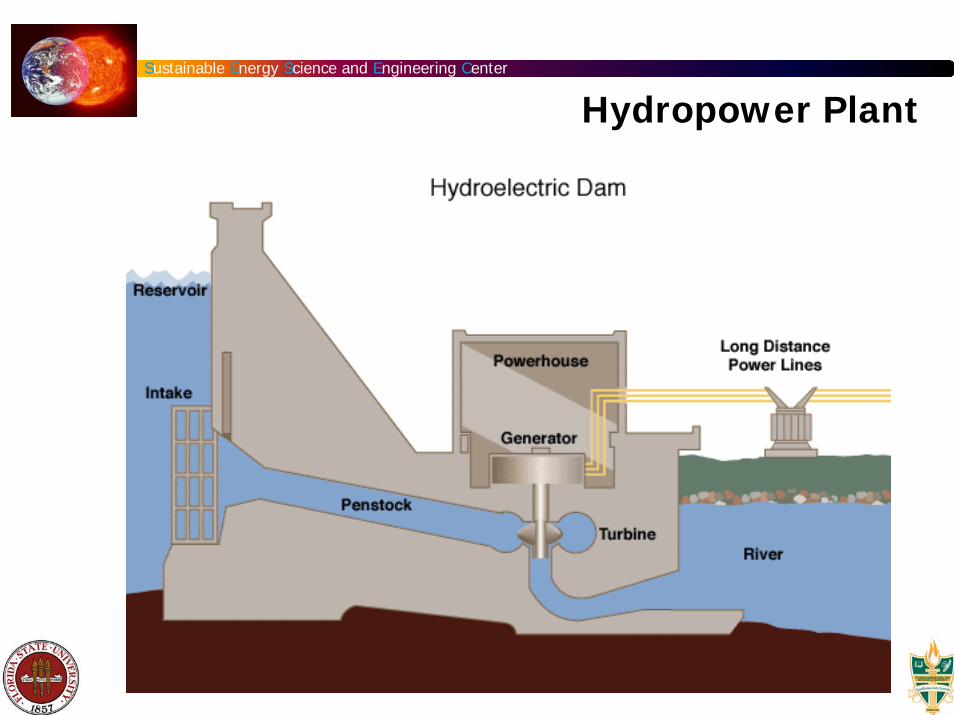
Hydropower Plant

Sustainable Energy Science and Engineering Center
Dams

Sustainable Energy Science and Engineering Center
Hydropower Plant
• Dam• Penstock• Spillway• Turbine• Powerhouse• Generator• Transformer• Transmission lines

Sustainable Energy Science and Engineering Center
Dams• Today there are over 45,000 dams (h>15 m, or V > 3 x 10⁶
m3 ) in > 150 nations.• About one fifth of the world's agricultural land is irrigated, and
irrigated agriculture accounts for about 40% of the world's agricultural production.
• One third of the countries in water-stressed regions of the world are expected to face severe water shortages this century. By 2025 there will be approximately 6.5 times as many people - a total of 3.5 billion - living in water-stressed countries.
• Half the world's large dams were built exclusively or primarily for irrigation, and an estimated 30 to 40% of the 271 million hectares of irrigated lands worldwide rely on dams.
• Dams are estimated to contribute to 12-16% of world food production.
• Hydropower currently provides 16% of the world's total electricity supply, and is used in over 150 countries with 24 ofthese countries depending on it for 90% of their supply.
Sustainable Energy Science and Engineering Center
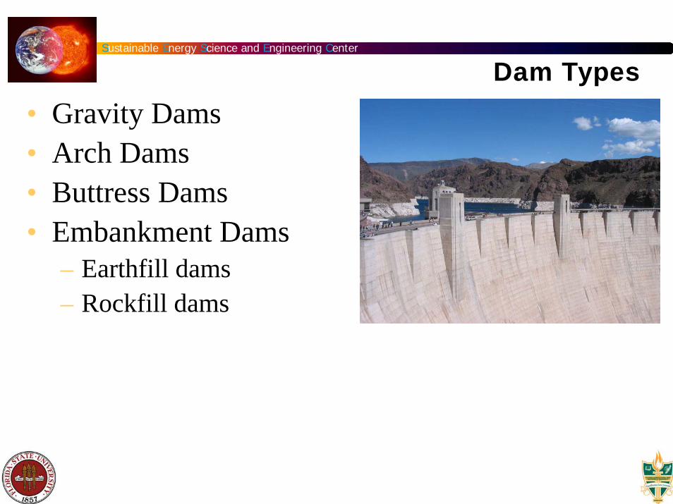
Dam Types
• Gravity Dams• Arch Dams• Buttress Dams• Embankment Dams
– Earthfill dams– Rockfill dams
Sustainable Energy Science and Engineering Center
Primary Embankment Dam Performance
• Freeboard • Erosion protection • Filter system • Dam foundation • Compaction • Drainage system • Geotechnical stability • Spillway function • Interaction dam body – dam foundation

Sustainable Energy Science and Engineering Center
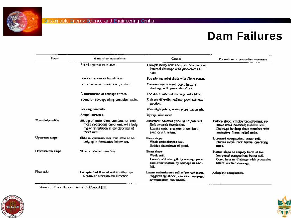
Dam Failures
Sustainable Energy Science and Engineering Center
Dam Failures

Sustainable Energy Science and Engineering Center
Dam Failures

Sustainable Energy Science and Engineering Center
Overtopping

Sustainable Energy Science and Engineering Center
Dam Failure
The reservoir behind the Teton Dam (Idaho, USA) was emptied within hours of the initial breach (1976)Source: U.S. Department of the Interior, Bureau of Reclamation
A large section of the upper reservoir failed, draining over 4 million m³ of water in twelve minutes Source: Federal Energy Regulatory Commission

Sustainable Energy Science and Engineering Center
Penstock
• The penstock is a pressurized-water conductor that extends from the free water surface at the reservoir, canal, or surge tank to the powerhouse.

Sustainable Energy Science and Engineering Center
Trash Racks
• A trash rack is required to protect the turbine runner from impinging objects.
• It is an structure made up of one or more panels, each generally fabricated of a series of evenly spaced parallel metal bars.
Sustainable Energy Science and Engineering Center
Spillways Types
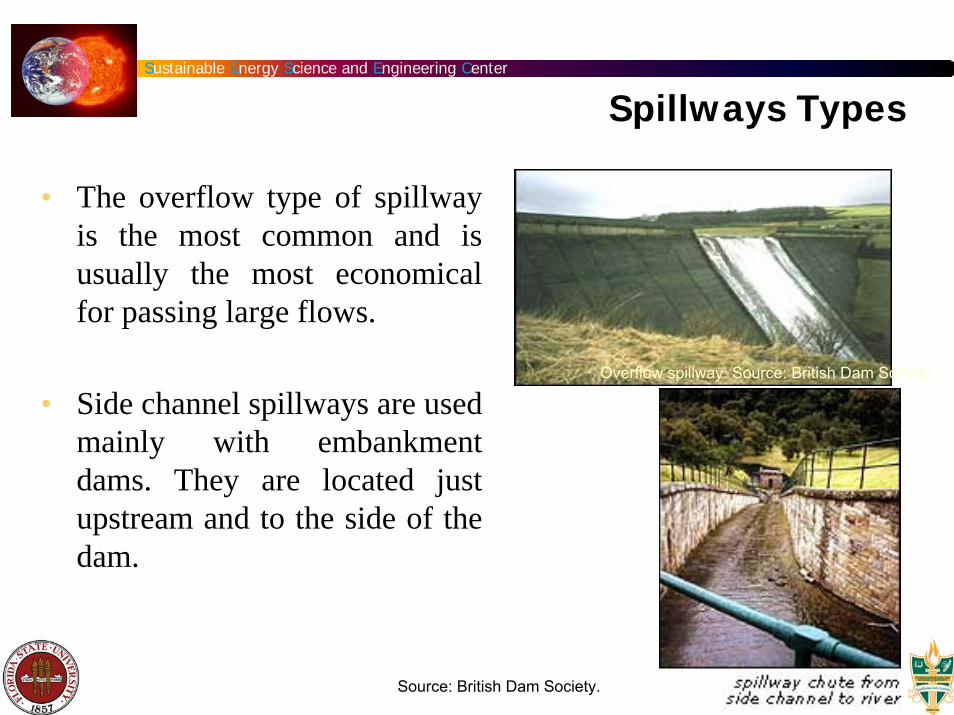
• The overflow type of spillway is the most common and is usually the most economical for passing large flows.
• Side channel spillways are used mainly with embankment dams. They are located just upstream and to the side of the dam.
Overflow spillway. Source: British Dam Society.
Source: British Dam Society.

Sustainable Energy Science and Engineering Center
Spillway Types • A shaft spillway is sometimes
called a "morning glory" spillway. It is a hollow tower or shaft, usually circular, which has a funnel at its top. The tower sits in the reservoir near the dam.
• The tower sits above an outlet pipe or tunnel used to transport water out of the reservoir. It is built to house controls for opening and closing valves or gates that control the flow of water through the outlet.
Source: British Dam Society.
Source: British Dam Society.
Sustainable Energy Science and Engineering Center
Spillways Types
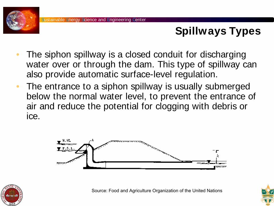
• The siphon spillway is a closed conduit for discharging water over or through the dam. This type of spillway can also provide automatic surface-level regulation.
• The entrance to a siphon spillway is usually submerged below the normal water level, to prevent the entrance of air and reduce the potential for clogging with debris or ice.
Source: Food and Agriculture Organization of the United Nations

Sustainable Energy Science and Engineering Center
Canals
• A power canal conveys water from the reservoir to the turbine intake structure. In some cases, the canal conveys water to a forebay upstream of the turbine intake.
Source: Ritter, Michael E. The Physical Environment: an Introduction to Physical Geography. 2006

Sustainable Energy Science and Engineering Center
Tunnels
• The layout of a hydroelectric plant sometimes requires carrying the water through mountains, requiring the use of tunnels. These tunnels may operate under pressure or flow partly full.
Kárahnjúkar power station (Iceland)Source: www.tunnels.mottmac.com/
Source: Standard Handbook of PowerplantEngineering. Elliot, T. et al. 1997

Sustainable Energy Science and Engineering Center
Surge Tanks
• Its purpose is to relieve the excessive pressures resulting from the manipulation of the turbine gates as the load on the generating unit varies, and to supply initial water for an increasing load while the water in the tunnel is being accelerated.
Source: Standard Handbook of Powerplant Engineering. Elliot, T. et al. 1997
Sustainable Energy Science and Engineering Center
Tailrace
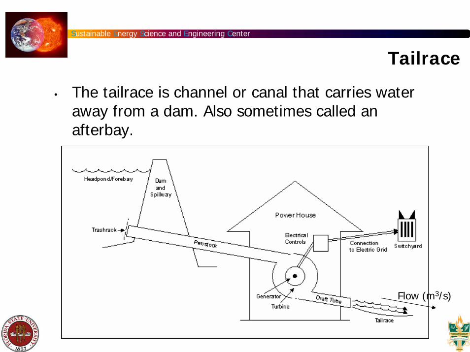
• The tailrace is channel or canal that carries water away from a dam. Also sometimes called an afterbay.
Tail race tunnel at Stornorrfors
Flow (m3/s)

Sustainable Energy Science and Engineering Center
Draft Tube• A water conduit which carries water from a
reaction turbine runner to the tailrace. It is designed to maximize head utilization by the turbine.

Sustainable Energy Science and Engineering Center
Fish Passages
• It is an structure consisting e.g. of a series of overflow weirs which are arranged in steps that rise about 30 cm (width varies from 1.2 m to 2.4 m and lengths varying between 1.8 and 3.0 m) and serve as a means for allowing migrant fish to travel upstream past a dam or weir.
John Day Dam fish ladder, Columbia River
Source: United States Army Corps of Engineers.

Sustainable Energy Science and Engineering Center
Turbines
Sustainable Energy Science and Engineering Center
Water Wheels
• Water wheels have been used for thousands of years for industrial power. Their main shortcoming is size, which limits the flow rate and head that can be harnessed.
• The migration from water wheels to modern turbines occurred during the Industrial revolution

Sustainable Energy Science and Engineering Center
Water Wheels
• The main difference between early water turbines and water wheels is a swirl component of the water which passes energy to a spinning rotor.
The Orontes River water wheels in Hama, Syria
Sustainable Energy Science and Engineering Center
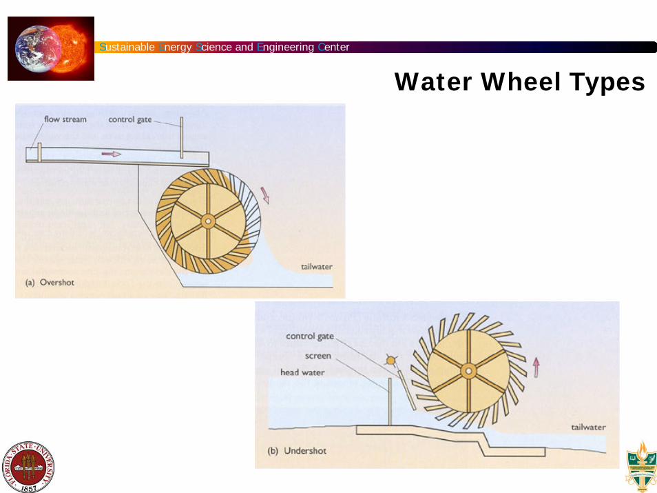
Water Wheel Types

Sustainable Energy Science and Engineering Center
Water Wheel Types
Sustainable Energy Science and Engineering Center
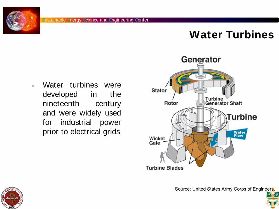
Water Turbines
• Water turbines were developed in the nineteenth century and were widely used for industrial power prior to electrical grids
Source: United States Army Corps of Engineers.

Sustainable Energy Science and Engineering Center
Main Design Parameters
• The power capacity of a hydropower plant is primarily a function of two main variables of the water:
• water flow• the hydraulic head

Sustainable Energy Science and Engineering Center
Flow Duration Curve
Source: European Small Hydropower Association

Sustainable Energy Science and Engineering Center
Design Flow
• Design flow is the maximum flow for which your hydro system is designed.
• It will likely be less than the maximum flow of the stream (especially during the rainy season), more than the minimum flow, and a compromise between potential electrical output and system cost.

Sustainable Energy Science and Engineering Center
Design Flow
• If a system is to be independent of any other energy or utility backup, the design flow should be the flow that is available 95 percent of the time or more.
• Therefore, a stand-alone system such as a micro-hydropower system should be designed according to the flow that is available year-round; this is usually the flow during the dry season.

Sustainable Energy Science and Engineering Center
Some flow definitions
• Reserved flow: it is the minimum flow required to avoid aquatic life damage in the water stream
• Firm flow: The firm flow is defined as the flow being available X % of the time, where X is a percentage specified by the user and usually equal to 95%.
Sustainable Energy Science and Engineering Center
Hydraulic Head
• GROSS HEAD of a hydropower facility is the difference between headwater elevation and tailwater elevation.
• NET HEAD is the effective head on the turbine and is equal to the gross head minus the hydraulic losses before entrance to the turbine and outlet losses

Sustainable Energy Science and Engineering Center
Net Head
tailwater

Sustainable Energy Science and Engineering Center
Hydraulic Losses
• Friction losses • Intake losses• Trash racks losses• Transitions losses
Sustainable Energy Science and Engineering Center
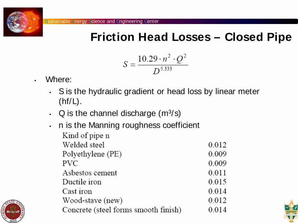
Friction Head Losses – Closed Pipe
• Where: • S is the hydraulic gradient or head loss by linear meter
(hf/L). • Q is the channel discharge (m3/s)• n is the Manning roughness coefficient

Sustainable Energy Science and Engineering Center
Friction Head Losses – Open Channel
• Where:• S is the hydraulic gradient or head loss by linear meter
(hf/L). • Q is the channel discharge (m3/s)• P is the wetted perimeter (m)• A is cross-sectional area of the pipe (m2), and• n is the Manning roughness coefficient

Sustainable Energy Science and Engineering Center
Wetted Perimeter
• The wet perimeter is as it sounds, the perimeter of the cross sectional area that is "wet".
• For the figure shown P= a+b+c+d

Sustainable Energy Science and Engineering Center
Trash rack losses
Source: European Small Hydropower Association
Sustainable Energy Science and Engineering Center
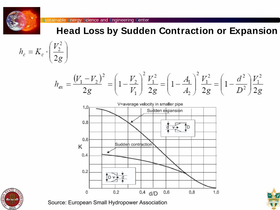
Head Loss by Sudden Contraction or Expansion
Source: European Small Hydropower Association
Sustainable Energy Science and Engineering Center
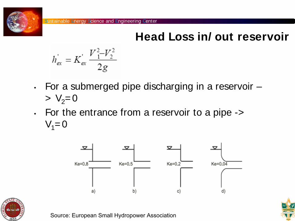
Head Loss in/out reservoir
• For a submerged pipe discharging in a reservoir –> V2=0
• For the entrance from a reservoir to a pipe -> V1=0
Source: European Small Hydropower Association

Sustainable Energy Science and Engineering Center
Turbine Selection

Sustainable Energy Science and Engineering Center
Turbine Efficiency
Source: Paish, O.;2002. Small hydro power: technology and current status. Renewable and Sustainable Energy Reviews, Vol 6 pp. 537–556

Sustainable Energy Science and Engineering Center
Turbines: Specific Speed
• The specific speed of a turbine (ns) can be defined as the speed of an ideal, geometrically similar turbine, which yields one unit of power for one unit of head
• The specific speed of a turbine is given by the manufacturer and will always refer to the point of maximum efficiency
Source: Layman's Guidbook on how to develop a small hydro site

Sustainable Energy Science and Engineering Center
Specific Speed vs. Head

Sustainable Energy Science and Engineering Center
Powerhouses
• The powerhouses contain the turbine, generator, control equipment, transformers and supporting auxiliary equipment.
• Below the turbines are the draft tubes and their gates
• Types of powerhouses:• Integral intake powerhouse• Conventional surface powerhouse• Underground powerhouse

Sustainable Energy Science and Engineering Center
Integral Intake Powerhouse
Source: Standard Handbook of Powerplant Engineering. Elliot, T. et al. 1997

Sustainable Energy Science and Engineering Center
Conventional Surface Powerhouse
Source: Standard Handbook of Powerplant Engineering. Elliot, T. et al. 1997

Sustainable Energy Science and Engineering Center
Underground Powerhouses
Source: Standard Handbook of Powerplant Engineering. Elliot, T. et al. 1997

Sustainable Energy Science and Engineering Center
Electrical Components
• Generator• Transformer• Transmission Lines

Sustainable Energy Science and Engineering Center
Small–Scale Hydropower Plants
• P ≤ 10 MW (is the most widely accepted value worldwide)
• More environmental friendly • Contribute to development of rural and poor
regions.• Reduction of greenhouse gas emissions (1 GWh
electricity = reduction 480 tons of CO2)

Sustainable Energy Science and Engineering Center
Small-Scale Hydropower Plants
• Small hydro (≤10 MW) contributed with over 40 GW of world capacity (2002)
• Installed capacity of about 8 GW (2002) in Europe*.
• In China**, the estimated installed capacity is over 26 GW (2002)
• Global small hydro potential is believed to be in excess of 100 GW.
*Defined as ≤ 10 MW** Defined as ≤ 25 MW
Sustainable Energy Science and Engineering Center
Social & Environmental Impacts
• Population displacement• Loss of social networks and changing way of living• Noise pollution is negligible • CO2 free electricity production (for the power generation
process only)• Provision of water and sanitation services• Dams can facilitate development of diseases
Sustainable Energy Science and Engineering Center
Environmental Impacts
• Visual impact• Diversion of mountain streams• Blockage of fish passage both upstream and
downstream • Storing water in reservoir may reduce the final
flow as a result of evaporation• Reduction in the flow of soil and nutrients

Sustainable Energy Science and Engineering Center
Environmental Impacts
• Pollution is stored in the reservoir• Possible dam failure • Loss of cultural heritage• local increase in water vapor and some
temperature effects• Vegetation rotting under water produces methane
-> emissions from northern reservoirs are typically about 5% of conventional power plants, while emissions from tropical reservoirs are typically 25%

Sustainable Energy Science and Engineering Center
Environmental Impacts
• High levels of total dissolved gas causes bubble disease in aquatic organisms and can lead to their death
• Erosion of riverbed• Water turbidity • Eutrophication• Supersaturation

Sustainable Energy Science and Engineering Center
Environmental Impacts

Sustainable Energy Science and Engineering Center
Environmental Impacts

Sustainable Energy Science and Engineering Center
Three Gorges Dam• Type: Concrete Gravity Dam• Cost: Official cost $25bn - actual
cost believed to be much higher• Work began: 1993• Due for completion: 2009• Power generation: 26 turbines
on left and right sides of dam. Six underground turbines planned for 2010
• Power capacity: 18 GW • Reservoir: 660km long,
submerging 632 sq km of land. When fully flooded, water will be 175m above sea level
• Navigation: Two-way lock system became operational in 2004. One-step ship elevator due to open in 2009.
• Dam:185m high, 2,309m • Electricity production: 3% of
the electricity production capacity in 2006
Source: BBC, 2006

Sustainable Energy Science and Engineering Center
Three Gorges Dam
• 18 GW of electricity capacity installed that will generate the equivalent of roughly 18 coal power stations or 11,000 barrels of oil per hour
• The dam could potentially reduce China's annual coal consumption by 40 to 50 million tons
• This will reduce the discharge of 2 million tons of sulfur dioxide and 10,000 tons of carbon monoxide per year

Sustainable Energy Science and Engineering Center
Three Gorges Dam example
• The primary aims of the dam are to alleviate flooding on the Yangtze River and generate power.
• At least 1 million people are being relocated to make way for the project.
• More than 1,200 towns and villages will disappear under its rising waters
• Those made homeless by the dam are being moved to new townships.
Source: BBC, 2006

Sustainable Energy Science and Engineering Center
Three Gorges Dam
• The 600 km long reservoir will inundate some 1,300 archeological sites and alter the legendary beauty of the Three Gorges
• Despite the amount of effort that has gone into the dam, critics are sceptical that it will adequately control flooding and say silting may eventually clog up its turbines.
A billboard in the port of Wushanshows the height that the water will reach, ultimately submerging all of its wharf facilities.
Source: BBC, 2006

Sustainable Energy Science and Engineering Center
Three Gorges Dam
• The reservoir behind the dam is already polluted
• There are two hazards uniquely identified with the dam:
• sedimentation modeling is unverified
• the dam sits on a seismic fault