![StaticsC02 24092013 [Uyumluluk Modu] - ITUweb.itu.edu.tr/~ustunda1/course/StaticsC02_24092013.pdf · – Resultant force is shown by the diagonal of the ... 2.4 Addition of a System](https://static.fdocuments.in/doc/165x107/5b7f523e7f8b9ad9778bee5f/staticsc02-24092013-uyumluluk-modu-ustunda1coursestaticsc0224092013pdf.jpg)
PowerPoint Images - ITUweb.itu.edu.tr/~halit/Makel/ch13_m.pdf · of the pitch diameter to the...
29
PowerPoint Images Chapter 13 Gears - General Mechanical Engineering Design Seventh Edition Shigley • Mischke • Budynas Copyright © The McGraw-Hill Companies, Inc. Permission required for reproduction or display.
Transcript of PowerPoint Images - ITUweb.itu.edu.tr/~halit/Makel/ch13_m.pdf · of the pitch diameter to the...

PowerPoint Images
Chapter 13
Gears - General
Mechanical Engineering Design
Seventh Edition
Shigley • Mischke • Budynas
Copyright © The McGraw-Hill Companies, Inc. Permission required for reproduction or display.

Fig. 13.1 Spur gears have teeths parallel
to the axis of rotation. They are used to
transmit motion from one shaft to another,
parallel, shaft.
Fig. 13.2 Helical gears have teeth inclined to
the axis of rotation. Sometimes helical gears
are used to transmit motion between
nonparallel shafts.
Types of Gears

Fig. 13.3 Bevel gears have teeth formed on
conical surfaces and are used mostly for
transmitting motion between intersecting
shafts.
Fig. 13.4 Hypoid gears, worm gear are used to
transmit motion between nonparallel,
nonintersecting shafts.

Fig. 13.5 Nomenclature. The circular pitch, p, is the distance, measured on the pitch circle, measured
from a point on one tooth to a corresponding point on an adjacent point. The module, m, is the ratio
of the pitch diameter to the number of teeth. The diametral pitch, P, is the ratio of the number of teeth
on the gear to the pitch diameter. The addendum, a, is the radial distance between the top land and
the pitch circle. The dedendum, b, is the radial distance from the bottom land to the pitch circle. The
clerance circle is a circle that is tangent to the addendum circle of the mating gear.
P=N/d
p=πd/N= πm
m=d/N
Nomenclature

Fig. 13.7 (a) Generation of an involute;
(b) involute action
Tooth Systems, Conjugate Action, Involute Properties
A tooth system is a standard which specifies the relationships involving addendum,
dedendum, working depth, tooth thickness, and pressure angle.
When the tooth profiles are designed so as to produce a constant angular velocity ratio
during meshing, these are said to have conjugate action. The involute profile is used
to obtain the conjugate action.
Fig. 13.8 Construction of an involute
curve

Fig. 13.12 Tooth action.

Fig. 13.17 Generating a spur gear with a pinion
cutter.
The Forming of Gear Teeth
There are a large number of ways of forming of the teeth of gears, such as sand casting, shell
Molding, investment casting, permanent-mold casting, die casting, and centrifugal casting. Teeth can
be formed by using the powder-metallurgy process; or by using extrusion. Gears which carry large
loads in comparison with their size are usually made of steel and are cut with either form cutters or
generating cutters.
Fig. 13.18 Shaping teeth with a rack.

Fig. 13.19 Hobbing a worm gear.
The hob is simply a cutting tool which is shaped like a worm.

Choose an appropriate module, m (use fatigue, fracture mechanics, strength of materials
relations, and standard sizes).
Calculate addendum and dedendum (a=1.m b=1.2 ~ 1.25 m)
Calculate the pitch diameter, d, and the diameters of addendum and dedendum circles, da and db.
(d=N.m da=d+2.a db=d-2.5 m)
Calculate the distance between the axes ((dP+dG)/2 = m(NP+NG)/2).
Calculate the face width, F=Fw.p=Fw.π.m.

Fig. 13.20 Terminology of bevel gears.
tanγ=NP/NG
tanГ=NG/NP
Straight Bevel Gears
2 brNp

Fig. 13.22 Nomenclature of helical gears.
Parallel Helical Gears
cosn tp p
tan
tx
pp
n np m cosn tm m
tancos
tan
n
t
cos
NN
Fig. 13.23 A cylinder cut by an
oblique plane.

Fig. 13.24 Nomenclature of a single-
enveloping worm gearset.
dG=NGpt/π
L=pxNW
tanλ=L/ πdW
C0.875/3≤dW ≤ C0.875/1.7
C : center distance
Worm Gears

n3=|N2/N3|n2=|d2/d3|n2
n6=(N2/N3) (N3/N4) (N5/N6)n2
e=product of driving tooth numbers / product of driven tooth numbers, nL=enF
Fig. 13.27 Gear trains. Gear 3 is an idler. 2,3,5 are drivers. 3,4,6 are driven members.
Gear Trains

Fig. 13.26 Thrust, rotation, and hand relations for crossed helical gears.

Fig. 13.28 Planetary, or epicyclic, gear trains. Some of the gear axes rotate about others.
e=(nL-nA)/(nF-nA)

Fig. 13.29

Fig. 13.35
Force analysis
Wt=T/rav
Wr=WttanΦcosγ
Wa=WttanΦsinγ

Fig. 13.37
T1=Wtd1/2
Spur gears
Wr=W.sinΦt
Wt=W.cosΦt
Helical gears
Wr=W.sinΦn
Wt=W.cosΦn.cosψ
Wa=W.cosΦn.sinψ

Fig. 13.40
Wx=WcosΦnsinλ
Wy=WsinΦn
Wz=WcosΦncosλ
WWt=-WGa=Wx
WWr=-WGr=Wy
WWa=-WGt=Wz
Efficiency
η=(cosΦn-ftanλ)/(cosΦn+fcotλ)
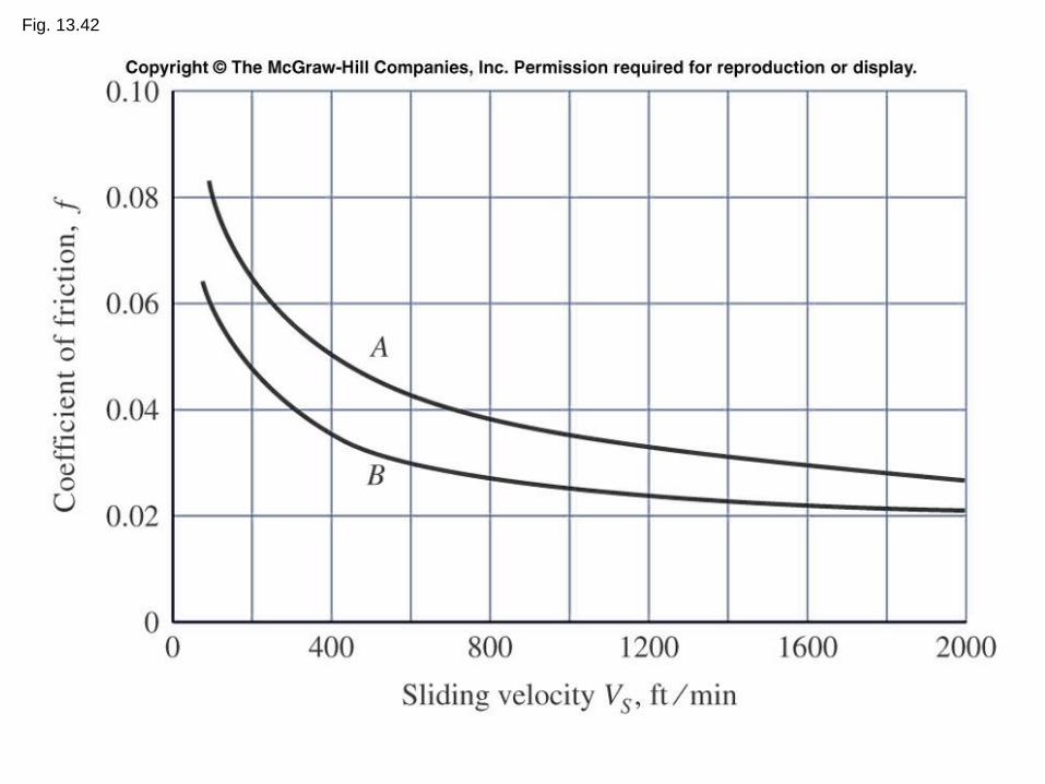
Fig. 13.42

Chapter 13, Problem 2.
A 15-tooth spur pinion has a module of 3 mm and runs at a speed of 1600 rev/min.
The driven gear has 60 teeth. Find the speed of the driven gear, the circular pitch,
and the theoretical center-to-center distance.
Chapter 13, Problem 13.
A parallel-shaft gearset consists of an 18-tooth helical pinion driving a 32-tooth
gear. The pinion has a left-hand helix angle of 25, a normal pressure angle of
20, and a normal module of 3 mm. Find:
(a) The normal, transverse, and axial circular pitches
(b) The transverse module and the transverse pressure angle
(c) The pitch diameters of the two gears

Chapter 13, Problem 16.
The mechanism train shown consists of an assortment of gears and pulleys to
drive gear 9. Pulley 2 rotates at 1200 rev/min in the direction shown. Determine
the speed and direction of rotation of gear 9.
Figure P13-16

Chapter 13, Problem 21 (Chapter 13, Problem 21).
Tooth numbers for the gear train shown in the figure are N2 = 12, N3 = 16, and
N4 = 12. How many teeth must internal gear 5 have? Suppose gear 5 is fixed.
What is the speed of the arm if shaft a rotates counterclockwise at 320 rev/min?
Figure P13-21

Chapter 13, Problem 24 (Chapter 13, Problem 25).
The epicycle train shown in the figure has the arm attached to shaft a, and sun
gear 2 to shaft b. Gear 5, with 111 teeth, is an internal gear and is part of the
frame. The two planets, gears 3 and 4, are both fixed to the same planet shaft. If
this train is used as an in-line speed reducer, which is the input shaft, a or b? Will
both shafts then rotate in the same or in the opposite directions?
Figure P13-24