PowerNavigator User Guide for Digital Multiphase · – Project files for all Digital Multiphase...
67
PowerNavigator 5.3 Digital Multiphase User Guide October, 2016
Transcript of PowerNavigator User Guide for Digital Multiphase · – Project files for all Digital Multiphase...

PowerNavigator 5.3Digital Multiphase User Guide
October, 2016

Overview
• This guide walks a user through the steps to setup and configure the ISL691xx and ISL681xx Digital Multiphase products using the PowerNavigator GUI. For all other Intersil Digital Power devices, please see the Digital Point of Load user guide.
• This guide is intended for use with PowerNavigator Revision 5.3.45
• This presentation contains the following sections that can be referred to depending on the stage of the design:– PowerNavigator Introduction– Running PowerNavigator– Creating a new project in offline mode– Connecting to Hardware and loading Project files– Creating HEX files for production programming

Installing PowerNavigator

• Download the latest version of PowerNavigator from:
www.intersil.com/powernavigator
• PowerNavigator Requires a Windows PC with Win7 or greater
• A driver is NOT required for the USB to PMBus adapter – it uses the built-in Windows HID driver.
Installing PowerNavigator

Installing PowerNavigator
Double Click installer to begin install process.
Click through PowerNavigator Setup Wizard to install.
After installation is complete, PowerNavigator will be visible in
Start Menu under “Intersil”1 2 3

Launching PowerNavigator

Intersil PowerNavigator Launch Screen
Intersil Confidential Information

Digital Multiphase – PowerNavigator Launch Screen
Intersil Confidential Information
Connected Devices Offline Mode Project Load
Connected Devices:- Used for telemetry monitoring only. Device configuration changes cannot be made in this mode.
Offline Mode:- Used to create new projects
Project Load:- Used to load an existing project or connect to existing hardware. Allows device configuration changes to be made.

• Digital multiphase devices rely on Project Files for loading and editing configuration settings. It is not possible to read back the stored configuration settings from a multiphase controller, so proper use and maintenance of project files is critical.
• Definitions:– Project File: System level file that contains all project information, including individual
configuration files.– Config File: Unique file contained within the project file with the setup information for a single
controller configuration
• The project files can be found on your PC:– C:\USERS\User Name\Documents\Intersil\PowerNavigator\Projects– Project files for all Digital Multiphase demo boards are available from Intersil upon request
Project Files

Creating a New Project File in Offline ModeISL681xx General Purpose Controllers

Digital Multiphase – PowerNavigator Launch Screen
Intersil Confidential Information
Connected Devices Offline Mode Project Load
Click on “Build New System” and then
“Start”

Digital Multiphase – PowerNavigator Main Screen
Intersil Confidential Information
Expand Digital Multiphase section in GUI

Digital Multiphase – PowerNavigator Main Screen
Intersil Confidential Information
1. Grab any device or label and drag and drop into the PowerMap
2. Drop onto any node identified by a black square.

Digital Multiphase – PowerNavigator PowerMap
Intersil Confidential Information
Each box or “Rail Block” on the PowerMap represents one of the device outputs
Double Click on the Rail Block to bring up the device’s design tool.
Output 1
Output 0

Digital Multiphase - PowerMap Rail Block Overview
Intersil Confidential Information
Example ISL68137 RailBlock (6-PH operation):
Controller TypeNumber of phases assigned. 6PH in this example – each “dot” represents a phase.
Address and Page info
PMBus Enable/ Disable
PGOOD Status
Rail Name (customizable)Vout/Iout Telemetry
Online (hardware connected) or Offline indicator
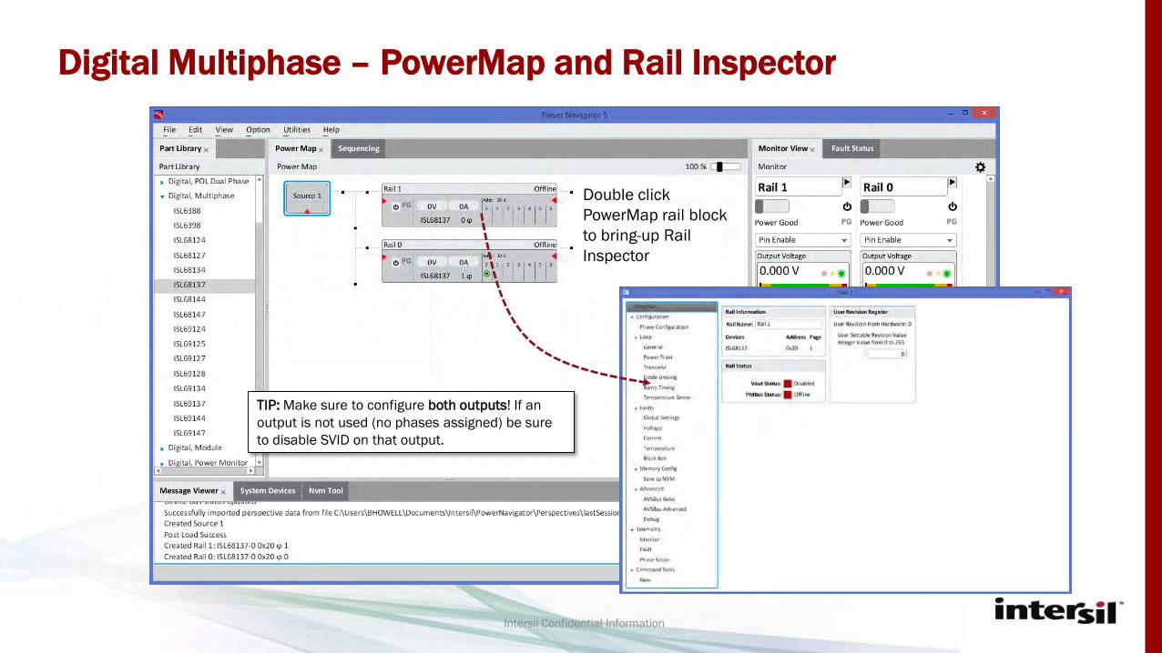
Digital Multiphase – PowerMap and Rail Inspector
Intersil Confidential Information
Double click PowerMap rail block to bring-up Rail Inspector
TIP: Make sure to configure both outputs! If an output is not used (no phases assigned) be sure to disable SVID on that output.

Digital Multiphase – PowerNavigator Rail Inspector
Intersil Confidential Information
Overview Screen Shows:- Rail Name- Device Type- Device PMBus Address- Rails Status
- Enabled/Disabled- PMBus connected or
Offline
Rail Inspector
Navigation panel
Revision Register – user settable configuration revision to assist with revision tracking
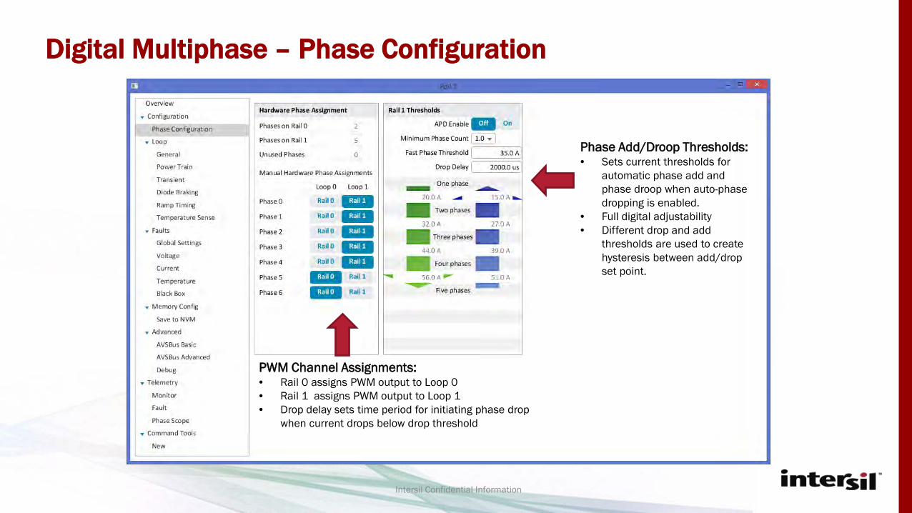
Digital Multiphase – Phase Configuration
Intersil Confidential Information
PWM Channel Assignments:• Rail 0 assigns PWM output to Loop 0• Rail 1 assigns PWM output to Loop 1• Drop delay sets time period for initiating phase drop
when current drops below drop threshold
Phase Add/Droop Thresholds:• Sets current thresholds for
automatic phase add and phase droop when auto-phase dropping is enabled.
• Full digital adjustability• Different drop and add
thresholds are used to create hysteresis between add/drop set point.

Digital Multiphase – Device Setup
Intersil Confidential Information
Vout and Vout OV/UV fault limits thresholds
Per phase switching frequency
VOUT_MAX sets upper lime of output voltage. Any VOUT_COMMAND above VOUT_MAX will be ignored.
Check “track PMBus Vout” to have fault levels track the Vout command based on percentage

Digital Multiphase – Power Train Configuration
Intersil Confidential Information
Selects current sense scheme –Inductor DCR or SPS.
Bulk Capacitance or ceramic capacitance by output inductors
Ceramic Capacitance used at load
Displays max current measurement per phase before Isense ADC clips
Default IMON output for ISL99226/7 SPS. Adjust as needed to dial in load line accuracy
Output inductance and DCR (per phase). Use typical values from inductor datasheet. This information is REQUIRED for proper operation.
Approx. resistance of PCB planes between output inductors and Load.
Power stage UFET and LFET Reds(on). Use typical values from datasheet.

Digital Multiphase – Control Loop Configuration
Intersil Confidential Information
Proportional Gain Knobs. Higher gain increases loop BW, improving transient performance
Filter to reduce High Frequency Jitter in P-gain path
Integral Gain block.
Pulse Advance setup
TIP: Default P and I settings can be used for initial board bring-up, then dialed in during transient testing.
Digitally adjustable load line setting
CONTACT INTERSIL FOR TUNING GUIDE WITH MORE INFO

Digital Multiphase – Diode Braking (Load Release Improvement)
Intersil Confidential Information
Enabled/Disabled Diode Braking
TIP: Diode braking should only be enabled after other loop settings have been optimized.
Settings to determine when to apply diode breaking to prevent LFET overheating. Default values are a good starting point. See tuning guide for more info.
Vout excursion during load release required before diode breaking is engaged. Lower values result in more aggressive braking.
Used by current estimator to mode diode breaking behavior. Typical range: 0.3V to 0.7V.
• Start if ΔV rise > Threshold– VOUT is monitored for fast rising conditions and suppression will be initiated if the fast rising magnitude
exceeds this threshold.• Stop if ΔV fall < Threshold
– Vout is monitored for falling condition and suppression will be halted if the falling magnitude exceeds this threshold. It must be smaller than the rise threshold.

Digital Multiphase – Dynamic Voltage Change Tuning
Intersil Confidential Information
Sets TON_DELAY (delay from enable to Vout ramp), TON_RISE (Vout soft-start ramp time), TOFF_DELAY (delay from enable low to disable) and TOFF_FALL (Vout soft-stop time, if used)
Dynamic voltage change performance optimization. Two Gain Settings:
Transition Up Gain to improve dynamic performance form a lower to higher Vout.
Transition Down Gain to improve dynamic performance from a higher to lower Vout.
Follow graphic to adjust gain settings.
TIP: Dynamic Voltage Gain performance should be dialed in after optimizing control loop performance.

Digital Multiphase – Temp Sense Setup
Intersil Confidential Information
Used to select temperature sense scheme. Use “SPS” setup when using smart power stage – TMON output from SPS is directly connected to TEMP monitoring pin. Temp compensation is not required when using SPS.
Example diode temp sense scheme. Use diode sense when using inductor DCR for current sense. Temperature compensation must be enabled for DCR temp co. compensation.
Primary/Aux Diode Enable: diode temp sense allows the use of two sensing diodes per TEMP pin. Use these settings to enable/disable Aux or Primary diode.

Digital Multiphase – Global Fault Setup
Intersil Confidential Information
De-assert PowerGood: If a fault is set to ignore, these configure the device to still pull PGOOD low.
For example, if Vout Under-Voltage fault is set to ignore, but the De-assert PowerGood box is checked, when a UV fault occurs, the controller will continue to regulate, but PGOOD will be pulled low.
If the controller is set to act on a FAULT, PGOOD will always be pulled low and the controller will latch off when the fault occurs.
Check to enable hiccup retry for each fault type. If left unchecked, controller will use latch off fault response.

Digital Multiphase – Vout Fault Configuration
Intersil Confidential Information
Sets VOUT Under Voltage fault limit, relative to VID setting. If box is unchecked, fault will be ignored and controller will continue to attempt to regulate.
Sets VOUT Over Voltage fault limit, relative to VID setting. If box is unchecked, fault will be ignored and controller will continue to attempt to regulate (Not Recommended).
Protect OV Fault when Disabled: If Vout exceeds 3.2V when output is disabled, controller will clamp output voltage to protect load if this box is checked.

Digital Multiphase – Current Sense Fault Configuration
Intersil Confidential Information
Sets Peak Over and Under current per phase (includes inductor ripple current). Peak settings should not be set above max measured current from Power Train page. Count = number of consecutive switching cycles with a peak trips before a fault is declared. Peak per phase current will be limited to this value.
Fast Sum OC: Average OC protection of the summed phase current
Slow Sum OC: Slow average OC protection of the summed phase current
Disables output if SPS internal OC trips or per phase current sense ADC clips. Recommend to leave this enabled.
Input current OC protection limit. Iin is calculated using current estimator hardware.

Digital Multiphase – Temperature Fault Configuration
Intersil Confidential Information
Internal Temp Sensor OT limit fault limit. When box is checked (recommended), controller will latch off if OT limit is exceeded.
External Smart Power Stage OT/UT fault limit. When box is checked (recommended), controller will latch off if OT or UT limit is exceeded.

Digital Multiphase – BlackBox Setup
Intersil Confidential Information
Enable Black Box: Enables/ Disables Black Box function
Write Black Box Data to OTP: If enabled, when a Black Box event is triggered, Black Box information is written to OTP. There are 10 OTP saves – when OTP is full, no more Black Box events can be stored in OTP. If disabled, Black Box events are only stored in RAM, and will be lost if controller 3V3 input is cycled.
Single NVM Write per POR: When enabled, only a single Black Box event will be stored between device power cycles (POR). This prevents multiple Black Box event triggers from the same fault.
Black Box Slot: Selects where to read Black Box Data from. Two options: RAM or one of 10 Black Box OTP slots.

Digital Multiphase – Device PMBus Address Select
Intersil Confidential Information
TIP: If project device address is not set to hardware device address, PowerNavigator will not be able to download settings to hardware – make sure the address is correct!
After configuring both outputs with Rail Inspector, set PMBus address to match intended PMBus address in actual design

• After reaching the NVM configuration screen on BOTH outputs, your offline project is now complete! Return to PowerNavigator main screen and save.
Off Line Project is Now Complete!

Connecting to Hardware

• Once the project file is complete, Intersil’s USB to PMBus adapter (ZLUSBEVAL3Z) can be used to connect to hardware.
• To connect to the controllers PMBus interface, only SCL, SDA and GND connections from the adapter to the board are required.
Connecting to Hardware

Digital Multiphase – Connecting to Hardware
Intersil Confidential Information
Connected Devices Offline Mode Project Load
Connected devices show up in Device Scan.
Click on saved project in “Open Existing Project”
window, then click “Start”

Digital Multiphase – Connected PowerMap
Intersil Confidential Information
Connected Rails show up in PowerMap
Project settings are automatically downloaded into device
Monitor View shows real time telemetry read back from both outputs
“OFFLINE” indicator is gone, indicating hardware is connected

Digital Multiphase – Monitor View Screen
Intersil Confidential Information
Rail Name(s)
Pin or PMBus Enable SelectorVout Telemetry
Iout Telemetry
Vin Telemetry
Iin Telemetry
Pin Telemetry
Pout Telemetry
Internal Temp Telemetry
Using the Monitor View screen, all device telemetry is automatically read back and displayed in real time.

Digital Multiphase – RailScope
Intersil Confidential Information
Double click slots to add rails to RailScope
Select up to 4 telemetry parameters per device
RailScope controls
Enable/disable logging
Adjust Plot size
RailScope Displays Telemetry information from multiple rails at the same time

Digital Multiphase –PhaseScope
Intersil Confidential Information
Rail Name(s)
Pin or PMBus Enable SelectorVout Telemetry
Iout Telemetry
Vin Telemetry
Iin Telemetry
Pin Telemetry
Pout Telemetry
Internal Temp Telemetry
Using the Monitor View screen, all device telemetry is automatically read back and displayed
PhaseScope Displays Detailed Telemetry information from one rail (ex – per phase current)
Select what phases to
display telemetry for
PhaseScope controls
Enable/disable logging
Adjust Plot size
Per-phase current information displayed

Digital Multiphase – Monitor/Current Balance
Intersil Confidential Information
Quick view of device telemetry and status
View of per phase current. Individual phase offsets can be used to manually adjust current balance among phases.
Total Iout offset adjustment for each output. Can be used to manually calibrate offsets at no load.
Iin tuning for each channel. Can be used to adjust input current offset errors.

Digital Multiphase – Fault Reporting
Intersil Confidential Information
PMBus Fault reporting. Triggered faults will be displayed here.
TIP: If a rail is having start-up issues, or shutting down during board bring-up, check fault bits first to help debug issue.

Advanced Feature Set: AVSBus

AVSBus Overview• AVSBus is an interface designed to facilitate and expedite point-to-point communication
between an ASIC , FPGA, or other logic, memory, or processor devices and a POL control device on a system for the purpose of adaptive voltage scaling.
• This bus provides a focused set of functionality for the purpose of high speed rail control. All other configurations and settings must be done through the GUI or through PMBus.
• The AVSBus commands can always be read, but they cannot be written unless the device is configured to operate via AVSBUS in the PMBus command OPERATION.
• 2 New Panels are visible using the PowerNavigator GUI to facilitate AVSBus testing– AVSBUS Basic– AVSBUS Advanced
• Require dedicated Intersil developed AVSBUS dongle to support device testing. Refer to the EVK users guide for details on dedicated hardware developed.
*Available only on ISL68137, ISL68134 devices** Compliant to latest AVSBUS 1.3x04 Spec defined by System Management interface Forum (PMBUS part III)

Digital Multiphase - AVSBus
Intersil Confidential Information
VDDIO – adjust I/O voltage on AVSBus adapter
Bus Speed – Adjust AVSBus speed on AVSBus adapter. Max 50MHz
AVSBus Commands – read/write single AVSBus commands to device.
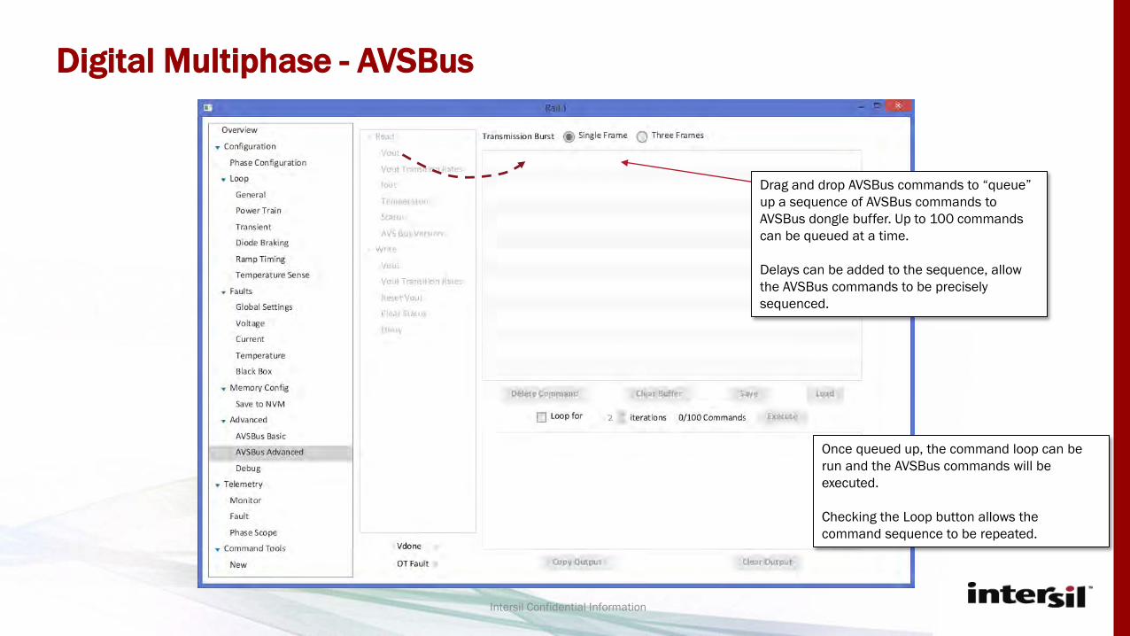
Digital Multiphase - AVSBus
Intersil Confidential Information
Drag and drop AVSBus commands to “queue” up a sequence of AVSBus commands to AVSBus dongle buffer. Up to 100 commands can be queued at a time.
Delays can be added to the sequence, allow the AVSBus commands to be precisely sequenced.
Once queued up, the command loop can be run and the AVSBus commands will be executed.
Checking the Loop button allows the command sequence to be repeated.

AVSBus – Example Vout Set point Change
45
0.7V
1.0V
CH2: AVSCLKCH3: AVSDATA
<20us
1.0V
0.7V<20us
AVS_CLK = 25MHzSlew = 25mV/us
Using the AVSBus interface, 300mV change in Vout takes <20us, enabling rapid changes in CPU power states
CH1: Vout CH1: Vout
CH2: AVSCLKCH3: AVSDATA
~3us

Saving Settings to NVM
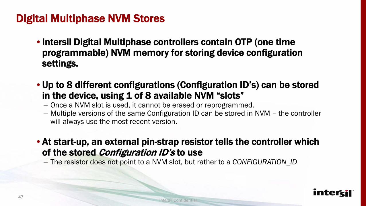
• Intersil Digital Multiphase controllers contain OTP (one time programmable) NVM memory for storing device configuration settings.
• Up to 8 different configurations (Configuration ID’s) can be stored in the device, using 1 of 8 available NVM “slots”– Once a NVM slot is used, it cannot be erased or reprogrammed.– Multiple versions of the same Configuration ID can be stored in NVM – the controller
will always use the most recent version.
• At start-up, an external pin-strap resistor tells the controller which of the stored Configuration ID’s to use– The resistor does not point to a NVM slot, but rather to a CONFIGURATION_ID
Digital Multiphase NVM Stores
47Intersil Confidential

Example Configuration Stores
48
Cfg 1 (Rev 0)
Cfg 1 (Rev 1)
Cfg 4 (Rev 0)
Slot 8 - Blank
Slot 4 - Blank
Slot 5 - Blank
Slot 6 - Blank
Slot 7 - Blank
Example: Storing ConfigsMemory Allocation
• A 4+0 design configuration is first stored as Config ID 1
• The 4+0 design is then updated due to design change (ex. Vboot change), resulting in a new Config ID 1 store.
• A 3+1 design configuration is stored as Config ID 4
Upon Power Up
• A 1800 Ohm Rconfig will result in Cfg1 (Rev 1) to be used. Only the latest revision will ever be loaded
• A 3300 Ohm Rconfig will result in Cfg4 (Rev0) to be used
Intersil Confidential
In this example:- 2 CONFIG IDs are stored in OTP- 3 OTP slots are used, however. CFG1 (Rev
0) uses a slot, but is not accessible since it has been replaced by CFG1 (Rev 1)

Saving Settings to NVM
49
To save the current config to the on-board memory in the device that is connected.
First click on the “Save to NVM” in the Rail Inspector
If the project has not been saved since the most recent changes, the “Save Project” button will be enabled and the “Save” buttons for the configuration IDs will be disabled.

Saving Settings to NVM
50
After project has been saved, “Save Project” will gray out, indicating the latest settings have been saved.
“Save” options will now be active, allowing the project to be saved to 1 of 8 available CFG ID’s

Saving Settings to NVM
51
Once the configuration has been saved, input power to the
part should be cycled.
Re-loading the NVM screen will show that there are now 7
saves remaining. In addition, the NVM contents will show a match to the project in your
directory.
Clicking on the “Match Found” button will show information for
the matching project.

Hex File Export

• To support production programming, Digital Multiphase controllers support a HEX export utility.– Once a design has been finalized, the exported HEX file is used to program devices on
high speed production programmers.
• The HEX export utility is available under the “Utilities” menu on the main PowerNavigator screen.
• Using this utility, multiple projects can be combined into a single HEX file– Each project is assigned one of 8 available CONFIG_IDs– An external resistor is then used to select the proper CONFIG_ID
Digital Multiphase Hex File Export
53Intersil Confidential

Digital Multiphase – Saving a Project
Intersil Confidential Information
Select “Save” from File Menu. Be sure to save revision information in project name

Digital Multiphase – Exporting HEX File
Intersil Confidential Information
After saving, select “Multiphase Hex Exporter” from Utilities Menu.
Digital Multiphase – Exporting HEX File
Intersil Confidential Information
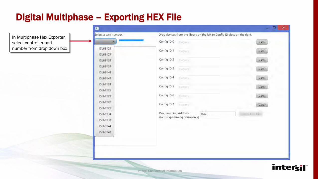
In Multiphase Hex Exporter, select controller part number from drop down box

Digital Multiphase – Exporting HEX File
Intersil Confidential Information
After part number is selected, the Hex Exporter tool will scan the PowerNavigator Projects folder for all project IDs with that part number.
After scanning is complete, all projects using that part number will be displayed
Select project, then Click and drag project into desired Config ID.
Set programming address to match address of controller in programming environment.

Digital Multiphase – Exporting HEX File
Intersil Confidential Information
After all projects have been loaded, click “Export Hex File”
In resulting pop-up window, select save location and file name for Hex file. To ease Hex file management, be sure to include version numbering in Hex file.
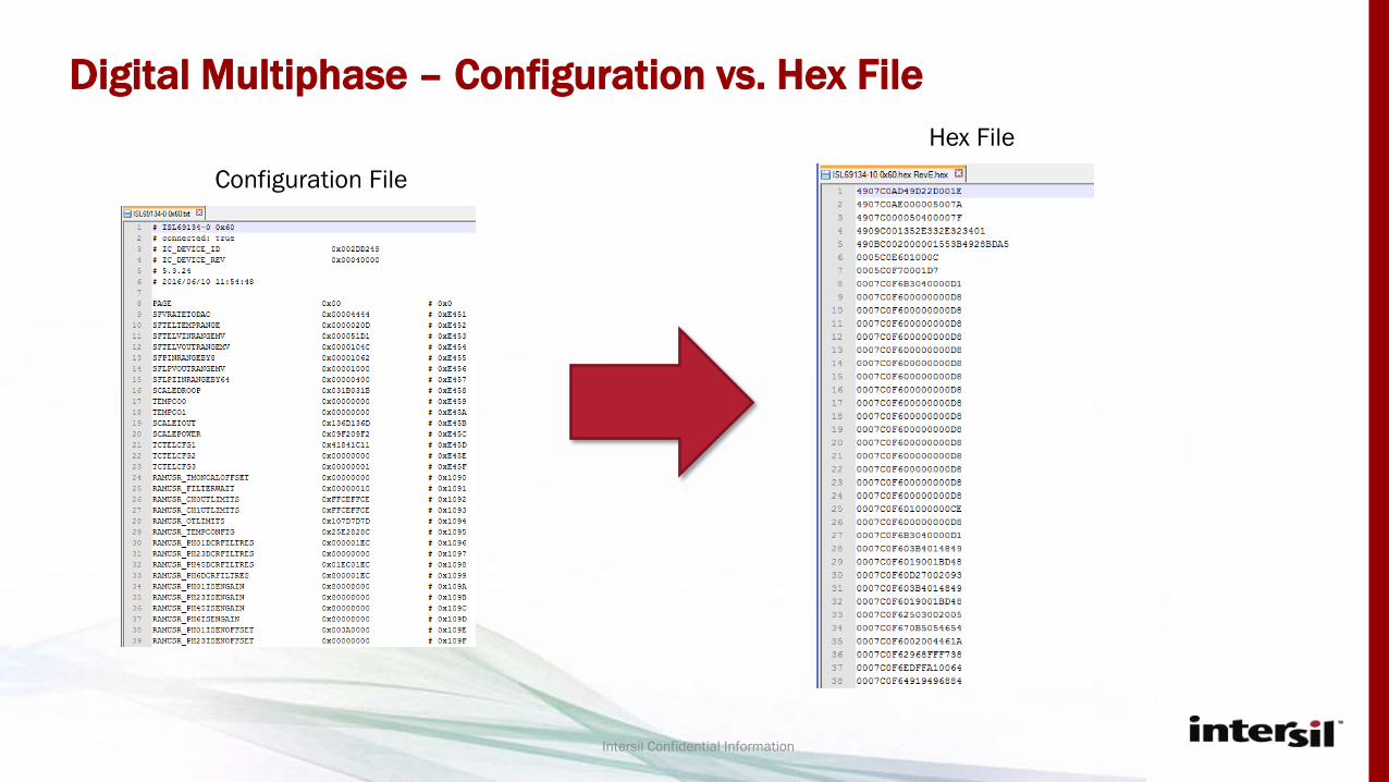
Digital Multiphase – Configuration vs. Hex File
Intersil Confidential Information
Configuration File
Hex File

Project Compare

Digital Multiphase – Project Compare
Intersil Confidential Information
Select “Project Comparison” from Utilities menu

Digital Multiphase – Connecting to Hardware
Intersil Confidential Information
Click “Load Project”
In resulting pop-up window, navigate to project you wish to compare.

Digital Multiphase – Connecting to Hardware
Intersil Confidential Information
After projects have been loaded, expand to show individual rails
Drag and drop rails into compare window

Digital Multiphase – Connecting to Hardware
Intersil Confidential Information
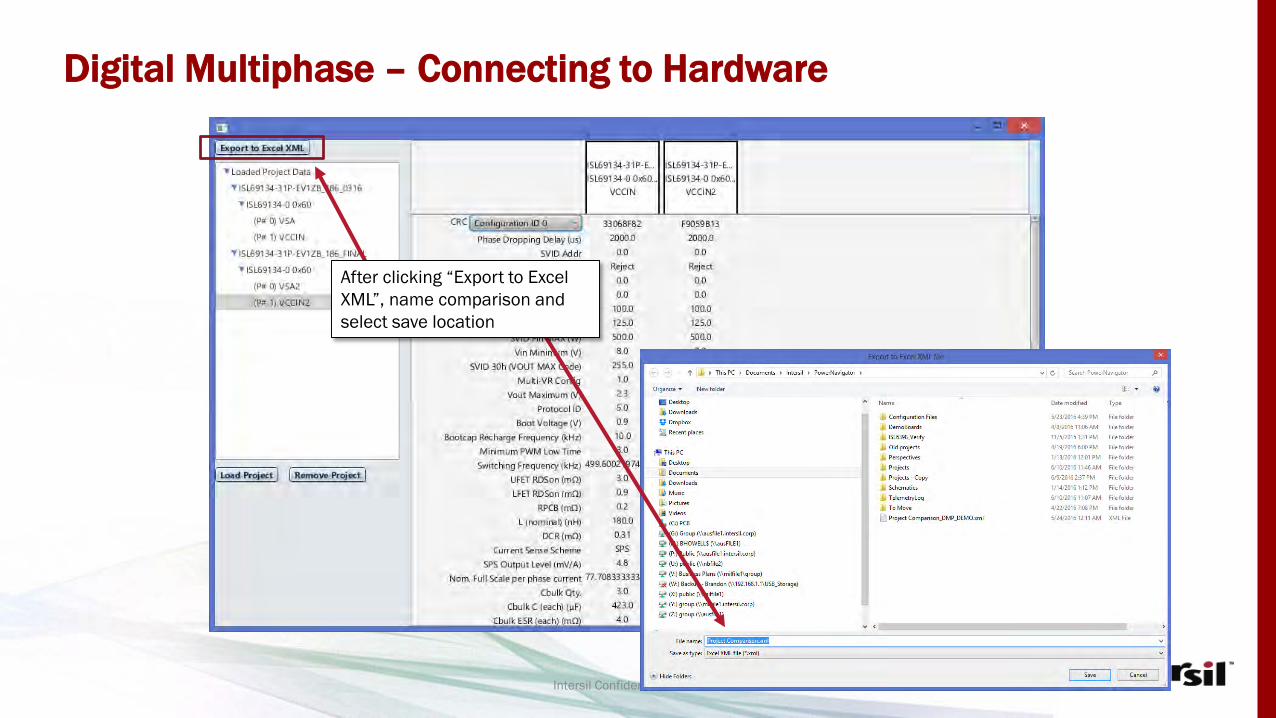
Scan List for differences, OR click “Export to Excel XML”
Digital Multiphase – Connecting to Hardware
Intersil Confidential Information
After clicking “Export to Excel XML”, name comparison and select save location

Digital Multiphase – Connecting to Hardware
Intersil Confidential Information
Compare differences will be automatically highlighted in RED

www.intersil.com