Powerdrive MD2S - Leroy-Somer · 4 Powerdrive MD2S Installation guide 4972 en - 2017.08 / d...
52
Powerdrive MD2S Installation guide 100T to 1700T 270TH to 1500TH High-power free-standing drive solution Part number: 4972 en 2017.08 / d
Transcript of Powerdrive MD2S - Leroy-Somer · 4 Powerdrive MD2S Installation guide 4972 en - 2017.08 / d...

Powerdrive MD2S
Installation guide
100T to 1700T270TH to 1500THHigh-power free-standing drive solution
Part number: 4972 en 2017.08 / d
2
Powerdrive MD2S Installation guide4972 en - 2017.08 / d
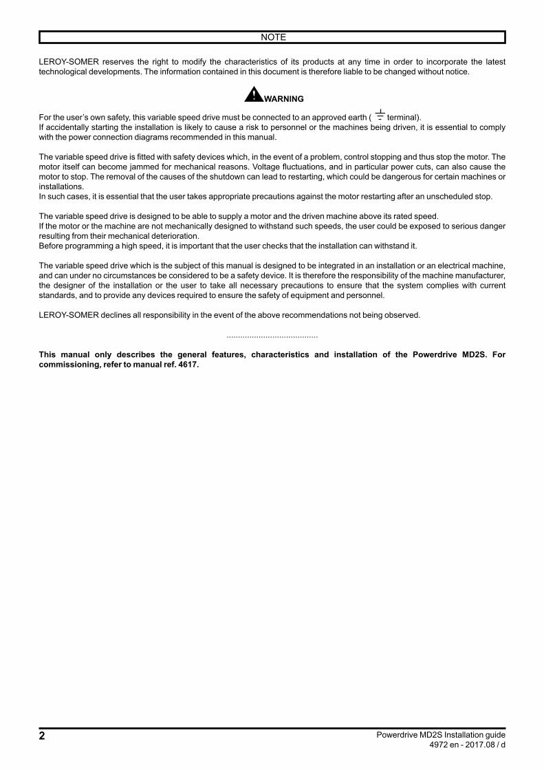
LEROY-SOMER reserves the right to modify the characteristics of its products at any time in order to incorporate the latest technological developments. The information contained in this document is therefore liable to be changed without notice.
WARNING
For the user’s own safety, this variable speed drive must be connected to an approved earth ( terminal).If accidentally starting the installation is likely to cause a risk to personnel or the machines being driven, it is essential to comply with the power connection diagrams recommended in this manual.
The variable speed drive is fitted with safety devices which, in the event of a problem, control stopping and thus stop the motor. The motor itself can become jammed for mechanical reasons. Voltage fluctuations, and in particular power cuts, can also cause the motor to stop. The removal of the causes of the shutdown can lead to restarting, which could be dangerous for certain machines or installations.In such cases, it is essential that the user takes appropriate precautions against the motor restarting after an unscheduled stop.
The variable speed drive is designed to be able to supply a motor and the driven machine above its rated speed.If the motor or the machine are not mechanically designed to withstand such speeds, the user could be exposed to serious danger resulting from their mechanical deterioration.Before programming a high speed, it is important that the user checks that the installation can withstand it.
The variable speed drive which is the subject of this manual is designed to be integrated in an installation or an electrical machine, and can under no circumstances be considered to be a safety device. It is therefore the responsibility of the machine manufacturer, the designer of the installation or the user to take all necessary precautions to ensure that the system complies with current standards, and to provide any devices required to ensure the safety of equipment and personnel.
LEROY-SOMER declines all responsibility in the event of the above recommendations not being observed.
........................................
This manual only describes the general features, characteristics and installation of the Powerdrive MD2S. For commissioning, refer to manual ref. 4617.
NOTE

3
Powerdrive MD2S Installation guide4972 en - 2017.08 / d
(In accordance with the low voltage directive 2006/95/EC)Throughout the manual, this symbol warns of consequences which can arise from inappropriate use of the drive, since electrical risks can lead to material or physical damage as well as constituting a fire hazard.
1 - General informationDepending on their degree of protection, variable speed drives can contain unprotected live parts, which can be moving or rotating, as well as hot surfaces, during operation.Unjustified removal of protection devices, incorrect use, faulty installation or inappropriate operation could represent a serious risk to personnel and equipment.For further information, consult the manual.All work relating to transportation, installation, commissioning and maintenance must be performed by experienced, qualified personnel (see IEC 364, CENELEC HD 384 or DIN VDE 0100, as well as national specifications for installation and accident prevention).In these basic safety instructions, qualified personnel means persons competent to install, mount, commission and operate the product and possessing the relevant qualifications.
2 - UseVariable speed drives are components designed for integration in installations or electrical machines.When integrated in a machine, commissioning must not take place until it has been verified that the machine conforms with directive 2006/42/EC (Machinery Directive). It is also necessary to comply with standard EN 60204, which stipulates in particular that electrical actuators (which include variable speed drives) cannot be considered as circuit-breaking devices and certainly not as isolating switches.Commissioning can take place only if the requirements of the Electromagnetic Compatibility Directive (EMC 2004/108/EC) are met.The variable speed drives meet the requirements of the Low Voltage Directive 2006/95/EC. The harmonized standards of the DIN VDE 0160 series in connection with standard VDE 0660, part 500 and EN 60146/VDE 0558 are also applicable.The technical characteristics and instructions concerning the connection conditions specified on the nameplate and in the documentation provided must be observed without fail.
3 - Transportation, storageAll instructions concerning transportation, storage and correct handling must be observed.The climatic conditions specified in the technical manual must be observed.
4 - InstallationThe installation and cooling of equipment must comply with the specifications in the manual supplied with the product.Variable speed drives must be protected against any excessive stress. In particular, there must be no damage to parts and/or modification of the clearance between components during transportation and handling. Avoid touching the electronic components and contact parts.Variable speed drives contain parts that are sensitive to electrostatic stresses and can easily be damaged if handled incorrectly. Electrical components must not be exposed to mechanical damage or destruction (risks to health!).
5 - Electrical connectionWhen work is performed on variable speed drives that are powered up, the national accident prevention regulations must be respected.The electrical installation must comply with the relevant specifications (for example conductor cross-sections, protection via fused circuit-breaker, connection of protective conductor). More detailed information is given in the manual.Instructions for an installation which meets the requirements for electromagnetic compatibility, such as screening, earthing, presence of filters and correct laying of cables and conductors, are given in the documentation supplied with the variable speed drives. These instructions must be followed in all cases, even if the variable speed drive carries the CE mark. Adherence to the limits given in the EMC legislation is the responsibility of the manufacturer of the installation or the machine.
6 - OperationInstallations in which variable speed drives are to be integrated must be fitted with additional protection and monitoring devices as laid down in the current relevant safety regulations, such as the law on technical equipment, accident prevention regulations, etc. Modifications to the variable speed drives using control software are permitted.Active parts of the device and the live power connections must not be touched immediately after the variable speed drive is powered down, as the capacitors could still be charged. In view of this, the warnings fixed to the variable speed drives must be observed.Permanent magnet motors generate electrical energy while they are rotating, even when the drive is switched off. In this case, the drive continues to be powered by the motor terminals. If the load is capable of turning the motor, a switching device must be provided upstream of the motor to isolate the drive during maintenance operations.During operation, all doors and protective covers must be kept closed.
7 - Servicing and maintenanceRefer to the manufacturer’s documentation.See the Maintenance section in this document.
This manual is to be given to the end user.
SAFETY AND OPERATING INSTRUCTIONS FOR VARIABLE SPEED DRIVES

4
Powerdrive MD2S Installation guide4972 en - 2017.08 / d
MDX-SOFTParameter-setting
software+ PC link cable
MDX-Powerscreen parameter-setting
interface
Compabloc• Axial output
- Helical gears
Orthobloc• Orthogonal output- Helical bevel gears
Radial forced
ventilation
IMfinity® motorLSES-FLSES
LSMV motor
Dyneo® motorLSRPM-PLSRPM
Brake
Axial forced ventilation
Encoder/Sensor
MotorsGearboxes Motor options
Options
Parameter setting Standard
FOREWORD
This manual describes the installation of Powerdrive MD2S variable speed drives. It also gives details of all its options and extensions which the user may choose to suit his requirements.
Powerdrive MD2SCONTENTS
• High-speed fuses• Line choke
• Isolating switch• RFI filter• Encoder or resolver input• Additional I/O• Datalogger• Communication options • IP54 protection• 100 or 200 mm baseplates

5
Powerdrive MD2S Installation guide4972 en - 2017.08 / d
1 - GENERAL INFORMATION .................................................................................................................................. 71.1 - General ........................................................................................................................................................ 71.2 - Product designation .................................................................................................................................... 71.3 - Environmental characteristics ...................................................................................................................... 71.4 - Electrical characteristics .............................................................................................................................. 8
1.4.1 - General characteristics.......................................................................................................................................... 81.4.2 - Electrical characteristics ........................................................................................................................................ 81.4.3 - Derating at low frequency ...................................................................................................................................... 91.4.4 - Derating according to the temperature and switching frequency ......................................................................... 10
2 - MECHANICAL INSTALLATION ......................................................................................................................... 122.1 - Checks upon receipt .................................................................................................................................. 122.2 - Handling .................................................................................................................................................... 122.3 - Installation recommendations ................................................................................................................... 132.4 - Removing and re-fitting the IP21 roof ......................................................................................................... 132.5 - Assembly and dismantling of the IP54 roof ................................................................................................ 132.6 - Dimensions ................................................................................................................................................ 142.7 - Weight ....................................................................................................................................................... 152.8 - Drive losses ............................................................................................................................................... 152.9 - Drive ventilation flow rates and noise levels ............................................................................................... 15
3 - CONNECTIONS ................................................................................................................................................. 163.1 - Power connections .................................................................................................................................... 16
3.1.1 - Location of the control terminal block, fuse boards and external power supply .................................................... 163.1.2 - Electronics and forced ventilation power supply .................................................................................................. 173.1.3 - Characteristics of connection terminals ............................................................................................................... 173.1.4 - Location of power terminal blocks........................................................................................................................ 183.1.5 - Cables and fuses ................................................................................................................................................. 20
3.2 - Connection of the control ........................................................................................................................... 223.2.1 - Control terminal block location............................................................................................................................. 223.2.2 - Control terminal block characteristics .................................................................................................................. 223.2.3 - Factory configuration of control terminal blocks ................................................................................................... 24
3.3 - STO-1/STO-2 inputs: Safe Torque Off function .......................................................................................... 253.3.1 - Single channel locking (SIL1 - PLb) ..................................................................................................................... 253.3.2 - Double channel locking (SIL3 - PLe).................................................................................................................... 25
4 - GENERAL EMC - HARMONICS - MAINS INTERFERENCE ............................................................................. 264.1 - Low-frequency harmonics .......................................................................................................................... 264.2 - Radio-frequency interference: Immunity .................................................................................................... 26
4.2.1 - General ............................................................................................................................................................... 264.2.2 - Standards ............................................................................................................................................................ 264.2.3 - Recommendations .............................................................................................................................................. 26
4.3 - Radio-frequency interference: Emission .................................................................................................... 264.3.1 - General ............................................................................................................................................................... 264.3.2 - Standards ............................................................................................................................................................ 26
4.4 - Mains supply .............................................................................................................................................. 264.4.1 - General ............................................................................................................................................................... 264.4.2 - Mains transient overvoltages ............................................................................................................................... 274.4.3 - Unbalanced power supply ................................................................................................................................... 274.4.4 - Ground connections ............................................................................................................................................ 27
4.5 - Basic precautions for installation .............................................................................................................. 284.5.1 - Wiring inside the cabinet...................................................................................................................................... 284.5.2 - Wiring outside the cabinet ................................................................................................................................... 28
4.6 - Electromagnetic compatibility (EMC) ......................................................................................................... 29
CONTENTS
CONTENTS

6
Powerdrive MD2S Installation guide4972 en - 2017.08 / d
5 - PARAMETER-SETTING INTERFACE AND OPTIONS ...................................................................................... 305.1 - Parameter setting ...................................................................................................................................... 30
5.1.1 - MDX-Powerscreen .............................................................................................................................................. 305.1.2 - MDX-KEYPAD ..................................................................................................................................................... 315.1.3 - MDX-SOFT ......................................................................................................................................................... 31
5.2 - Add-on options ........................................................................................................................................... 325.2.1 - Fieldbus modules ................................................................................................................................................ 325.2.2 - Speed feedback option ........................................................................................................................................ 325.2.3 - MDX-I/O TIMER option ........................................................................................................................................ 345.2.4 - Option installation ................................................................................................................................................ 34
5.3 - Electrical protection ................................................................................................................................... 375.3.1 - aR semi-conductor fuses ..................................................................................................................................... 375.3.2 - Load break switch................................................................................................................................................ 375.3.3 - Fuse combination switch ..................................................................................................................................... 375.3.4 - Circuit Breaker..................................................................................................................................................... 375.3.5 - Emergency stop .................................................................................................................................................. 37
5.4 - RFI filter ..................................................................................................................................................... 385.5 - Line reactors .............................................................................................................................................. 38
5.5.1 - POWERDRIVE MD2S 100T to 270T, 1100T to 1400T and 270TH to 1500TH ..................................................... 385.5.2 - POWERDRIVE MD2S 340T to 470T ................................................................................................................... 385.5.3 - POWERDRIVE MD2S 600T and 900T ................................................................................................................ 38
5.6 - Associated braking module and resistors ................................................................................................... 395.6.1 - Braking modules.................................................................................................................................................. 395.6.2 - Braking resistors.................................................................................................................................................. 39
6 - TRIPS - DIAGNOSTICS ..................................................................................................................................... 406.1 - Safety notice .............................................................................................................................................. 406.2 - Alarms ....................................................................................................................................................... 406.3 - Tripping on a safetrip.................................................................................................................................. 40
7 - MAINTENANCE ................................................................................................................................................. 447.1 - Storage ...................................................................................................................................................... 447.2 - Replacing products .................................................................................................................................... 447.3 - List of spare parts ....................................................................................................................................... 46
CONTENTS

7
GENERAL INFORMATION
Powerdrive MD2S Installation guide4972 en - 2017.08 / d
1 - GENERAL INFORMATION1.1 - GeneralThe Powerdrive MD2S is a variable speed drive with very high performance levels that can be used to control:- Induction motors without a speed sensor (open loop mode select ) for applications that do not need rated torque control above 1/10th of the rated speed.- Induction motors or synchronous permanent magnet motors with virtual speed feedback (flux vector mode with software sensor function ) for applications that require rated torque control from 1/20th of the rated speed.Combined with the MDX-ENCODER option, the Powerdrive MD2S is a drive that can also be used to control asynchronous or synchronous magnet machines for applications that require very high dynamic performances, torque control from zero speed or high speed accuracy (closed loop vector mode with speed feedback ).The performance of the Powerdrive MD2S is compatible with use in all 4 quadrants of the torque/speed plane with the braking module option incorporated.
With IP54 protection (optional), installation is possible directly next to the machine in harsh environments.
1.2 - Product designation POWERDRIVE MD2S - 180 T
*
Drive versionMD2S : 6 pulsesMD2T : 12 pulsesMD2E : 18 pulsesMD2W : 24 pulsesMD2R : AFE
Rating in kVA
3-phase power supplyT : 400 V to 480 VTH : 525 V to 690 V
Modular variable speed drive with flux vector control
Cooling: - : Air L : Liquid
(*) See the corresponding installation manual
Depending on the options installed, a suffix (-B or -O) is added to the product commercial designation.
Nameplate
ENTREE - INPUT
Ph V (V) Hz (Hz) I(A) 3 400-480 50/60 295
TYPE :
S/N : 09999999999
MADE IN FRANCE
Powerdrive MD2S 180T
I(A) = maximum input current for 400 V supply, in normal duty
The nameplate can be found inside the drive cabinet door at the top (another copy can be found on the outside of the drive cabinet, at the top on the right-hand side).
1.3 - Environmental characteristicsCharacteristics Level
Protection IP21 (IP54 as an option)
Storage and transport temperature -30°C to +60°C (see section7.1)
Ambient operating temperature (outside the drive cabinet)
-10°C to +40°C, up to +50°C with derating
Classification of environmental conditions
In accordance with IEC 60721-3-3:• Biological classification in accordance with class 3B1• Classification as regards chemically active substances in acc. with class 3C2• Classification as regards mechanically active substances in acc. with class 3S2
Relative humidity In accordance with IEC 60068-2-56 < 90% non condensing
Altitude
≤ 1,000 m without derating> 1,000 m up to 4000 m maximum (as required):• Current derating of 1% per additional 100 m E.g.: for 1,300 m, derate the Ico and Imax currents by 3%• Operating temperature derating of 0.6°C per 100 mE.g.: for 1,300 m, the electrical characteristics are maintained for an ambient temperature of [40°- (3 x 0.6°)] = 38.2°C.
Vibrations
In accordance with IEC 60068-2-6• Exposed product: 2 m/s² (9-200 Hz), 0.6 mm (2-9 Hz)• Packaged product: 10 m/s² (9-200 Hz), 3 mm (2-9 Hz)
Shocks Packaged product: in accordance with standard IEC 60068-2-29
Atmospheric pressure 700 to 1060 hPa
8
GENERAL INFORMATION
Powerdrive MD2S Installation guide4972 en - 2017.08 / d
1.4 - Electrical characteristicsAll work relating to installation, commissioning and maintenance must be carried out by experienced, qualified personnel.
1.4.1 - General characteristicsCharacteristics Level
Power supply voltage 3-phase supply: 400 V -10% to 480 V +10% ("T" ratings) or 525 V -10% to 690 V +5% ("TH" ratings)
Phase voltage imbalance < 2%
Input frequency "T" ratings: 50 or 60 Hz ± 5% "TH" ratings: 50 Hz ± 5%
Maximum number of power-ups per hour (power) 20
Output frequency range 0 to 590 Hz
ROHS conformance Conforming to standard 2002-95-EC
For operation with a neutral IT point connection, follow the instructions given in section4.4.3
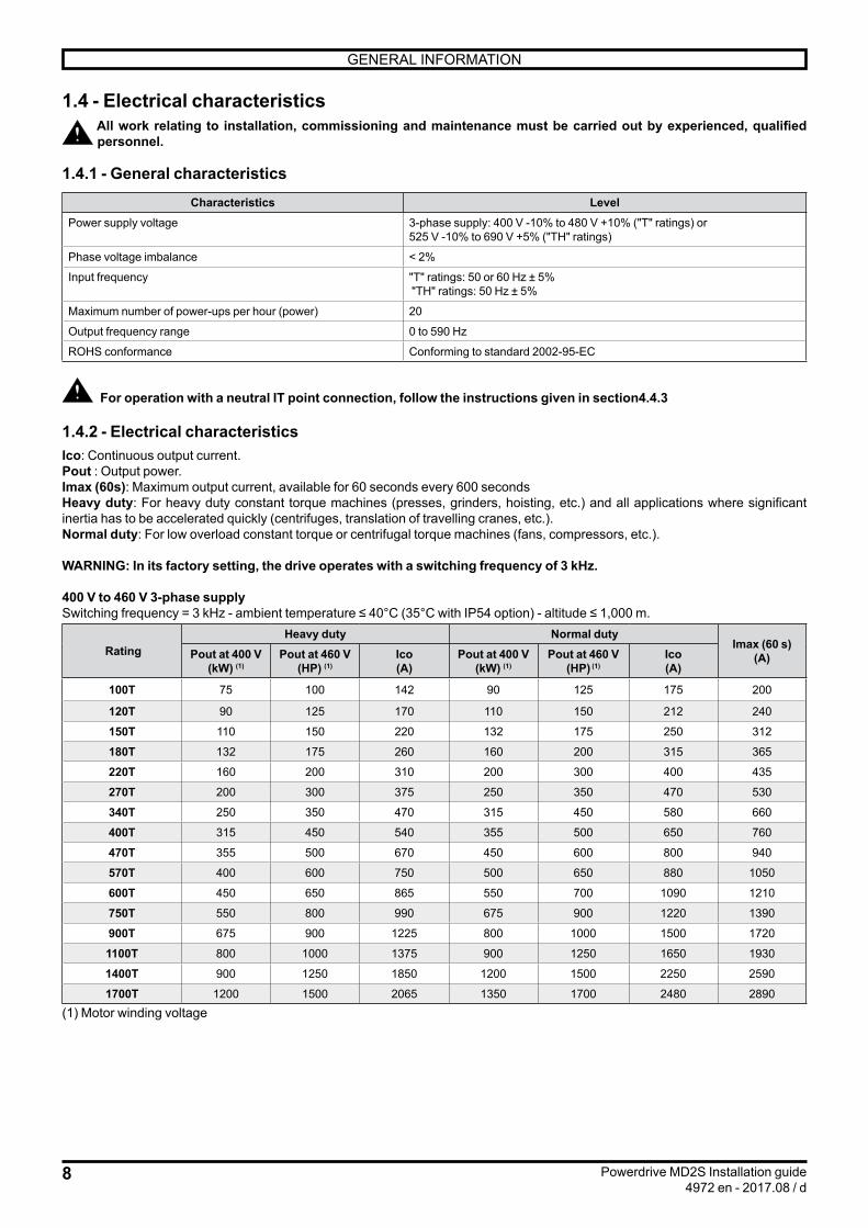
1.4.2 - Electrical characteristicsIco: Continuous output current.Pout : Output power.Imax (60s): Maximum output current, available for 60 seconds every 600 secondsHeavy duty: For heavy duty constant torque machines (presses, grinders, hoisting, etc.) and all applications where significant inertia has to be accelerated quickly (centrifuges, translation of travelling cranes, etc.).Normal duty: For low overload constant torque or centrifugal torque machines (fans, compressors, etc.).
WARNING: In its factory setting, the drive operates with a switching frequency of 3 kHz.
400 V to 460 V 3-phase supplySwitching frequency = 3 kHz - ambient temperature ≤ 40°C (35°C with IP54 option) - altitude ≤ 1,000 m.
RatingHeavy duty Normal duty
Imax (60 s)(A)Pout at 400 V
(kW) (1)Pout at 460 V
(HP) (1)Ico(A)
Pout at 400 V(kW) (1)
Pout at 460 V(HP) (1)
Ico(A)
100T 75 100 142 90 125 175 200
120T 90 125 170 110 150 212 240
150T 110 150 220 132 175 250 312
180T 132 175 260 160 200 315 365
220T 160 200 310 200 300 400 435
270T 200 300 375 250 350 470 530
340T 250 350 470 315 450 580 660
400T 315 450 540 355 500 650 760
470T 355 500 670 450 600 800 940
570T 400 600 750 500 650 880 1050
600T 450 650 865 550 700 1090 1210
750T 550 800 990 675 900 1220 1390
900T 675 900 1225 800 1000 1500 1720
1100T 800 1000 1375 900 1250 1650 1930
1400T 900 1250 1850 1200 1500 2250 2590
1700T 1200 1500 2065 1350 1700 2480 2890(1) Motor winding voltage

9
0 5 10 15 20
20 %
40 %
60 %
80 %
100 %
120 %
140 %
GENERAL INFORMATION
Powerdrive MD2S Installation guide4972 en - 2017.08 / d
Frequency(Hz)
% Ico or% Imax (60 s)
525 V to 690 V 3-phase supply Switching frequency = 3 kHz - ambient temperature ≤ 40°C (35°C with IP54 option) - altitude ≤ 1000 m.
Rating Powerdrive MD2S
Heavy duty Normal dutyImax (60s)
(A)Pout at 575 V(HP) (1)
Pout at 690 V(kW) (1)
Ico(A)
Pout at 575 V(HP) (1)
Pout at 690 V(kW) (1)
Ico(A)
270TH 200 200 220 250 250 280 308
340TH 250 250 270 300 300 340 378
400TH 300 300 335 400 400 415 465
500TH 400 400 390 500 500 470 545
600TH 450 450 490 600 600 630 638
750TH 600 600 615 700 700 780 800
900TH 700 700 720 900 900 880 1000
1200TH 900 900 900 1100 1000 1180 1230
1500TH 1100 1000 1075 1250 1250 1320 1485(1) Motor winding voltage
1.4.3 - Derating at low frequencyMeasuring the temperature of the power bridges in conjunction with thermal modelling of the IGBTs ensures protection against overheating of the Powerdrive MD2S.
At low output (motor) frequencies, IGBT modules are subject to significant temperature cycling, which can reduce their life. To prevent this risk, the curve opposite indicates the derating for output currents Ico and Imax when operating at low motor frequencies in continuous operation.
1.4.4 - Standard equipmentThe Powerdrive MD2S is equipped as standard with a line choke and high-speed fuses.
1.4.5 - Derating according to the temperature and switching frequencySee the derating tables on the next pages.
For intermediate switching frequencies (3.5 - 4.5 - 5.5 kHz), the available current value will be the average of the upper frequency and lower frequency currents.
In the IP54 version, with an ambient temperature of 40°C, the available current value will be the average of the currents at 35°C and 45°C.

10
GENERAL INFORMATION
Powerdrive MD2S Installation guide4972 en - 2017.08 / d
Ambient temperature ≤ 40°C (≤ 35°C with IP54 option) - altitude ≤ 1,000 m.
Rating
Ico (A)
Heavy duty Normal duty
2 kHz 3 kHz 4 kHz 5 kHz 6 kHz 2 kHz 3 kHz 4 kHz 5 kHz 6 kHz
400 V supply
100T 142 142 142 130 118 175 175 162 148 134
120T 170 170 165 150 135 220 212 188 170 154
150T 220 220 195 175 160 260 250 224 200 182
180T 260 260 260 260 250 315 315 310 305 285
220T 310 310 310 310 285 400 400 385 355 325
270T 375 375 375 350 320 470 470 440 400 365
340T 470 470 460 415 380 580 580 525 475 430
400T 540 540 530 480 430 650 650 605 545 490
470T 670 670 640 570 515 800 800 725 650 585
570T 750 750 660 - - 915 880 750 - -
600T 865 865 860 785 705 1090 1090 980 890 800
750T 990 990 990 900 810 1220 1220 1130 1020 920
900T 1225 1225 1195 1075 960 1500 1500 1360 1220 1090
1100T 1375 1375 1240 - - 1720 1650 1410 - -
1400T 1850 1850 1795 - - 2250 2250 2040 - -
1700T 2065 2065 1860 - - 2580 2480 2110 - -
460/480 V supply
100T 142 142 136 122 112 175 172 154 138 126
120T 170 170 155 140 125 215 200 176 158 144
150T 220 210 185 160 145 255 238 210 186 168
180T 260 260 260 260 230 315 310 305 295 265
220T 310 310 310 295 265 400 395 370 335 300
270T 375 375 370 330 295 470 465 420 375 335
340T 470 470 425 380 340 580 560 485 430 385
400T 540 535 490 430 380 650 610 555 490 435
470T 670 660 585 515 460 800 750 665 585 525
570T 750 715 630 - - 890 815 715 - -
600T 865 865 800 705 635 1090 1050 910 800 720
750T 990 990 915 810 715 1220 1140 1040 920 810
900T 1225 1225 1100 960 860 1500 1410 1250 1090 980
1100T 1375 1345 1180 - - 1670 1530 1340 - -
1400T 1850 1850 1645 - - 2250 2110 1870 - -
1700T 2065 2015 1770 - - 2500 2290 2010 - -
525/690 V supply
270TH 220 220 220 - - 280 280 250 - -
340TH 270 270 270 - - 340 340 310 - -
400TH 335 335 290 - - 415 415 330 - -
500TH 390 390 305 - - 500 470 350 - -
600TH 490 490 490 - - 630 630 580 - -
750TH 615 615 545 - - 780 780 620 - -
900TH 720 720 570 - - 940 880 650 - -
1200TH 900 900 825 - - 1180 1180 940 - -
1500TH 1075 1075 860 - - 1410 1320 980 - -

11
GENERAL INFORMATION
Powerdrive MD2S Installation guide4972 en - 2017.08 / d
Ambient temperature ≤ 50°C (≤ 45°C with IP54 option) - altitude ≤ 1,000 m.
Rating
Ico (A)
Heavy duty Normal duty
2 kHz 3 kHz 4 kHz 5 kHz 6 kHz 2 kHz 3 kHz 4 kHz 5 kHz 6 kHz
400 V supply
100T 140 140 130 120 110 175 168 150 136 124
120T 170 170 150 135 125 215 192 172 156 142
150T 220 205 180 160 145 255 232 206 184 166
180T 260 260 260 255 230 315 315 305 290 260
220T 310 310 310 285 260 400 390 360 325 295
270T 375 375 360 320 290 470 450 410 365 330
340T 470 470 415 375 340 570 540 475 425 385
400T 540 520 485 425 380 630 590 550 485 435
470T 670 650 575 515 460 780 740 655 585 525
570T 750 685 630 - - 890 780 715 - -
600T 865 865 785 695 635 1070 1010 890 790 720
750T 990 970 905 800 715 1180 1100 1030 910 810
900T 1225 1225 1085 960 860 1460 1390 1230 1090 980
1100T 1375 1285 1180 - - 1670 1460 1340 - -
1400T 1850 1830 1620 - - 2190 2080 1840 - -
1700T 2065 1930 1770 - - 2500 2190 2010 - -
460/480 V supply
100T 140 140 125 110 100 175 160 142 126 114
120T 170 160 140 125 115 210 184 162 146 130
150T 220 190 170 150 135 254 220 192 172 154
180T 260 260 260 235 215 315 305 295 270 245
220T 310 310 300 265 235 400 385 340 305 270
270T 375 375 340 300 265 470 435 385 340 305
340T 470 450 380 340 305 570 510 435 385 345
400T 540 485 440 380 340 630 550 500 435 385
470T 670 600 525 460 410 780 685 595 525 465
570T 740 650 570 - - 840 740 650 - -
600T 865 835 715 635 565 1070 950 810 720 640
750T 990 905 825 715 635 1180 1030 940 810 720
900T 1225 1125 975 860 765 1460 1280 1110 980 870
1100T 1375 1225 1075 - - 1570 1390 1220 - -
1400T 1850 1700 1470 - - 2190 1930 1670 - -
1700T 2065 1830 1610 - - 2360 2080 1830 - -
525/690 V supply
270TH 220 210 190 - - 280 240 220 - -
340TH 270 270 235 - - 340 310 270 - -
400TH 335 335 300 - - 415 400 340 - -
500TH 390 365 290 - - 500 415 330 - -
600TH 490 490 440 - - 630 580 500 - -
750TH 615 615 555 - - 780 750 630 - -
900TH 720 685 545 - - 940 780 620 - -
1200TH 900 900 835 - - 1170 1120 950 - -
1500TH 1075 1030 820 - - 1410 1170 930 - -

12
60° mini
60° mini
60° mini
60° mini
L
L
L
L
MECHANICAL INSTALLATION
Powerdrive MD2S Installation guide4972 en - 2017.08 / d
L= 4x 400 mmor 4x 600 mm
L= 3x 400 mmor 3x 600 mm
L = 2x 400 mmor 2x 600 mmor 2x 600 + 400 mm
L = 400 mmor 600 mmor 600 + 400 mm
2 - MECHANICAL INSTALLATION• It is the responsibility of the owner or user of the Powerdrive MD2S to ensure that installation,
operation and maintenance of the drive and its options comply with legislation relating to the safety of equipment and personnel, and with the current regulations in the country of use.• The Powerdrive MD2S drives must be installed in an environment free from conducting dust, corrosive fumes, gases and fluids, and condensation (class 2 according to IEC 664-1). The Powerdrive MD2S must not be installed near flammable materials. The drives must not be installed in hazardous areas unless they are in appropriate enclosures. In this case, the installation must be approved.• In atmospheres where condensation can form, install a heating system (to be switched off when the drive is operating). • Prevent access by unauthorized personnel.
2.1 - Checks on receipt
Make sure that the drive cabinet has been transported vertically, otherwise it could be
damaged.
Before installing the Powerdrive MD2S, check that:- The drive has not been damaged during transport- The information on the nameplate is compatible with the power supply
2.2 - Handling• The center of gravity could be high up and/or off-centre, so beware of the risk of the drive cabinet tipping over.
• Check that the handling equipment is suitable for the weight to be handled.• The lifting accessories provided are limited solely to handling the drive cabinet. If subsequent handling operations are carried out, always check that these lifting accessories are in good condition.
The drive cabinet must be handled without the IP21 or IP54 roof in place.The Powerdrive MD2S IP21 versions are supplied with the roof assembled. Before handling the drive cabinet, follow the procedure described in section2.4. For handling, follow the instructions below, and then re-fit the roof.The Powerdrive MD2S IP54 versions are supplied with the lifting rings or rails fitted. When handling the drive cabinet, follow the instructions below, depending on the cubicle width, as indicated below. After handling, assemble the roof as described in section 2.5.
Above 2,400 mm wide (W), a baseplate 100 mm high is installed as standard to ensure the rigidity of all the drive cabinets.

13
MECHANICAL INSTALLATION
Powerdrive MD2S Installation guide4972 en - 2017.08 / d
2.5 - Assembly and removal of the IP54 roof• Assembly:1 - Remove the 4 lifting rings or the 2 lifting rails.2 - Open up the roof assembly as shown in the diagrams below. The side panels with no vent should be mounted facing one another; the rear of the drive will have no vent.3 - Insert the specially supplied M12 screws through the roof assembly and tighten.4 - Adjust the roof assembly to optimize sealing. 5 - Finally tighten the fixing screws (tightening torque: 20 N.m).
• Removal, if necessary:Reverse the procedure.
2.3 - Installation recommendationsEnsure that hot air is not being recycled via the air inlets by leaving sufficient free space above the Powerdrive MD2S or providing a means of evacuating the hot air expelled by the product. If necessary, add a suction hood. Never obstruct the drive ventilation grilles; the air intake filters must be cleaned and changed regularly.
After connecting the power, reposition the cable bush plates at the back of the drive cabinet and fill
any gaps with expanding foam.
2.4 - Removing and re-fitting the IP21 roof• Removal1 – Take out the M12 screws.2 – Take off the roof(s).3 - Screw in the 4 lifting rings or the 2 lifting rails with the M12 screws at the places indicated (tightening torque = 20 N.m).
• Re-fittingReverse the procedure.

14
MECHANICAL INSTALLATION
Powerdrive MD2S Installation guide4972 en - 2017.08 / d
2.6 - DimensionsThe cabinet-mounted Powerdrive MD2S solution is obtained by assembling drive cabinet modules 400 or 600 mm wide and 600 mm deep. The table below gives the product width (W in mm) depending on the options incorporated:
No options (-B) With options (-O)
MD2S ratings WidthW (mm) Switch RFI filter Braking
transistor (1)Width
W (mm)
100T to 150T 406 406
180T to 270T 406 606
340T & 400T 606 1006
470T & 570T 606 1006
600T to 1100T 1206 1806
1400T & 1700T 1806 - 2406 (2)
270TH to 500TH 606 1006
600TH to 900TH 1206 1606
1200TH to 1500TH 1806 - 2806 (2)
(1) The braking transistor kit comprises an MD2TF and a thermal relay calibrated to the braking resistor.
The following options can be incorporated into the Powerdrive MD2S without altering its size:• MD-AU1 emergency stop• Communication modules• Additional I/O modules• Speed feedback modules
H
WD = 600 mm
The table below gives the product height (H) depending on the options incorporated:
Option Height (mm)Powerdrive MD2S (standard) 2100
IP21 protection + 0
IP54 protection + 100
100 mm baseplate + 100
200 mm baseplate + 200
Baseplate for width ≥ 2,400 mm (2) + 100
(2) Above 2,400 mm long (L), a baseplate 100 mm high must always be installed to ensure the rigidity of all the drive cabinets. This baseplate does not allow the cables to pass through, but can be combined with a 100 or 200 mm baseplate.
For more precise information depending on the options, use the LEROY-SOMER configurator:• http://configurateurls.leroy-somer.com

15
MECHANICAL INSTALLATION
Powerdrive MD2S Installation guide4972 en - 2017.08 / d
2.7 - WeightThe values indicated in the table below are maximum net weights.
Powerdrive MD2S rating
Weightw/o option (kg)
Maximum weight (kg)
100T to 150T 225 260
180T to 270T 260 360
340T & 400T 380 560
470T & 570T 410 610
600T & 750T 760 1100
900T & 1100T 820 1220
1400T & 1700T 1350 1720
270TH & 340TH 355 560
400TH & 500TH 400 620
600TH 720 780
750TH & 900TH 810 1050
1200TH & 1500TH 1250 1520
2.8 - Drive lossesLosses according to the switching frequency for currents at 40°C and normal duty.
MD2S rating
Losses (kW)
2 kHz 3 kHz 4 kHz 5 kHz 6 kHz
100T 2.3 2.4 2.4 2.3 2.2
120T 2.9 2.9 2.8 2.7 2.6
150T 3.4 3.5 3.3 3.1 3.1
180T 4.1 4.4 4.6 4.8 4.8
220T 5.3 5.5 5.7 5.6 5.4
270T 6.2 6.5 6.5 6.3 6.1
340T 7.6 8.0 7.7 7.4 7.2
400T 8.6 9.0 8.9 8.5 8.2
470T 10.5 11.1 10.6 10.2 9.8
570T 12.0 12.2 11.0 - -
600T 14.3 15.1 14.4 13.9 13.4
750T 16.1 16.9 16.6 16.0 15.4
900T 19.7 20.8 20.0 19.1 18.3
1100T 22.6 22.9 20.7 - -
1400T 29.6 31.2 30.0 - -
1700T 34.0 34.4 31.0 - -
270TH 6.4 6.7 6.6 - -
340TH 7.7 8.1 8.2 - -
400TH 9.4 9.9 8.8 - -
500TH 11.4 11.2 9.3 - -
600TH 14.3 15.1 15.4 - -
750TH 17.7 18.6 16.4 - -
900TH 21.3 21.0 17.2 - -
1200TH 26.8 28.2 24.9 - -
1500TH 32.0 31.6 26.0 - -
Note: The values given above correspond to operation in normal duty and the choke losses are included.
2.9 - Drive ventilation flow rates and noise levels
Powerdrive MD2S rating
Forced ventilation flow rates
(m3/h)
Noise level(dBA)
100T to 150T 600 75
180T to 270T 1200 79
340T to 570T 1700 77
600T to 1100T 3400 80
1400T & 1700T 5100 82
270TH to 500TH 1700 77
600TH to 900TH 3400 80
1200TH and 1500TH 5100 82
Air can exit on all sides of the roof. The drive cabinet can be installed with one side only against a wall (with the IP21 or IP54 roofs). Under no circumstance must the difference between the drive cabinet internal temperature and the ambient temperature outside the cabinet exceed 5°C.
In atmospheres where condensation can form, install a heating system (to be switched off when the drive is operating). It is advisable to control the heating system automatically.
Air outlets
Air inlets

16
CONNECTIONS
Powerdrive MD2S Installation guide4972 en - 2017.08 / d
3.1.2 - Connection terminal characteristics
Functions/connections Marking
Type of connection and tightening torque
100T to 150T 180T to 270T 340T to 1400T270TH to 1500TH
AC power supply L1, L2, L3,or R, S, T M10 screw bolt - 20 Nm
Motor outputs U , V, W
Earth PE M10 bolt - 20 Nm
Braking resistor (1) BR1, BR2 M8 bolt - 12 Nm
Do not exceed the indicated maximum tightening torque.
(1) If the braking transistor option is installed.
3 - CONNECTIONS
• All connection work must be performed by qualified electricians in accordance with the laws in force in the country where the drive is installed. This includes grounding to ensure that no directly accessible part of the drive can be at the AC supply voltage or any other voltage which may be dangerous. • The drive must be supplied via an approved circuit-breaking device so that it can be powered down safely. • The optional switch supplied with the drive does not isolate the drive input busbars. It must without fail be associated with a circuit-breaking device in the switchboard.• The drive power supply must be protected against overloads and short-circuits.• Check that the voltage and current of the drive, the motor and the AC supply are compatible.• The voltages on the connections of the AC supply, the motor, the braking resistor or the filter can cause fatal electric shocks. The protective plates supplied with the drive must always be installed correctly to protect the user against direct electric shocks.• Only one permanent magnet motor can be connected to the drive output. It is advisable to install a circuit-breaking device between the permanent magnet motor and the drive output to eliminate the risk of hazardous voltage feedback when performing maintenance work.• Also comply with the recommendations in section 7.
3.1 - Power connections
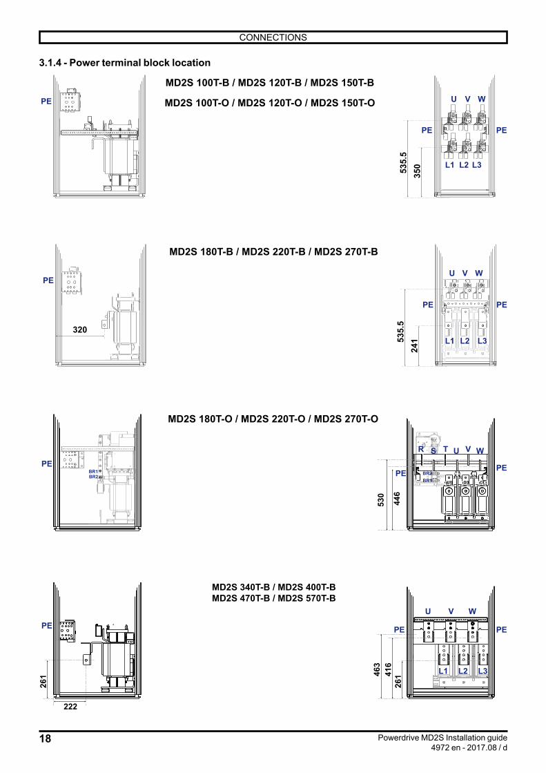
3.1.1 - GeneralThe power connections for the Powerdrive MD2S are detailed for each model in section 3.1.4.
The Powerdrive MD2S versions with ratings higher than 570T are obtained by connecting in parallel Powerdrive MD2S versions with lower ratings.• In the -B version (without options), each drive cabinet has its own U/V/W motor outputs and its own L1/L2/L3 line inputs.• In -O versions (with options) each drive cabinet has its own U/V/W motor outputs; the R/S/T line inputs are contained in the option cabinet.
• The cables for each of the motor U/V/W phases must be distributed evenly over the U/V/W connection plates in each drive cabinet.
• In -B versions, the incoming line cables must be distributed evenly over the L1/L2/L3 connection plates in each drive cabinet.

17
CONNECTIONS
Powerdrive MD2S Installation guide4972 en - 2017.08 / d
3.1.3.2 - Fuse boards
Depending on the rating, the Powerdrive MD2S can contain one or more identical fuse boards: - 100T to 270T: 1 board (1) - 340T to 570T & 270TH to 500TH: 1 board (2) - 600T to 1100T & 600TH to 900TH: 2 boards (2) - 1400T & 1200TH and 1500TH & 1700TH: 3 boards (2)(1) Located on the right-hand side of each cabinet(2) Located on the left-hand side of each cabinet
F1F2 F3 F4 F5 F6
F9F7
PX4
460V(T)
600V(TH)
480V(T)
690V(TH)
400V(T)
500V(TH)
P1
F8
400V(T) / 500V(TH)
460V(T) / 600V(TH)
480V (T) / 690V (TH)
P2P3 P4
P6P7 P8
VF1 VF2 VF3 VF4 VF5
Alim.carte
interfaceEntrée
Alim. S1
EntréeAlim. S2Entrée
alimentationextérieure
ControleVF
Position the F8 fuse according to the versions supply voltage.
Fuse board on control terminal board
3.1.3 - Electronics and forced ventilation power supply
The control electronics and forced ventilation units are supplied through a single-phase transformer whose primary is connected to terminals L1-L2 of the power supply. If necessary, this transformer can be supplied by an external power source (PX4 terminal block).
The neutral of the electronics power supply must not be connected to earth
3.1.3.1 - Electrical characteristics:Ratings Voltage
PrimaryT 400 V±10%/50 Hz or
460-480 V ±10%/60 Hz
TH 500-690 V±5%/50 Hz
Voltage Maximum powerSecondary 1
(Electronics power supply)
230 V isolated 100 VA
Secondary 2(Forced
ventilation and auxiliaries power
supply)
230 V connected
to earth
100T to 150T: 300 VA180T to 270T: 500 VA340T to 570T: 1,200 VA600T to 1100T: 2 x 1,200 VA1400T to 1700T: 3 x 1,200 VA270TH to 500TH: 1,200 VA600TH to 900TH: 2 x 1,200 VA1200TH to 1500TH: 3 x 1,200 VA
18
350535.
5
PE
PE
U V W
L1 L2 L3
MD2S 100T-B / MD2S 120T-B / MD2S 150T-B
MD2S 100T-O / MD2S 120T-O / MD2S 150T-O
PE
24153
5.5
PE
U V W
L1 L2 L3
MD2S 180T-B / MD2S 220T-B / MD2S 270T-B
PE
PE
320
BR1BR2
530
446
PEBR1BR2
MD2S 180T-O / MD2S 220T-O / MD2S 270T-O
R S T U V W
PE PE
L1 L2 L3
U V W
416
26146
3
PE PEPE
222
261
MD2S 340T-B / MD2S 400T-BMD2S 470T-B / MD2S 570T-B
CONNECTIONS
Powerdrive MD2S Installation guide4972 en - 2017.08 / d
3.1.4 - Power terminal block location

19
R T
463
PEPE
S
MD2S 600T-O / MD2S 750T-O / MD2S 900T-O / MD2S 1100T-O
416
464
U1 V1 W1
PE
U2 V2 W2R ST
BR1BR2
L1-1 L2-1 L3-1
U1 V1 W1
416
26146
3PE PEPE
222
L1-2 L2-2 L3-2
U2 V2 W2
261
MD2S 600T-B / MD2S 750T-B / MD2S 900T-B / MD2S 1100T-B
R ST U V W
26146
4
PEPE
BR1BR246
4
MD2S 340T-O / MD2S 400T-OMD2S 470T-O / MD2S 570T-O
PER S T
BR1BR2
416
26146
3
PEPE
222
261
MD2S 1400T-B / MD2S 1700T-B
L1-1 L2-1 L3-1
U1 V1 W1
PE
L1-2 L2-2 L3-2
U2 V2 W2
L1-3 L2-3 L3-3
U3 V3 W3
CONNECTIONS
Powerdrive MD2S Installation guide4972 en - 2017.08 / d

20
50 75 75 75 75 75 95
PE45
50
100PE22
0
55
93
U V WBR1BR2
50 75 75 75 75 75
L1 L2 L3
MD2S 600TH-B / MD2S 750TH-B / MD2S 900TH-B
MD2S 600TH-O / MD2S 750TH-O / MD2S 900TH-O
50 75 75 75 75 75 95PE
4550
100PE22
0
55
93U V W
BR1BR2
R TS
BR
1/B
R2
50 5075 75 105 75 75
U V WL1 L2 L3
PE
93
50
100PE22
0
MD2S 270TH-B / MD2S 340TH-BMD2S 400TH-B / MD2S 500TH-B
BR
1/B
R2
U V W
PEPE 5075 7550
100
220
93
MD2S 270TH-O / MD2S 340TH-OMD2S 400TH-O / MD2S 500TH-O
PER S T
BR1BR226
1464
CONNECTIONS
Powerdrive MD2S Installation guide4972 en - 2017.08 / d

21
U V W
PE
BR1BR2
PE 55 75 75 50 50 5075 75 120 75 75
55
220 50
100
93
50 5075 75 120 75 75 50 75 75 50
L1 L2 L3
MD2S 1200TH-B / MD2S 1500TH-B
U V W
PE
BR1BR2
PE 55 75 75 50 50 5075 75 120 75 75
55
220 50
100
93 R TS
MD2S 1200TH-O / MD2S 1500TH-O
CONNECTIONS
Powerdrive MD2S Installation guide4972 en - 2017.08 / d
22
CONNECTIONS
Powerdrive MD2S Installation guide4972 en - 2017.08 / d
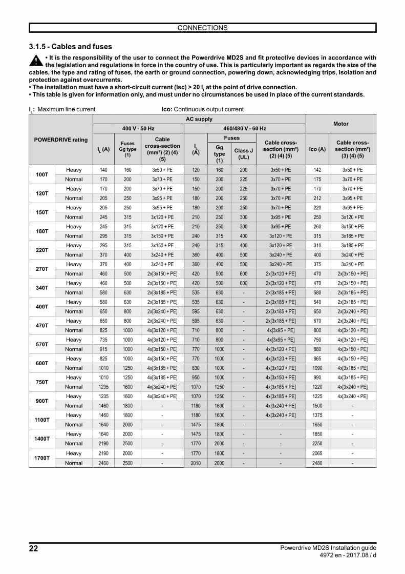
3.1.5 - Cables and fuses• It is the responsibility of the user to connect the Powerdrive MD2S and fit protective devices in accordance with the legislation and regulations in force in the country of use. This is particularly important as regards the size of the
cables, the type and rating of fuses, the earth or ground connection, powering down, acknowledging trips, isolation and protection against overcurrents.• The installation must have a short-circuit current (Isc) > 20 IL at the point of drive connection.• This table is given for information only, and must under no circumstances be used in place of the current standards.
IL: Maximum line current Ico: Continuous output current
POWERDRIVE rating
AC supplyMotor
400 V - 50 Hz 460/480 V - 60 Hz
IL (A)Fuses
Gg type (1)
Cable cross-section (mm²) (2) (4)
(5)
IL (A)
FusesCable cross-section (mm²)
(2) (4) (5)Ico (A)
Cable cross-section (mm²)
(3) (4) (5)Gg
type (1)
Class J (UL)
100THeavy 140 160 3x50 + PE 120 160 200 3x50 + PE 142 3x50 + PENormal 170 200 3x70 + PE 150 200 225 3x70 + PE 175 3x70 + PE
120THeavy 170 200 3x70 + PE 150 200 225 3x70 + PE 170 3x70 + PENormal 205 250 3x95 + PE 180 200 250 3x70 + PE 212 3x95 + PE
150THeavy 205 250 3x95 + PE 180 200 250 3x70 + PE 220 3x95 + PENormal 245 315 3x120 + PE 210 250 300 3x95 + PE 250 3x120 + PE
180THeavy 245 315 3x120 + PE 210 250 300 3x95 + PE 260 3x150 + PENormal 295 315 3x150 + PE 240 315 400 3x120 + PE 315 3x185 + PE
220THeavy 295 315 3x150 + PE 240 315 400 3x120 + PE 310 3x185 + PENormal 370 400 3x240 + PE 360 400 500 3x240 + PE 400 3x240 + PE
270THeavy 370 400 3x240 + PE 360 400 500 3x240 + PE 375 3x240 + PENormal 460 500 2x[3x150 + PE] 420 500 600 2x[3x120 + PE] 470 2x[3x150 + PE]
340THeavy 460 500 2x[3x150 + PE] 420 500 600 2x[3x120 + PE] 470 2x[3x150 + PE]Normal 580 630 2x[3x185 + PE] 535 630 - 2x[3x185 + PE] 580 2x[3x185 + PE]
400THeavy 580 630 2x[3x185 + PE] 535 630 - 2x[3x185 + PE] 540 2x[3x185 + PE]Normal 650 800 2x[3x240 + PE] 595 630 - 2x[3x185 + PE] 650 2x[3x240 + PE]
470THeavy 650 800 2x[3x240 + PE] 595 630 - 2x[3x185 + PE] 670 2x[3x240 + PE]Normal 825 1000 4x[3x120 + PE] 710 800 - 4x[3x95 + PE] 800 4x[3x120 + PE]
570THeavy 735 1000 4x[3x120 + PE] 710 800 - 4x[3x95 + PE] 750 4x[3x120 + PE]Normal 915 1000 4x[3x150 + PE] 770 1000 - 4x[3x120 + PE] 880 4x[3x150 + PE]
600THeavy 825 1000 4x[3x150 + PE] 770 1000 - 4x[3x120 + PE] 865 4x[3x150 + PE]Normal 1010 1250 4x[3x185 + PE] 830 1000 - 4x[3x120 + PE] 1090 4x[3x185 + PE]
750THeavy 1010 1250 4x[3x185 + PE] 950 1000 - 4x[3x150 + PE] 990 4x[3x185 + PE]Normal 1235 1600 4x[3x240 + PE] 1070 1250 - 4x[3x185 + PE] 1220 4x[3x240 + PE]
900THeavy 1235 1600 4x[3x240 + PE] 1070 1250 - 4x[3x185 + PE] 1225 4x[3x240 + PE]Normal 1460 1800 - 1180 1600 - 4x[3x240 + PE] 1500 -
1100THeavy 1460 1800 - 1180 1600 - 4x[3x240 + PE] 1375 -Normal 1640 2000 - 1475 1800 - - 1650 -
1400THeavy 1640 2000 - 1475 1800 - - 1850 -Normal 2190 2500 - 1770 2000 - - 2250 -
1700THeavy 2190 2000 - 1770 1800 - - 2065 -
Normal 2460 2500 - 2010 2000 - - 2480 -

23
U
WVPE
PE PE
CONNECTIONS
Powerdrive MD2S Installation guide4972 en - 2017.08 / d
POWERDRIVE rating
AC supplyMotor
575 V - 60 Hz/690 V - 50 Hz
IL(A)
Fuses Cable cross-sections (mm²)(2) (4)
Ico (A)Cable cross-sections
(mm²) (3) (4)
Gg type(1)
Class J(UL)
270THHeavy 210 250 300 3x95 + PE 220 3x95 + PENormal 260 315 350 3x120 + PE 280 3x150 + PE
340THHeavy 260 315 350 3x120 + PE 270 3x150 + PENormal 330 400 450 3x185 + PE 340 3x185 + PE
400THHeavy 325 400 450 3x185 + PE 335 3x185 + PENormal 415 400 500 2x[3x120 + PE] 415 2x[3x120 + PE]
500THHeavy 415 400 500 2x[3x120 + PE] 390 2x[3x120 + PE]Normal 470 500 600 2x[3x150 + PE] 470 2x[3x150 + PE]
600THHeavy 470 500 600 2x[3x150 + PE] 490 2x[3x150 + PE]Normal 570 630 - 2x[3x185 + PE] 630 2x[3x185 + PE]
750THHeavy 570 630 - 2x[3x185 + PE] 615 2x[3x185 + PE]Normal 730 800 - 4x[3x120 + PE] 780 4x[3x120 + PE]
900THHeavy 730 800 - 4x[3x120 + PE] 720 4x[3x120 + PE]Normal 885 1000 - 4x[3x150 + PE] 880 4x[3x150 + PE]
1200THHeavy 885 1000 - 4x[3x150 + PE] 900 4x[3x150 + PE]Normal 1145 1250 - 4x[3x240 + PE] 1180 4x[3x240 + PE]
1500THHeavy 1145 1250 - 4x[3x240 + PE] 1075 4x[3x240 + PE]Normal 1300 1600 - - 1320 -
Note: The line current value IL is a typical value which depends on the source impedance.
(1) The aR semi-conductor fuses included as standard do not protect the drive power supply line. They must be combined with an overload protection device (gG fuses, C type circuit-breaker, etc.) suitable for the installation configuration and located at the start of the line.
(2) The recommended AC supply cable cross-sections have been determined for single-core cable with a maximum length of 20 m. For longer cables, take line drops due to the length into account.
(3) The motor cable cross-sections are given for information only for a current corresponding to the value of the Ico current at 3 kHz in normal duty, a maximum length of 50 m, output frequency less than 100 Hz and an ambient temperature of 40°C. The recommended motor cables are shielded multicore type. The values supplied are typical values. Example: Cable cross-section of 2 x [3 x 150 + PE] corresponds to 2 cables each consisting of 3 phase conductors (cross-section 150 mm²) + earth conductors (see below).
(4) The earth (PE) conductor cross-section cannot be less than half the cross-section of a live conductor, with the same material used. Example: The earth conductor cross-section for a live conductor 2x 240 mm² must be: - 2x 120 mm² - 2 x (3 x 40 mm2) when the earth conductor is divided by 3 (see above figure)
(5) For the Powerdrive MD2S 600T/750T/900T/1100T/1400T/1700T:• The cables for each of the motor U/V/W phases must be distributed symmetrically over the U/V/W connection plates in each drive cabinet• In -B versions, the incoming line cables must be distributed symmetrically over the L1/L2/L3 connection plates in each drive cabinet
24
CONNECTIONS
Powerdrive MD2S Installation guide4972 en - 2017.08 / d
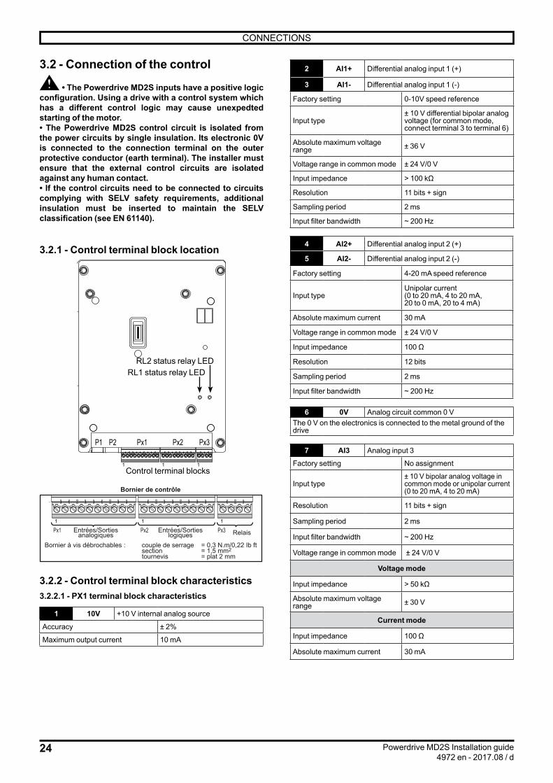
3.2 - Connection of the control
• The Powerdrive MD2S inputs have a positive logic configuration. Using a drive with a control system which has a different control logic may cause unexpedted starting of the motor.• The Powerdrive MD2S control circuit is isolated from the power circuits by single insulation. Its electronic 0V is connected to the connection terminal on the outer protective conductor (earth terminal). The installer must ensure that the external control circuits are isolated against any human contact.• If the control circuits need to be connected to circuits complying with SELV safety requirements, additional insulation must be inserted to maintain the SELV classification (see EN 61140).
3.2.1 - Control terminal block location
Px1 Px2 Px3P1 P2
1 1 1
RL2 status relay LEDRL1 status relay LED
Control terminal blocks
Px1 Px2 Px31 1 1
Bornier de contrôle
Bornier à vis débrochables : couple de serrage = 0,3 N.m/0,22 Ib ft section = 1,5 mm2 tournevis = plat 2 mm
Entrées/Sortiesanalogiques
Entrées/Sortieslogiques Relais
3.2.2 - Control terminal block characteristics3.2.2.1 - PX1 terminal block characteristics
1 10V +10 V internal analog source
Accuracy ± 2%
Maximum output current 10 mA
2 AI1+ Differential analog input 1 (+)
3 AI1- Differential analog input 1 (-)
Factory setting 0-10V speed reference
Input type± 10 V differential bipolar analog voltage (for common mode, connect terminal 3 to terminal 6)
Absolute maximum voltage range ± 36 V
Voltage range in common mode ± 24 V/0 V
Input impedance > 100 kΩ
Resolution 11 bits + sign
Sampling period 2 ms
Input filter bandwidth ~ 200 Hz
4 AI2+ Differential analog input 2 (+)
5 AI2- Differential analog input 2 (-)
Factory setting 4-20 mA speed reference
Input typeUnipolar current (0 to 20 mA, 4 to 20 mA, 20 to 0 mA, 20 to 4 mA)
Absolute maximum current 30 mA
Voltage range in common mode ± 24 V/0 V
Input impedance 100 Ω
Resolution 12 bits
Sampling period 2 ms
Input filter bandwidth ~ 200 Hz
6 0V Analog circuit common 0 VThe 0 V on the electronics is connected to the metal ground of the drive
7 AI3 Analog input 3
Factory setting No assignment
Input type± 10 V bipolar analog voltage in common mode or unipolar current (0 to 20 mA, 4 to 20 mA)
Resolution 11 bits + sign
Sampling period 2 ms
Input filter bandwidth ~ 200 Hz
Voltage range in common mode ± 24 V/0 V
Voltage mode
Input impedance > 50 kΩ
Absolute maximum voltage range ± 30 V
Current mode
Input impedance 100 Ω
Absolute maximum current 30 mA
25
CONNECTIONS
Powerdrive MD2S Installation guide4972 en - 2017.08 / d
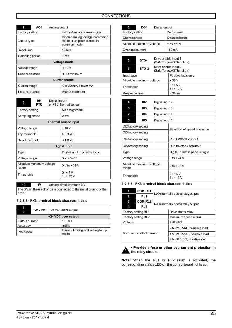
8 AO1 Analog outputFactory setting 4-20 mA motor current signal
Output typeBipolar analog voltage in common mode or unipolar current in common mode
Resolution 13 bits
Sampling period 2 ms
Voltage mode
Voltage range ± 10 V
Load resistance 1 kΩ minimum
Current mode
Current range 0 to 20 mA, 4 to 20 mA
Load resistance 500 Ω maximum
9 DI1 PTC
Digital input 1 or PTC thermal sensor
Factory setting No assignment
Sampling period 2 ms
Thermal sensor input
Voltage range ± 10 V
Trip threshold > 3.3 kΩ
Reset threshold < 1.8 kΩ
Digital input
Type Digital input in positive logic
Voltage range 0 to + 24 V
Absolute maximum voltage range 0 V to + 35 V
Thresholds 0 : < 5 V1 : > 13 V
10 0V Analog circuit common 0 VThe 0 V on the electronics is connected to the metal ground of the drive
3.2.2.2 - PX2 terminal block characteristics
1+24V ref +24 VDC user output
9+24 VDC user output
Output current 100 mAAccuracy ± 5%
Protection Current limiting and setting to trip mode
2 DO1 Digital output Factory setting Zero speed
Characteristic Open collector
Absolute maximum voltage + 30 V/0 V
Overload current 150 mA
3 STO-1 Drive enable input 1(Safe Torque Off function)
6 STO-2 Drive enable input 2(Safe Torque Off function)
Input type Positive logic onlyAbsolute maximum voltage + 30 V
Thresholds 0 : < 5 V1 : > 13 V
Response time < 20 ms
4 DI2 Digital input 2
5 DI3 Digital input 3
7 DI4 Digital input 4
8 DI5 Digital input 5
DI2 factory settingSelection of speed reference
DI3 factory setting
DI4 factory setting Run FWD/Stop input
DI5 factory setting Run reverse/Stop input
Type Digital inputs in positive logic
Voltage range 0 to + 24 V
Absolute maximum voltage range 0 to + 35 V
Thresholds 0 : < 5 V1 : > 13 V
3.2.2.3 - PX3 terminal block characteristics
1 COM-RL1N/O (normally open) relay output
2 RL13 COM-RL2
N/O (normally open) relay output4 RL2
Factory setting RL1 Drive status relay
Factory setting RL2 Maximum speed alarm
Voltage 250 VAC
Maximum contact current
2 A - 250 VAC, resistive load
1 A - 250 VAC, inductive load
2 A - 30 VDC, resistive load
• Provide a fuse or other overcurrent protection in the relay circuit.
Note: When the RL1 or RL2 relay is activated, the corresponding status LED on the control board lights up.

26
CONNECTIONS
Powerdrive MD2S Installation guide4972 en - 2017.08 / d
3.2.3 - Factory configuration of control terminal blocksNota : For more details on the parameters, please refer to the commissioning manual ref.4617
+10V ref
AI1+
AI1-
AI2+
AI2-
0V
COM-RL1
RL1
COM-RL2
RL2
AO1
AI3
+24V ref
DO1
STO-1
DI2
DI3
STO-2
DI5
DI4
+24V ref
1
2
3
4
5
6
1
2
3
4
8
7
0V
DI1/CTP
10
9
1
2
3
4
5
6
8
7
9
PX1
PX2
PX3
Status relay (**)Drive healthy (N/O)
Alarm relaymaximum speed (N/O)
0-10 V speed reference
4-20 mA speed reference
4-20 mA current image
Motor PTC (*)
Zero speedSafe Torque Off/
Drive enable input 1Reference selection
Reference selection
Safe Torque Off/Drive enable input 2
Run FWD/Stop
Run REV/Stop
Note: This configuration has been obtained from a drive with factory settings (default parameter settings).The STO-1 and STO-2 inputs must be closed before giving a run command.
(*) If the motor thermal sensor needs to be connected to DI1/PTC, set Mtr.06 (05.70) = Drive terminal (1).
(**) If the 2 STO inputs are not in the same status, the relay RL1 opens.
• Modification of the Run/Stop control logic - For "3-wire" control (jog Run/Stop):
DI4
DI5
+24V ref
7
8
9
Run FWD
Stop
List of parameters to set: Ctr.06 (06.04) = Run Latched (1) I/O.10 (08.25) = 06.39 Stop (DI5 terminal)
- For Run/Stop control with change of direction:
DI4
DI5
+24V ref
7
9
8
Run/Stop
Change of direction
List of parameters to set: Ctr.06 (06.04) = Run Fwd/Rev (2) I/O.09 (08.24) = 06.34 Run/Stop (DI4 terminal) I/O.10 (08.25) = 06.33 Fwd/Reverse (DI5 terminal)
• Selection of the reference via digital inputs:
DI2 DI3 Selection
0 0 Voltage speed reference (0-10 V) on analog input AI1+, AI1-
0 1 Current speed reference (4-20 mA) on analog input AI2+, AI2-
1 0 Preset reference 2Spd.05 (01.22) to be set1 1

27
CONNECTIONS
Powerdrive MD2S Installation guide4972 en - 2017.08 / d
3.3 - STO-1/STO-2 inputs: Safe Torque Off functionThe STO-1 and STO-2 inputs are safety inputs that can be used to disable the drive output so no torque at the motor shaft is generated. They are independent of one another. They are created by simple hardware not connected to the microcontroller. They act on two different stages of the IGBT output bridge control.To enable the drive, the STO-1 and STO-2 inputs must be connected to the +24V source.The opening of a minimum of one input locks the output bridge.
These 2 inputs can be used in conjunction to create a "Safe Torque Off" function with a logic combining 2 separate channels.In this configuration, the "Safe Torque Off" function is guaranteed with a very high level of integrity in conformity with standards: - EN 61800-5-2 - EN/ISO 13849-1: 2006; PLe - IEC/EN 62061: 2005; SIL3(CETIM approval no. CET0047520)
This built-in function enables the drive to act as a contactor that switches off the motor power, allowing a deceleration in a free wheel mode. This corresponds to an uncontrolled stop in accordance with stop category 0 og IEC 60204-1.
The STO-1 and STO-2 inputs are compatible with self-tested logic outputs in controllers such as PLCs, for which the test pulse lasts for 1 ms maximum.If the data sent by the 2 inputs are not identical, this generates a drive trip. The RL1 relay opens and the drive indicates a "t.r./63" trip on the drive 2-digit display or "STO input inconsistency" trip on the parameter-setting interface.
For correct use, the power and control connection diagrams described in the following paragraphs must be adhered to.
• The STO-1/STO-2 inputs are safety components which must be incorporated in the complete system dedicated to machine safety. As for any
installation, the complete machine must be subject to a risk analysis. The integrator must determine the safety category which the installation must comply with.• The STO-1 and STO-2 inputs, when open, lock the drive, so the dynamic braking function is no longer available. If a braking function is required before the drive secure disable lock is applied, a time-delayed safety relay must be installed to activate the locking automatically after the end of braking.If braking needs to be a machine safety function, it must be provided by an electromechanical solution since the dynamic braking by the drive function is not considered as a secure disable function.• The STO-1/STO-2 inputs do not provide the electrical isolation function. Prior to any work carried out on the drive / installation, the power supply must therefore be switched of through an approved isolating device (isolator, switch, etc).• The line switch integrated as an option in the drive does not isolate the drive input busbars. During the installation and maintenance phases, make sure that the power supply line is disrupted.
3.3.1 - Single channel locking (SIL1 - PLb)3-phase AC power supply, in accordance with safety standard IEC/EN 62061: 2005 and EN/ISO 13849-1: 2006 - Single channel locking (SIL1 - PLb).
U V W
Px2+24V RefDO1STO-1DI2DI3STO-2DI4DI5+24V Ref
M3
PE
PEL1 L2 L3
Safe Torque Off/Drive enable input
Run FWD/StopRun REV/Stop
3.3.2 - Double channel locking (SIL3 - PLe).3-phase AC power supply, in accordance with safety standard IEC/EN 62061: 2005 and EN/ISO 13849-1: 2006 - Double channel locking (SIL3 - PLe)
U V W
Px2+24V RefDO1STO-1DI2DI3STO-2DI4DI5+24V Ref
M3
PE
PEL1 L2 L3
Output stage of a safety relay
Run FWD/StopRun REV/Stop

28
GENERAL EMC - HARMONICS - MAINS INTERFERENCE
Powerdrive MD2S Installation guide4972 en - 2017.08 / d
4 - GENERAL EMC - HARMONICS - MAINS INTERFERENCEThe power structure of frequency inverters leads to the occurrence of two types of phenomenom :- Low-frequency harmonics fed back to the mains supply- Emission of radio-frequency signals (RFI)These are independent phenomena. They have different consequences on the electrical environment.
4.1 - Low-frequency harmonicsThe rectifier, at the head of the frequency inverter, generates a non-sinusoidal AC line current.
3-phase rectifier line current consumption.
This current carries harmonics with number 6n ± 1.Their amplitudes depend on the impedance of the mains supply upstream the rectifier bridge, and on the structure of the DC bus downstream the rectifier bridge.The more inductive the mains supply and the DC bus, the more these harmonics are reduced.They only affect the quality of the mains supply for loads on frequency inverters of several hundred kVA, if these loads represent more than a quarter of the total load on a site.In the above conditions: • These harmonics have virtually no effect on the electrical energy consumption level. • The associated temperature rises in transformers and motors directly connected to the mains supply are negligible.It is very rare for these low-frequency harmonics to cause interference on sensitive equipment.
4.2 - Radio-frequency interference: Immunity4.2.1 - GeneralThe immunity level of a device is defined by its ability to operate in an environment which is contaminated by external elements or by its electrical connections.
4.2.2 - StandardsEach device must undergo a series of standard tests (European standards) and meet a minimum requirement in order to be declared as compliant with the variable speed drive standards (EN 61800-3).
4.2.3 - RecommendationsAn installation consisting exclusively of devices which comply with the standards concerning immunity is very unlikely to be subject to a risk of interference.
4.3 - Radio-frequency interference: Emission4.3.1 - GeneralIn order to limit motor losses and obtain a low level of motor noise, frequency inverters use high-speed switches (transistors, semi-conductors) which switch high voltages (> 550 V) at high frequencies (several kHz). As a result, they generate radio-frequency (R.F.) signals which may disturb operation of other equipments or distort measurements taken by sensors:• Due to high-frequency leakage currents which escape to earth via the stray capacity of the drive/motor cable and through the motor via the metal structures which support it.• By conduction or feedback of R.F. signals on the power supply cable: conducted emissions• By direct radiation near to the mains supply power cable or the drive/motor cable: radiated emissions.These phenomena are of direct interest to the user.The frequency range concerned (radio frequency) does not affect the energy distribution company.
4.3.2 - StandardsStandard EN 61800-3 defines the maximum emission levels to comply with according to the type of environment the drive is installed in. In some cases, it may be necessary to add an external RFI filter (see section 4.6).
29
GENERAL EMC - HARMONICS - MAINS INTERFERENCE
Powerdrive MD2S Installation guide4972 en - 2017.08 / d
4.4 - Mains supply4.4.1 - GeneralEach industrial power supply has its own intrinsic characteristics (short-circuit capability, voltage value and fluctuation, phase imbalance, etc) and supplies equipment some of which can distort its voltage either permanently or temporarily (notches, voltage dips, overvoltage, etc). The quality of the mains supply has an impact on the performance and reliability of electronic equipments, especially variable speed drives.The Powerdrive MD2S is designed to operate with mains supplies typical of industrial sites throughout the world. However, for each installation, it is important to know the characteristics of the mains supply in order to carry out corrective measures in the event of abnormal conditions.
4.4.2 - Mains transient overvoltagesThere are numerous sources of overvoltages on an electrical installation:• Connection/disconnection of banks of power factor correction capacitors• High-power thyristor-controlled equipment (oven, DC drive, etc)• Results of lightning
4.4.2.1 - Connection/disconnection of a bank of power factor correction capacitors Connecting power factor correction capacitors in parallel on the drive power supply line when the drive is running can generate transient overvoltages that are likely to trip the drive safety devices, or even damage it in extreme cases.If banks of power factor correction capacitors are used on the power supply line, make sure that:• The threshold between steps is low enough to avoid causing overvoltage on the line• The capacitors are not permanently connected
4.4.2.2 - Presence of commutation notches on the lineWhen high-power thyristor-controlled equipment is connected on the same line as the drive, it is essential to ensure that the harmonics generated by the commutation notches do not excessively distort the mains voltage and do not create voltage peaks with amplitude higher than 2 x mains Vrms. If this is the case, it is essential to take corrective measures by inserting a choke in the line supplying the thyristor-controlled equipment or by moving the drive power supply line to another source.
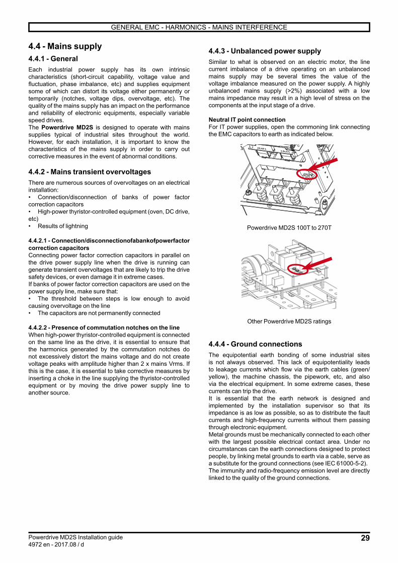
4.4.3 - Unbalanced power supplySimilar to what is observed on an electric motor, the line current imbalance of a drive operating on an unbalanced mains supply may be several times the value of the voltage imbalance measured on the power supply. A highly unbalanced mains supply (>2%) associated with a low mains impedance may result in a high level of stress on the components at the input stage of a drive.
Neutral IT point connectionFor IT power supplies, open the commoning link connecting the EMC capacitors to earth as indicated below.
Powerdrive MD2S 100T to 270T
Other Powerdrive MD2S ratings
4.4.4 - Ground connectionsThe equipotential earth bonding of some industrial sites is not always observed. This lack of equipotentiality leads to leakage currents which flow via the earth cables (green/yellow), the machine chassis, the pipework, etc, and also via the electrical equipment. In some extreme cases, these currents can trip the drive.It is essential that the earth network is designed and implemented by the installation supervisor so that its impedance is as low as possible, so as to distribute the fault currents and high-frequency currents without them passing through electronic equipment.Metal grounds must be mechanically connected to each other with the largest possible electrical contact area. Under no circumstances can the earth connections designed to protect people, by linking metal grounds to earth via a cable, serve as a substitute for the ground connections (see IEC 61000-5-2).The immunity and radio-frequency emission level are directly linked to the quality of the ground connections.

30
GENERAL EMC - HARMONICS - MAINS INTERFERENCE
Powerdrive MD2S Installation guide4972 en - 2017.08 / d
4.5 - Basic precautions for installation These should be taken into account when wiring the Powerdrive MD2S and the external components. In each paragraph, they are listed in decreasing order of effect on correct operation of the installation.
4.5.1 - Wiring inside the cabinet- Separate as far as possible control cables and power cables (Do not run them in the same cable ducts).- For control cables, use shielded twisted cables and connect the shield to the grounding bracket..The bracket for connecting the option shielding is suppliedwith each option. To attach it, screw the bracket, placing it ontop of the control cable shielding clamps (the shielding clampfurthest to the right should be removed).
Grounding bracket of the options
Grounding bracket
4.5.2 - Wiring outside the cabinet4.5.2.1 - Control wiringIf the control cable needs to run outside the cabinet, use a shielded cable and connect the shield to the grounding bracket.
4.5.2.2 - Power wiring• Connect the motor earth terminal directly to that of the drive.
Never use shielded single-core cables
Use shielded 3-core cables with symmetrical conductors for protective earthing as indicated below.The shield must be connected at both ends: drive end and motor end (connected round the whole circumference).
U
WVPE
PE PE
Shielding
A separate PE protective conductor is mandatory if the conductivity of the cable shielding is less than 50% of the conductivity of the phase conductor. - The shielding must be connected at both ends: drive end and motor end (connected round the whole circumference). - In the second industrial environment, the shielded motor power supply cable can be replaced by a 3-core + earth cable placed in a fully enclosed metal conduit (metal cable duct for example). This metal conduit must be mechanically connected to the electrical cabinet and the structure supporting the motor.
If the conduit consists of several pieces, these should be interconnected by braids to ensure earth continuity. The cables must be positioned and held in a cloverleaf formation in the conduit.
U
WVPE
U
WVPE
EMC braid
Clamp
- There is no need to shield the power supply cables between the mains supply and the drive.- Isolate the power cables from the control cables. The power cables must intersect the other cables at an angle of 90°.- Isolate sensitive elements (probes, sensors, etc) from metal structures which may be shared by the motor support.- The motor cables and network power cables should not be routed side by side in the same channel to reduce proximity couplings.

31
GENERAL EMC - HARMONICS - MAINS INTERFERENCE
Powerdrive MD2S Installation guide4972 en - 2017.08 / d
4.6 - Electromagnetic compatibility (EMC)CAUTION:Conformity of the drive is only assured when the mechanical and electrical installation instructions described in this manual are adhered to.
Immunity
Standard Description Application Conformity
IEC 61000-4-2Electrostatic discharges Product casing Level 3 (industrial)
EN 61000-4-2
IEC 61000-4-3 Immunity standards for radiated radio-frequency Product casing Level 3 (industrial)
EN 61000-4-3
IEC 61000-4-4Bursts of fast transients
Control cable Level 4 (industrially hardened)
EN 61000-4-4 Power cable Level 3 (industrial)
IEC 61000-4-5Shock waves Power cables Level 4
EN 61000-4-5
IEC 61000-4-6 Generic immunity standards for conducted radio-frequency
Control and power cables Level 3 (industrial)
EN 61000-4-6
EN 50082-2Generic immunity standards for the industrial environment - ConformingIEC 61000-6-2
EN 61000-6-2
EN 61800-3
Variable speed drive standards Conforming to the first and second environmentIEC 61800-3
EN 61000-3
Emission
Standard Description CatégoryConformity conditions
Standard With optional RFI filter
EN 61800-3 Variable speed drive standards
C1 - -
C2 -Conforming
- Cable length < 10 m- Switching frequency < 4 kHz
C3Conforming
- Cable length < 100 m- Switching frequency < 4 kHz
Conforming- Cable length < 100 m- Switching frequency < 6 kHz

32
PARAMETER-SETTING INTERFACE AND OPTIONS
Powerdrive MD2S Installation guide4972 en - 2017.08 / d
5.1.2 - MDX-Powerscreen• GeneralThe POWERSCREEN interface is a touch screen which can be used to access various menus to setup and supervise the drive. It is installed as standard on the POWERDRIVE MD2S.
After the loading phase following the power-up of the drive, the parameter-setting interface displays the screen below in french. Select language using the "F" buttons below
COM CPU PWR
F
C D E
A
B
Ref. FunctionA 4.3" touch screen
B Touch-sensitive button to access the main menu
C
"COM" LED, indicates the state of the communication with the drive. Off: no communication Flashing: communicating
D "CPU" LED, indicates the status of the interface CPU
E "PWR" LED, indicates the state of the interface power supply
F Touch-sensitive buttons for language selection (can take a few minutes to load)
5 - PARAMETER-SETTING INTERFACE AND OPTIONS
5.1 - Parameter setting interfaces5.1.1 - Location of the drive connectors / ports
Px1 Px2 Px3P1 P2
1 1 1
Connector for optional fieldbus and/or speed feeback
Connector for
MDX-Powerscreen display
USB connector linked to door USB socket
◦ P1 connectorThis connector is a slave type B USB connector linked to door USB socket, and is used to communicate via PC using the MDX-SOFT software.
In conformity with standard EN 60950, the USB link can only be used via a device that provides
isolation of 4 kV (MDX-USB isolator option).
◦ P2 terminal blockThis is a standard RS485/RS422 terminal block which is used to connect a parameter-setting interface (MDX Powerscreen, MDX Keypad) or to communicate via Modbus RTU.
Terminals Description1 0V2 Rx\, Tx\3 Rx, Tx4 24V
Check that control circuits are powered down before disconnecting the programming interface
from the P2 connector.
33
PARAMETER-SETTING INTERFACE AND OPTIONS
Powerdrive MD2S Installation guide4972 en - 2017.08 / d
• ArchitectureFrom the welcome screen, press the button to access the main page of the parameter-setting interface, consisting of 5 touch-sensitive buttons:- Information: Can be used to obtain information very quickly about the drive, the fieldbus option, the parameter-setting interface, and can also be used to select the language.- Read mode: Is used to display the status of the drive when stopped or in operation, as well as its main operating data.- Parameter setting: Used for reading and/or modifying all the drive parameters, as well as setting the date and time on the display.- Control via keypad: Gives direct access to motor control via the touch screen (Run/Stop, direction of rotation, speed reference). These screen parameters can be set using the Parameter setting/Parameter setting via the keypad menu. Control via the keypad is disabled in factory-set configuration.- Trip history: Gives a quick overview of the last 10 drive trips.- : This button is accessible on all screens in factory-set configuration and is used to give a stop command (can be disabled).
At any time and regardless of the screen displayed, the button can be used to return to previous pages, as far as the interface main page.
For further information, see the commissioning manual ref. 4617.
5.1.3 - MDX-SOFTThe MDX-SOFT enables parameter setting or supervision of the Powerdrive MD2S from a PC. Numerous functions are available:- Fast commissioning- File saving- Comparison of 2 files or one file with the factory settings- Printing of a complete file or differences compared to the factory settings- Supervision- Diagnostics
To connect the PC to the Powerdrive MD2S, use an "MDX-USB Isolator" isolated USB cable.
This software can be downloaded from the web at the following address: http://www.emersonindustrial.com/
Powerdrive MD2S can be set via the USB connector, even if the drive is not powered.Attention. In this case, options modules will not be powered and settings will not be saved. To make an option module setting / backup , it is necessary to provide an auxiliary power supply.
Special settings
Refer to the installation manual of (ref. 4617) for details on settings.
• Clogged filter alarmPowerdrive MD2S has an "overtemperature" alarm (# 10.18) which warns the user when the internal temperature of the product reaches 60°C or when a power module overheats.To set a different alarm treshold, you can use the following settings:Using comparator 3: #12.63 = 7.55 (source = control board temperature) #12.64 = 60 (threshold = 60 ° C) #12.65 = 2°C (hysteresis) #12.65 = 0To display information on the HMI of the drive: #12.67 = 10.54 (User Alarm 1)To adress information to a digital output (eg. DO1) # 8.26 = 12.61 (DO1 assigned to comparator 3)
Reminder: Powerdrive MD2S filters are washable and must be kept clean. See § 7 - Maintenance

34
PARAMETER-SETTING INTERFACE AND OPTIONS
Powerdrive MD2S Installation guide4972 en - 2017.08 / d
5.2 - Add-on optionsThe control board is designed to be plugged with various optional modules. Several options can be combined:• Fieldbus (see section 5.2.1)• Speed feedback (see section 5.2.2)• Additionnal I/O (see section 5.2.3)
5.2.1 - Fieldbus modulesDepending on the configuration of the speed feedback and inputs/outputs optional modules, two types of fieldbus are proposed:
MDX option: option to be fitted to the control board
CM module: compact module to be integrated in an existing MDX board
Association table :
Main optionFiledbus
MDX version CM versionNone
MDX-ENCODER X
MDX-RESOLVER X
MDX-I/O Lite X
MDX I/O M2M X
MDX-ENCODER + MDX I/O M2M X
MDX-RESOLVER + MDX I/O M2M X
Fieldbus modules can be used to communicate with the corresponding networks respective. They can be integrated in and are supplied by the drive.
The following fieldbus are available on Powerdrive MD2S :
• MDX/CM-MODBUS : Modbus RTU (RS485/232)• MDX/CM-ETHERNET : Modbus TCP (Ethernet)• MDX/CM-ETHERNET-IP : EtherNet/IP• MDX/CM-PROFIBUS : Profibus DP V1• MDX/CM-PROFINET : ProfiNet
For more details, consult the specific documentations.
5.2.2 - Speed feedback options
Two options are available to manage the motor speed feedback. :
• MDX-ENCODER: The MDX-ENCODER option is used to It manages incremental encoders with or without commuation channels (up to 500kHz).
• MDX-RESOLVER: The MDX-RESOLVER option is used to manage 2 to 8 poles resolvers.
For more details, consult the specific documentations.
5.2.3 - Additionnal I/O optionsTwo options are available to increase the Powerdrive MD2S number of inputs and outputs :
MDX-I/O LITE MDX-I/O M2M
Fonctions MDX-I/O Lite
MDX-I/O M2M
Analog input (V, mA) - 1
Differential analog input (V, mA) 1 1
Analog ouputs (V, mA) 2 1
Motor thermistorKTY84-130 or PT100 1 1
Digital inputs 2 4
Digital outputs 1 2
Assignable relay 1 2
Drive forced fan's management
Real time clock -
Ethernet connection :• WEB pages: drive configuration
and status• 2 Programmable emails• Configuration backup & restoration
-
Datalogger -
For more details, consult the specific documentations.

35
PARAMETER-SETTING INTERFACE AND OPTIONS
Powerdrive MD2S Installation guide4972 en - 2017.08 / d
5.3 - Electrical protectionIn the factory, an isolating device can be incorporated into the Powerdrive MD2S.
The AC supply switchgear integrated as an option in the drive does not isolate the drive input busbars.
During the installation and maintenance phases, make sure that the power supply line is open circuit.The references and dimensions of the options below, mounted in a Powerdrive MD2S, are given on the LEROY-SOMER configurator: http://configurateurls.leroy-somer.com
5.3.1 - SwitchA 3-pole switch is available for the Powerdrive MD2S. This option is used to isolate the motor from the AC supply during maintenance operations.• Fully visible break with padlockable handle on the front of the drive cabinet (can be turned manually, padlock not supplied)• Conforming to standard IEC/EN 60947-3The QS3P switch must always be included in aR semi-conductor fuse kits, in accordance with the table in section 3.1.5.
Characteristics at 40°C in category AC21Ith = thermal current
RatingSwitch
ReferenceIth @ 400 V
(A)
Ith @ 690 V
(A)
Number of operations
150T to 150T QS3P_250A 250 250 10,000
180T and 220TQS3P_400A 400 400 5,000
270TH and 340TH
270T to 340TQS3P_630A 630 630 5,000
400TH to 600TH
400TQS3P_800A 800 800 3,000
750TH
470T to 600T QS3P_1000A 1000 800 3,000
750TQS3P_1250A 1250 1000 4,000
900TH
900T QS3P_1600A 1600 1000 4,000
1100T QS3P_1800A 1800 1000 4,000
1400T and 1700TPlease consult Leroy-Somer
1200TH to 1500TH
The dimensions of a Powerdrive MD2S equipped with a switch is described in section2.6.
5.3.2 - Emergency stop• MD-AU 1: SIL1/PLb protection deviceThe MD-AU 1 protection device consists of an emergency stop wired on the STO inputs and mounted on the front.• SIL3/PLe protection deviceThe Powerdrive MD2S can be made compatible with SIL3/PLe by incorporating a safety relay for double channel locking.Contact LEROY-SOMER.
5.4 - Heater kitTo prevent condensation in the Powerdrive MD2S a self-limited temperature heater is available as an option.The connection is made on a dedicated terminal (see below).The intaller must provide ~230V single phase protection (fuse rating indicated below) and ensure its control (the module must be turned off when the drive is in operation).
Reference Pn (W) Max current (A)
Time delay fuse (A)
MD2HEAT2 150 9 6,3
Ratings 100T to 270T Other ratings
5.5 - RFI filterThe use of RFI filters helps reduce the emission levels of conducted and radiated radio-frequency signals. They ensure that Powerdrive MD2S components conform to variable speed drive standard EN61800-3.Depending on the drive used, install the RFI filter recommended in the table below between the AC supply and the drive input.
Powerdrive MD2S rating
RFI filter
Reference Irated at 40°C (A)
Leakage current
(mA)
Losses(W)
100T FN 3359 HV-180 197 <6 34
120T to 150T FN 3359 HV-250 250 <6 49
270TH FN 3359 HV-320 350 <6 19
180T and 220TFN 3359 HV-400 438 <6 29
340TH
270T to 400TFN 3359 HV-600 657 <6 44
400TH to 600TH
470T to 600TFN 3359 HV-1000 1095 <6 60
750TH to 900TH
750T to 1100TFN 3359 HV-1600 1600 <6 1311200TH and
1500TH
1400T and 1700T FN 3359 HV-2500 2500 <6 300
WARNING:The specific design of these filters makes it possible to use them in the context of installations with a neutral IT point connection. The installer should, however, ensure that insulation monitoring systems dedicated to these installations are suitable for monitoring electrical equipment that may contain electronic variable speed drives.
MD2HEATterminals
MD2-AUterminals
MD2HEATterminals
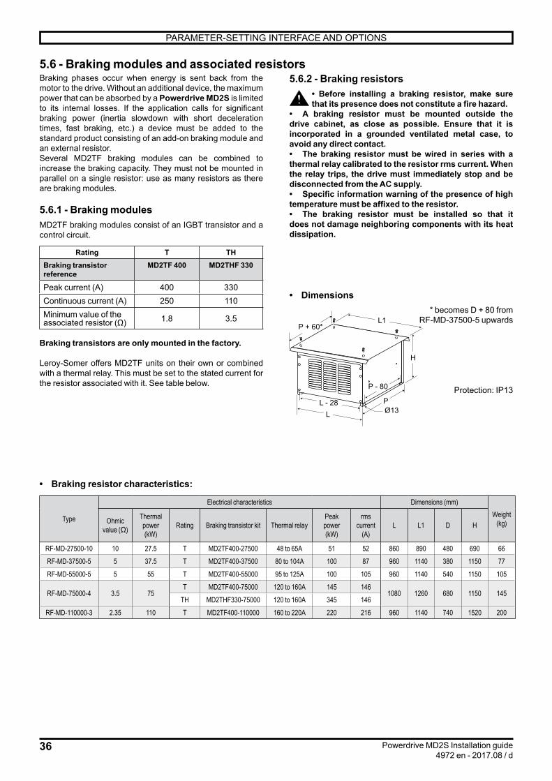
36
L1
H
P
P - 80
P + 60*
Ø13L - 28
L
PARAMETER-SETTING INTERFACE AND OPTIONS
Powerdrive MD2S Installation guide4972 en - 2017.08 / d
5.6.2 - Braking resistors• Before installing a braking resistor, make sure that its presence does not constitute a fire hazard.
• A braking resistor must be mounted outside the drive cabinet, as close as possible. Ensure that it is incorporated in a grounded ventilated metal case, to avoid any direct contact.• The braking resistor must be wired in series with a thermal relay calibrated to the resistor rms current. When the relay trips, the drive must immediately stop and be disconnected from the AC supply.• Specific information warning of the presence of high temperature must be affixed to the resistor.• The braking resistor must be installed so that it does not damage neighboring components with its heat dissipation.
• Dimensions* becomes D + 80 from
RF-MD-37500-5 upwards
Protection: IP13
Braking phases occur when energy is sent back from the motor to the drive. Without an additional device, the maximum power that can be absorbed by a Powerdrive MD2S is limited to its internal losses. If the application calls for significant braking power (inertia slowdown with short deceleration times, fast braking, etc.) a device must be added to the standard product consisting of an add-on braking module and an external resistor. Several MD2TF braking modules can be combined to increase the braking capacity. They must not be mounted in parallel on a single resistor: use as many resistors as there are braking modules.
5.6.1 - Braking modulesMD2TF braking modules consist of an IGBT transistor and a control circuit.
Rating T THBraking transistor reference
MD2TF 400 MD2THF 330
Peak current (A) 400 330Continuous current (A) 250 110Minimum value of the associated resistor (Ω) 1.8 3.5
Braking transistors are only mounted in the factory.
Leroy-Somer offers MD2TF units on their own or combined with a thermal relay. This must be set to the stated current for the resistor associated with it. See table below.
• Braking resistor characteristics:
Type
Electrical characteristics Dimensions (mm)Weight
(kg)Ohmic value (Ω)
Thermal power(kW)
Rating Braking transistor kit Thermal relayPeak power(kW)
rms current
(A)L L1 D H
RF-MD-27500-10 10 27.5 T MD2TF400-27500 48 to 65A 51 52 860 890 480 690 66RF-MD-37500-5 5 37.5 T MD2TF400-37500 80 to 104A 100 87 960 1140 380 1150 77RF-MD-55000-5 5 55 T MD2TF400-55000 95 to 125A 100 105 960 1140 540 1150 105
RF-MD-75000-4 3.5 75T MD2TF400-75000 120 to 160A 145 146
1080 1260 680 1150 145TH MD2THF330-75000 120 to 160A 345 146
RF-MD-110000-3 2.35 110 T MD2TF400-110000 160 to 220A 220 216 960 1140 740 1520 200
5.6 - Braking modules and associated resistors

37
PARAMETER-SETTING INTERFACE AND OPTIONS
Powerdrive MD2S Installation guide4972 en - 2017.08 / d
5.7 - Internal wiring schemes for the options
The internal wiring schemes for the Powerdrive MD2S for the options described in the preceding pages are illustrated on the next 4 pages.

= +
M3
UVW
M1
EXTE
RNAL
BREA
KING
RESI
STO
RR
ESIS
TAN
CE
FREI
NAG
EEX
TERN
E
TYPE
RESI
STAN
CE
RES
ISTO
RTY
PE
RF-
MD
-275
00-1
0
OHM 10
PkW
27.5
RF-
MD
-375
00-5
537
.5
RF-
MD
-550
00-5
555
RF-
MD
-750
00-4
3.5
75
RF-
MD
-110
00-3
2.35
110
52
AR
MS
87 105
146
216
1
2
1
2
1
2M
NL
CONT
RO
LM
ODU
LEM
OD
ULE
DEC
ONT
RO
LE
(9)
-APA
(3)
(6)PX
2
X111
X1X111
X1
L N
M
(a)
(b)
(c)
(d)
01.0
4
01.0
4
01.0
4
3PHASESNETWORK
(ES
:YES
/OUI
-BT
:NO
/NO
N)
(ES
:NO
/NO
N-B
T:N
O/N
ON)
fuse
sbo
ard
Carte
fusi
bles
/
INTE
R-SE
CTIO
NNEU
R:
CIRC
UIT
BREA
KER
:FI
LTRE
CEM
:EM
CFI
LTER
:TR
ANSI
STO
RDE
FREI
NAG
E+
RELA
ISTH
ERM
IQU
E*:
BRAK
ING
TRAN
SIST
OR
+TH
ERM
ALRE
LAY
*:BO
UTO
NAR
RET
D'U
RGEN
CE:
EMER
GEN
CYST
OP
BUTT
ON
:
01.0
4
OPT
IONS
REPR
ESEN
TEES
SUR
CESC
HEM
ADE
CABL
AGE:
OPT
IONS
SHO
WN
INTH
ISW
IRIN
GDI
AGR
AM:
MD2TF
RESEAUTRIPHASE
MDX
IO
Moduledecontrole/controlmodule
PX2
(a)
(b)
(*)Vo
irla
notic
ed'
inst
alla
tion
pour
lalo
calis
atio
nSe
eth
ein
stal
latio
nm
anua
lfor
loca
lizat
ion
(HR)
Carte
fusi
bles
/fu
ses
boar
d
Sousensembleredresseur-onduleurRectifier-invertersubassembly
DO2
24VD
C
MDX
IO
(c)
(d)
Arm
oire
stan
dard
deba
se/S
tand
ard
base
prod
uct
AVEC
YES
GES
TIO
NDE
SVE
NTIL
ATIO
NS:
MD2
FAN
CONT
RO
LKI
T:
AVEC
YES
AVEC
/SAN
SYE
S/N
OAV
EC/S
ANS
YES
/NO
AVEC
/SAN
SYE
S/N
O
PX1 PX3
100-
270T
Carte
fusi
bles
/fu
ses
boar
dP7 P8
340-
570T
OPT
ION
RESI
STAN
CE
DER
ECHA
UFFA
GE
HEAT
ING
RESI
STO
R
OPT
ION
COUR
ANT
D'AP
PEL
9AIN
RU
SHC
URR
ENT
9A
HEAT
ING
RES
ISTO
R:
YES
/NO
RESI
STAN
CEDE
RECH
AUFF
AGE
:AV
EC/S
ANS
0V 24VD
CM
DXIO
Carte
fusi
bles
/fu
ses
boar
dP7 P8
+ -
+ -
(CB)
(FCK
)
230V
150W
(FLT
)
(BT)
(ES)
(FCK
)
(HR)
(CB)
(FLT
)
(BT)
(*)
(ES
:YES
/OUI
-BT
:YES
/OUI
)
(ES
:NO
/NO
N-B
T:Y
ES/O
UI)
12
X1SE
CUR
ITE
EXTE
RIEU
REX
TERN
ALSE
CURI
TY2 1
2X1
SECU
RIT
EEX
TERI
EUR
EXTE
RNAL
SECU
RITY
12 1
2X1
SECU
RIT
EEX
TERI
EUR
EXTE
RNAL
SECU
RITY
22
1
21
2X1
22
SECU
RIT
EEX
TERI
EUR
-S1
EXTE
RNAL
SECU
RITY
2
01.1
0
L2 L1L3
RL1
1
SL1
2
TL1
3
PE
01.1
2
01.1
3
01.1
1
01.1
0
01.1
1
01.0
4
01.0
10,
75²-B
LEU_
FONC
E
01.0
10,
75²-B
LEU_
FONC
E
01.0
2
01.0
10,
75²-B
LEU_
FONC
E
01.0
2
01.0
301
.02
01.0
1
N
01.0
10,
75²-B
LEU_
FONC
EPE1
L
BR1
BR2
BR4
L21
BR4
L22
BR3
-F10 01
-9
-F10 01
-9
21
22
-S1
-Q1
-F10
1 2
3 4
5 6
NF/0
1-3
NF/0
1-3
-MD
2CS
01-1
4
ST-O
FF1
+24
ST-O
FF2
1
2
-Z1
L1
L'1
L2
L'2
L3
L'3
-BR4
-BR3
-BR1
-BR2
-N-L 1 2
-R1
-PE
1
2
3
4
5
6
-KA1
A2A1
a0
1-
17
-KA1
01-1
6

= +
M3
UVW
M1
EXTE
RNAL
BREA
KING
RESI
STO
RR
ESIS
TAN
CE
FREI
NAG
EEX
TERN
E
TYPE
RESI
STAN
CE
RES
ISTO
RTY
PE
RF-
MD
-275
00-1
0
OHM 10
PkW
27.5
RF-
MD
-375
00-5
537
.5
RF-
MD
-550
00-5
555
RF-
MD
-750
00-4
3.5
75
RF-
MD
-110
00-3
2.35
110
52
AR
MS
87 105
146
216
1
2
1
2
1
2M
NL
CONT
RO
LM
ODU
LEM
OD
ULE
DEC
ONT
RO
LE
(9)
-APA
(3)
(6)PX
2
X111
X1X111
X1
L N
M
(a)
(b)
(c)
(d)
01.0
4
01.0
4
01.0
4
3PHASESNETWORK
(ES
:YES
/OUI
-BT
:NO
/NO
N)
(ES
:NO
/NO
N-B
T:N
O/N
ON)
fuse
sbo
ard
Carte
fusi
bles
/
INTE
R-SE
CTIO
NNEU
R:
CIRC
UIT
BREA
KER
:TR
ANSI
STO
RDE
FREI
NAG
E+
RELA
ISTH
ERM
IQU
E*:
BRAK
ING
TRAN
SIST
OR
+TH
ERM
ALRE
LAY
*:BO
UTO
NAR
RET
D'U
RGEN
CE:
EMER
GEN
CYST
OP
BUTT
ON
:
01.0
4
OPT
IONS
REPR
ESEN
TEES
SUR
CESC
HEM
ADE
CABL
AGE:
OPT
IONS
SHO
WN
INTH
ISW
IRIN
GDI
AGR
AM:
MD2TF
RESEAUTRIPHASE
MDX
IO
Moduledecontrole/controlmodule
PX2
(a)
(b)
(*)Vo
irla
notic
ed'
inst
alla
tion
pour
lalo
calis
atio
nSe
eth
ein
stal
latio
nm
anua
lfor
loca
lizat
ion
(HR)
Carte
fusi
bles
/fu
ses
boar
d
Sousensembleredresseur-onduleurRectifier-invertersubassembly
DO2
24VD
C
MDX
IO
(c)
(d)
Arm
oire
stan
dard
deba
se/S
tand
ard
base
prod
uct
AVEC
YES
GES
TIO
NDE
SVE
NTIL
ATIO
NS:
MD2
FAN
CONT
RO
LKI
T:
AVEC
/SAN
SYE
S/N
OAV
EC/S
ANS
YES
/NO
AVEC
/SAN
SYE
S/N
O
PX1 PX3
100-
270T
Carte
fusi
bles
/fu
ses
boar
dP7 P8
340-
570T
OPT
ION
RESI
STAN
CE
DER
ECHA
UFFA
GE
HEAT
ING
RESI
STO
R
OPT
ION
COUR
ANT
D'AP
PEL
9AIN
RU
SHC
URR
ENT
9A
HEAT
ING
RES
ISTO
R:
YES
/NO
RESI
STAN
CEDE
RECH
AUFF
AGE
:AV
EC/S
ANS
0V 24VD
CM
DXIO
Carte
fusi
bles
/fu
ses
boar
dP7 P8
+ -
+ -
(CB)
(FCK
)
230V
150W
(BT)
(ES)
(FCK
)
(HR)
(CB)
(BT)
(*)
(ES
:YES
/OUI
-BT
:YES
/OUI
)
(ES
:NO
/NO
N-B
T:Y
ES/O
UI)
12
X1SE
CUR
ITE
EXTE
RIEU
REX
TERN
ALSE
CURI
TY2 1
2X1
SECU
RIT
EEX
TERI
EUR
EXTE
RNAL
SECU
RITY
12 1
2X1
SECU
RIT
EEX
TERI
EUR
EXTE
RNAL
SECU
RITY
22
1
21
2X1
22
SECU
RIT
EEX
TERI
EUR
-S1
EXTE
RNAL
SECU
RITY
2
01.1
0
RL1
SL2
TL3PE
01.1
2
01.1
3
01.1
1
01.1
0
01.1
1
01.0
4
01.0
10,
75²-B
LEU_
FONC
E
01.0
10,
75²-B
LEU_
FONC
E
01.0
2
01.0
10,
75²-B
LEU_
FONC
E
01.0
2
01.0
301
.02
01.0
1
N
01.0
10,
75²-B
LEU_
FONC
EPE1
L
BR1
BR2
BR4
L21
BR4
L22
BR3
-F10 01
-9
-F10 01
-9
21
22
-S1
-Q1
-F10
1 2
3 4
5 6
NF/0
1-3
NF/0
1-3
-MD
2CS
01-1
4
ST-O
FF1
+24
ST-O
FF2
1
2
-BR4
-BR3
-BR1
-BR2
-N-L 1 2
-R1
-PE
1
2
3
4
5
6
-KA1
A2A1
a0
1-
17
-KA1
01-1
6

= +
M3
UVW
M1
EXTE
RNAL
BREA
KING
RESI
STO
RR
ESIS
TAN
CE
FREI
NAG
EEX
TERN
E
TYPE
RESI
STAN
CE
RES
ISTO
RTY
PE
RF-
MD
-275
00-1
0
OHM 10
PkW
27.5
RF-
MD
-375
00-5
537
.5
RF-
MD
-550
00-5
555
RF-
MD
-750
00-4
3.5
75
RF-
MD
-110
00-3
2.35
110
52
AR
MS
87 105
146
216
1
2
1
2
1
2M
NL
CONT
RO
LM
ODU
LEM
OD
ULE
DEC
ONT
RO
LE
(9)
-APA
(3)
(6)PX
2
X111
X1X111
X1
L N
M
(a)
(b)
(c)
(d)
01.0
4
01.0
4
01.0
4
3PHASESNETWORK
(ES
:YES
/OUI
-BT
:NO
/NO
N)
(ES
:NO
/NO
N-B
T:N
O/N
ON)
fuse
sbo
ard
Carte
fusi
bles
/
FILT
RECE
M:
EMC
FILT
ER:
TRAN
SIST
OR
DEFR
EINA
GE
+RE
LAIS
THER
MIQ
UE
*:BR
AKIN
GTR
ANSI
STO
R+
THER
MAL
RELA
Y*:
BOU
TON
ARRE
TD'
URG
ENCE
:EM
ERG
ENCY
STO
PBU
TTO
N:
01.0
4
OPT
IONS
REPR
ESEN
TEES
SUR
CESC
HEM
ADE
CABL
AGE:
OPT
IONS
SHO
WN
INTH
ISW
IRIN
GDI
AGR
AM:
MD2TF
RESEAUTRIPHASE
MDX
IO
Moduledecontrole/controlmodule
PX2
(a)
(b)
(*)Vo
irla
notic
ed'
inst
alla
tion
pour
lalo
calis
atio
nSe
eth
ein
stal
latio
nm
anua
lfor
loca
lizat
ion
(HR)
Carte
fusi
bles
/fu
ses
boar
d
Sousensembleredresseur-onduleurRectifier-invertersubassembly
DO2
24VD
C
MDX
IO
(c)
(d)
Arm
oire
stan
dard
deba
se/S
tand
ard
base
prod
uct
GES
TIO
NDE
SVE
NTIL
ATIO
NS:
MD2
FAN
CONT
RO
LKI
T:
AVEC
YES
AVEC
/SAN
SYE
S/N
OAV
EC/S
ANS
YES
/NO
AVEC
/SAN
SYE
S/N
O
PX1 PX3
100-
270T
Carte
fusi
bles
/fu
ses
boar
dP7 P8
340-
570T
OPT
ION
RESI
STAN
CE
DER
ECHA
UFFA
GE
HEAT
ING
RESI
STO
R
OPT
ION
COUR
ANT
D'AP
PEL
9AIN
RU
SHC
URR
ENT
9A
HEAT
ING
RES
ISTO
R:
YES
/NO
RESI
STAN
CEDE
RECH
AUFF
AGE
:AV
EC/S
ANS
0V 24VD
CM
DXIO
Carte
fusi
bles
/fu
ses
boar
dP7 P8
+ -
+ -
(FCK
)
230V
150W
(FLT
)
(BT)
(ES)
(FCK
)
(HR)
(FLT
)
(BT)
(*)
(ES
:YES
/OUI
-BT
:YES
/OUI
)
(ES
:NO
/NO
N-B
T:Y
ES/O
UI)
12
X1SE
CUR
ITE
EXTE
RIEU
REX
TERN
ALSE
CURI
TY2 1
2X1
SECU
RIT
EEX
TERI
EUR
EXTE
RNAL
SECU
RITY
12 1
2X1
SECU
RIT
EEX
TERI
EUR
EXTE
RNAL
SECU
RITY
22
1
21
2X1
22
SECU
RIT
EEX
TERI
EUR
-S1
EXTE
RNAL
SECU
RITY
2
01.1
0
L2 L1L3
RST
PE
01.1
2
01.1
3
01.1
1
01.1
0
01.1
1
01.0
4
01.0
10,
75²-B
LEU_
FONC
E
01.0
10,
75²-B
LEU_
FONC
E
01.0
2
01.0
10,
75²-B
LEU_
FONC
E
01.0
2
01.0
301
.02
01.0
1
N
01.0
10,
75²-B
LEU_
FONC
E
PE1
L
BR1
BR2
BR4
L21
BR4
L22
BR3
-F10 01
-9
-F10 01
-9
21
22
-S1
-F10
1 2
3 4
5 6
NF/0
1-3
NF/0
1-3
-MD
2CS
01-1
4
ST-O
FF1
+24
ST-O
FF2
1
2
-Z1
L1
L'1
L2
L'2
L3
L'3
-BR4
-BR3
-BR1
-BR2
-N-L 1 2
-R1
-PE
1
2
3
4
5
6
-KA1
A2A1
a0
1-
17
-KA1
01-1
6

= +
M3
UVW
M1
EXTE
RNAL
BREA
KING
RESI
STO
RR
ESIS
TAN
CE
FREI
NAG
EEX
TERN
E
TYPE
RESI
STAN
CE
RES
ISTO
RTY
PE
RF-
MD
-275
00-1
0
OHM 10
PkW
27.5
RF-
MD
-375
00-5
537
.5
RF-
MD
-550
00-5
555
RF-
MD
-750
00-4
3.5
75
RF-
MD
-110
00-3
2.35
110
52
AR
MS
87 105
146
216
1
2
1
2
1
2M
NL
CONT
RO
LM
ODU
LEM
OD
ULE
DEC
ONT
RO
LE
(9)
-APA
(3)
(6)PX
2
X111
X1X111
X1
L N
M
(a)
(b)
(c)
(d)
01.0
4
01.0
4
01.0
4
3PHASESNETWORK
(ES
:YES
/OUI
-BT
:NO
/NO
N)
(ES
:NO
/NO
N-B
T:N
O/N
ON)
fuse
sbo
ard
Carte
fusi
bles
/
TRAN
SIST
OR
DEFR
EINA
GE
+RE
LAIS
THER
MIQ
UE
*:BR
AKIN
GTR
ANSI
STO
R+
THER
MAL
RELA
Y*:
BOU
TON
ARRE
TD'
URG
ENCE
:EM
ERG
ENCY
STO
PBU
TTO
N:
01.0
4
OPT
IONS
REPR
ESEN
TEES
SUR
CESC
HEM
ADE
CABL
AGE:
OPT
IONS
SHO
WN
INTH
ISW
IRIN
GDI
AGR
AM:
MD2TF
RESEAUTRIPHASE
MDX
IO
Moduledecontrole/controlmodule
PX2
(a)
(b)
(*)Vo
irla
notic
ed'
inst
alla
tion
pour
lalo
calis
atio
nSe
eth
ein
stal
latio
nm
anua
lfor
loca
lizat
ion
(HR)
Carte
fusi
bles
/fu
ses
boar
d
Sousensembleredresseur-onduleurRectifier-invertersubassembly
DO2
24VD
C
MDX
IO
(c)
(d)
Arm
oire
stan
dard
deba
se/S
tand
ard
base
prod
uct
GES
TIO
NDE
SVE
NTIL
ATIO
NS:
MD2
FAN
CONT
RO
LKI
T:
AVEC
/SAN
SYE
S/N
OAV
EC/S
ANS
YES
/NO
AVEC
/SAN
SYE
S/N
O
PX1 PX3
100-
270T
Carte
fusi
bles
/fu
ses
boar
dP7 P8
340-
570T
OPT
ION
RESI
STAN
CE
DER
ECHA
UFFA
GE
HEAT
ING
RESI
STO
R
OPT
ION
COUR
ANT
D'AP
PEL
9AIN
RU
SHC
URR
ENT
9A
HEAT
ING
RES
ISTO
R:
YES
/NO
RESI
STAN
CEDE
RECH
AUFF
AGE
:AV
EC/S
ANS
0V 24VD
CM
DXIO
Carte
fusi
bles
/fu
ses
boar
dP7 P8
+ -
+ -
(FCK
)
230V
150W
(BT)
(ES)
(FCK
)
(HR)
(BT)
(*)
(ES
:YES
/OUI
-BT
:YES
/OUI
)
(ES
:NO
/NO
N-B
T:Y
ES/O
UI)
12
X1SE
CUR
ITE
EXTE
RIEU
REX
TERN
ALSE
CURI
TY2 1
2X1
SECU
RIT
EEX
TERI
EUR
EXTE
RNAL
SECU
RITY
12 1
2X1
SECU
RIT
EEX
TERI
EUR
EXTE
RNAL
SECU
RITY
22
1
21
2X1
22
SECU
RIT
EEX
TERI
EUR
-S1
EXTE
RNAL
SECU
RITY
2
01.1
0
RST
PE
01.1
2
01.1
3
01.1
1
01.1
0
01.1
1
01.0
4
01.0
10,
75²-B
LEU_
FONC
E
01.0
10,
75²-B
LEU_
FONC
E
01.0
2
01.0
10,
75²-B
LEU_
FONC
E
01.0
2
01.0
301
.02
01.0
1
N
01.0
10,
75²-B
LEU_
FONC
E
PE1
L
BR1
BR2
BR4
L21
BR4
L22
BR3
-F10 01
-9
-F10 01
-9
21
22
-S1
-F10
1 2
3 4
5 6
NF/0
1-3
NF/0
1-3
-MD
2CS
01-1
4
ST-O
FF1
+24
ST-O
FF2
1
2
-BR4
-BR3
-BR1
-BR2
-N-L 1 2
-R1
-PE
1
2
3
4
5
6
-KA1
A2A1
a0
1-
17
-KA1
01-1
6

42
TRIPS - DIAGNOSTICS
Powerdrive MD2S Installation guide4972 en - 2017.08 / d
6 - TRIPS - DIAGNOSTICS6.1 - Safety notice
The user must not attempt to repair the drive himself, nor perform diagnostics other than those
listed in this section. If the drive malfunctions, please contact your local technical support.
6.2 - AlarmsAlarms may appear during drive operation.These alarms are for information only, in order to warn the user: the drive continues to operate but may trigger a safetrip if no corrective action is taken.The HMI displays a page «active trips» where «ALARM» appears at the top of the screen. All alarms shown on the console or the configuration interface are listed in the following table.On the drive control board, 2 LED displays indicate alternately "A.L." and a number that can be used to identify the alarm by means of the table below (this number corresponds to the value of parameter 10.97).
Code No. Meaning
A.L.
1to4
User alarm 1 (10.54)toUser alarm 4 (10.54)
6 Motor overload (10.17)7 Drive overtemperature (10.18)8 Microcontroller overoccupancy9 Rectifier10 Emergency operation (see menu 20)
6.3 - Tripping on a safetripIf the drive trips, the drive output bridge is inactive, and the drive no longer controls the motor.When a trip is active, the LEDs present on the control board display alternately "t.r." and a number that can be used to identify the active trip (see left-hand column in the table below). For trips numbered higher than 100, only the last 2 digits are displayed with a point displayed on both LEDs to indicate the hundred.Example:
/ : indicates trip no. 1
/ : indicates trip no. 101
After consulting the table, follow the procedure below:- Make sure that the drive is disabled (STO-1 and STO-2 terminals open)- Isolate the drive power supply- Carry out the necessary checks in order to eliminatethe reason for the trip- Activate the STO-1 and STO-2 inputs to clear the trip
The HMI displays an active trip page, where "TRIP" appears at the top of the screen.All the trips indicated on the keypad or parameter-setting interface are listed in the table below.
Opening and then closing the STO-1/STO-2 drive enable terminals and clear the trip. If the Run FWD
or Run reverse terminal is closed at that time, the motor may or may not start immediately, depending on the setting of Ctr.06 (06.04).
No.Parameter-
setting interface name
Reason for trip Solution
1 DC UnderVolt DC bus undervoltage • Check the input fuses.• Check the quality of the power supply (voltage dips).
2
DC over volt DC bus overvoltage • Check that the mains voltage is within the permitted tolerance.• Check the quality of the power supply (commutation notches or transient overvoltages).• Check the motor insulation.• Check that the deceleration mode (02.04) is compatible with the application.• If an MD2-TF option is used, check its size, its wiring and the state of the thermal relay.
3 Over currentOvercurrent at drive output
• Check the motor insulation.• Check the motor cables (connections and insulation).• Check the quality of the mains supply.• Run power diagnostics.
This trip cannot be reset for a period of 10 seconds.

43
TRIPS - DIAGNOSTICS
Powerdrive MD2S Installation guide4972 en - 2017.08 / d
No.Parameter-
setting interface name
Reason for trip Solution
4 Brak. IGBTBraking IGBT transistor overcurrent
• Check the braking resistor wiring and insulation level.• Make sure that the resistor ohmic value is compatible with the MD-TF option used.
This trip cannot be reset for a period of 10 seconds.
5 I IMBALANCEDMotor current imbalance:vectorial sum of the 3 motor currents is not zero
• Check the motor insulation.• Check the cable insulation.
6 Out Ph. loss of a motor phase Loss of a motor phase Check the motor cable and resistance values between motor
phases.
7 Overspeed The speed is greater than (1.3 x 01.06) or (01.06 + 1000 rpm)
• Check the drive settings.• When the flying restart function is not being used, check that 06.09 is at "Disabled".
8 Drive overload Ixt
The drive overload level exceeds the conditions defined in section 1.4.2 of the installation manual
• Check the drive is suitable for the motor current cycle.• Check the ambient temperature.
9 IGBT U Internal protection of phase U IGBTs • Check the motor and cable insulation.• Run power diagnostics.
10 Th rectifier Rectifier heatsink temperature too high
• Clean the cabinet dust filters.• Check the drive external and internal fans are working correctly.• Check that the product air inlet temperature is not outside the limits.
11 Encoder rot The measured position does not vary (only if a feedback speed option is present)
• Check the encoder wiring.• Check that the motor shaft turns.
13 UVW invert The encoder U, V, W signals are reversed (only if a feedback speed option is present) Check the conformity of the encoder wiring.
14 TUNE U Encod
During the autotune phase, one of the encoder U, V or W commutation channels is not present
• Check the encoder wiring.• Check the encoder connections.• Change the encoder.
15 TUNE V Encod
16 TUNE W Encod
18 AUTOTUNE A stop command has been given during the autotune phase. Repeat the autotune procedure (see 05.12)
19 Brak. resist. Parameter 10.39 "Braking energy overload accumulator" has reached 100%
• Check the settings of 10.30 and 10.31.• Check the resistor is compatible with the application requirements.
21 IGBT U overheating Overheating of phase U IGBTs
• Clean the cabinet dust filters.• Check the drive ventilation units are working correctly.• Check that the product air inlet temperature is not outside the limits.• If the trip appears at frequencies lowerthan 10 Hz, check that the current levels depending on the frequency are complied with. • Check that the switching frequency 05.18 is compatible with the motor current level.

44
TRIPS - DIAGNOSTICS
Powerdrive MD2S Installation guide4972 en - 2017.08 / d
No.Parameter-
setting interface name
Reason for trip Solution
24 Motor PTC Opening of the PTC input of the PX1 terminal block or T1 and T2 inputs of the MDX-ENCODER option
• Check the ambient temperature around the motor. • Check that the motor current is less than the stated current.• Check the thermal sensor wiring.
26 Overload + 24V
Overload on the +24 V power supply or digital outputs Check the I/O wiring.
28 AI2 loss Loss of the current reference on analog input AI2
Check the input wiring and source.29 AI3 loss Loss of the current reference on
analog input AI3
30 COM loss Loss of communication on the P2 connector serial link
• Check the cable connections.• Check that parameter 11.63 is compatible with the timing of requests from the master.
31 EEPROM Number of write cycles to EEPROM exceeded (>1,000,000)
• Change the control board. • Check the recurrence of write cycles from the drive controller.
33 Stator resistance Trip during measurement of the stator resistance Check the motor wiring.
34 Fieldbus loss Disconnection of the fieldbus during operation or timing error
• Check the fieldbus connections.• Check that parameter 15.07 is compatible with the timing of requests from the master.
35 STO inputs Simultaneous opening of both STO (Safe Torque Off) inputs during operation Check the remote control link.
37 Encoder break One of the encoder feedback data items is missing
• Check the encoder wiring.• Check the encoder connections.
38 Breakdown Breakdown of synchronous motor in sensorless closed loop mode
Check the menu 5 parameters are compatible with the values on the motor nameplate
39 Mains synchro Not used
41 User 1 User trip 1 triggered by 10.61. • See 10.61.
42 User 2 User trip 2 triggered by 10.63. • See 10.63.
43 User 3 User trip 3 triggered by 10.65. • See 10.65.
44 User 4 User trip 4 triggered by 10.67. • See 10.67.
45 User 5 User trip 5 triggered by the serial link 10.38 = 45
• See 10.38.
46 User 6 User trip 6 triggered by the serial link 10.38 = 46
47 User 7 User trip 7 triggered by the serial link 10.38 = 47
48 User 8 User trip 8 triggered by the serial link 10.38 = 48
49 User 9 User trip 9 triggered by the serial link 10.38 = 49
50 User 10 User trip 10 triggered by the serial link 10.38 = 50
51 DO2 MDX-I/O over ld
The DO2 output load current (MDX-I/O option) is >200 mA Check that DO2 is not short-circuited.

45
TRIPS - DIAGNOSTICS
Powerdrive MD2S Installation guide4972 en - 2017.08 / d
No.Parameter-
setting interface name
Reason for trip Solution
52 DO3 MDX-I/O over ld
The DO3 output load current (MDX-I/O option) is >200 mA Check that DO3 is not short-circuited.
53 MDX-I/O link Communication problem between the drive and the MDX-I/O option Check the MDX-I/O option mounting.
54 Not used
55 Unstable DC bus The drive DC bus oscillates significantly • Check the balancing of the mains phases.• Check that all 3 mains phases are present.
56 IGBT V Internal protection of phase V IGBTs• Check the motor and cable insulation. • Run power diagnostics.57 IGBT W Internal protection of phase W IGBTs
58 IGBT V overheating Overheating of phase V IGBTs
• Clean the cabinet dust filters.• Check the drive ventilation units are working correctly.• Check that the product air inlet temperature is not outside the limits.• If the trip appears at frequencies lower than 10 Hz, check that the current levels depending on the frequency have been complied with.• Check that the switching frequency 05.18 is compatible with the motor current level.
59 IGBT W overheating Overheating of phase W IGBTs
60 DiagnosticProblem detected during the control and interface boards test, the power test or during the self-test
• Check that the STO1 and STO2 inputs are closed.• See diagnostic error table.
63 STO input inconsistency
The STO1 and STO2 inputs have had a different state for more than 100 ms Check the remote control link for the STO1 and STO2 inputs.
65 10V over ld Overload on the +10 V power supply Check the I/O wiring
66 DO1 over ld The DO1 output load currentis >200 mA Check that DO1 is not short-circuited.
67 Internal ventilation Not used
68 Motor overcurrent
The current has exceeded the limit programmed in 05.55. The load is too high for the setting.
Check that 05.55 is consistent with the application.
69 24 V MDX-I/O over ld The 24 V load current is too high Check the MDX-I/O option I/O wiring.
70 4 mA loss on MDX-IO AI4
Loss of the current reference on analog input AI4 of the MDX-I/O option
Check the input wiring and source of the MDX-I/O option.
71 4 mA loss on MDX-IO AI5
Loss of the current reference on analog input AI5 of the MDX-I/O option
101 AC mains loss Loss of AC supply • Check the input fuses• Check the quality of the power supply (voltage dips)
102 Rectifier Not used

46
MAINTENANCE
Powerdrive MD2S Installation guide4972 en - 2017.08 / d
7 - MAINTENANCE• All work relating to installation, commissioning and maintenance must be carried out by
experienced, qualified personnel.• When a trip detected by the drive causes the motor to stop, fatal residual voltages remain on the terminals and in the drive. • The drive stop function does not protect against high voltages on the terminal blocks.• Before carrying out any work on the drive or the motor, disconnect and padlock the isolating switch in the switchboard.• The line switch integrated as an option in the drive does not isolate the drive input busbars. During the installation and maintenance phases, make sure that the power supply line is disrupted. • When the drive controls a permanent magnet motor, the isolating switch between the drive and the motor must be open to avoid the risk of motor voltage feedback. If there is no isolating switch, make sure the machine shaft is jammed to prevent it turning while work is carried out.• After the drive is switched off, the external control circuits can still be active and presents dangerous voltage. Check that these circuits are powered down before working on the control cables. • Ensure that the DC bus voltage is below 40V before carrying out any work (the control board power-on indicator LED must be off). • After the drive has been operated, keep away from the heatsink as it may be very hot (70°C).• After working on the motor, check that the phase order is correct when re-connecting the motor cables.• All protective covers must remain in place during tests.• Before performing high voltage tests or voltage withstand tests on the motor, switch off the drive and disconnect the motor.
There are very few maintenance and repair operations to be performed by the user on Powerdrive MD2S drives. Regular servicing operations are described below.
• ServicingPrinted circuits and drive components do not normally require any maintenance. Contact your vendor or the nearest approved repair company in the event of a problem.CAUTION:Do not dismantle the printed circuits while the drive is still under warranty, as this immediately makes the warranty null and void.Do not touch the integrated circuits or the microprocessor with your fingers (ESD risk).From time to time, with the drive powered down, check that the power connections are correctly tightened. The door filters must be checked and changed regularly depending on their state.
• Preventive maintenance
Device Action Frequency
Door filters (10µm)Clean (1) 3 monthsReplace 2 years
Power connections Check tightness 1 year
Internal ventilation and in cabinet roof Replace 5 years
Surge suppressor board Replace 5 years
(1) Door filters are washable.
7.1 - StorageThe Powerdrive MD2S incorporates aluminium electrolytic capacitors.If the drive has been stored for more than 12 months, it must therefore be switched on for 5 hrs at the rated operating voltage, and this operation must be repeated every 6 months.If the drive has been stored for more than 36 months, the capacitors must be reformed.This consists of gradually applying a DC voltage to the banks of capacitors, until voltage values close to the rated voltages are achieved, while ensuring that the dissipated power does not exceed the maximum values authorised by the manufacturer.An instruction sheet is available - please contact your local technical support.
7.2 - Replacing productsCAUTION:Products must be returned in their original packaging or in similar packaging, to prevent them being damaged. Otherwise, replacement under warranty could be refused.
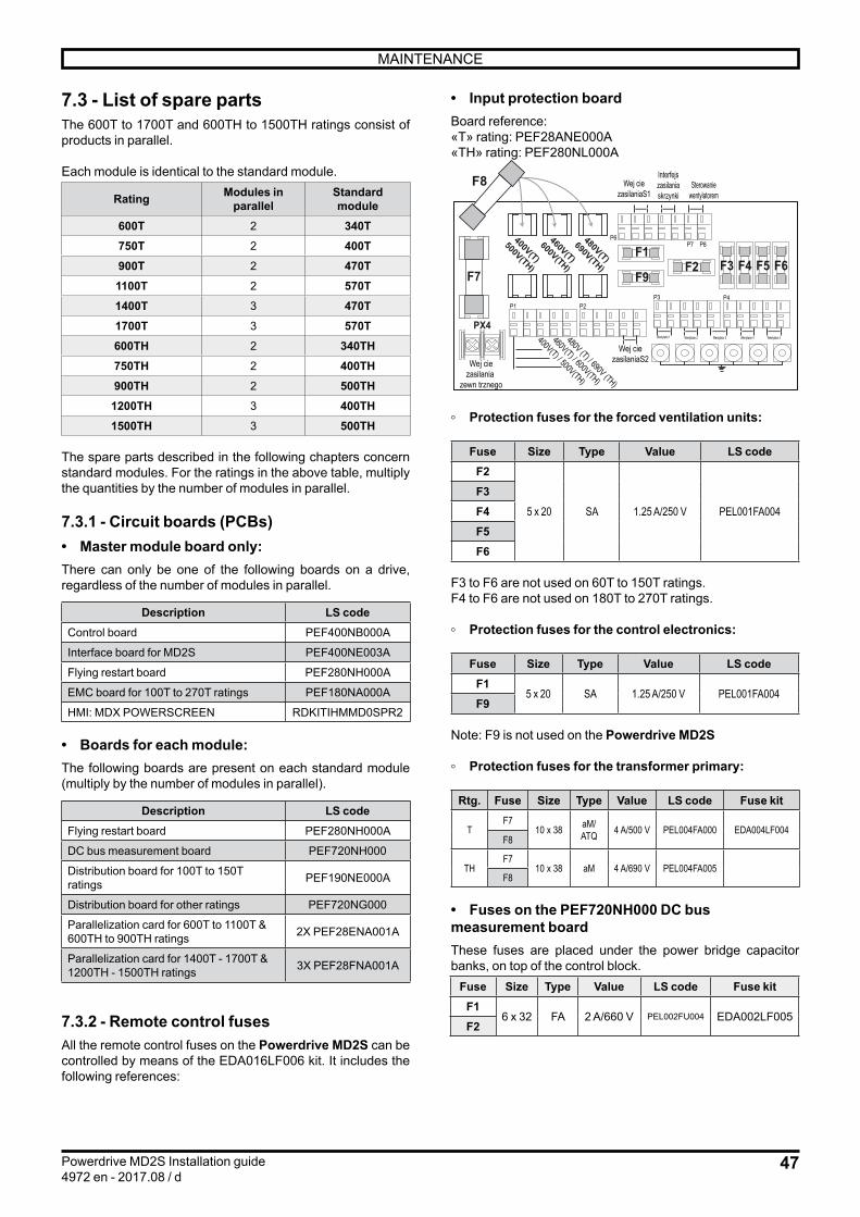
47
MAINTENANCE
Powerdrive MD2S Installation guide4972 en - 2017.08 / d
7.3 - List of spare partsThe 600T to 1700T and 600TH to 1500TH ratings consist of products in parallel.
Each module is identical to the standard module.
Rating Modules inparallel
Standard module
600T 2 340T750T 2 400T900T 2 470T1100T 2 570T1400T 3 470T1700T 3 570T600TH 2 340TH750TH 2 400TH900TH 2 500TH1200TH 3 400TH1500TH 3 500TH
The spare parts described in the following chapters concern standard modules. For the ratings in the above table, multiply the quantities by the number of modules in parallel.
7.3.1 - Circuit boards (PCBs)• Master module board only:There can only be one of the following boards on a drive, regardless of the number of modules in parallel.
Description LS codeControl board PEF400NB000A
Interface board for MD2S PEF400NE003A
Flying restart board PEF280NH000A
EMC board for 100T to 270T ratings PEF180NA000A
HMI: MDX POWERSCREEN RDKITIHMMD0SPR2
• Boards for each module:The following boards are present on each standard module (multiply by the number of modules in parallel).
Description LS codeFlying restart board PEF280NH000A
DC bus measurement board PEF720NH000
Distribution board for 100T to 150T ratings PEF190NE000A
Distribution board for other ratings PEF720NG000
Parallelization card for 600T to 1100T & 600TH to 900TH ratings 2X PEF28ENA001A
Parallelization card for 1400T - 1700T & 1200TH - 1500TH ratings 3X PEF28FNA001A
7.3.2 - Remote control fusesAll the remote control fuses on the Powerdrive MD2S can be controlled by means of the EDA016LF006 kit. It includes the following references:
• Input protection board Board reference: «T» rating: PEF28ANE000A«TH» rating: PEF280NL000A
F1F2 F3 F4 F5 F6
F9F7
PX4
460V(T)
600V(TH)
480V(T)
690V(TH)
400V(T)
500V(TH)
P1
F8
400V(T) / 500V(TH)
460V(T) / 600V(TH)
480V (T) / 690V (TH)
P2P3 P4
P6P7 P8
Interfejszasilaniaskrzynki
WejściezasilaniaS1
WejściezasilaniaS2Wejście
zasilania zewnętrznego
Sterowaniewentylatorem
Wentylator 1 Wentylator 2 Wentylator 3 Wentylator 4 Wentylator 5
◦ Protection fuses for the forced ventilation units:
Fuse Size Type Value LS codeF2
5 x 20 SA 1.25 A/250 V PEL001FA004F3F4F5F6
F3 to F6 are not used on 60T to 150T ratings.F4 to F6 are not used on 180T to 270T ratings.
◦ Protection fuses for the control electronics:
Fuse Size Type Value LS codeF1
5 x 20 SA 1.25 A/250 V PEL001FA004F9
Note: F9 is not used on the Powerdrive MD2S
◦ Protection fuses for the transformer primary:
Rtg. Fuse Size Type Value LS code Fuse kit
TF7
10 x 38 aM/ ATQ 4 A/500 V PEL004FA000 EDA004LF004
F8
THF7
10 x 38 aM 4 A/690 V PEL004FA005F8
• Fuses on the PEF720NH000 DC bus measurement boardThese fuses are placed under the power bridge capacitor banks, on top of the control block.
Fuse Size Type Value LS code Fuse kitF1
6 x 32 FA 2 A/660 V PEL002FU004 EDA002LF005F2

48
MAINTENANCE
Powerdrive MD2S Installation guide4972 en - 2017.08 / d
These fuses are placed on the incoming choke. Each phase is equipped with a fuse.
Rating Size Value LS code Kit of 3 fuses60T T30 200 A/660 V PEL200FU001 EDA200LF001
75T T31 250 A/660 V PEL250FU005 -
100T T31 315 A/660 V PEL315FU001 -
120T T31 350 A/660 V PEL350FU001 -
150T T31 450 A/660 V PEL450FU000 -
180T T31 500 A/660 V PEL500FU001 EDA500LF001
220T T33 630 A/690 V PEL630FU004 -
270T T33 800 A/690 V PEL800FU003 -
340T T33 1,000 A/660 V
PLE999FU000
400T T33 1,400 A/660 V
PLE999FU006470T T33
570T T33 1,600 A/660 V
PEL999FU005
270TH T31 450 A/660 V PEL450FU000
340TH T31 550A/690A PEL550FU003
400TH T33 700 A/660 V PEL700FU002
500TH T31 800A/690V PEL800FU003
7.3.4 - Power modules• Rectifier module
Rating Qty LS code60T - 75T 1 MPRB
100T - 120T 1 MPRC
150T 1 RDMPRD
180 T- 220T 1 MPRE
270T 1 RDMPRF
340T - 470T 1 LSRDG
570 1 LSRDH
270TH to 500TH 1 LSRDG 690V
600TH to 900TH 1 LSRDG 690V
1200TH to 1500TH 1 LSRDG 690V
• Inverter module
Rating Qty LS code60T 1 RDMPOA
75T 1 MPOC
100T 1 RDMPOD
120T 1 MPOE
150T 1 RDMPOF
180T 3 MPOG
220T 3 MPOH
270T 3 RDMPOI
340T 3 LSPPI
400T 3 LSPPJ
470T 3 LSPPN
570T 3 LSPPR
270TH 3 LSPPL 690V
340TH 3 LSPPM 690V
400TH to 500TH 3 LSPPN 690V
7.3.5 - Other parts
Description Qty LS code
100T to 150T fan 1BLOCVF3MDVIR
180T to 270T fan 2
340T to 570T fan4 BLOCVF340A400
340TH to 500TH fanRoof fan(100T to 570T & 340TH to 500TH)
1 BLOCVFTOIT
100T to 270T transformer 1 TRF750MA003
340T to 570T transformer 1 TRF115MA001
7.3.3 - High-speed power fuses

49
MAINTENANCE
Powerdrive MD2S Installation guide4972 en - 2017.08 / d
• 100T to 150T ratings
• 180T to 270T ratings
•
No. Name1 Rectifier module
2 Inverter module
3 Control block
4 Distribution board
5 Customization board
6 DC bus measurement board
7 Assembled ventilated frame
8 Forced ventilation unit
9 Forced ventilation in roof
10 AC choke
11 Fuse board
12 AC fuses
1
2
3 4 5
6
7
8
9
10
11
12
1
2
3 4 5
67
8
9
10
11
12
1
2
3 54
7
8
9
10
11
12
• 340T to 570T & 270 TH to 500T ratings

50
MAINTENANCE
Powerdrive MD2S Installation guide4972 en - 2017.08 / d

51
MAINTENANCE
Powerdrive MD2S Installation guide4972 en - 2017.08 / d

Moteurs Leroy-SomerHeadquarter: Boulevard Marcellin Leroy - CS 10015
16915 ANGOULÊME Cedex 9
Limited company with capital of 65,800,512 €RCS Angoulême 338 567 258
www.leroy-somer.com
IMP297NO612