PowerDesigner's ver - Web view02/11/2010 · Business process data – can be...
55
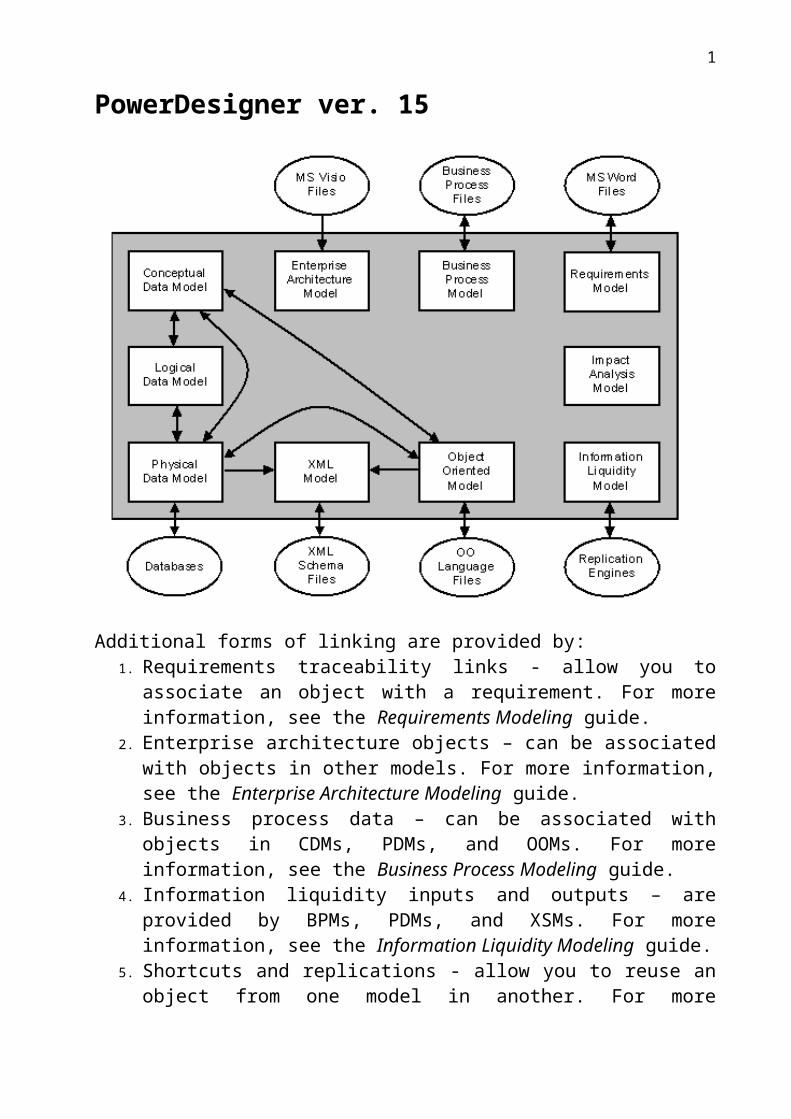
PowerDesigner ver. 15 Additional forms of linking are provided by: 1. Requirements traceability links - allow you to associate an object with a requirement. For more information, see the Requirements Modeling guide. 2. Enterprise architecture objects – can be associated with objects in other models. For more information, see the Enterprise Architecture Modeling guide. 3. Business process data – can be associated with objects in CDMs, PDMs, and OOMs. For more information, see the Business Process Modeling guide. 4. Information liquidity inputs and outputs – are provided by BPMs, PDMs, and XSMs. For more information, see the Information Liquidity Modeling guide. 5. Shortcuts and replications - allow you to reuse an object from one model in another. For more 1
Transcript of PowerDesigner's ver - Web view02/11/2010 · Business process data – can be...
PowerDesigner ver. 15
Additional forms of linking are provided by:1. Requirements traceability links - allow you to associate an object with a
requirement. For more information, see the Requirements Modeling guide.2. Enterprise architecture objects – can be associated with objects in other
models. For more information, see the Enterprise Architecture Modeling guide.
3. Business process data – can be associated with objects in CDMs, PDMs, and OOMs. For more information, see the Business Process Modeling guide.
4. Information liquidity inputs and outputs – are provided by BPMs, PDMs, and XSMs. For more information, see the Information Liquidity Modeling guide.
5. Shortcuts and replications - allow you to reuse an object from one model in another. For more information, see the Shortcuts and Object Replications chapter.
6. Extended links and extended dependencies - allow you to link any object in any model to another. For more information, see the Objects chapter.
PowerDesigner provides powerful tools to analyze the dependencies between model objects. For more information, see the Impact and Lineage Analysis chapter.
1
2

Conceptual Data Model Logical Data Model
Information Engineering (IE), Barker or IDEF 1/x notation
Physical Data Modelgenerate and reverse-engineer structures for over 60 RDBMS
DataWarehouse Modeling: Multidimensional Diagrams document the OLAP environment by representing cubes, facts,dimensions, dimensional hierarchies and queries
Data Mapping Editor
3

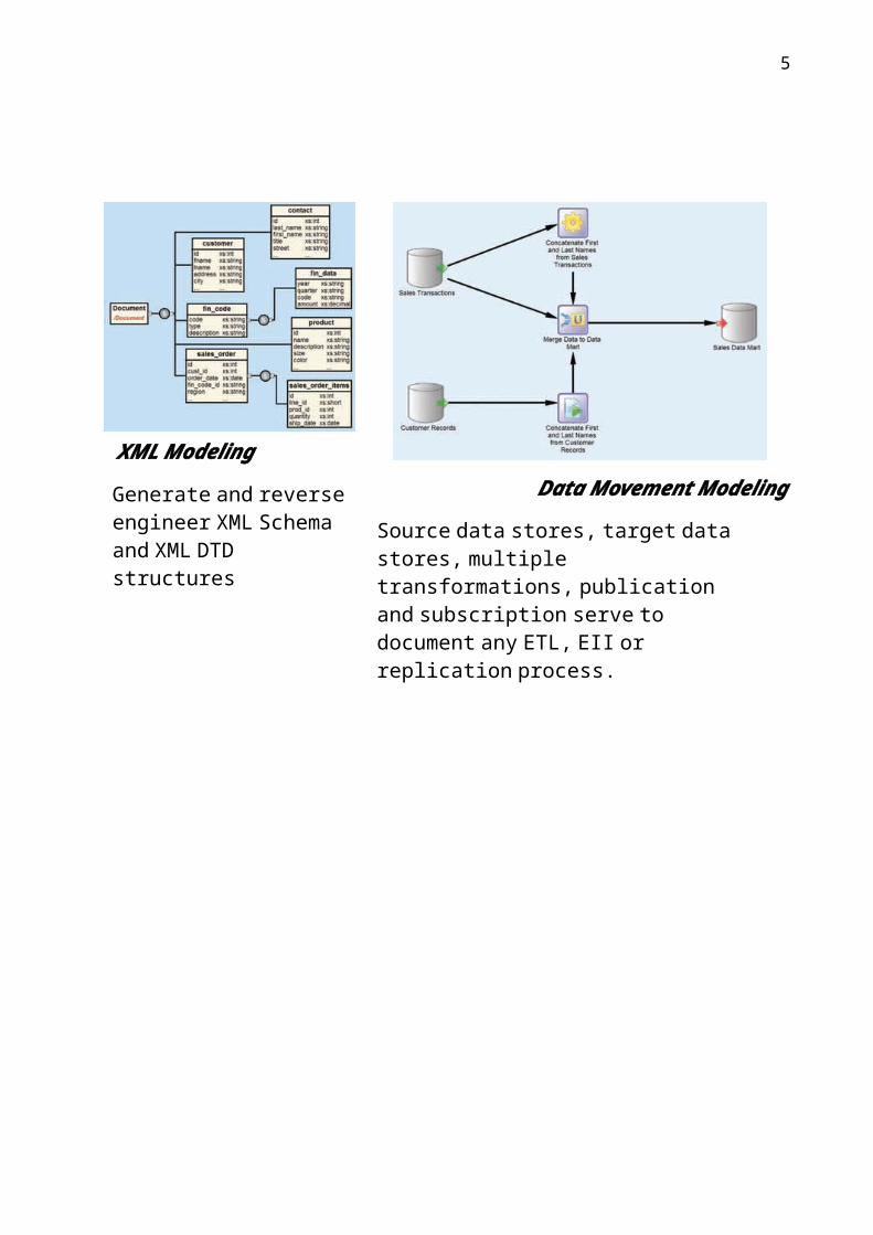
XML Modeling
Data Movement Modeling
Source data stores, target datastores, multiple transformations, publicationand subscription serve to document any ETL, EII or replication process.
Generate and reverse engineer XML Schema and XML DTD structures
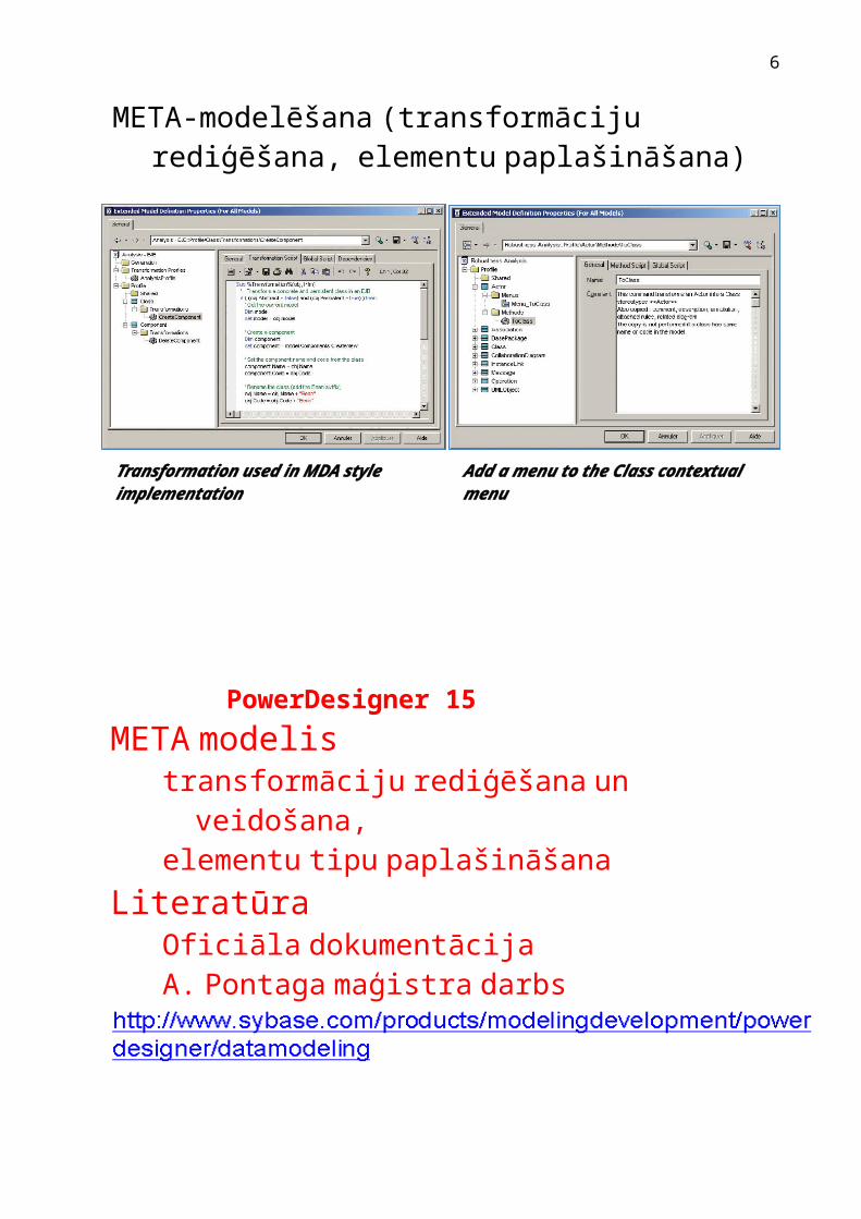
META-modelēšana (transformāciju rediģēšana, elementu paplašināšana)
Add a menu to the Class contextual menuTransformation used in MDA style implementation
4
PowerDesigner 15 META modelis
transformāciju rediģēšana un veidošana, elementu tipu paplašināšana
LiteratūraOficiāla dokumentācijaA. Pontaga maģistra darbs
5
Introduction to Model Object Mapping
Source Target Mapping type
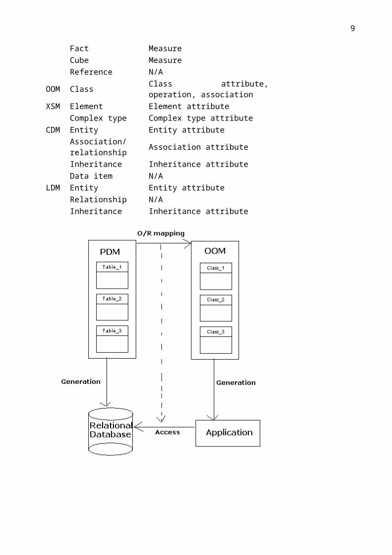
PDM OOM O/R (Object-Relational) – to associate classes to tables to store OOM objects into a relational database.
CDM OOM O/CDM (Object-Conceptual) – to associate classes and associations to CDM entities and associations or relationships.
OOM OOM O/O (Object-Object) – to associate classes and attributes from one OOM to another.
PDM PDM R/R (Relational-Relational) – to associate tables and views to other tables of another database. Multidimensional-Relational – to associate cubes, facts and dimensions to tables to populate OLAP cubes from relational databases.
PDM XSM XML/R (XML-Relational) – to associate elements and complex types to PDM tables, views and abstract data types.
OOM XSM XML/O (XML-Object) – to associate elements and complex types to OOM classes.
XSM XSM XML/XML (XML-XML) – to associate elements and complex types from one XML Model to another in order to define how an XML document can be transformed into another (usually, using XSLT or Xquery).
CDM CDM CDM/CDM (Conceptual-Conceptual) – to associate entities, associations, inheritances and data items from one CDM to another.
OOM CDM CDM/O (Conceptual-Object) – to associate entities and associations to OOM classes and associations to clarify object relationships.
LDM LDM LDM/LDM (Logical-Logical) to associate entities, relationships, and inheritances from one LDM to another.
Model Objects Sub-objects PDM Table Table column
View View column Dimension Attribute Fact Measure Cube Measure Reference N/A
OOM Class Class attribute, operation, association XSM Element Element attribute
Complex type Complex type attribute CDM Entity Entity attribute
Association/relationship Association attribute Inheritance Inheritance attribute Data item N/A
LDM Entity Entity attribute Relationship N/A Inheritance Inheritance attribute
6

7

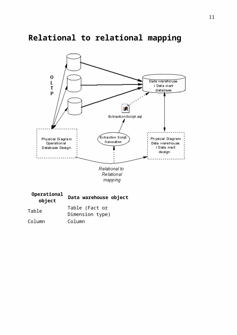
Relational to relational mapping
Operational object Data warehouse object Table Table (Fact or Dimension type) Column Column
8
Relational to multidimensional mapping
9

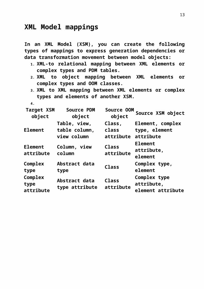
XML Model mappings
In an XML Model (XSM), you can create the following types of mappings to express generation dependencies or data transformation movement between model objects:
1. XML-to relational mapping between XML elements or complex types and PDM tables.
2. XML to object mapping between XML elements or complex types and OOM classes.
3. XML to XML mapping between XML elements or complex types and elements of another XSM.
4.
Target XSM object Source PDM object Source OOM
object Source XSM object
Element Table, view, table column, view column
Class, class attribute
Element, complex type, element attribute
Element attribute Column, view column Class
attribute Element attribute, element
Complex type Abstract data type Class Complex type, element Complex type attribute
Abstract data type attribute
Class attribute
Complex type attribute, element attribute
10
Conceptual Data Model mappings
In a Conceptual Data Model (CDM), you can create the following types of mappings to express a simple correspondence between model objects:
1. Conceptual to object mapping between CDM entities and OOM classes.2. Conceptual to conceptual mapping between CDM entities and the
entities of another CDM.
Target CDM object Source OOM object Source CDM object
Entity Class Entity, association, inheritance
Entity attribute Class attribute Entity attribute, association attribute, inheritance attribute
Association/relationship Association Entity, association, inheritance, relationship
Association attribute Association attribute
Association attribute, entity attribute, inheritance attribute
Inheritance Class Entity, association, inheritance
Inheritance attribute Class attribute Inheritance attribute, entity attribute, association attribute
Data item — Data item
11

Synchronizing an OOM with its Java Source
You can synchronize an Object Oriented Model (OOM) with its Java source
code, so that each time you modify the model, a source code file is
automatically created (for a new object) or updated (for an existing object).
Similarly, each time you modify a source code file and save the changes, they
appear in the diagram and the Model Explorer.
You can activate synchronization from the Model Explorer or Navigator. A
model is synchronized per package. The default package regroups all the
objects at the root of the model. Once a package has been synchronized with a
model, you cannot synchronize it with another model.
12
Conceptual diagram objects
13

14

15
16

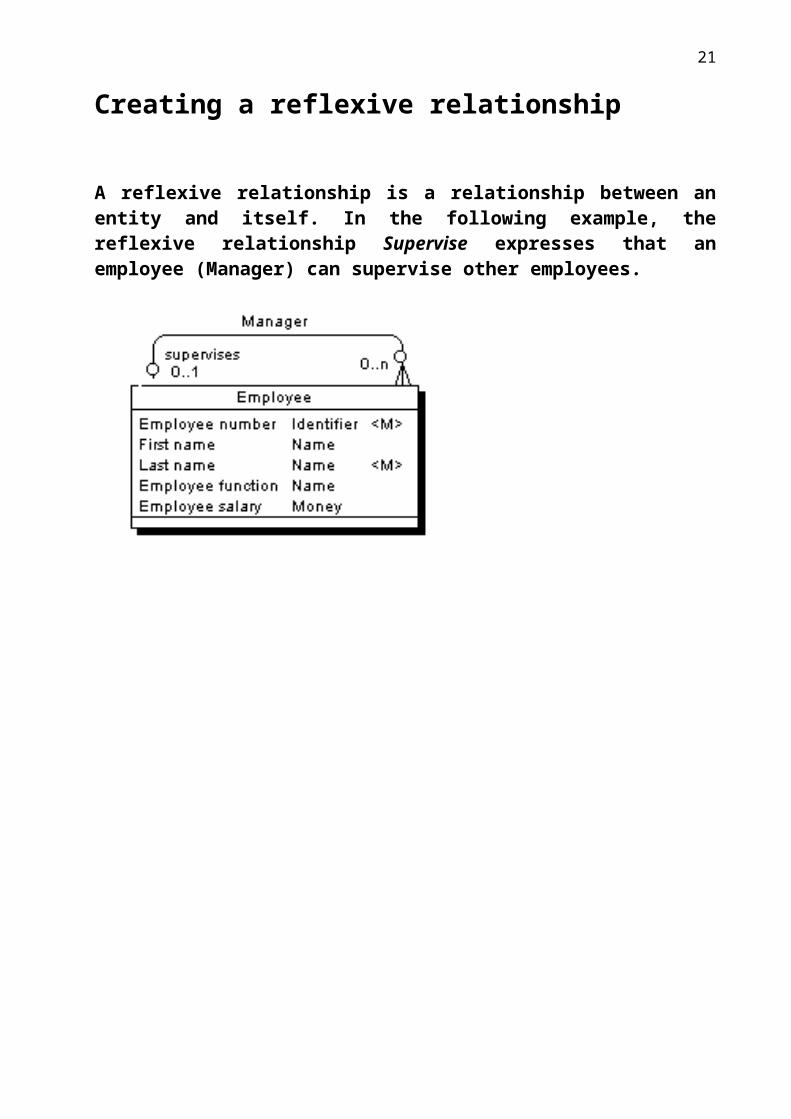
Creating a reflexive relationship
A reflexive relationship is a relationship between an entity and itself. In the following example, the reflexive relationship Supervise expresses that an employee (Manager) can supervise other employees.
17

18

19

Associations and Association Links (CDM)
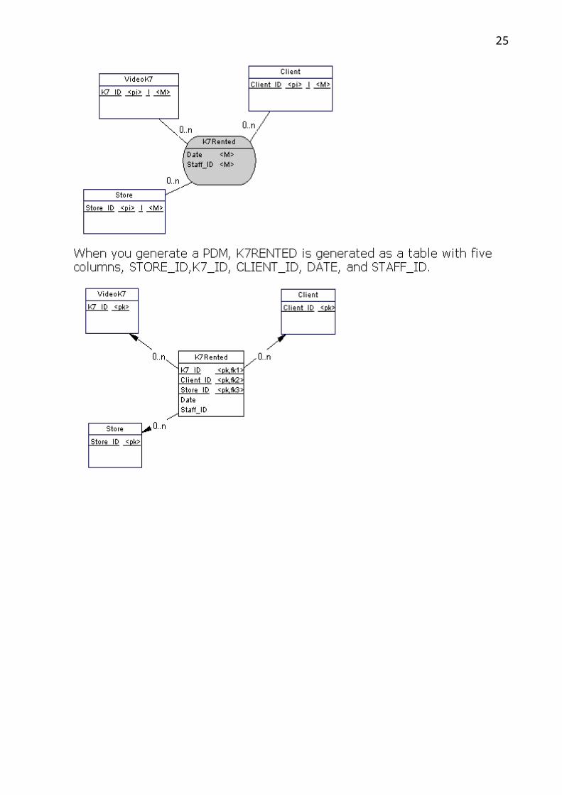
In the Merise modeling methodology an association is used to connect several entities that each represents clearly defined objects, but are linked by an event, which may not be so clearly represented by another entity. Each instance of an association corresponds to an instance of each entity linked to the association. When you generate a PDM from a CDM, associations are generated as tables or references.
20
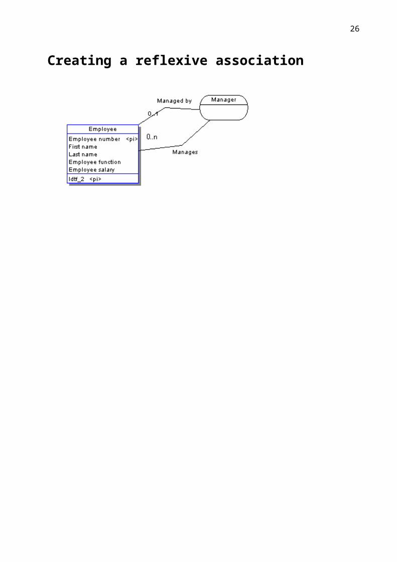
Creating a reflexive association
21

Defining a dependent association
In a dependent association, one entity is partially identified by another. Each entity must have an identifier. In some cases, however, the attributes of an entity are not sufficient to identify an occurrence of the entity. For these entities, their identifiers incorporate the identifier of another entity with which they have a dependent association.
22
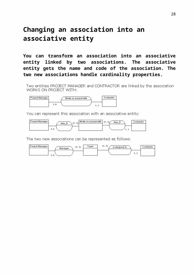
Changing an association into an associative entity
You can transform an association into an associative entity linked by two associations. The associative entity gets the name and code of the association. The two new associations handle cardinality properties.
23

Inheritances (CDM/LDM)
An inheritance allows you to define an entity as a special case of a more general entity. The general, or supertype (or parent) entity contains all of the common characteristics, and the subtype (or child) entity contains only the particular characteristics.In the example below, the Account entity represents all the bank accounts in the information system. There are two subtypes: checking accounts and savings accounts.There is no separate inheritance object in the Barker notation. You represent an inheritance by placing one entity symbol on top of another. Barker inheritances are always complete and mutually exclusive.
24
25
Logical diagram objects
26

Class diagram objects
27
Composite structure diagram objects
28

Object Diagram BasicsAn object diagram is a UML diagram that describes the structure of model elements and not their behavior or temporary information. The object diagram represents instances of classes (objects), instances of association (instance links), and dependencies. However, it does not represent inheritance relationships.As a diagram of instances, the object diagram shows an example of data structures with data values that corresponds to a detailed situation of the system at a particular point in time.The object diagram can be used for analysis purposes: constraints between classes that are not classically represented in a class diagram can typically be represented in an object diagram.If you are a novice in object modeling, instances usually have more meaning than classifiers do, because classifiers represent a level of abstraction. Gathering several instances under the same classifier helps you to understand what classifiers are. Moreover, even for analysts used to abstraction, the object diagram can help understand some structural constraints that cannot be easily graphically specified in a class diagram.In this respect, the object diagram is a limited use of a class diagram. For example, see the following figures representing a class and an object diagram: the class diagram specifies that a class Writer is linked to a class Document.The object diagram, deduced from this class diagram, highlights some of the following details: the object named John, instance of the class Writer is linked to two different objects Draft and Master that are both instances of the class Document.
29
Object diagram objects
30

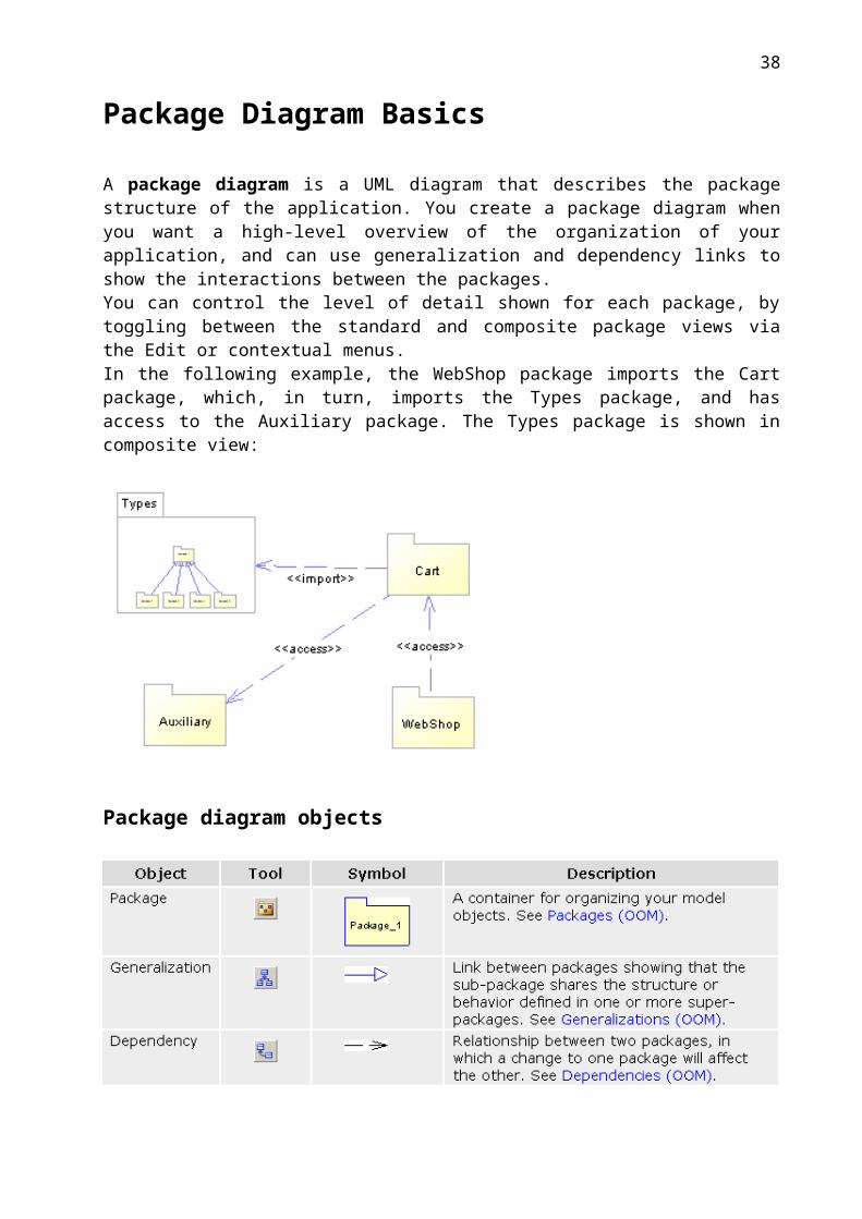
Package Diagram Basics
A package diagram is a UML diagram that describes the package structure of the application. You create a package diagram when you want a high-level overview of the organization of your application, and can use generalization and dependency links to show the interactions between the packages.You can control the level of detail shown for each package, by toggling between the standard and composite package views via the Edit or contextual menus. In the following example, the WebShop package imports the Cart package, which, in turn, imports the Types package, and has access to the Auxiliary package. The Types package is shown in composite view:
Package diagram objects
31

Associations (OOM)An association represents a structural relationship between classes or between a class and an interface.
32

33

34

35

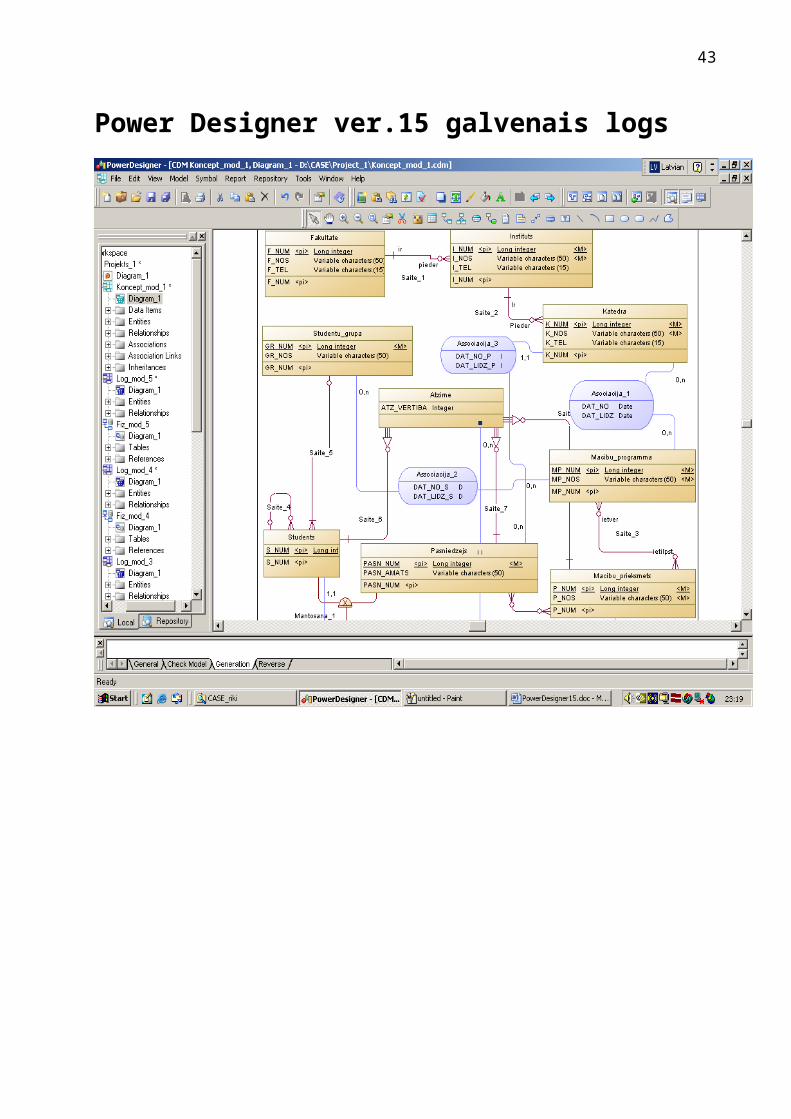
Power Designer ver.15 galvenais logs
36

37
38

39
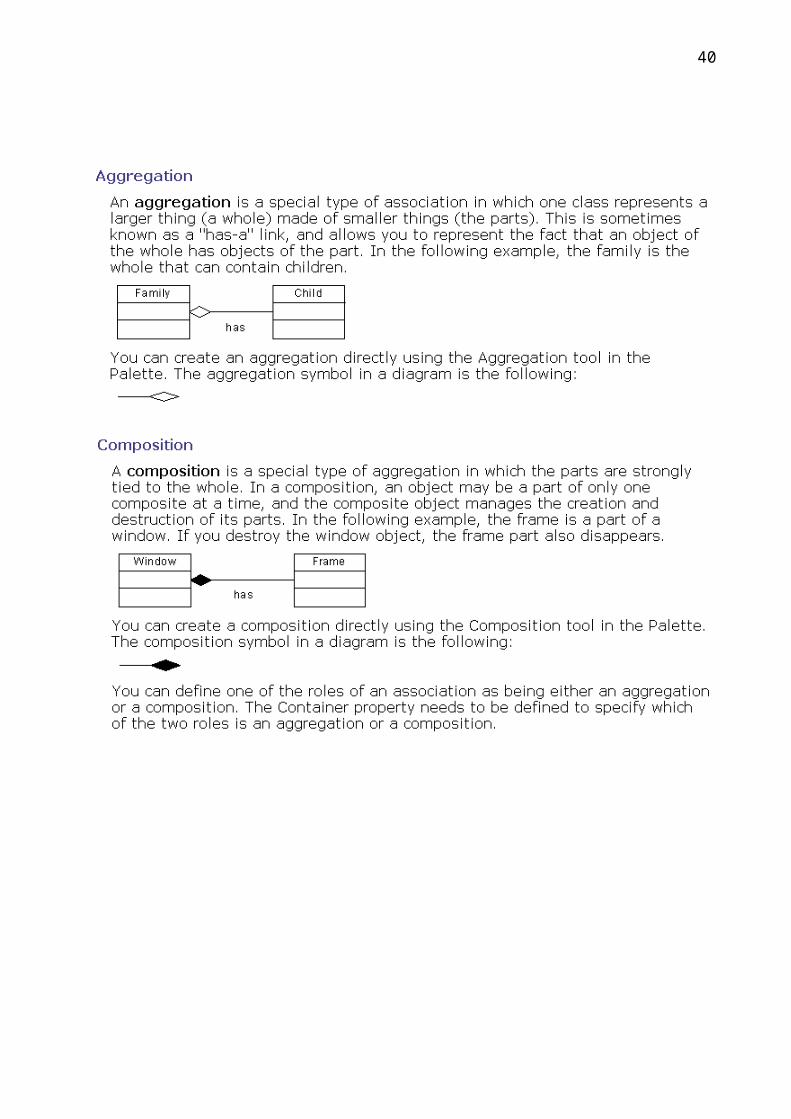
Mantošana
DB loģiskais modelis
DB fiziskais modelis (Oracle 10G)
40

„Vāja realitāte”
DB loģiskais modelis
DB fiziskais modelis
41

Asociācijas un saite „daudzi pret daudziem”
DB loģiskais modelis
DB fiziskais modelis
42
Asociācija ar ternāru saiti
DB loģiskais modelis
DB fiziskais modelis
43
Piemēra DB loģiskais modelis
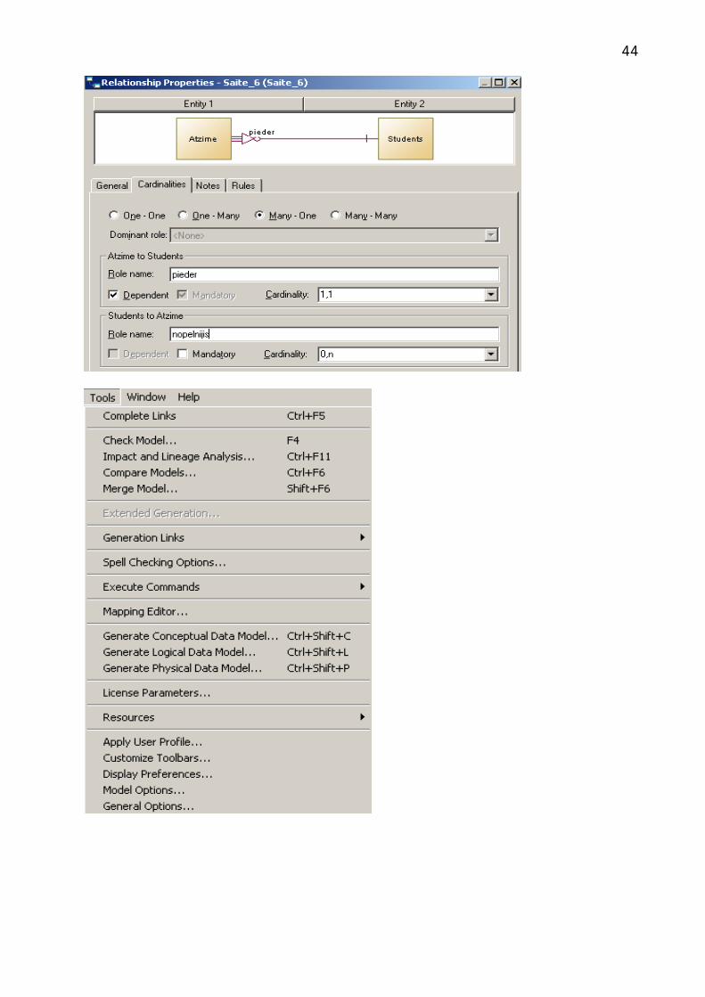
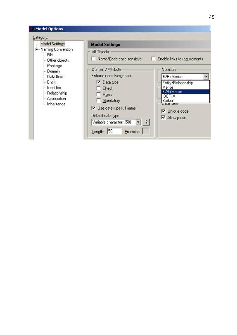
44
Associacija_3
Saite_1ir
pieder
Saite_2Ir
Pieder
Asociacija_1
Asociacija_1
Saite_3
Saite_3
Saite_5
Associacija_2
Associacija_2
Saite_6
Saite_7
Saite_8
Saite_9
Saite_9
Studenta_atz_saraksts
Studenta_atz_saraksts
Studenta_atz_saraksts
Fakultate#*o
F_NUMF_NOSF_TEL
Long integerVariable characters (50)Variable characters (15)
Instituts#*<fi>*o
I_NUMF_NUMI_NOSI_TEL
Long integerLong integerVariable characters (50)Variable characters (15)
Katedra#*<fi2>*<fi2>*<fi1>*ooo
K_NUMPERS_KODSPASN_NUMI_NUMK_NOSK_TELDAT_NO_PDAT_LIDZ_P
Long integerVariable characters (12)Long integerLong integerVariable characters (50)Variable characters (15)DateDate
Macibu_programma#*
MP_NUMMP_NOS
Long integerVariable characters (50)
Macibu_prieksmets#*
P_NUMP_NOS
Long integerVariable characters (50)
Asociacija_1*<fi1>*<fi2>oo
K_NUMMP_NUMDAT_NODAT_LIDZ
Long integerLong integerDateDate
Cilveks#**
PERS_KODSUZVARDSVARDS
Variable characters (12)Variable characters (50)Variable characters (50)
Saite_4
Saite_5
Saite_6
Studenta_atz_saraksts
Students#o<fi1>o<fi1>o<fi2>
S_NUMStu_PERS_KODSStu_S_NUMGR_NUM
Long integerVariable characters (12)Long integerLong integer
Associacija_3
Saite_7
Saite_9
Pasniedzejs#o
PASN_NUMPASN_AMATS
Long integerVariable characters (50)
Studentu_grupa#o
GR_NUMGR_NOS
Long integerVariable characters (50)
Associacija_2*<fi1>*<fi2>oo
GR_NUMMP_NUMDAT_NO_SDAT_LIDZ_S
Long integerLong integerDateDate
Atzime#####o
P_NUMPERS_KODSPASN_NUMStu_PERS_KODSS_NUMATZ_VERTIBA
Long integerVariable characters (12)Long integerVariable characters (12)Long integerInteger
Studenta_atz_saraksts*<fi1>*<fi2>*<fi2>*<fi2>*<fi2>*<fi2>*
P_NUMAtz_P_NUMPERS_KODSPASN_NUMStu_PERS_KODSS_NUMSAR_NUM
Long integerLong integerVariable characters (12)Long integerVariable characters (12)Long integerLong integer
Saite_3##
MP_NUMP_NUM
Long integerLong integer
Saite_9###
P_NUMPERS_KODSPASN_NUM
Long integerVariable characters (12)Long integer
Piemēra DB fiziskais modelis
45

piederir
Pieder
Ir
Fakultate
F_NUMF_NOSF_TEL
INTEGERVARCHAR2(50)VARCHAR2(15)
<pk>
Instituts
I_NUMF_NUMI_NOSI_TEL
INTEGERINTEGERVARCHAR2(50)VARCHAR2(15)
<pk><fk>
Katedra
K_NUMPERS_KODSPASN_NUMI_NUMK_NOSK_TELDAT_NO_PDAT_LIDZ_P
INTEGERVARCHAR2(12)INTEGERINTEGERVARCHAR2(50)VARCHAR2(15)DATEDATE
<pk><fk1><fk1><fk2>
Macibu_programma
MP_NUMMP_NOS
INTEGERVARCHAR2(50)
<pk>
Macibu_prieksmets
P_NUMP_NOS
INTEGERVARCHAR2(50)
<pk>
Asociacija_1
K_NUMMP_NUMDAT_NODAT_LIDZ
INTEGERINTEGERDATEDATE
<fk1><fk2>
Students
PERS_KODSS_NUMUZVARDSVARDSStu_PERS_KODSStu_S_NUMGR_NUM
VARCHAR2(12)INTEGERVARCHAR2(50)VARCHAR2(50)VARCHAR2(12)INTEGERINTEGER
<pk><pk>
<fk1><fk1><fk2>
Pasniedzejs
PERS_KODSPASN_NUMUZVARDSVARDSPASN_AMATS
VARCHAR2(12)INTEGERVARCHAR2(50)VARCHAR2(50)VARCHAR2(50)
<pk><pk>
Studentu_grupa
GR_NUMGR_NOS
INTEGERVARCHAR2(50)
<pk>
Associacija_2
GR_NUMMP_NUMDAT_NO_SDAT_LIDZ_S
INTEGERINTEGERDATEDATE
<fk1><fk2>
Atzime
P_NUMPERS_KODSPASN_NUMStu_PERS_KODSS_NUMATZ_VERTIBA
INTEGERVARCHAR2(12)INTEGERVARCHAR2(12)INTEGERINTEGER
<pk,fk3><pk,fk2><pk,fk2><pk,fk1><pk,fk1>
Studenta_atz_saraksts
Stu_S_NUMP_NUMAtz_P_NUMPERS_KODSPASN_NUMStu_PERS_KODSS_NUMSAR_NUM
INTEGERINTEGERINTEGERVARCHAR2(12)INTEGERVARCHAR2(12)INTEGERINTEGER
<fk1><fk2><fk3><fk3><fk3><fk3><fk3>
Saite_3
MP_NUMP_NUM
INTEGERINTEGER
<pk,fk2><pk,fk1>
Saite_9
P_NUMPERS_KODSPASN_NUM
INTEGERVARCHAR2(12)INTEGER
<pk,fk2><pk,fk1><pk,fk1>
"Arc" struktūra
46

Datu konceptuālais modelis
DB loģiskais modelis
47
Automašīna
Benzīna motors Dīzeļdzinējs
1
1 1
1
Automašīnas12345
Benzīna_motori124
Dīzeļdzinēji35
Virkne1
Virkne1.nextval
Virkne1.currentval