
PowerCyber: CPS Security Testbed for Power...
25
PowerCyber: CPS Security Testbed for Power Grid REMOTE ACCESS INTERFACE USER GUIDE Version 1.0 Funded jointly by: NSF Award #CNS 1446831 Compiled by: Sujatha K Swamy, Graduate Research Assistant Iowa State University Learn invent impact
Transcript of PowerCyber: CPS Security Testbed for Power...

PowerCyber: CPS Security Testbed for Power Grid
REMOTE ACCESS INTERFACE
USER GUIDE
Version 1.0
Funded jointly by:
NSF Award #CNS 1446831
Compiled by:
Sujatha K Swamy, Graduate Research Assistant
Iowa State University
Learn invent impact

TABLE OF CONTENTS
1. TESTBED OVERVIEW 1
1.1 Introduction 2
1.2 Architecture 2
1.3 Supported Use Cases 3
2. FRAMEWORK & DESIGN FLOW 4
2.1 Overall Framework 5
2.2 Design Flow 6
3. STORYBOARD SCENARIOS 9
4. USER MANUAL 13
5. CONTACT INFORMATION 23

2
1.1 Introduction
The PowerCyber testbed at Iowa State University, consists of a hybrid mix of industry standard hardware and
software, emulated components and real-time power system simulators for hardware-in-the-loop CPS security
experimentation for the Smart Grid. The PowerCyber test-bed provides a virtual critical infrastructure
environment wherein realistic experiments on wide area monitoring, wide area control and distributed
decision making in the smart grid environment can be carried out.
1.2 Architecture
Fig. 1. PowerCyber CPS Security Testbed Architecture
Figure 1 shows the current architecture of the PowerCyber CPS Security testbed at ISU. The testbed consists
of SCADA hardware/software from siemens that include substation automation system (SICAM PAS), control
center software (Power TG), SCADA and substation communication protocols (DNP3, IEC 61850, IEEE C37.118),
and security technologies (Scalance: Firewall, VPN), four multifunction protection relays (7SJ610, 7SJ82), three
SEL 421 Phasor Measurement Units (PMU) and a Phasor Data Concentrator (PDC).

3
1.3 Supported Use cases
1.3.1 Vulnerability Assessment:
PowerCyber supports vulnerability assessment of industry grade SCADA software and hardware platforms,
network protocols and configurations to detect unknown vulnerabilities based on standard vulnerability
databases. Several unknown vulnerabilities were discovered and a responsible disclosure process was
followed to disclose them to vendors and appropriate regulatory authorities.
1.3.2 Impact Analysis & Mitigation Research:
PowerCyber provides a realistic virtual critical infrastructure environment wherein realistic experiments on
wide-area monitoring, protection, and control in the smart grid environment can be carried out. Specifically,
the testbed has been used to evaluate coordinated attacks on Remedial Action Schemes, and data integrity
attacks on automatic generation control. Also, the testbed allows the implementation of defense measures
such as firewalls, intrusion detection systems, software patches, etc., to also evaluate the performance of
various mitigation strategies.
1.3.3 Testbed Federation:
Recently, the PowerCyber testbed was successfully federated with the DETER testbed and the ISERINK
platform, as part of Smart America Challenge and NIST Global City Teams Challenge to create a large-scale,
high-fidelity CPS security testbed environment. The federated testbed was used to demonstrate proof-of-
concept attack-defense experimentation on a wide-area protection scheme. Additional use cases to showcase
the utility of CPS testbed federation are currently being explored.
1.3.4 Attack-Defense Exercise & Operator Training:
The PowerCyber testbed and the ISERINK platform for cyber defense competitions had been recently
integrated to conduct realistic cyber attack-defense training exercises for utility practitioners at the NERC
GridSecCon 2015 conference. Also, PowerCyber has been used every year as part of an industry workshop to
provide hands-on training sessions.
1.3.5 Model Development:
PowerCyber testbed is currently developing a repository of standardized models and experimental datasets
for power systems and associated cyber systems to facilitate researchers in leveraging the testbed capabilities
for cyber security experimentation.
1.3.6 Remote Access:
In order to engage and enable a broad user community to perform a variety of power grid related cyber
security experimentation, a remote access framework is currently being developed on the PowerCyber
testbed. Specifically, this document will provide details of the implementation architecture, design flow and
user interface manual of the PowerCyber testbed remote access framework.

5
2.1 Overall Framework
Figure 2 shows the overall framework used for enabling remote CPS security experimentation on PowerCyber
testbed.The framework comprises of three fundamental building blocks.
Fig. 2. Remote Access Framework
2.1.1 Front-end Web Server - The front-end web server interacts with the user through a web-based user
interface. It provides options to select and customize experimental scenarios and also provides options
to collect experimental results.The front-end web server is integrated tightly to a backend
orchestration framework written in python.
2.1.2 Backend Orchestration Framework - The back-end framework orchestrates the creation/configuration
of the necessary cyber resources such as the SCADA virtual machines, manages the interaction with the
power system simulators and physical devices such as the relays and PMUs, coordinates various attack
actions and defense measures depending on the user input, and also provides a way for the users to
collect relevant simulation artifacts from the cyber system and the physical system in the form of log
files, packet captures, plots, etc.
2.1.3 Models and Libraries - In order to provide standard experimental scenarios as part of the remote
access web interface a library of commonly used power system models need to developed. This
includes models with appropriate WAMPAC applications modeled,commonly used attack vectors,
defense measures, etc.,

6
2.2 Design Flow
The following list represent key steps in the overall designflow for performing automated, cyber
attack/defense experimentation:
Real-Time Grid Simulation: The first stage involves the selection of the power system model to be used for
the experiment. For example, the standard IEEE system models such as 39 bus, 118 bus, etc.,
WAMPAC experiment selection: Once the powersystem model has been selected, the next stage is to
identify the Wide-Area Monitoring, Protection and Control (WAMPAC) experiment that is to be used for
the experiment. This stage would also involve an identification of how the physical components are
mapped to the power system model.
SCADA Configuration: This stage involves actions to appropriately spawn SCADA VM’s such as Control
Center, Substation VM’s depending on the WAMPAC experimental scenario chosen, and ensuring that the
appropriate network topology is setup between the various VM’s and the hardware devices that are
mapped as part of the scenario.
Attack Orchestration: Once all the systems are configured and initialized, the next stage is to spawn the
attacker VM’s and execute the attack vector on specified targets in coordination with the backend
orchestration framework.
Defense Instrumentation: After the power system and cyber system configuration steps are performed,
the next stage involves actions to spawn defense measures.The defense measures could be setup either in
the communication gateway nodes or on the individual hosts depending on the experimental scenarios
and user inputs.
Experimental Results: After the execution of the specified attack scenario, the next stage involves the
collection of experimental artifacts on the cyber layer such as log files, packet captures, network
performance metrics from the various systems and collection of power system simulation artifacts in the
form of datasets, or plots of system states such as voltages, power flow and frequency.
The following subsections describe in detail the various activities that are performed as part of the overall
design flow with respect to user interface (front-end) and experiment automation (backend).
2.2.1 User Interface Design
The user interface provides the user with an array of templates to select from and configure the system to
perform a specific type of cyber attack/ defense experiment. Figure 3 shows the various activities with respect
to the design flow for remote experimentation pertaining to the user interface. The user interface allows the
user to select the power system model that is to be used from a list of choices such as IEEE 39 bus model IEEE
118 bus model, etc., As part of Step 2, the user can select the WAMPAC experimental scenarios to be used. For
example, the list of available scenarios could be Remedial Action Schemes, Automatic Generation Control,
State Estimation, etc., Each one of these WAMPAC applications correspond to a specific scenario and based on
the user input they will be presented with subsequent web pages to select and map physical components such
as relays and PMUs appropriately into their experiment, and also it determines the type and number of SCADA
VM’s needed. For the cyber system configuration, the user interface provides user with options to select the

7
network topology in which SCADA components should be connected. As part of defense measures, the user
can select from either host based defense or network based defense.
Fig. 3. Design Flow for User Interface
Based on their inputs, user interface provides options to select from defense methodologies such as firewall,
intrusion detection and prevention based defense, etc., for implementation. For orchestrating the attack, the
user interface provides a list of attack vectors such as DOS attack, Command injection attack, coordinated
attack to choose from, along with options to choose the attack locations on the system selected. The user
interface has a visualization component where remote users can observe the status of the physical devices
that are part of the attack on the cyber layer, and also simultaneously observe the power system impacts on
the real-time power system simulator through real-time simulation plots. Once the experiment has been
performed, the user interface facilitates the collection of cyber system impacts such as downloading packet
captures, log files etc., during attack phase. As part of power system impacts, the user interface provides the
option of data collection relevant to power system parameters such as voltage and power flow plots.
2.2.2 Experiment Automation
Figure 4 lists the various activities as part of the design flow that relates to experiment automation. Each of
the activities is implemented using the backend orchestration framework through appropriate slave scripts
that communicate to a master script. With respect to the power system configuration, the automation tasks
involve loading, compilation of the appropriate power system model such as the IEEE 9 bus system model
simulator, initializing the runtime interface, and ensuring that the model has reached its steady state
operating condition before any attack actions are started. Depending on the WAMPAC experiment selection
made, the backend automation scripts would configure physical components accordingly so that they could be
mapped into the power system model for hardware-in-the-loop experiments, and also verify their integration

8
with the runtime interface. With respect to automating the cyber system, the backend configuration module
spawns control center and substation VM’s appropriately, and initializes the VM’s in a specific network
topology. Also, the scripts verify if inter-device communication is successful before proceeding further. Based
on user selection, the backend scripts implement and initialize network based or host based defense measures
such as firewalls, or intrusion detection systems on gateway nodes or on the hosts such as substation VM’s.
Fig. 4. Design Flow for Experiment Automation
As part of attack orchestration, the backend scripts would spawn attacker VM’s, which have a library of pre-
defined attack modules. Based on the experiment scenario, the master script coordinates and triggers the
specific attack scripts on these VM’s. Once the experiment has successfully begun, the backend scripts
periodically poll the status of the various devices involved in the experiment in the cyber layer, and update a
run-time visualization screen on the front-end web server. Simultaneously, the web-based interface can also
provide another screen with the run-time interface on the power system control VM to see the impact of the
attacks on the power system. Depending on the type of power system simulator selected and the type of
outputs requested by the user (i.e. real-time outputs vs. offline plots), the automation scripts would be
adapted to provide real-time outputs or data files that are collected for the experimental scenario accordingly.
As part of collecting the results on the cyber layer, the backend scripts would pull log files from the VM’s
where defense measures were deployed such as firewall and IDS logs, and packet captures from the gateway
node, besides other network performance statistics. Similarly, the scripts on the power system control node
would pull power system simulation artifacts such as data files or plots and make them available to the user as
experimental results.

10
This section provides storyboard scenario overview of template driven remote access to ISU PowerCyber
Testbed.
Story Board 1:
Cascading outage through a coordinated attack on power system protection scheme
In this scenario, the attack involves a combination of two coordinated attack actions on a power system
protection scheme known as Remedial Action Scheme (RAS). Typically, RAS are intended to take specific
protective measures to prevent the spread of large disturbances under heavy system loading conditions.
However, the attacker intelligently triggers the operation of this RAS by creating a data integrity attack on
unencrypted communication between the substation and the control center that uses the DNP3 protocol. In
order to create a cascading outage, the attacker also blocks the communication between the protection relays
that are involved in the RAS through a targeted Denial of Service (DoS) attack on one of the protection
controllers. This prevents the successful operation of the RAS and in turn initiates secondary protection to be
tripped to avoid thermal overload on the impacted transmission line. As a result of this coordinated attack
involving data integrity attack to trip a breaker and a DoS attack on RAS communications, the overall system
frequency is also affected as it causes the islanding of a generator from the rest of the system.
Story Board 2:
Manipulating AGC measurements/controls to affect system frequency
In this scenario, the attack involves a stealthy manipulation of measurements/controls used in Automatic
Generation Control (AGC) algorithm to destabilize and affect the frequency of the power grid. This attack is a
version of the classic Man-in-the-Middle attack, where the attacker intercepts the communication between
the control center and the remote substations and chooses to stealthily modify either the frequency or tie-line
measurements going to the control center, or the AGC control commands going to the generating stations.
This is achieved by executing an ARP poisoning attack first, which tricks the remote substation to forward the
data to the attacker before sending it to the external gateway. The attacker then selects the appropriate
information that is to be replaced and modifies it appropriately using custom attack scripts and forwards it to
the external gateway. As a result of this manipulation, there is a steady frequency deviation in the system.
Eventually, this frequency deviation causes the load in the system to be shed in an attempt to restore
frequency. A sustained attack could potentially lead to a major portion of the load in the power system to be
unserved.
Story Board 3:
Manipulating SCADA measurements to affect situational awareness in State Estimator
In this scenario, the attack involves a careful manipulation of the measurements (analog and status) that come
from the substation remote terminal units (RTU) to the control center for State Estimation. The attacker
performs a stealthy attack where he exploits his knowledge about the measurement configurations at multiple

11
substations to carefully select the locations where he would manipulate the measurements. The attack vector
involves the classic Man-in-the-Middle attack, where the attacker tricks the RTU to forward all its data to the
attacker’s machine instead of the substation gateway using an ARP poisoning attack. By decoding the
unencrypted network traffic, the attacker selects and modifies appropriately certain targeted measurements
to avoid detection by the State Estimator’s Bad Data Detectors. This does not cause any bad data alarms in the
control center and consequently, the attacker succeeds in impeding the situational awareness capabilities of
the operator. Consequently, all applications that rely on State Estimator would be affected such as
Contingency Analysis, Power Markets, etc., Also, this attack could be used to further trigger other attacks that
could cause additional damage such as opening/overloading critical transmission lines.
Story Board 4:
Using unencrypted RTU communication to send arbitrary commands to trip breakers
The attacker gains physical access to the process WAN, on which he is able to gain a network address. As the
data flows between RTUs and SCADA are not encrypted the attacker is able to read any transmitted data in
clear text. The attacker uses this opportunity to perform an ARP spoof attack and position himself between an
RTU and the PCU (i.e., a man-in-the-middle attack). As such, the attacker is able to both send malicious
requests to the RTU and hide to the operator the real events. The attacker uses this for an unauthorized
opening of a distribution feeder breaker feeding a major manufacturing industry connected directly on the 40
KV level. The attacker’s intention is to create a power outage that will severely disturb or stop the production
in a continuously operated plant in order to create economical and/or physical damage.
Story Board 5:
Denial of Service attack on RTU/protection devices communication to blind SCADA
The attacker has physical access to the RTU communication network and is as such able to connect his own
equipment to the network using a switch in an unmanned substation. From this point the attacker floods a
number of logical connections with a continuous stream of packets, which creates an overload in the Front-
End applications and blinds the operators to what is happening in the grid. The attacker has chosen a time for
the attack when a severe snow and ice storm is expected and the control operators are unable to counteract
the loss of physical devices created by the storm. This leads to an overload of power lines feeding the capital
city and this also goes unnoticed in the control centre. The blind SCADA severely delays the power restoration
efforts to reenergize the capital city.
Story Board 6:
Exploiting Social Engineering to gain access to Energy Management Systems/ Substation
Workstations
An uninformed operator in the control room connects his workstation to Internet during a night shift. He does
this to be able to use Facebook to chat with his friends and to surf on Internet. This operator has the tendency
to accept any friend request on Facebook and add as his friend. The attacker uses this to request the operator

12
to add him as a friend. In a chat, his Facebook friend sends him a link that was created by an attacker. Without
becoming suspicious, the operator clicks on the link and gives the attacker access to his control room
workstation. The attacker is now able to remotely connect to this system and he can open a shell with root
privileges on the compromised system. From his own location the attacker is now able to open SCADA displays
containing real-time information from the grid and to execute commands. He uses this to open HV breakers in
the power grid, which leads to cascading events that causes a total blackout of the high voltage grid.
Story Board 7:
Manipulating protection settings using Substation Automation tools
The attacker is an employee of the attacked utility and he has access to substations and to substation
engineering tools. He uses the engineering tools for the substation protection devices to set line protection
parameters to default values. The default values in the protection devices are defined at such low limits that
the protection devices will trip all power lines also at a normal operating state. The attack is done in a central
HV/MV substation on the MV side and it will cause a total blackout in the capital city.

14
Software Requirement: To access remote interface, user should connect to PowerCyber Virtual Private
Network(VPN) by downloading VPN clients such as OpenVPN, Viscosity or Tunnelblick.
NOTE: Please refer contact information section to obtain VPN certificates and credentials for access.
Connection URL : http://64.113.69.203:8080/DHSdemo/Welcome.php
1. Please provide credentials provided to log into the framework.
2. Upon succesfull login the interface provides story board scenarios to choose from.

15
3. The next webpage provides a video snippet overview of the story board scenario chosen.
4. Home page consists of with four major categories for experiment simulation.

16
5. The first step in real-time Grid simulation involves the selection of IEEE system model(such as 9-bus,
39-bus, etc.) and selection of Wide area monitoring and protection schemes (such as Remedial Action
Scheme, Automatic Generation Control, State Estimation, etc.).
6. The second step involves an identification of how the physical components should be mapped to the
power system model.
17
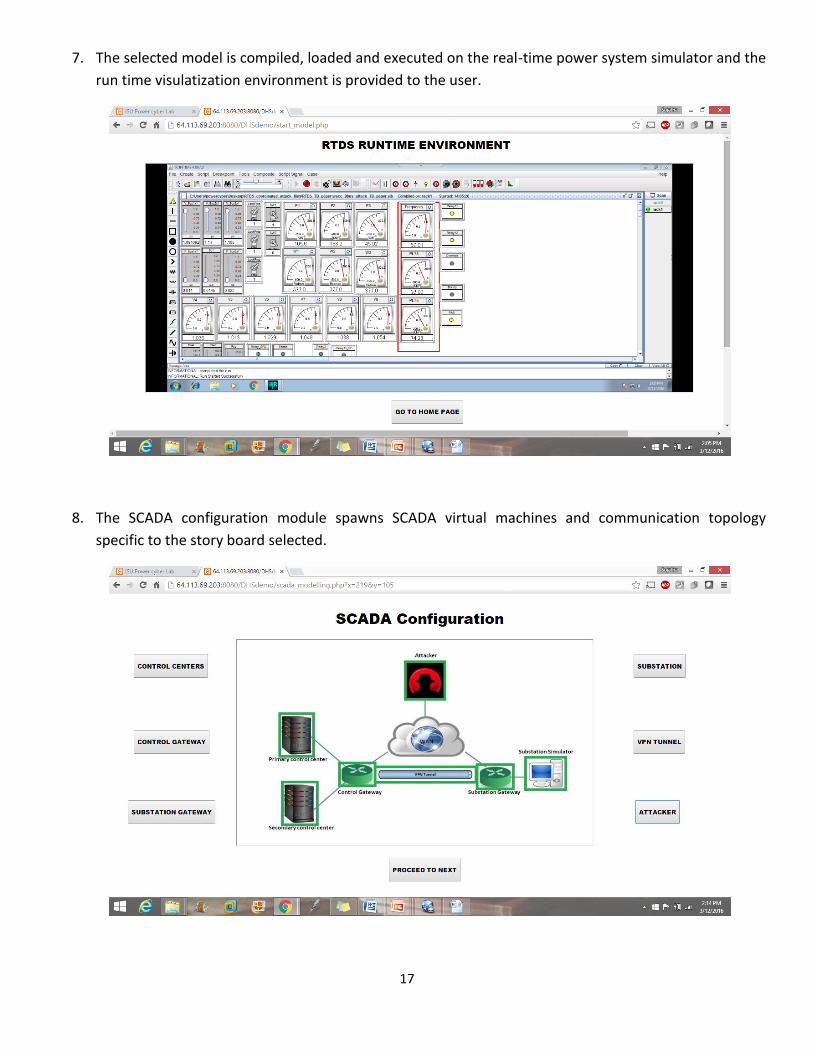
7. The selected model is compiled, loaded and executed on the real-time power system simulator and the
run time visulatization environment is provided to the user.
8. The SCADA configuration module spawns SCADA virtual machines and communication topology
specific to the story board selected.

18
9. The first step in attack orchestration involves recoinnaissance and enumeration. The user performs
host discovery to identify internet facing live hosts.
10. The Attacker tries to gather information by sniffing traffic between discovered hosts .
Due to the presence of site-to-site VPN tunnel between the control and substation network, information
gathering fails.

19
11. To gain access into the internal network, the attacker performs intense port scanning on targetted
hosts.
12. Vulnerability scanning identifies heartbleed vulnerability in substation gateway.

20
13. The second stage in attack orchestration involves vulnerability exploitation. The identified heart bleed
vulnerability is exploited to obtain login credentials.
14. The attacker obtains SSH access into the substation gateway which inturn provides access to the
substation internal network.

21
15. The attacker now executes the coordinated attack(Denial of service attack on RAS controller followed
by malicious breaker trip command injection attack) on the power system to create cascasing outage.
16. Defense instrumentation module provides options for firewall based defense, patch update, etc,.

22
17. SCADA network flow based firewall implementation blocks trip execution commands from hosts others
primary or secondary control centers.
18. Closing SSH on Wide area network interface prevents external user from obtaining shell access into the
substation gateway.
19. Updating the OpenSSL library in the substation gateway patches Heart Bleed bug preventing exploit of
this vulnerability.

23
CONTACT INFORMATION
PRINCIPAL INVESTIGATOR:
Dr. Manimaran Govindarasu
Mehl Professor & Associate Chair
Department of Electrical and Computer Engineering
2108 Coover Hall, Ames IA 50011, USA
Tel: (515) 294-9175 Fax: (515) 294-3637
Email: [email protected]
PROGRAM MANAGERS:
Dr. David Corman
NSF CPS Program
Email: [email protected]
Dr. Dan Massey
DHS S&T Cyber Security Division
Email: [email protected]
WEBSITE:
http://powercyber.ece.iastate.edu/
Learn invent impact