PowerConnect W-Series 802.11n Networks - Dell · 2 | Chapter 1: Reference Architecture Dell...
78
PowerConnect W-Series 802.11n Networks )..... Validated Reference Design Version 8
Transcript of PowerConnect W-Series 802.11n Networks - Dell · 2 | Chapter 1: Reference Architecture Dell...

PowerConnect W-Series802.11n Networks
)..... Validated Reference Design Version 8
Copyright
This document is for informational purposes only and may contain typographical errors and technical inaccuracies. The content is provided as is, without express or implied warranties of any kind.
© 2012 Dell Inc. All rights reserved. Dell and its affiliates cannot be responsible for errors or omissions in typography or photography. Dell™, the DELL™ logo, PowerConnect™ and PowerConnect-W are trademarks of Dell Inc. Microsoft, Windows, and Windows Server are either trademarks or registered trademarks of Microsoft Corporation in the United States and/or other countries. Other trademarks and trade names may be used in this document to refer to either the entities claiming the marks and names or their products. Dell disclaims proprietary interest in the marks and names of others.
© 2012 Aruba Networks, Inc. Aruba Networks trademarks include Airwave, Aruba Networks®, Aruba Wireless Networks®, the registered Aruba the Mobile Edge Company logo, and Aruba Mobility Management System®.
All rights reserved. Specifications in this manual are subject to change without notice.
Originated in the USA. All other trademarks are the property of their respective owners.
Open Source Code
Certain Aruba products include Open Source software code developed by third parties, including software code subject to the GNU General Public License (GPL), GNU Lesser General Public License (LGPL), or other Open Source Licenses. The Open Source code used can be found at this site:http://www.arubanetworks.com/open_source
Legal Notice
The use of Aruba Networks, Inc. switching platforms and software, by all individuals or corporations, to terminate other vendors’ VPN client devices constitutes complete acceptance of liability by that individual or corporation for this action and indemnifies, in full, Aruba Networks, Inc. from any and all legal actions that might be taken against it with respect to infringement of copyright on behalf of those vendors.
Dell PowerConnect W-Series: 802.11n Networks April 2012
Contents
Chapter 1: Reference Architecture.............................................................................. 1Chapter 2: Summary of Recommendations ................................................................ 3Chapter 3: Introduction to 802.11n ............................................................................. 7Chapter 4: Adaptive Radio Management.................................................................. 17Chapter 5: Wi-Fi Security and Spectrum Visibility with RFProtect......................... 37Chapter 6: Wi-Fi Multimedia and Quality of Service............................................... 49Chapter 7: Understanding Wireless Authentication and Encryption ........................ 55Chapter 8: Understanding Configuration Profiles, AP Groups, and Virtual APs ..... 63Chapter 9: Dell PowerConnect W-Series APs .......................................................... 69Chapter 10: Conclusion............................................................................................. 75
Dell PowerConnect W-Series: 802.11n Networks
Chapter 1: Reference Architecture
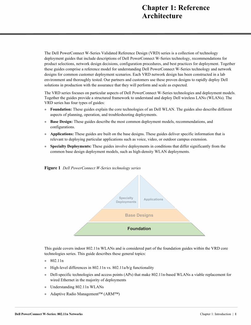
The Dell PowerConnect W-Series Validated Reference Design (VRD) series is a collection of technology deployment guides that include descriptions of Dell PowerConnect W-Series technology, recommendations for product selections, network design decisions, configuration procedures, and best practices for deployment. Together these guides comprise a reference model for understanding Dell PowerConnect W-Series technology and network designs for common customer deployment scenarios. Each VRD network design has been constructed in a lab environment and thoroughly tested. Our partners and customers use these proven designs to rapidly deploy Dell solutions in production with the assurance that they will perform and scale as expected.
The VRD series focuses on particular aspects of Dell PowerConnect W-Series technologies and deployment models. Together the guides provide a structured framework to understand and deploy Dell wireless LANs (WLANs). The VRD series has four types of guides:
Foundation: These guides explain the core technologies of an Dell WLAN. The guides also describe different aspects of planning, operation, and troubleshooting deployments.
Base Design: These guides describe the most common deployment models, recommendations, and configurations.
Applications: These guides are built on the base designs. These guides deliver specific information that is relevant to deploying particular applications such as voice, video, or outdoor campus extension.
Specialty Deployments: These guides involve deployments in conditions that differ significantly from the common base design deployment models, such as high-density WLAN deployments.
Figure 1 Dell PowerConnect W-Series technology series
This guide covers indoor 802.11n WLANs and is considered part of the foundation guides within the VRD core technologies series. This guide describes these general topics:
802.11n
High-level differences in 802.11n vs. 802.11a/b/g functionality
Dell-specific technologies and access points (APs) that make 802.11n-based WLANs a viable replacement for wired Ethernet in the majority of deployments
Understanding 802.11n WLANs
Adaptive Radio Management™ (ARM™)
Foundation
Base Designs
SpecialtyDeployments
Applications
Chapter 1: Introduction | 1
Spectrum analysis
RFProtect®
QoS and WMM
Understanding wireless encryption and authentication
Understanding virtual APs
Indoor APs and antenna options
Table 1 lists the current software versions for this guide
This guide is a foundation-level guide, and therefore it will not cover the configuration of the Dell PowerConnect W-Series system. Instead, this guide provides the baseline knowledge that a wireless engineer must use to deploy an architecture that is based on the dependent AP model.
Dell PowerConnect W-Series technical documentation is available for download from the Dell support site http://support.dell.com/manuals. These documents present detailed feature and functionality explanations outside the scope of the VRD series.
Support for the Dell PowerConnect W-Series can be found at http:/www.dell.com/wireless and http/www.dell.com/us/enterprise/p/powerconnect-w and clicking on Support.
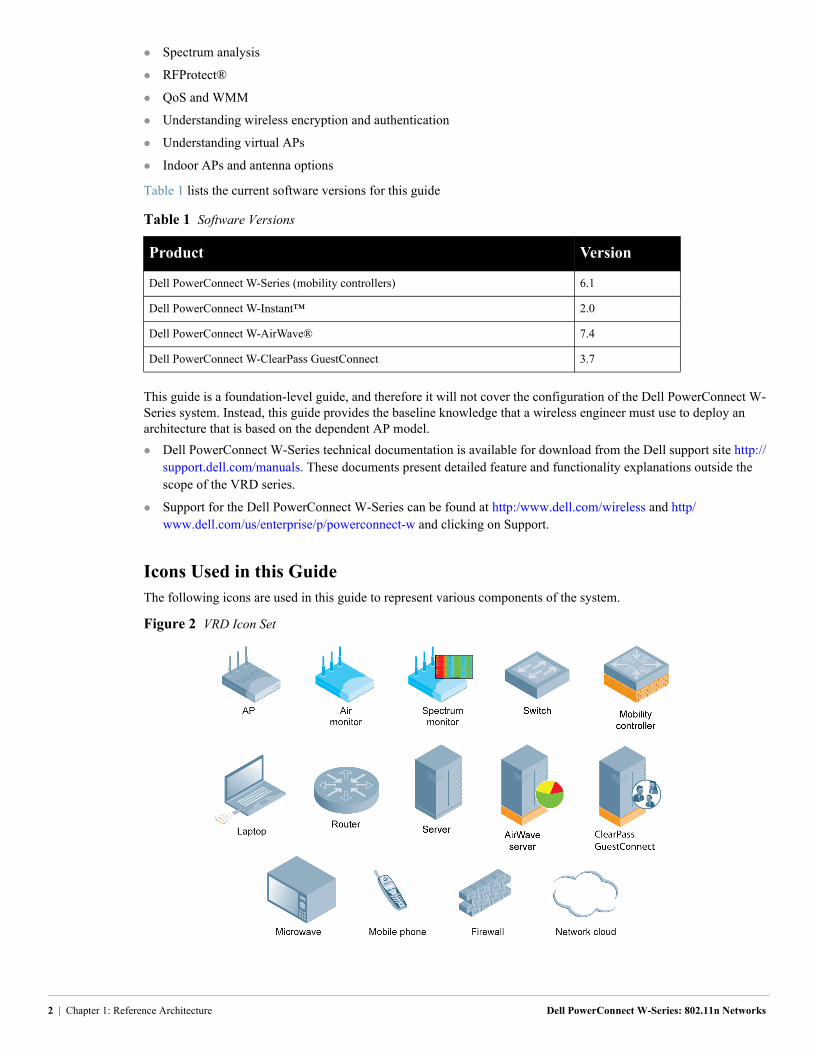
Icons Used in this GuideThe following icons are used in this guide to represent various components of the system.
Figure 2 VRD Icon Set
Table 1 Software Versions
Product Version
Dell PowerConnect W-Series (mobility controllers) 6.1
Dell PowerConnect W-Instant™ 2.0
Dell PowerConnect W-AirWave® 7.4
Dell PowerConnect W-ClearPass GuestConnect 3.7
2 | Chapter 1: Reference Architecture Dell PowerConnect W-Series: 802.11n Networks
Dell PowerConnect W-Series: 802.11n Networks
Chapter 2: Summary of Recommendations
The following tables summarize the recommendations made in this guide. These summaries are not a replacement for the material, but rather a quick reference to be referred back to at a later date.
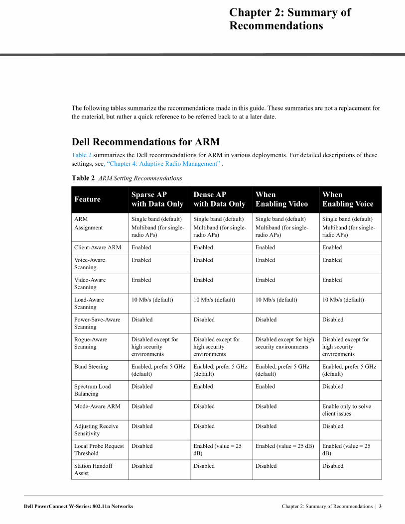
Dell Recommendations for ARMTable 2 summarizes the Dell recommendations for ARM in various deployments. For detailed descriptions of these settings, see, “Chapter 4: Adaptive Radio Management” .
Table 2 ARM Setting Recommendations
FeatureSparse AP with Data Only
Dense AP with Data Only
When Enabling Video
When Enabling Voice
ARM
Assignment
Single band (default)
Multiband (for single-radio APs)
Single band (default)
Multiband (for single-radio APs)
Single band (default)
Multiband (for single-radio APs)
Single band (default)
Multiband (for single-radio APs)
Client-Aware ARM Enabled Enabled Enabled Enabled
Voice-Aware Scanning
Enabled Enabled Enabled Enabled
Video-Aware Scanning
Enabled Enabled Enabled Enabled
Load-Aware Scanning
10 Mb/s (default) 10 Mb/s (default) 10 Mb/s (default) 10 Mb/s (default)
Power-Save-Aware Scanning
Disabled Disabled Disabled Disabled
Rogue-Aware Scanning
Disabled except for high security environments
Disabled except for high security environments
Disabled except for high security environments
Disabled except for high security environments
Band Steering Enabled, prefer 5 GHz (default)
Enabled, prefer 5 GHz (default)
Enabled, prefer 5 GHz (default)
Enabled, prefer 5 GHz (default)
Spectrum Load Balancing
Disabled Enabled Enabled Disabled
Mode-Aware ARM Disabled Disabled Disabled Enable only to solve client issues
Adjusting Receive Sensitivity
Disabled Disabled Disabled Disabled
Local Probe Request Threshold
Disabled Enabled (value = 25 dB)
Enabled (value = 25 dB) Enabled (value = 25 dB)
Station Handoff Assist
Disabled Disabled Disabled Disabled
Chapter 2: Summary of Recommendations | 3
RFProtect RecommendationsRFProtect is a licensed software module that enables additional security and troubleshooting functionality on APs and the mobility controller. Dell recommends RFProtect for any organization that needs wireless IDS/IPS functionality. Organizations that are concerned about attacks and those subject to compliance reporting will benefit from the features that RFProtect provides. Examples of organizations that must report compliance are retailers under the payment card industry (PCI), and the healthcare industry for the health insurance portability and accountability act (HIPAA).
All organizations benefit from spectrum analysis when they troubleshoot wireless interference issues. Using RFProtect, the Dell PowerConnect W-Series 802.11n APs can be put in to spectrum monitor mode for advanced troubleshooting. This capability provides an AP-level view of the interference and eliminates the need for a visit to the location for troubleshooting.
For most installations, the default RFProtect settings provide the appropriate level of alerts for most organizations. Dell recommends working with experienced RF security engineers and a legal advisor familiar with local laws to select the correct settings to meet the needs of the organization.
For detailed descriptions of these settings, see , “Chapter 5: Wi-Fi Security and Spectrum Visibility with RFProtect” on page 37.
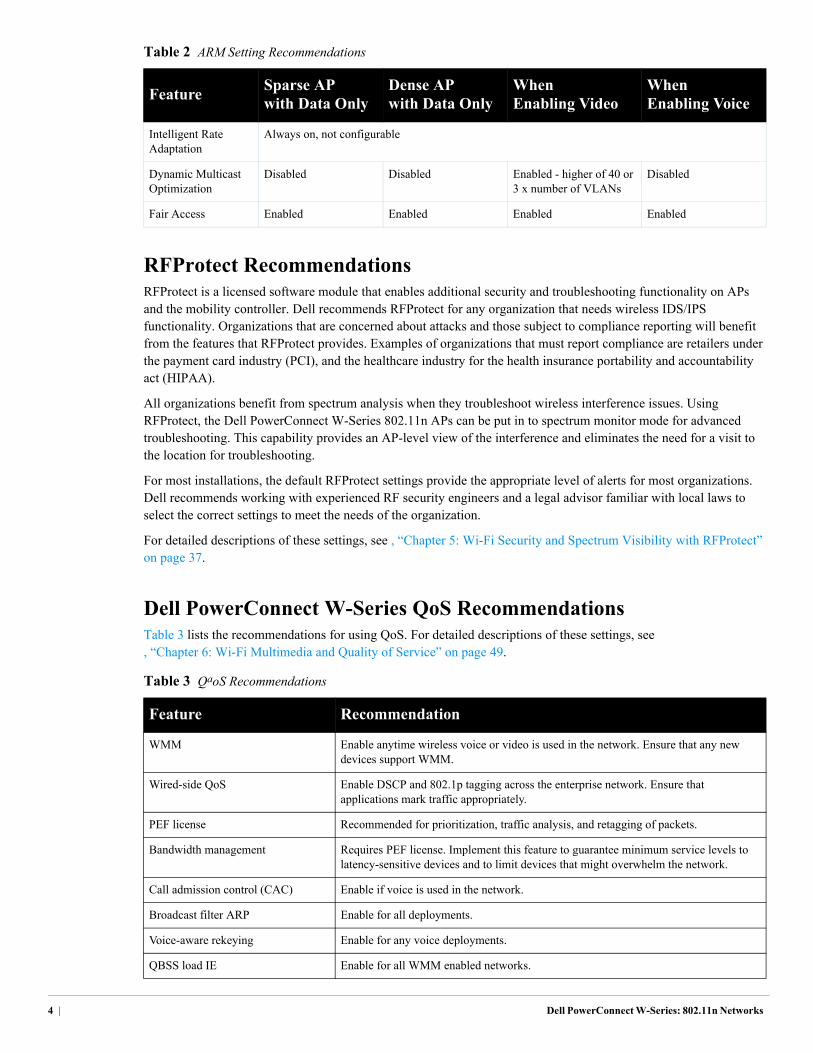
Dell PowerConnect W-Series QoS RecommendationsTable 3 lists the recommendations for using QoS. For detailed descriptions of these settings, see , “Chapter 6: Wi-Fi Multimedia and Quality of Service” on page 49.
Intelligent Rate Adaptation
Always on, not configurable
Dynamic Multicast Optimization
Disabled Disabled Enabled - higher of 40 or 3 x number of VLANs
Disabled
Fair Access Enabled Enabled Enabled Enabled
Table 3 QaoS Recommendations
Feature Recommendation
WMM Enable anytime wireless voice or video is used in the network. Ensure that any new devices support WMM.
Wired-side QoS Enable DSCP and 802.1p tagging across the enterprise network. Ensure that applications mark traffic appropriately.
PEF license Recommended for prioritization, traffic analysis, and retagging of packets.
Bandwidth management Requires PEF license. Implement this feature to guarantee minimum service levels to latency-sensitive devices and to limit devices that might overwhelm the network.
Call admission control (CAC) Enable if voice is used in the network.
Broadcast filter ARP Enable for all deployments.
Voice-aware rekeying Enable for any voice deployments.
QBSS load IE Enable for all WMM enabled networks.
Table 2 ARM Setting Recommendations
FeatureSparse AP with Data Only
Dense AP with Data Only
When Enabling Video
When Enabling Voice
4 | Dell PowerConnect W-Series: 802.11n Networks
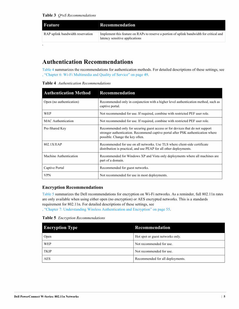
Authentication RecommendationsTable 4 summarizes the recommendations for authentication methods. For detailed descriptions of these settings, see , “Chapter 6: Wi-Fi Multimedia and Quality of Service” on page 49.
Encryption Recommendations
Table 5 summarizes the Dell recommendations for encryption on Wi-Fi networks. As a reminder, full 802.11n rates are only available when using either open (no encryption) or AES encrypted networks. This is a standards requirement for 802.11n. For detailed descriptions of these settings, see , “Chapter 7: Understanding Wireless Authentication and Encryption” on page 55.
RAP uplink bandwidth reservation Implement this feature on RAPs to reserve a portion of uplink bandwidth for critical and latency sensitive applications
a.
Table 4 Authentication Recommendations
Authentication Method Recommendation
Open (no authentication) Recommended only in conjunction with a higher level authentication method, such as captive portal.
WEP Not recommended for use. If required, combine with restricted PEF user role.
MAC Authentication Not recommended for use. If required, combine with restricted PEF user role.
Pre-Shared Key Recommended only for securing guest access or for devices that do not support stronger authentication. Recommend captive portal after PSK authentication where possible. Change the key often.
802.1X/EAP Recommended for use on all networks. Use TLS where client-side certificate distribution is practical, and use PEAP for all other deployments.
Machine Authentication Recommended for Windows XP and Vista only deployments where all machines are part of a domain.
Captive Portal Recommended for guest networks.
VPN Not recommended for use in most deployments.
Table 5 Encryption Recommendations
Encryption Type Recommendation
Open Hot spot or guest networks only.
WEP Not recommended for use.
TKIP Not recommended for use.
AES Recommended for all deployments.
Table 3 QaoS Recommendations
Feature Recommendation
Dell PowerConnect W-Series: 802.11n Networks | 5
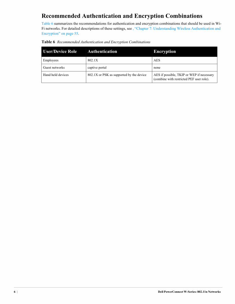
Recommended Authentication and Encryption CombinationsTable 6 summarizes the recommendations for authentication and encryption combinations that should be used in Wi-Fi networks. For detailed descriptions of these settings, see , “Chapter 7: Understanding Wireless Authentication and Encryption” on page 55.
Table 6 Recommended Authentication and Encryption Combinations
User/Device Role Authentication Encryption
Employees 802.1X AES
Guest networks captive portal none
Hand held devices 802.1X or PSK as supported by the device AES if possible, TKIP or WEP if necessary (combine with restricted PEF user role).
6 | Dell PowerConnect W-Series: 802.11n Networks
Dell PowerConnect W-Series: 802.11n Networks
Chapter 3: Introduction to 802.11n
802.11n Features and Benefits802.11n is the latest amendment to the 802.11 standard and it increases client speed and reliability to provide a wire-like service. This new level of performance has enabled a shift from wireless as a convenience network to wireless as the primary network connection in many organizations. These organizations are also pushed to adopt wireless as usage increases for dual-mode smart phones and for 802.11-only devices, such as tablet computers that have no Ethernet connections.
Ratification and Compatibility
The IEEE ratified the 802.11n amendment in September of 2009, but by that time 802.11n APs and clients based on an early draft of the 802.11n standard were already actively deployed. In many organizations, deployment was driven when the Wi-Fi Alliance® used an early draft of the amendment and certified “draft-n” products as interoperable. Interoperability certification gave customers the confidence to deploy the products. This certification also gave the vendors the ability to start actively producing and deploying 802.11n capable devices.
The devices produced under the pre-n certification are still in production today and all Dell APs meet the final standard. Backward compatibility between 802.11n APs and legacy clients is a key part of the amendment. Backward compatibility means that stations that previously connected to 802.11a, b, or g APs are still capable of connecting to 802.11n APs. New networks are now being deployed with 802.11n APs even where the clients do not support the standard.
Higher-Speed Networks
The promise of 802.11n networks is to provide “wire-like” speeds to the end user, eventually as much as 600 Mb/s per radio. This speed is achievable by using multiple technologies, including the use of multiple-input and multiple-output (MIMO) technology. MIMO technology combines multiple send and receive antennas, and multiple streams of data being sent at the same time. In addition, the 802.11n specification adds new encoding algorithms and wider channels. This all comes together to increase the data transfer rate significantly.
Understanding MIMO
Unlike traditional 802.11a/b/g radios, which use single-input and single-output (SISO), 802.11n radios use MIMO technology to increase throughput by increasing the number of radio transmit and receive chains. An AP or client may have up to four transmit and four receive chains, and it is possible to have a different number of transmit vs. receive chains. Figure 3 shows the difference between a SISO and MIMO transmission.
Chapter 3: Introduction to 802.11n | 7
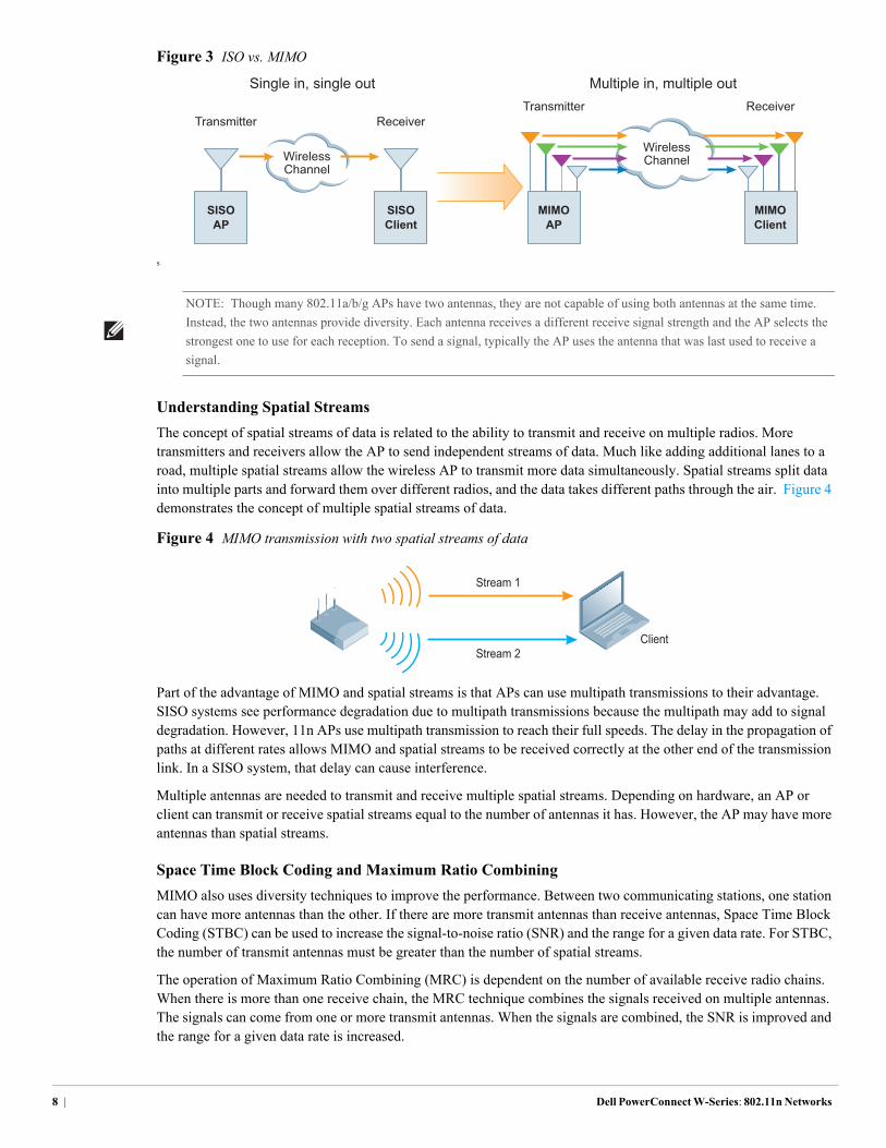
Figure 3 ISO vs. MIMO
S
Understanding Spatial Streams
The concept of spatial streams of data is related to the ability to transmit and receive on multiple radios. More transmitters and receivers allow the AP to send independent streams of data. Much like adding additional lanes to a road, multiple spatial streams allow the wireless AP to transmit more data simultaneously. Spatial streams split data into multiple parts and forward them over different radios, and the data takes different paths through the air. Figure 4 demonstrates the concept of multiple spatial streams of data.
Figure 4 MIMO transmission with two spatial streams of data
Part of the advantage of MIMO and spatial streams is that APs can use multipath transmissions to their advantage. SISO systems see performance degradation due to multipath transmissions because the multipath may add to signal degradation. However, 11n APs use multipath transmission to reach their full speeds. The delay in the propagation of paths at different rates allows MIMO and spatial streams to be received correctly at the other end of the transmission link. In a SISO system, that delay can cause interference.
Multiple antennas are needed to transmit and receive multiple spatial streams. Depending on hardware, an AP or client can transmit or receive spatial streams equal to the number of antennas it has. However, the AP may have more antennas than spatial streams.
Space Time Block Coding and Maximum Ratio Combining
MIMO also uses diversity techniques to improve the performance. Between two communicating stations, one station can have more antennas than the other. If there are more transmit antennas than receive antennas, Space Time Block Coding (STBC) can be used to increase the signal-to-noise ratio (SNR) and the range for a given data rate. For STBC, the number of transmit antennas must be greater than the number of spatial streams.
The operation of Maximum Ratio Combining (MRC) is dependent on the number of available receive radio chains. When there is more than one receive chain, the MRC technique combines the signals received on multiple antennas. The signals can come from one or more transmit antennas. When the signals are combined, the SNR is improved and the range for a given data rate is increased.
WirelessChannel
WirelessChannel
Transmitter
SISOAP
Receiver
SISOClient
Single in, single out Multiple in, multiple outTransmitter Receiver
MIMOAP
MIMOClient
NOTE: Though many 802.11a/b/g APs have two antennas, they are not capable of using both antennas at the same time.
Instead, the two antennas provide diversity. Each antenna receives a different receive signal strength and the AP selects the
strongest one to use for each reception. To send a signal, typically the AP uses the antenna that was last used to receive a
signal.
Stream 1
Stream 2Client
8 | Dell PowerConnect W-Series: 802.11n Networks
40 MHz Channels
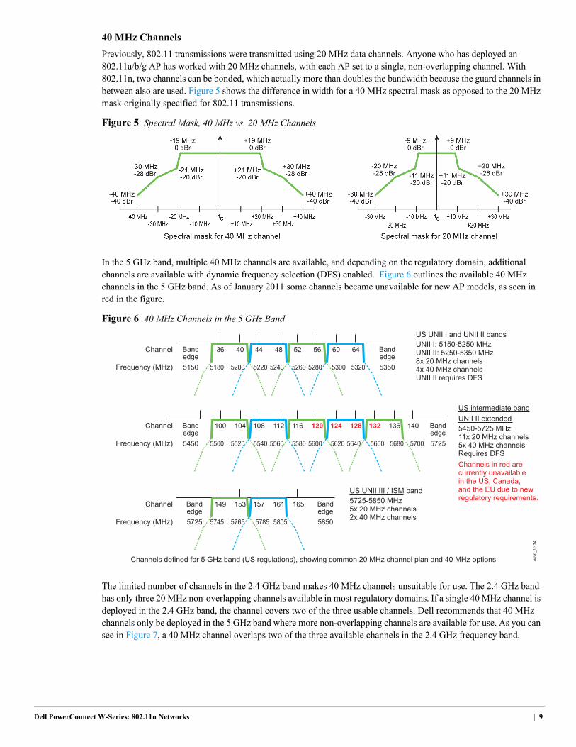
Previously, 802.11 transmissions were transmitted using 20 MHz data channels. Anyone who has deployed an 802.11a/b/g AP has worked with 20 MHz channels, with each AP set to a single, non-overlapping channel. With 802.11n, two channels can be bonded, which actually more than doubles the bandwidth because the guard channels in between also are used. Figure 5 shows the difference in width for a 40 MHz spectral mask as opposed to the 20 MHz mask originally specified for 802.11 transmissions.
Figure 5 Spectral Mask, 40 MHz vs. 20 MHz Channels
In the 5 GHz band, multiple 40 MHz channels are available, and depending on the regulatory domain, additional channels are available with dynamic frequency selection (DFS) enabled. Figure 6 outlines the available 40 MHz channels in the 5 GHz band. As of January 2011 some channels became unavailable for new AP models, as seen in red in the figure.
Figure 6 40 MHz Channels in the 5 GHz Band
The limited number of channels in the 2.4 GHz band makes 40 MHz channels unsuitable for use. The 2.4 GHz band has only three 20 MHz non-overlapping channels available in most regulatory domains. If a single 40 MHz channel is deployed in the 2.4 GHz band, the channel covers two of the three usable channels. Dell recommends that 40 MHz channels only be deployed in the 5 GHz band where more non-overlapping channels are available for use. As you can see in Figure 7, a 40 MHz channel overlaps two of the three available channels in the 2.4 GHz frequency band.
arun_0314
36 40
5180
Bandedge
Channel
Frequency (MHz)
Bandedge
5150 53505200
44 48
5220 5240
52 56
5260 5280
60 64
5300 5320
149 153
5745
Bandedge
Channel
Frequency (MHz)
Bandedge
US UNII I and UNII II bandsUNII I: 5150-5250 MHzUNII II: 5250-5350 MHz8x 20 MHz channels4x 40 MHz channelsUNII II requires DFS
UNII II extendedUS intermediate band
5450-5725 MHz11x 20 MHz channels5x 40 MHz channelsRequires DFS Channels in red are currently unavailablein the US, Canada, and the EU due to new regulatory requirements.
US UNII III / ISM band
Channels defined for 5 GHz band (US regulations), showing common 20 MHz channel plan and 40 MHz options
5725-5850 MHz5x 20 MHz channels2x 40 MHz channels5725 58505765
157 161 165
5785 5805
100 104
5500
Bandedge
Channel
Frequency (MHz)
Bandedge
5450 57255520
108 112
5540 5560
116 120
5580 5600
124 128
5620 5640
132 136 140
5660 5680 5700
Dell PowerConnect W-Series: 802.11n Networks | 9
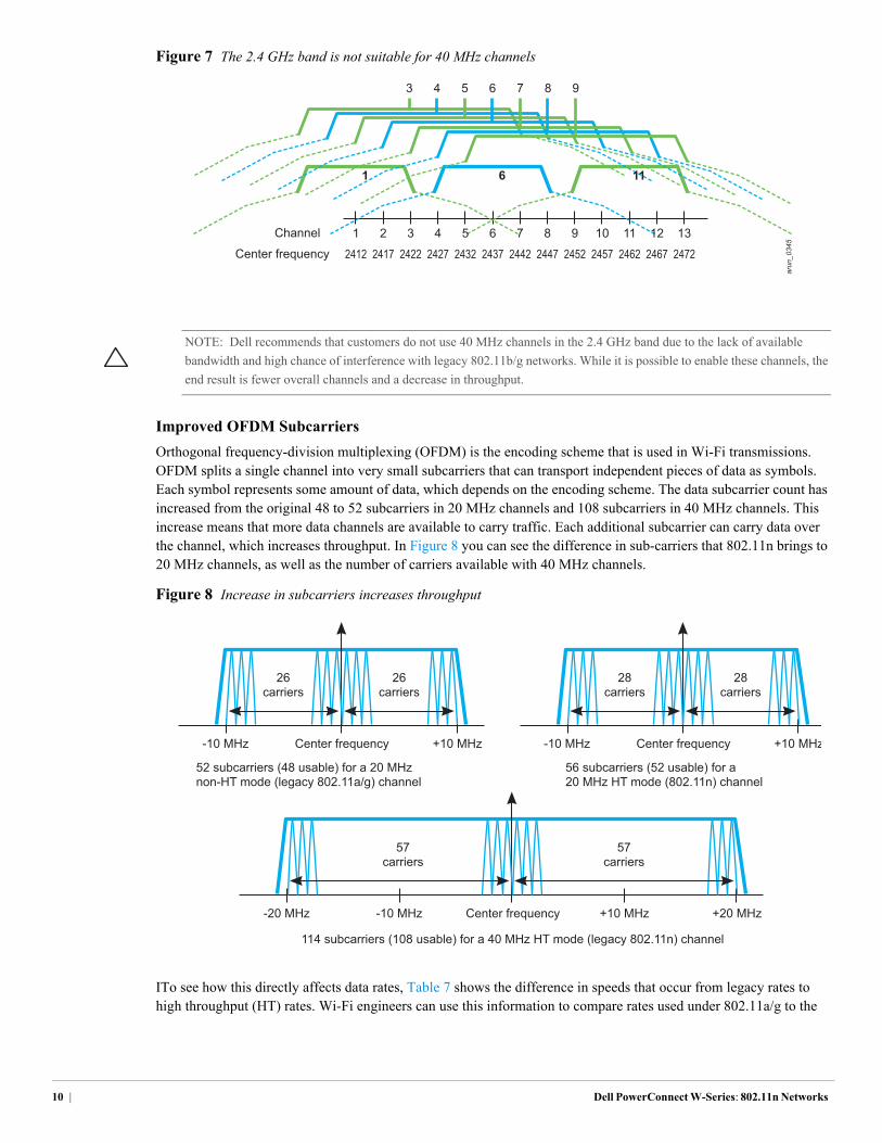
Figure 7 The 2.4 GHz band is not suitable for 40 MHz channels
Improved OFDM Subcarriers
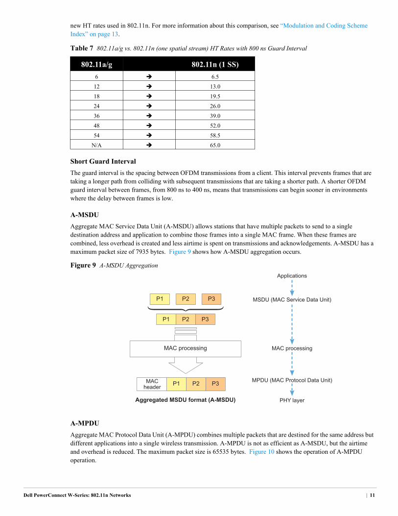
Orthogonal frequency-division multiplexing (OFDM) is the encoding scheme that is used in Wi-Fi transmissions. OFDM splits a single channel into very small subcarriers that can transport independent pieces of data as symbols. Each symbol represents some amount of data, which depends on the encoding scheme. The data subcarrier count has increased from the original 48 to 52 subcarriers in 20 MHz channels and 108 subcarriers in 40 MHz channels. This increase means that more data channels are available to carry traffic. Each additional subcarrier can carry data over the channel, which increases throughput. In Figure 8 you can see the difference in sub-carriers that 802.11n brings to 20 MHz channels, as well as the number of carriers available with 40 MHz channels.
Figure 8 Increase in subcarriers increases throughput
ITo see how this directly affects data rates, Table 7 shows the difference in speeds that occur from legacy rates to high throughput (HT) rates. Wi-Fi engineers can use this information to compare rates used under 802.11a/g to the
arun_0345
Channel 1 2 3 4 5 6
1 6
7 8 9 10 11
11
12 13
Center frequency 2412 2417 2422 2427 2432 2437 2442 2447 2452 2457 2462 2467 2472
3 4 5 6 7 8 9
NOTE: Dell recommends that customers do not use 40 MHz channels in the 2.4 GHz band due to the lack of available
bandwidth and high chance of interference with legacy 802.11b/g networks. While it is possible to enable these channels, the
end result is fewer overall channels and a decrease in throughput.
57carriers
-20 MHz -10 MHz +20 MHz+10 MHzCenter frequency
57carriers
28carriers
-10 MHz +10 MHz
28carriers
26carriers
-10 MHz +10 MHz Center frequencyCenter frequency
26carriers
52 subcarriers (48 usable) for a 20 MHznon-HT mode (legacy 802.11a/g) channel
114 subcarriers (108 usable) for a 40 MHz HT mode (legacy 802.11n) channel
56 subcarriers (52 usable) for a 20 MHz HT mode (802.11n) channel
10 | Dell PowerConnect W-Series: 802.11n Networks
new HT rates used in 802.11n. For more information about this comparison, see “Modulation and Coding Scheme Index” on page 13.
Short Guard Interval
The guard interval is the spacing between OFDM transmissions from a client. This interval prevents frames that are taking a longer path from colliding with subsequent transmissions that are taking a shorter path. A shorter OFDM guard interval between frames, from 800 ns to 400 ns, means that transmissions can begin sooner in environments where the delay between frames is low.
A-MSDU
Aggregate MAC Service Data Unit (A-MSDU) allows stations that have multiple packets to send to a single destination address and application to combine those frames into a single MAC frame. When these frames are combined, less overhead is created and less airtime is spent on transmissions and acknowledgements. A-MSDU has a maximum packet size of 7935 bytes. Figure 9 shows how A-MSDU aggregation occurs.
Figure 9 A-MSDU Aggregation
A-MPDU
Aggregate MAC Protocol Data Unit (A-MPDU) combines multiple packets that are destined for the same address but different applications into a single wireless transmission. A-MPDU is not as efficient as A-MSDU, but the airtime and overhead is reduced. The maximum packet size is 65535 bytes. Figure 10 shows the operation of A-MPDU operation.
Table 7 802.11a/g vs. 802.11n (one spatial stream) HT Rates with 800 ns Guard Interval
802.11a/g 802.11n (1 SS)
6 6.5
12 13.0
18 19.5
24 26.0
36 39.0
48 52.0
54 58.5
N/A 65.0
Applications
MSDU (MAC Service Data Unit)
MAC processing
MPDU (MAC Protocol Data Unit)
PHY layer
MAC processing
Aggregated MSDU format (A-MSDU)
P1 P2 P3
P3P2P1
P3P2P1MACheader
Dell PowerConnect W-Series: 802.11n Networks | 11
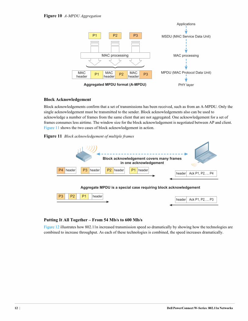
Figure 10 A-MPDU Aggregation
Block Acknowledgement
Block acknowledgements confirm that a set of transmissions has been received, such as from an A-MPDU. Only the single acknowledgement must be transmitted to the sender. Block acknowledgements also can be used to acknowledge a number of frames from the same client that are not aggregated. One acknowledgement for a set of frames consumes less airtime. The window size for the block acknowledgement is negotiated between AP and client. Figure 11 shows the two cases of block acknowledgement in action.
Figure 11 Block acknowledgement of multiple frames
Putting It All Together – From 54 Mb/s to 600 Mb/s
Figure 12 illustrates how 802.11n increased transmission speed so dramatically by showing how the technologies are combined to increase throughput. As each of these technologies is combined, the speed increases dramatically.
Applications
MSDU (MAC Service Data Unit)
MAC processing
MPDU (MAC Protocol Data Unit)
PHY layer
MAC processing
Aggregated MPDU format (A-MPDU)
P1 P2 P3
P3P2P1MACheader
MACheader
MACheader
Aggregate MPDU is a special case requiring block acknowledgement
Block acknowledgement covers many framesin one acknowledgement
P4 header
P1P2P3 headerheader Ack P1, P2, ... P3
header Ack P1, P2, ... P4P3 header P2 header P1 header
12 | Dell PowerConnect W-Series: 802.11n Networks
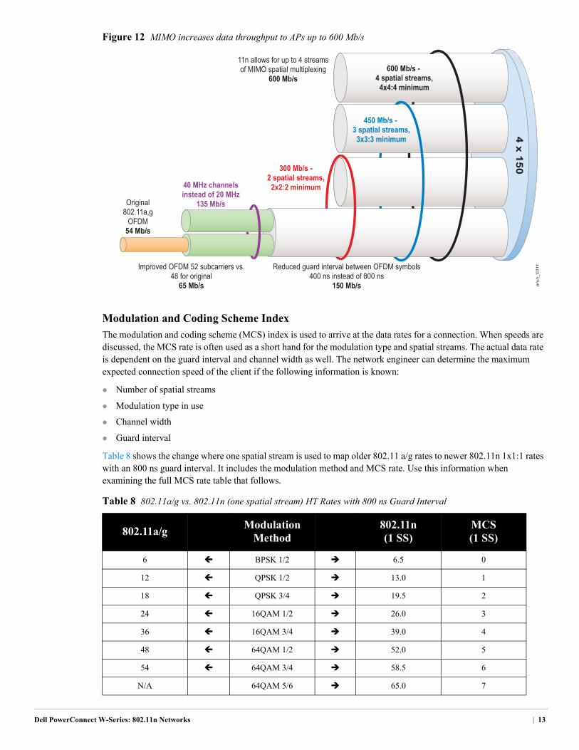
Figure 12 MIMO increases data throughput to APs up to 600 Mb/s
Modulation and Coding Scheme Index
The modulation and coding scheme (MCS) index is used to arrive at the data rates for a connection. When speeds are discussed, the MCS rate is often used as a short hand for the modulation type and spatial streams. The actual data rate is dependent on the guard interval and channel width as well. The network engineer can determine the maximum expected connection speed of the client if the following information is known:
Number of spatial streams
Modulation type in use
Channel width
Guard interval
Table 8 shows the change where one spatial stream is used to map older 802.11 a/g rates to newer 802.11n 1x1:1 rates with an 800 ns guard interval. It includes the modulation method and MCS rate. Use this information when examining the full MCS rate table that follows.
Table 8 802.11a/g vs. 802.11n (one spatial stream) HT Rates with 800 ns Guard Interval
802.11a/gModulation
Method802.11n (1 SS)
MCS (1 SS)
6 BPSK 1/2 6.5 0
12 QPSK 1/2 13.0 1
18 QPSK 3/4 19.5 2
24 16QAM 1/2 26.0 3
36 16QAM 3/4 39.0 4
48 64QAM 1/2 52.0 5
54 64QAM 3/4 58.5 6
N/A 64QAM 5/6 65.0 7
arun_0311
4 x 150300 Mb/s -2 spatial streams,
2x2:2 minimum
450 Mb/s - 3 spatial streams,
3x3:3 minimum
600 Mb/s - 4 spatial streams,
4x4:4 minimum
Original802.11a,g
OFDM54 Mb/s
Improved OFDM 52 subcarriers vs.48 for original
65 Mb/s
40 MHz channelsinstead of 20 MHz
135 Mb/s
Reduced guard interval between OFDM symbols400 ns instead of 800 ns
150 Mb/s
11n allows for up to 4 streamsof MIMO spatial multiplexing
600 Mb/s
Dell PowerConnect W-Series: 802.11n Networks | 13
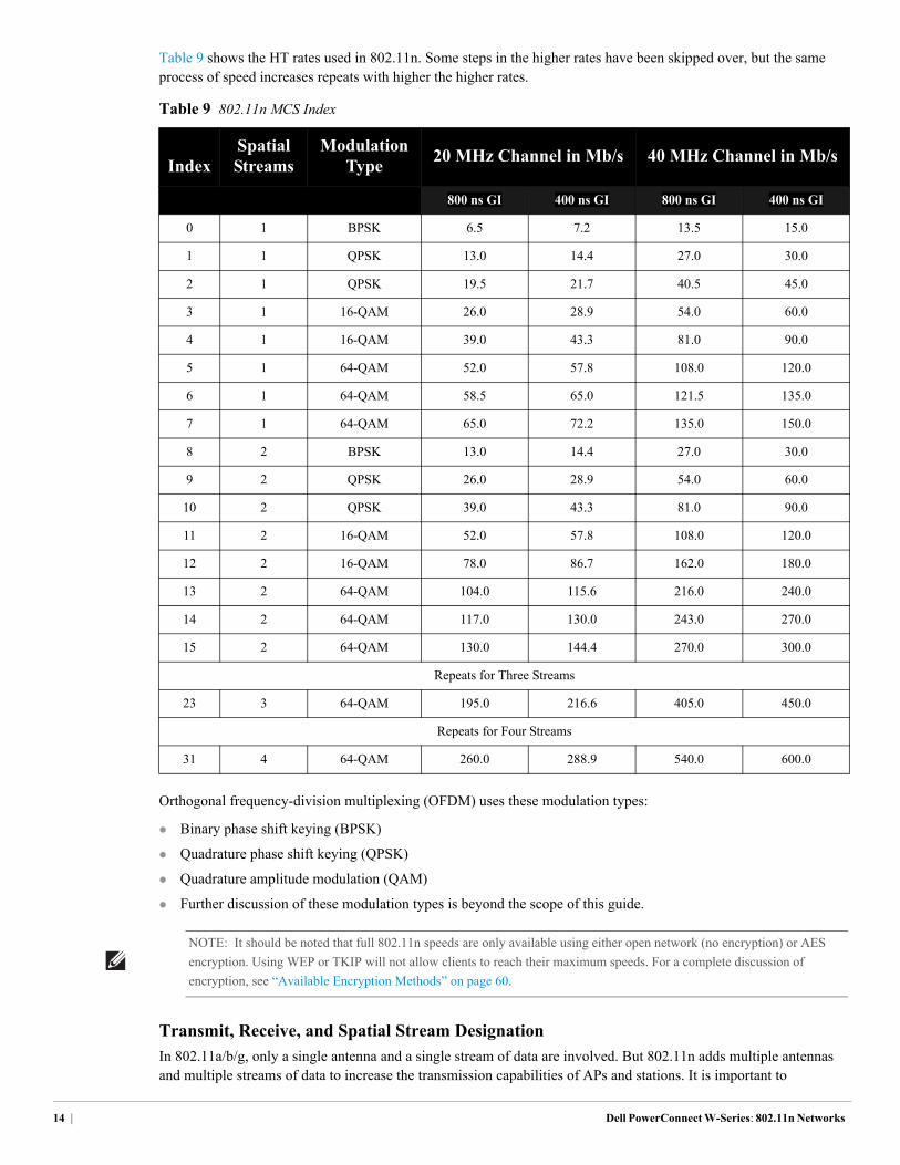
Table 9 shows the HT rates used in 802.11n. Some steps in the higher rates have been skipped over, but the same process of speed increases repeats with higher the higher rates.
Orthogonal frequency-division multiplexing (OFDM) uses these modulation types:
Binary phase shift keying (BPSK)
Quadrature phase shift keying (QPSK)
Quadrature amplitude modulation (QAM)
Further discussion of these modulation types is beyond the scope of this guide.
Transmit, Receive, and Spatial Stream Designation
In 802.11a/b/g, only a single antenna and a single stream of data are involved. But 802.11n adds multiple antennas and multiple streams of data to increase the transmission capabilities of APs and stations. It is important to
Table 9 802.11n MCS Index
IndexSpatial Streams
Modulation Type
20 MHz Channel in Mb/s 40 MHz Channel in Mb/s
800 ns GI 400 ns GI 800 ns GI 400 ns GI
0 1 BPSK 6.5 7.2 13.5 15.0
1 1 QPSK 13.0 14.4 27.0 30.0
2 1 QPSK 19.5 21.7 40.5 45.0
3 1 16-QAM 26.0 28.9 54.0 60.0
4 1 16-QAM 39.0 43.3 81.0 90.0
5 1 64-QAM 52.0 57.8 108.0 120.0
6 1 64-QAM 58.5 65.0 121.5 135.0
7 1 64-QAM 65.0 72.2 135.0 150.0
8 2 BPSK 13.0 14.4 27.0 30.0
9 2 QPSK 26.0 28.9 54.0 60.0
10 2 QPSK 39.0 43.3 81.0 90.0
11 2 16-QAM 52.0 57.8 108.0 120.0
12 2 16-QAM 78.0 86.7 162.0 180.0
13 2 64-QAM 104.0 115.6 216.0 240.0
14 2 64-QAM 117.0 130.0 243.0 270.0
15 2 64-QAM 130.0 144.4 270.0 300.0
Repeats for Three Streams
23 3 64-QAM 195.0 216.6 405.0 450.0
Repeats for Four Streams
31 4 64-QAM 260.0 288.9 540.0 600.0
NOTE: It should be noted that full 802.11n speeds are only available using either open network (no encryption) or AES
encryption. Using WEP or TKIP will not allow clients to reach their maximum speeds. For a complete discussion of
encryption, see “Available Encryption Methods” on page 60.
14 | Dell PowerConnect W-Series: 802.11n Networks
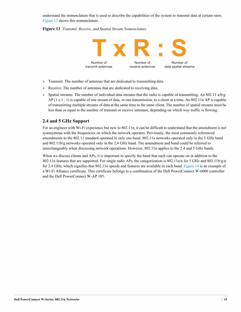
understand the nomenclature that is used to describe the capabilities of the system to transmit data at certain rates. Figure 13 shows this nomenclature.
Figure 13 Transmit, Receive, and Spatial Stream Nomenclature
Transmit: The number of antennas that are dedicated to transmitting data.
Receive: The number of antennas that are dedicated to receiving data.
Spatial streams: The number of individual data streams that the radio is capable of transmitting. An 802.11 a/b/g AP (1 x 1 : 1) is capable of one stream of data, or one transmission, to a client at a time. An 802.11n AP is capable of transmitting multiple streams of data at the same time to the same client. The number of spatial streams must be less than or equal to the number of transmit or receive antennas, depending on which way traffic is flowing.
2.4 and 5 GHz Support
For an engineer with Wi-Fi experience but new to 802.11n, it can be difficult to understand that the amendment is not synonymous with the frequencies on which the network operates. Previously, the most commonly referenced amendments to the 802.11 standard operated in only one band. 802.11a networks operated only in the 5 GHz band and 802.11b/g networks operated only in the 2.4 GHz band. The amendment and band could be referred to interchangeably when discussing network operations. However, 802.11n applies to the 2.4 and 5 GHz bands.
When we discuss clients and APs, it is important to specify the band that each can operate on in addition to the 802.11n features that are supported. For single radio APs, the categorization is 802.11a/n for 5 GHz and 802.11b/g/n for 2.4 GHz, which signifies that 802.11n speeds and features are available in each band. Figure 14 is an example of a Wi-Fi Alliance certificate. This certificate belongs to a combination of the Dell PowerConnect W-6000 controller and the Dell PowerConnect W-AP 105.
Number oftransmit antennas
Number ofreceive antennas
Number ofdata spatial streams
Dell PowerConnect W-Series: 802.11n Networks | 15
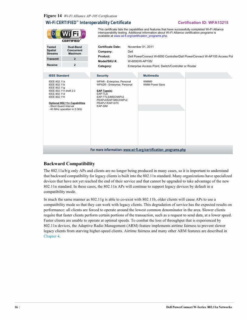
Figure 14 Wi-Fi Alliance AP-105 Certification
Backward Compatibility
The 802.11a/b/g only APs and clients are no longer being produced in many cases, so it is important to understand that backward compatibility for legacy clients is built into the 802.11n standard. Many organizations have specialized devices that have not yet reached the end of their service and that cannot be upgraded to take advantage of the new 802.11n standard. In these cases, the 802.11n APs will continue to support legacy devices by default in a compatibility mode.
In much the same manner as 802.11g is able to co-exist with 802.11b, older clients will cause APs to use a compatibility mode so that they can work with legacy clients. This degradation of service has the expected results on performance: all clients are forced to operate around the lowest common denominator in the area. Slower clients require that faster clients perform certain portions of the transaction, such as a request to send data, at a lower speed. Faster clients are unable to operate at optimal speeds. To combat the loss of throughput that is experienced by 802.11n devices, the Adaptive Radio Management (ARM) feature implements airtime fairness to prevent slower legacy clients from starving higher-speed clients. Airtime fairness and many other ARM features are described in Chapter 4.
Certification ID: WFA13215This certificate lists the capabilities and features that have successfully completed Wi-Fi Allianceinteroperability testing. Additional information about Wi-Fi Alliance certification programs isavailable at www.wi-fi.org/certification_programs.php.
Tested Dual-BandSpatial ConcurrentStreams Maximum
Transmit 2
Receive 2
Certificate Date: November 01, 2011Company: DellProduct: Dell PowerConnect W-6000 Controller/Dell PowerConnect W-AP105 Access PoiModel/SKU #: W-6000/W-AP105/Category: Enterprise Access Point, Switch/Controller or Router
IEEE Standard
IEEE 802.11aIEEE 802.11bIEEE 802.11gIEEE 802.11n draft 2.0IEEE 802.11dIEEE 802.11h
Optional 802.11n Capabilities- Short Guard Interval- 40 MHz operation in 5 GHz
Security
WPA® - Enterprise, PersonalWPA2® - Enterprise, Personal
EAP Type(s)EAP-TLSEAP-TTLS/MSCHAPv2PEAPv0/EAP-MSCHAPv2PEAPv1/EAP-GTCEAP-SIM
Multimedia
WMM®WMM Power Save
16 | Dell PowerConnect W-Series: 802.11n Networks
Dell PowerConnect W-Series: 802.11n Networks
Chapter 4: Adaptive Radio Management
Radio frequency (RF) spectrum is a limited and shared resource, and as many factors as possible must be controlled to provide an optimal experience for users. The Adaptive Radio Management (ARM) feature is a set of tools that allow the WLAN infrastructure to make decisions about radio resources and client connections without manual intervention by network administrators or client-side software.
Dell devices use information gathered from APs and air monitors (AMs) that scan the RF environment to provide information to the ARM algorithms and services. The infrastructure has a network-wide view of APs and clients, and this information is used to optimize the network and to provide an enhanced client experience. ARM is a part of the base ArubaOS™ and is available on all Dell PowerConnect W-series Mobility Controllers and APs.
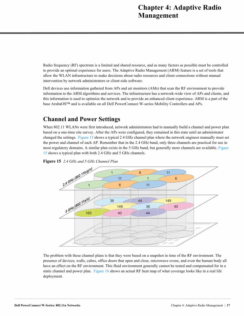
Channel and Power SettingsWhen 802.11 WLANs were first introduced, network administrators had to manually build a channel and power plan based on a one-time site survey. After the APs were configured, they remained in this state until an administrator changed the settings. Figure 15 shows a typical 2.4 GHz channel plan where the network engineer manually must set the power and channel of each AP. Remember that in the 2.4 GHz band, only three channels are practical for use in most regulatory domains. A similar plan exists in the 5 GHz band, but generally more channels are available. Figure 15 shows a typical plan with both 2.4 GHz and 5 GHz channels.
Figure 15 2.4 GHz and 5 GHz Channel Plan
The problem with these channel plans is that they were based on a snapshot in time of the RF environment. The presence of devices, walls, cubes, office doors that open and close, microwave ovens, and even the human body all have an effect on the RF environment. This fluid environment generally cannot be tested and compensated for in a static channel and power plan. Figure 16 shows an actual RF heat map of what coverage looks like in a real life deployment.
1 6 11
1 6 11
11 1 6
36 44 149
165 40 44
149 36 40
2.4 GHz (802.11b/g/n)
5 GHz (802.11a/n)
Chapter 4: Adaptive Radio Management | 17
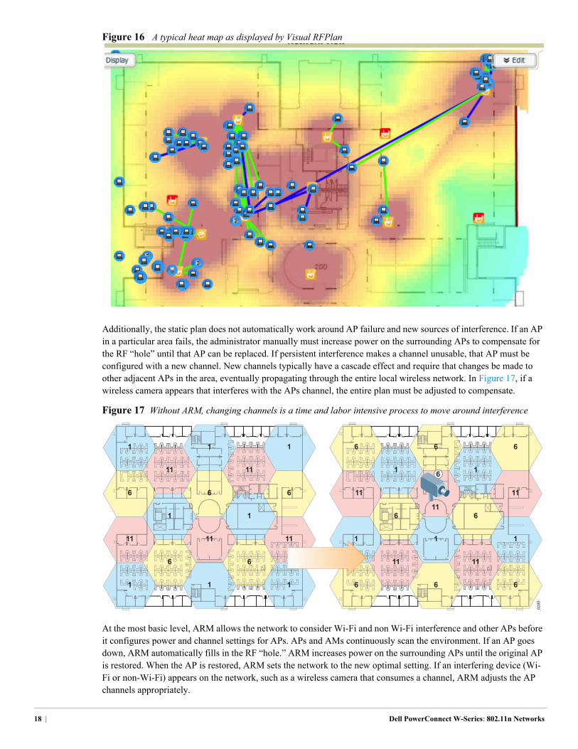
Figure 16 A typical heat map as displayed by Visual RFPlan
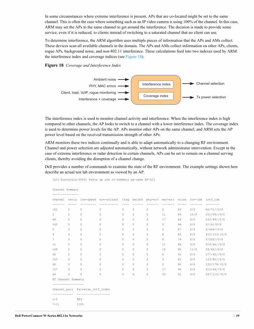
Additionally, the static plan does not automatically work around AP failure and new sources of interference. If an AP in a particular area fails, the administrator manually must increase power on the surrounding APs to compensate for the RF “hole” until that AP can be replaced. If persistent interference makes a channel unusable, that AP must be configured with a new channel. New channels typically have a cascade effect and require that changes be made to other adjacent APs in the area, eventually propagating through the entire local wireless network. In Figure 17, if a wireless camera appears that interferes with the APs channel, the entire plan must be adjusted to compensate.
Figure 17 Without ARM, changing channels is a time and labor intensive process to move around interference
At the most basic level, ARM allows the network to consider Wi-Fi and non Wi-Fi interference and other APs before it configures power and channel settings for APs. APs and AMs continuously scan the environment. If an AP goes down, ARM automatically fills in the RF “hole.” ARM increases power on the surrounding APs until the original AP is restored. When the AP is restored, ARM sets the network to the new optimal setting. If an interfering device (Wi-Fi or non-Wi-Fi) appears on the network, such as a wireless camera that consumes a channel, ARM adjusts the AP channels appropriately.
1
6
1
11
6
1
6
11
11
1
11
11
1
11
6
1
6
_0285
6
11
6
1
11
6
11
1
66
6
1
1
6
6
1
11
6
11
18 | Dell PowerConnect W-Series: 802.11n Networks
In some circumstances where extreme interference is present, APs that are co-located might be set to the same channel. This is often the case where something such as an IP video camera is using 100% of the channel. In this case, ARM may set the APs to the same channel to get around the interference. The decision is made to provide some service, even if it is reduced, to clients instead of switching to a saturated channel that no client can use.
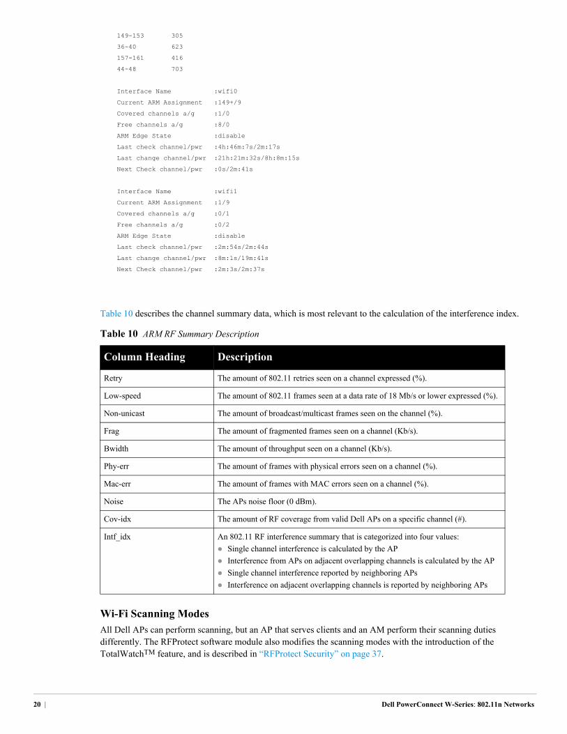
To determine interference, the ARM algorithm uses multiple pieces of information that the APs and AMs collect. These devices scan all available channels in the domain. The APs and AMs collect information on other APs, clients, rogue APs, background noise, and non-802.11 interference. These calculations feed into two indexes used by ARM: the interference index and coverage indices (see Figure 18).
Figure 18 Coverage and Interference Index
The interference index is used to monitor channel activity and interference. When the interference index is high compared to other channels, the AP looks to switch to a channel with a lower interference index. The coverage index is used to determine power levels for the AP. APs monitor other APs on the same channel, and ARM sets the AP power level based on the received transmission strength of other APs.
ARM monitors these two indices continually and is able to adapt automatically to a changing RF environment. Channel and power selection are adjusted automatically, without network administrator intervention. Except in the case of extreme interference or radar detection in certain channels, APs can be set to remain on a channel serving clients, thereby avoiding the disruption of a channel change.
Dell provides a number of commands to examine the state of the RF environment. The example settings shown here describe an actual test lab environment as viewed by an AP.
(LC1-Sunnyvale-6000) #show ap arm rf-summary ap-name AP-LC1
Channel Summary
---------------
channel retry low-speed non-unicast frag bwidth phy-err mac-err noise cov-idx intf_idx
------- ----- --------- ----------- ---- ------ ------- ------- ----- ------- --------
161 0 0 0 0 0 0 0 93 0/0 66/71//0/0
1 0 0 0 0 0 0 11 89 15/0 351/69//0/0
48 0 0 0 0 0 0 17 89 0/0 232/89//0/0
165 0 0 0 0 0 0 0 94 0/0 0/19//0/0
5 0 0 0 0 0 0 0 87 0/0 0/469//0/0
6 0 0 0 0 0 0 8 85 0/0 415/153//0/0
7 0 0 0 0 0 0 0 79 0/0 0/520//0/0
11 0 0 0 0 0 0 11 84 0/0 519/66//0/0
149 0 0 0 0 0 0 19 85 11/0 55/42//0/0
36 0 0 0 0 0 0 6 91 0/0 277/42//0/0
153 0 0 0 0 0 0 0 81 0/0 123/85//0/0
40 0 0 0 0 0 0 0 90 0/0 125/179//0/0
157 0 0 0 0 0 0 17 90 0/0 215/64//0/0
44 0 0 0 0 0 0 55 91 0/0 267/115//0/0
HT Channel Summary
------------------
channel_pair Pairwise_intf_index
------------ -------------------
1-5 889
7-11 1105
Interference indexAmbient noise
Coverage index Interference + coverage
Client, load, VoIP, rogue monitoring
PHY, MAC errorsChannel selection
Tx power selection
Dell PowerConnect W-Series:802.11n Networks | 19
149-153 305
36-40 623
157-161 416
44-48 703
Interface Name :wifi0
Current ARM Assignment :149+/9
Covered channels a/g :1/0
Free channels a/g :8/0
ARM Edge State :disable
Last check channel/pwr :4h:46m:7s/2m:17s
Last change channel/pwr :21h:21m:32s/8h:8m:15s
Next Check channel/pwr :0s/2m:41s
Interface Name :wifi1
Current ARM Assignment :1/9
Covered channels a/g :0/1
Free channels a/g :0/2
ARM Edge State :disable
Last check channel/pwr :2m:54s/2m:44s
Last change channel/pwr :8m:1s/19m:41s
Next Check channel/pwr :2m:3s/2m:37s
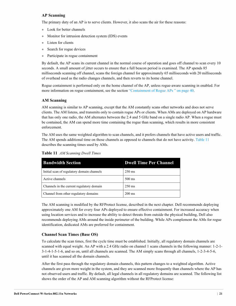
Table 10 describes the channel summary data, which is most relevant to the calculation of the interference index.
Wi-Fi Scanning Modes
All Dell APs can perform scanning, but an AP that serves clients and an AM perform their scanning duties differently. The RFProtect software module also modifies the scanning modes with the introduction of the TotalWatchTM feature, and is described in “RFProtect Security” on page 37.
Table 10 ARM RF Summary Description
Column Heading Description
Retry The amount of 802.11 retries seen on a channel expressed (%).
Low-speed The amount of 802.11 frames seen at a data rate of 18 Mb/s or lower expressed (%).
Non-unicast The amount of broadcast/multicast frames seen on the channel (%).
Frag The amount of fragmented frames seen on a channel (Kb/s).
Bwidth The amount of throughput seen on a channel (Kb/s).
Phy-err The amount of frames with physical errors seen on a channel (%).
Mac-err The amount of frames with MAC errors seen on a channel (%).
Noise The APs noise floor (0 dBm).
Cov-idx The amount of RF coverage from valid Dell APs on a specific channel (#).
Intf_idx An 802.11 RF interference summary that is categorized into four values:
Single channel interference is calculated by the AP
Interference from APs on adjacent overlapping channels is calculated by the AP
Single channel interference reported by neighboring APs
Interference on adjacent overlapping channels is reported by neighboring APs
20 | Dell PowerConnect W-Series: 802.11n Networks
AP Scanning
The primary duty of an AP is to serve clients. However, it also scans the air for these reasons:
Look for better channels
Monitor for intrusion detection system (IDS) events
Listen for clients
Search for rogue devices
Participate in rogue containment
By default, the AP scans its current channel in the normal course of operation and goes off channel to scan every 10 seconds. A small amount of jitter occurs to ensure that a full beacon period is examined. The AP spends 85 milliseconds scanning off channel, scans the foreign channel for approximately 65 milliseconds with 20 milliseconds of overhead used as the radio changes channels, and then reverts to its home channel.
Rogue containment is performed only on the home channel of the AP, unless rogue-aware scanning in enabled. For more information on rogue containment, see the section “Containment of Rogue APs ” on page 40.
AM Scanning
AM scanning is similar to AP scanning, except that the AM constantly scans other networks and does not serve clients. The AM listens, and transmits only to contain rogue APs or clients. When AMs are deployed on AP hardware that has only one radio, the AM alternates between the 2.4 and 5 GHz band on a single radio AP. When a rogue must be contained, the AM can spend more time containing the rogue than scanning, which results in more consistent enforcement.
The AM uses the same weighted algorithm to scan channels, and it prefers channels that have active users and traffic. The AM spends additional time on those channels as opposed to channels that do not have activity. Table 11 describes the scanning times used by AMs.
The AM scanning is modified by the RFProtect license, described in the next chapter. Dell recommends deploying approximately one AM for every four APs deployed to ensure effective containment. For increased accuracy when using location services and to increase the ability to detect threats from outside the physical building, Dell also recommends deploying AMs around the inside perimeter of the building. While APs complement the AMs for rogue identification, dedicated AMs are preferred for containment.
Channel Scan Times (Base OS)
To calculate the scan times, first the cycle time must be established. Initially, all regulatory domain channels are scanned with equal weight. An AP with a 2.4 GHz radio on channel 1 scans channels in the following manner: 1-2-1-3-1-4-1-5-1-6, and so on, until all channels are scanned. The AM simply scans through all channels, 1-2-3-4-5-6, until it has scanned all the domain channels.
After the first pass through the regulatory domain channels, this pattern changes to a weighted algorithm. Active channels are given more weight in the system, and they are scanned more frequently than channels where the AP has not observed users and traffic. By default, all legal channels in all regulatory domains are scanned. The following list shows the order of the AP and AM scanning algorithm without the RFProtect license:
Table 11 AM Scanning Dwell Times
Bandwidth Section Dwell Time Per Channel
Initial scan of regulatory domain channels 250 ms
Active channels 500 ms
Channels in the current regulatory domain 250 ms
Channel from other regulatory domains 200 ms
Dell PowerConnect W-Series:802.11n Networks | 21

1. Active channel
2. Active channel
3. Active channel
4. Regulatory domain channel
5. Active channel
6. Active channel
7. Active channel
8. Regulatory domain channel
9. Other regulatory domain channel
10. Active channel
11. Active channel
12. Active channel
13. Regulatory domain channel
14. Active channel
15. Active channel
16. Active channel
17. Regulatory domain channel
18. Other regulatory domain channel
19. Repeat pattern
To calculate the time it takes for all channels to be scanned after the initial scanning pass, first calculate the time needed to cycle through the entire 18 steps above, plus time spent serving clients:
(((12 active channels * scan time) + (4 regulatory channels * scan time) + (2 other
regulatory domain channels * scan time)) * .001) + 180 seconds for APs only (time
spent on channel)
Thus, an AP takes this much time:
(((12 * 85) + (4 * 85)+ (2 * 85)) * .001) + 180 = 181.53 seconds
And an AM takes this much time:
(((12 * 500) + (4 * 250)+ (2 * 200)) * .001) = 7.4 seconds
Now that the cycle time is known, it is possible to calculate the amount of time needed to cycle through all other regulatory domain channels. The AP or AM scans four regulatory domain channels per cycle. 802.11n APs also scan the 40 MHz +/- channels, which requires two scans per channel.
(Number of channels in the regulatory domain / 4 regulatory domain channel scans per
pass) * 2 for 40 MHz +/- * cycle time
An AP that needs to scan 11 2.4 GHz channels using the previous cycle time requires this much time:
(11/4) * 2 * 181.53 = 998.4 seconds, or about 16 minutes
For an AM to scan the same 11 channels requires this much time:
(11/4) * 2 * 7.4 = 40.7 seconds, or .7 minutes
22 | Dell PowerConnect W-Series: 802.11n Networks
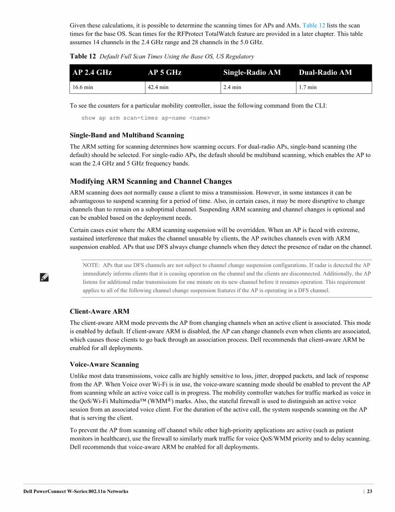
Given these calculations, it is possible to determine the scanning times for APs and AMs. Table 12 lists the scan times for the base OS. Scan times for the RFProtect TotalWatch feature are provided in a later chapter. This table assumes 14 channels in the 2.4 GHz range and 28 channels in the 5.0 GHz.
To see the counters for a particular mobility controller, issue the following command from the CLI:
show ap arm scan-times ap-name <name>
Single-Band and Multiband Scanning
The ARM setting for scanning determines how scanning occurs. For dual-radio APs, single-band scanning (the default) should be selected. For single-radio APs, the default should be multiband scanning, which enables the AP to scan the 2.4 GHz and 5 GHz frequency bands.
Modifying ARM Scanning and Channel Changes
ARM scanning does not normally cause a client to miss a transmission. However, in some instances it can be advantageous to suspend scanning for a period of time. Also, in certain cases, it may be more disruptive to change channels than to remain on a suboptimal channel. Suspending ARM scanning and channel changes is optional and can be enabled based on the deployment needs.
Certain cases exist where the ARM scanning suspension will be overridden. When an AP is faced with extreme, sustained interference that makes the channel unusable by clients, the AP switches channels even with ARM suspension enabled. APs that use DFS always change channels when they detect the presence of radar on the channel.
Client-Aware ARM
The client-aware ARM mode prevents the AP from changing channels when an active client is associated. This mode is enabled by default. If client-aware ARM is disabled, the AP can change channels even when clients are associated, which causes those clients to go back through an association process. Dell recommends that client-aware ARM be enabled for all deployments.
Voice-Aware Scanning
Unlike most data transmissions, voice calls are highly sensitive to loss, jitter, dropped packets, and lack of response from the AP. When Voice over Wi-Fi is in use, the voice-aware scanning mode should be enabled to prevent the AP from scanning while an active voice call is in progress. The mobility controller watches for traffic marked as voice in the QoS/Wi-Fi Multimedia™ (WMM®) marks. Also, the stateful firewall is used to distinguish an active voice session from an associated voice client. For the duration of the active call, the system suspends scanning on the AP that is serving the client.
To prevent the AP from scanning off channel while other high-priority applications are active (such as patient monitors in healthcare), use the firewall to similarly mark traffic for voice QoS/WMM priority and to delay scanning. Dell recommends that voice-aware ARM be enabled for all deployments.
Table 12 Default Full Scan Times Using the Base OS, US Regulatory
AP 2.4 GHz AP 5 GHz Single-Radio AM Dual-Radio AM
16.6 min 42.4 min 2.4 min 1.7 min
NOTE: APs that use DFS channels are not subject to channel change suspension configurations. If radar is detected the AP
immediately informs clients that it is ceasing operation on the channel and the clients are disconnected. Additionally, the AP
listens for additional radar transmissions for one minute on its new channel before it resumes operation. This requirement
applies to all of the following channel change suspension features if the AP is operating in a DFS channel.
Dell PowerConnect W-Series:802.11n Networks | 23
Video-Aware Scanning
Much like voice-aware scanning, video-aware scanning looks for traffic that is marked as video traffic in the WMM/QoS marks. During the video transmission, scanning is paused to ensure that the client receives a high-quality video stream. Dell recommends that video-aware ARM be enabled for all deployments.
Load-Aware Scanning
In normal operation, APs scan off channel as part of their responsibilities in the WLAN. Sometimes traffic is missed, but the client simply resends that data when it fails to receive an acknowledgement. As the client and traffic load on an AP increases, these retransmissions use up increasingly scarce airtime. When traffic loads pass a configurable threshold, ARM suspends scanning on that AP. When traffic loads drop below the threshold, the AP resumes scanning. Dell recommends load-aware scanning be enabled for all deployments with the default setting of 10 Mb/s.
Power-Save-Aware Scanning
In this mode, the AP does not scan when one or more clients are in power save mode. This mode was designed primarily to handle single-mode voice handsets. As clients have evolved, almost all clients now enter power save when they are not plugged in to a power source. When clients enter power save mode, the AP cannot change channels. Dell now recommends that this feature be disabled in favor of voice-aware scanning.
Rogue-Aware Scanning
Rogue-aware scanning was developed for high-security environments where rogue containment is critical. When rogue-aware scanning is enabled, the AP will change channels to contain a rogue if no clients are actively connected and client-aware ARM is enabled. Dell recommends enabling rogue-aware scanning only for high security environments, and should be enabled only in conjunction with client-aware ARM discussed earlier.
Band Steering
ARM band steering deals with a specific problem related to device drivers in devices that are capable of functioning in both bands. On most dual-band capable client devices, the driver looks for a connection in the 2.4 GHz band before it looks for one in 5 GHz. Even though the device can operate in both bands, 2.4 GHz is the most commonly available band, so the device searches for a connection in that band first. Clients may also see a stronger signal from 2.4 GHz when they are on the edge of the coverage range for the WLAN.
The band steering function identifies the devices that are dual-band capable, and it responds to those devices only on the 5 GHz band. The band steering feature can either encourage or force devices to move to the 5 GHz band, which has more channels available, has more bandwidth, and causes less interference for users.
NOTE: Band steering requires equal coverage between 2.4 GHz and 5 GHz bands to be effective. A larger 2.4 GHz
coverage model results in unpredictable results for clients, especially if the force 5 GHz operating mode is used. Examine the
network coverage using VisualRF™ Plan before you enable band steering in the force 5 GHz mode. New networks should be
planned using a 5 GHz coverage model and deployed with dual mode APs in each location. This deployment allows ARM to
decrease power in 2.4 GHz to compensate for the dense deployment. The over engineering of the 2.4 GHz band is required
for effective band steering use.
24 | Dell PowerConnect W-Series: 802.11n Networks
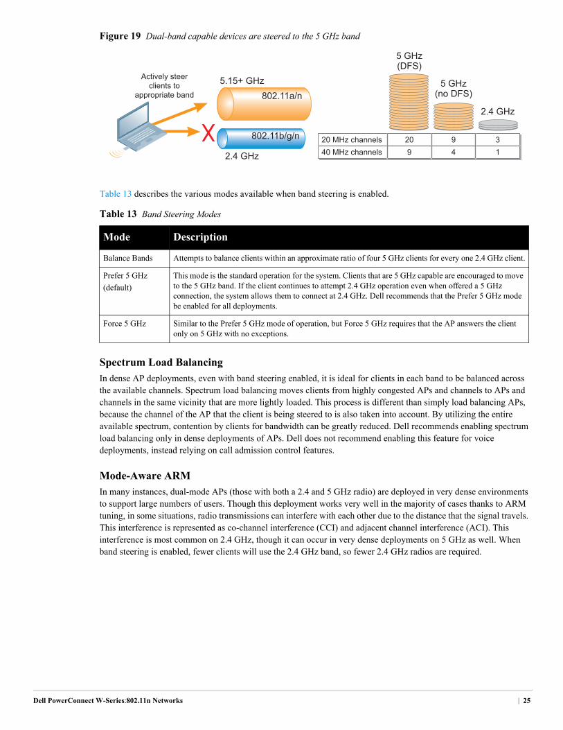
Figure 19 Dual-band capable devices are steered to the 5 GHz band
Table 13 describes the various modes available when band steering is enabled.
Spectrum Load Balancing
In dense AP deployments, even with band steering enabled, it is ideal for clients in each band to be balanced across the available channels. Spectrum load balancing moves clients from highly congested APs and channels to APs and channels in the same vicinity that are more lightly loaded. This process is different than simply load balancing APs, because the channel of the AP that the client is being steered to is also taken into account. By utilizing the entire available spectrum, contention by clients for bandwidth can be greatly reduced. Dell recommends enabling spectrum load balancing only in dense deployments of APs. Dell does not recommend enabling this feature for voice deployments, instead relying on call admission control features.
Mode-Aware ARM
In many instances, dual-mode APs (those with both a 2.4 and 5 GHz radio) are deployed in very dense environments to support large numbers of users. Though this deployment works very well in the majority of cases thanks to ARM tuning, in some situations, radio transmissions can interfere with each other due to the distance that the signal travels. This interference is represented as co-channel interference (CCI) and adjacent channel interference (ACI). This interference is most common on 2.4 GHz, though it can occur in very dense deployments on 5 GHz as well. When band steering is enabled, fewer clients will use the 2.4 GHz band, so fewer 2.4 GHz radios are required.
Table 13 Band Steering Modes
Mode Description
Balance Bands Attempts to balance clients within an approximate ratio of four 5 GHz clients for every one 2.4 GHz client.
Prefer 5 GHz
(default)
This mode is the standard operation for the system. Clients that are 5 GHz capable are encouraged to move to the 5 GHz band. If the client continues to attempt 2.4 GHz operation even when offered a 5 GHz connection, the system allows them to connect at 2.4 GHz. Dell recommends that the Prefer 5 GHz mode be enabled for all deployments.
Force 5 GHz Similar to the Prefer 5 GHz mode of operation, but Force 5 GHz requires that the AP answers the client only on 5 GHz with no exceptions.
20 MHz channels
Actively steerclients to
appropriate band
40 MHz channels20
5 GHz(DFS)
5.15+ GHz
2.4 GHz
802.11b/g/n
802.11a/n5 GHz
(no DFS)
2.4 GHz
994
31
Dell PowerConnect W-Series:802.11n Networks | 25
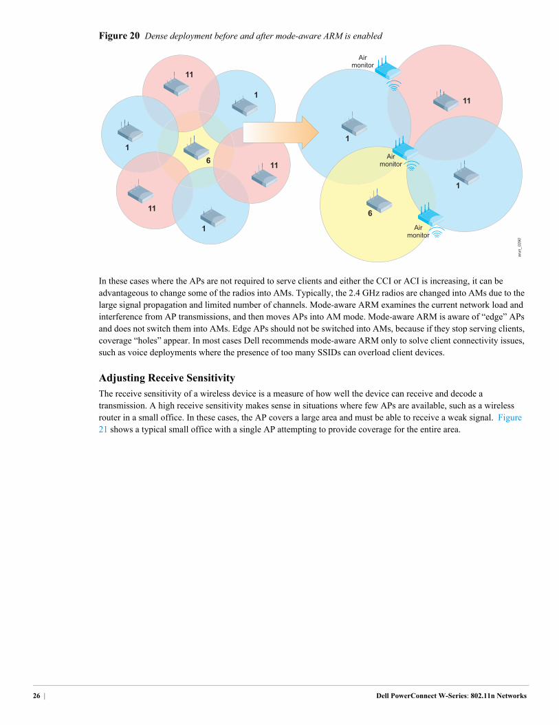
Figure 20 Dense deployment before and after mode-aware ARM is enabled
In these cases where the APs are not required to serve clients and either the CCI or ACI is increasing, it can be advantageous to change some of the radios into AMs. Typically, the 2.4 GHz radios are changed into AMs due to the large signal propagation and limited number of channels. Mode-aware ARM examines the current network load and interference from AP transmissions, and then moves APs into AM mode. Mode-aware ARM is aware of “edge” APs and does not switch them into AMs. Edge APs should not be switched into AMs, because if they stop serving clients, coverage “holes” appear. In most cases Dell recommends mode-aware ARM only to solve client connectivity issues, such as voice deployments where the presence of too many SSIDs can overload client devices.
Adjusting Receive Sensitivity
The receive sensitivity of a wireless device is a measure of how well the device can receive and decode a transmission. A high receive sensitivity makes sense in situations where few APs are available, such as a wireless router in a small office. In these cases, the AP covers a large area and must be able to receive a weak signal. Figure 21 shows a typical small office with a single AP attempting to provide coverage for the entire area.
1
1
1
6
11
11
11
arun_0290
1
11
1
6
Airmonitor
Airmonitor
Airmonitor
26 | Dell PowerConnect W-Series: 802.11n Networks
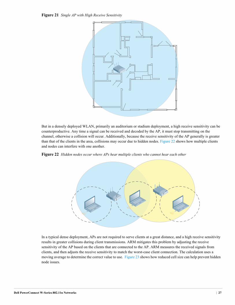
Figure 21 Single AP with High Receive Sensitivity
But in a densely deployed WLAN, primarily an auditorium or stadium deployment, a high receive sensitivity can be counterproductive. Any time a signal can be received and decoded by the AP, it must stop transmitting on the channel, otherwise a collision will occur. Additionally, because the receive sensitivity of the AP generally is greater than that of the clients in the area, collisions may occur due to hidden nodes. Figure 22 shows how multiple clients and nodes can interfere with one another.
Figure 22 Hidden nodes occur where APs hear multiple clients who cannot hear each other
In a typical dense deployment, APs are not required to serve clients at a great distance, and a high receive sensitivity results in greater collisions during client transmissions. ARM mitigates this problem by adjusting the receive sensitivity of the AP based on the clients that are connected to the AP. ARM measures the received signals from clients, and then adjusts the receive sensitivity to match the worst-case client connection. The calculation uses a moving average to determine the correct value to use. Figure 23 shows how reduced cell size can help prevent hidden node issues.
Dell PowerConnect W-Series:802.11n Networks | 27
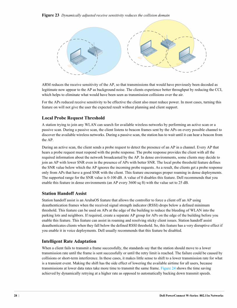
Figure 23 Dynamically adjusted receive sensitivity reduces the collision domain
ARM reduces the receive sensitivity of the AP, so that transmissions that would have previously been decoded as legitimate now appear to the AP as background noise. The clients experience better throughput by reducing the CCI, which helps to eliminate what would have been seen as transmission collisions over the air.
For the APs reduced receive sensitivity to be effective the client also must reduce power. In most cases, turning this feature on will not give the user the expected result without planning and client support.
Local Probe Request Threshold
A station trying to join any WLAN can search for available wireless networks by performing an active scan or a passive scan. During a passive scan, the client listens to beacon frames sent by the APs on every possible channel to discover the available wireless networks. During a passive scan, the station has to wait until it can hear a beacon from the AP.
During an active scan, the client sends a probe request to detect the presence of an AP in a channel. Every AP that hears a probe request must respond with the probe response. The probe response provides the client with all the required information about the network broadcasted by the AP. In dense environments, some clients may decide to join an AP with lower SNR even in the presence of APs with better SNR. The local probe threshold feature defines the SNR value below which the AP ignores the incoming probe requests. As a result, the clients get a probe response only from APs that have a good SNR with the client. This feature encourages proper roaming in dense deployments. The supported range for the SNR value is 0-100 dB. A value of 0 disables this feature. Dell recommends that you enable this feature in dense environments (an AP every 3600 sq ft) with the value set to 25 dB.
Station Handoff Assist
Station handoff assist is an ArubaOS feature that allows the controller to force a client off an AP using deauthentication frames when the received signal strength indicator (RSSI) drops below a defined minimum threshold. This feature can be used on APs at the edge of the building to reduce the bleeding of WLAN into the parking lots and neighbors. If required, create a separate AP group for APs on the edge of the building before you enable this feature. This feature can assist in roaming and resolving sticky client issues. Station handoff assist deauthenticates clients when they fall below the defined RSSI threshold. So, this feature has a very disruptive effect if you enable it in voice deployments. Dell usually recommends that this feature be disabled.
Intelligent Rate Adaptation
When a client fails to transmit a frame successfully, the standards say that the station should move to a lower transmission rate until the frame is sent successfully or until the retry limit is reached. The failure could be caused by collisions or short-term interference. In these cases, it makes little sense to shift to a lower transmission rate for what is a transient event. Making the shift has the side effect of lowering the available airtime for all users, because transmissions at lower data rates take more time to transmit the same frame. Figure 24 shows the time saving achieved by dynamically retrying at a higher rate as opposed to automatically backing down transmit speeds.
28 | Dell PowerConnect W-Series: 802.11n Networks
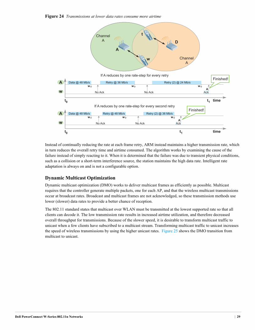
Figure 24 Transmissions at lower data rates consume more airtime
Instead of continually reducing the rate at each frame retry, ARM instead maintains a higher transmission rate, which in turn reduces the overall retry time and airtime consumed. The algorithm works by examining the cause of the failure instead of simply reacting to it. When it is determined that the failure was due to transient physical conditions, such as a collision or a short-term interference source, the station maintains the high data rate. Intelligent rate adaptation is always on and is not a configurable option.
Dynamic Multicast Optimization
Dynamic multicast optimization (DMO) works to deliver multicast frames as efficiently as possible. Multicast requires that the controller generate multiple packets, one for each AP, and that the wireless multicast transmissions occur at broadcast rates. Broadcast and multicast frames are not acknowledged, so these transmission methods use lower (slower) data rates to provide a better chance of reception.
The 802.11 standard states that multicast over WLAN must be transmitted at the lowest supported rate so that all clients can decode it. The low transmission rate results in increased airtime utilization, and therefore decreased overall throughput for transmissions. Because of the slower speed, it is desirable to transform multicast traffic to unicast when a few clients have subscribed to a multicast stream. Transforming multicast traffic to unicast increases the speed of wireless transmissions by using the higher unicast rates. Figure 25 shows the DMO transition from multicast to unicast.
ChannelA
If A reduces by one rate-step for every retry
Data @ 48 Mb/s
No Ack
D
wRetry @ 36 Mb/s
No Ack
wRetry (2) @ 24 Mb/s
w
A
AckA
t0 t1 time
w
A
If A reduces by one rate-step for every second retry
Data @ 48 Mb/s
No Ack
wRetry @ 48 Mb/s
No Ack
wRetry (2) @ 36 Mb/s
w
AckA
t0 t1 time
Finished!
Finished!
w
A
t
w
ChannelA
Dell PowerConnect W-Series:802.11n Networks | 29
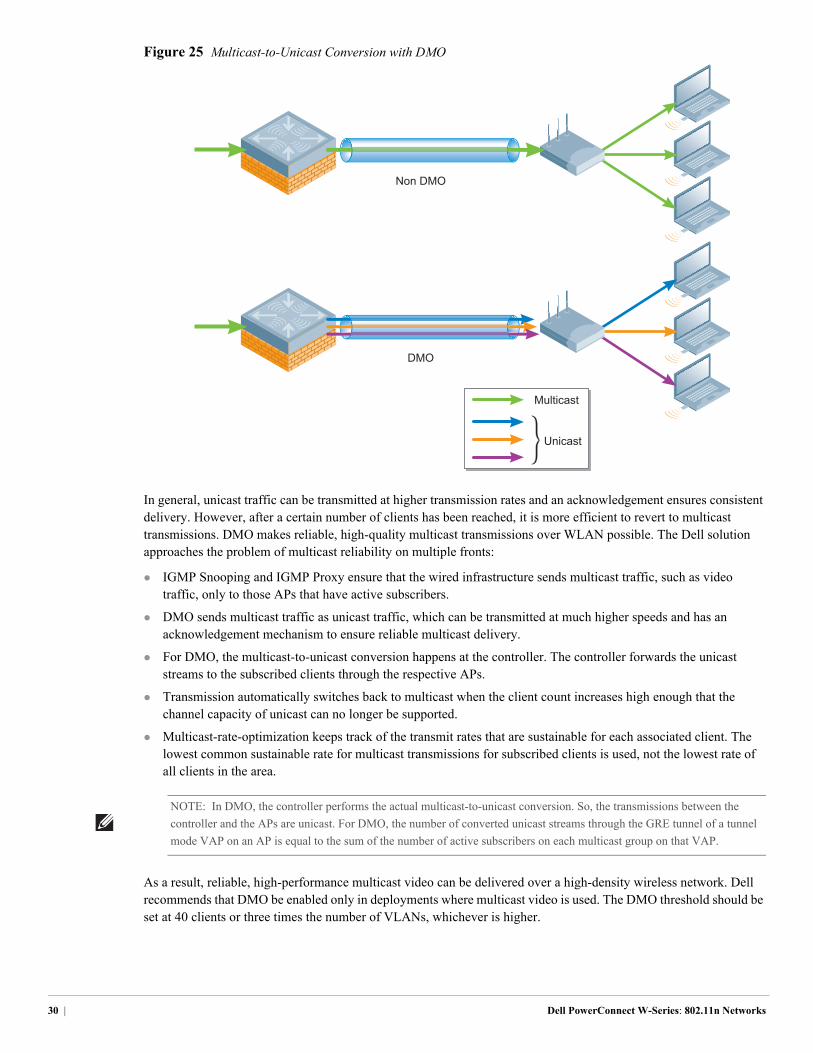
Figure 25 Multicast-to-Unicast Conversion with DMO
In general, unicast traffic can be transmitted at higher transmission rates and an acknowledgement ensures consistent delivery. However, after a certain number of clients has been reached, it is more efficient to revert to multicast transmissions. DMO makes reliable, high-quality multicast transmissions over WLAN possible. The Dell solution approaches the problem of multicast reliability on multiple fronts:
IGMP Snooping and IGMP Proxy ensure that the wired infrastructure sends multicast traffic, such as video traffic, only to those APs that have active subscribers.
DMO sends multicast traffic as unicast traffic, which can be transmitted at much higher speeds and has an acknowledgement mechanism to ensure reliable multicast delivery.
For DMO, the multicast-to-unicast conversion happens at the controller. The controller forwards the unicast streams to the subscribed clients through the respective APs.
Transmission automatically switches back to multicast when the client count increases high enough that the channel capacity of unicast can no longer be supported.
Multicast-rate-optimization keeps track of the transmit rates that are sustainable for each associated client. The lowest common sustainable rate for multicast transmissions for subscribed clients is used, not the lowest rate of all clients in the area.
As a result, reliable, high-performance multicast video can be delivered over a high-density wireless network. Dell recommends that DMO be enabled only in deployments where multicast video is used. The DMO threshold should be set at 40 clients or three times the number of VLANs, whichever is higher.
Non DMO
DMO
Multicast
Unicast
NOTE: In DMO, the controller performs the actual multicast-to-unicast conversion. So, the transmissions between the
controller and the APs are unicast. For DMO, the number of converted unicast streams through the GRE tunnel of a tunnel
mode VAP on an AP is equal to the sum of the number of active subscribers on each multicast group on that VAP.
30 | Dell PowerConnect W-Series: 802.11n Networks
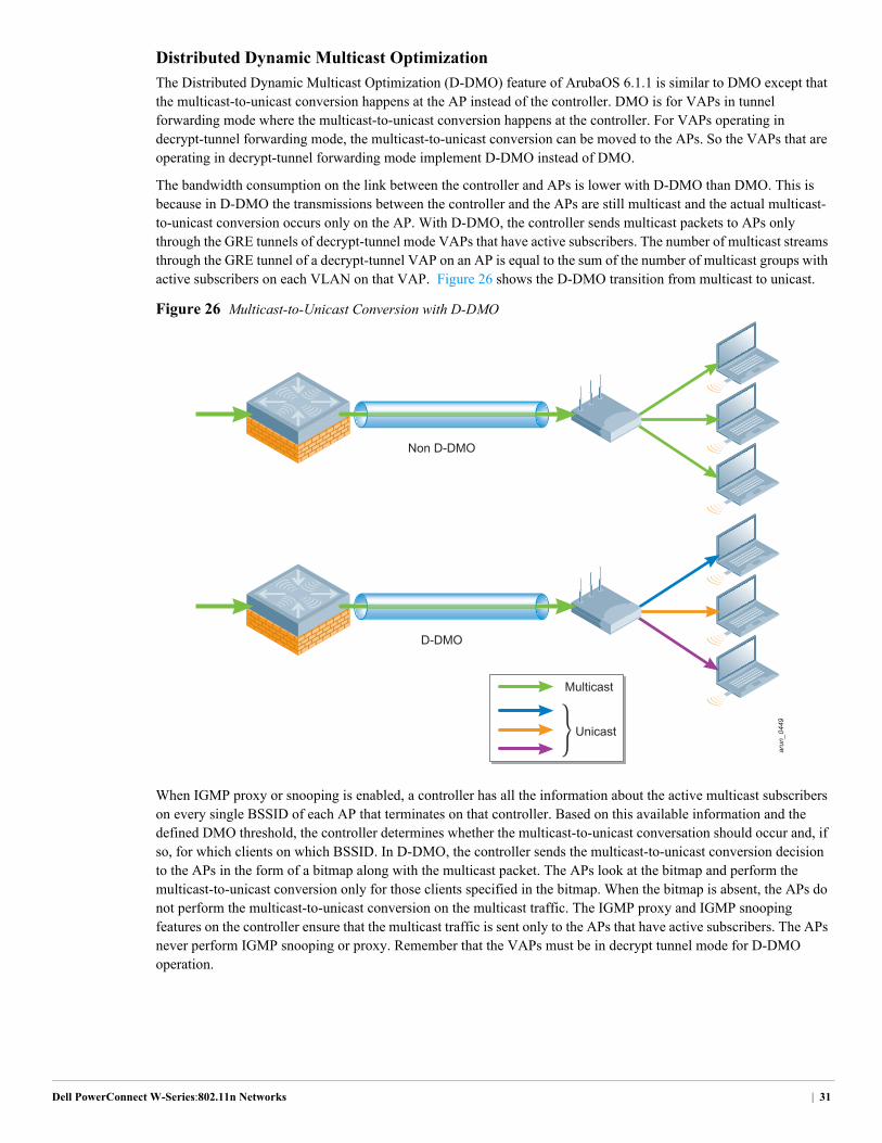
Distributed Dynamic Multicast Optimization
The Distributed Dynamic Multicast Optimization (D-DMO) feature of ArubaOS 6.1.1 is similar to DMO except that the multicast-to-unicast conversion happens at the AP instead of the controller. DMO is for VAPs in tunnel forwarding mode where the multicast-to-unicast conversion happens at the controller. For VAPs operating in decrypt-tunnel forwarding mode, the multicast-to-unicast conversion can be moved to the APs. So the VAPs that are operating in decrypt-tunnel forwarding mode implement D-DMO instead of DMO.
The bandwidth consumption on the link between the controller and APs is lower with D-DMO than DMO. This is because in D-DMO the transmissions between the controller and the APs are still multicast and the actual multicast-to-unicast conversion occurs only on the AP. With D-DMO, the controller sends multicast packets to APs only through the GRE tunnels of decrypt-tunnel mode VAPs that have active subscribers. The number of multicast streams through the GRE tunnel of a decrypt-tunnel VAP on an AP is equal to the sum of the number of multicast groups with active subscribers on each VLAN on that VAP. Figure 26 shows the D-DMO transition from multicast to unicast.
Figure 26 Multicast-to-Unicast Conversion with D-DMO
When IGMP proxy or snooping is enabled, a controller has all the information about the active multicast subscribers on every single BSSID of each AP that terminates on that controller. Based on this available information and the defined DMO threshold, the controller determines whether the multicast-to-unicast conversation should occur and, if so, for which clients on which BSSID. In D-DMO, the controller sends the multicast-to-unicast conversion decision to the APs in the form of a bitmap along with the multicast packet. The APs look at the bitmap and perform the multicast-to-unicast conversion only for those clients specified in the bitmap. When the bitmap is absent, the APs do not perform the multicast-to-unicast conversion on the multicast traffic. The IGMP proxy and IGMP snooping features on the controller ensure that the multicast traffic is sent only to the APs that have active subscribers. The APs never perform IGMP snooping or proxy. Remember that the VAPs must be in decrypt tunnel mode for D-DMO operation.
arun_0449
Non D-DMO
D-DMO
Multicast
Unicast
Dell PowerConnect W-Series:802.11n Networks | 31
In ArubaOS 6.1.1, D-DMO is supported only for decrypt-tunnel VAPS on campus APs. Dell recommends that D-DMO be enabled only in multicast video deployments where network and security policies allow the use of decrypt -tunnel VAPs. The DMO threshold should be set at 40.
Calculating the Bandwidth Consumption of DMO and D-DMO
The bandwidth consumed by DMO and D-DMO on the network between the controller and an AP depends on various factors such as
number of multicast subscribers
number of active multicast groups
number of VLANs on a VAP
number of DMO or D-DMO enabled VAPs on an AP
The bandwidth consumed is always proportional to the number of streams. So, the difference in bandwidth consumed by DMO and D-DMO can be understood easily by calculating the number of streams generated by DMO and D-DMO under various conditions.
The number of streams between the controller and a VAP for DMO can be calculated as follows:
Number of streams Number of active Number of active Number of active between the controller = multicast subscribers + multicast subscribers …… + multicast subscribers and a tunnel VAP for on group 1 on group 2 on group nDMO
Similarly, the number of streams between the controller and a decrypt-tunnel VAP for D-DMO can be calculated as follows:
Number of streams Number of active ...Number of active ...................... Number of active between the controller = multicast groups + ...........multicast groups .......…… + multicast groups and a decrypt-tunnel on VLAN 1 of the on VLAN 2 of the ................. on VLAN n of theVAP for D-DMO VAP VAP .......... VAP
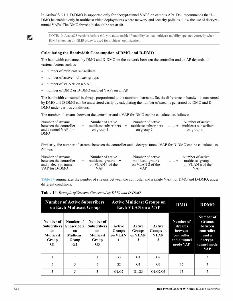
Table 14 summarizes the number of streams between the controller and a single VAP, for DMO and D-DMO, under different conditions.
NOTE: In ArubaOS versions before 6.0, you must enable IP mobility so that multicast mobility operates correctly when
IGMP snooping or IGMP proxy is used for multicast optimization.
Table 14 Example of Streams Generated by DMO and D-DMO
Number of Active Subscribers on Each Multicast Group
Active Multicast Groups on Each VLAN on a VAP
DMO DDMO
Number of Subscribers
on Multicast
Group G1
Number of Subscribers
on Multicast
Group G2
Number of Subscribers
on Multicast
Group G3
Active Groups
on VLAN 1
Active Groups
on VLAN 2
Active Groups on
VLAN 3
Number of streams between
controller and a tunnel mode VAP
Number of streams between
controller and a
decrypt- tunnel mode
VAP
1 1 1 G3 G1 G2 3 3
5 5 5 G2 G1 G3 15 3
5 5 5 G1,G2 G1,G3 G1,G2,G3 15 7
32 | Dell PowerConnect W-Series: 802.11n Networks
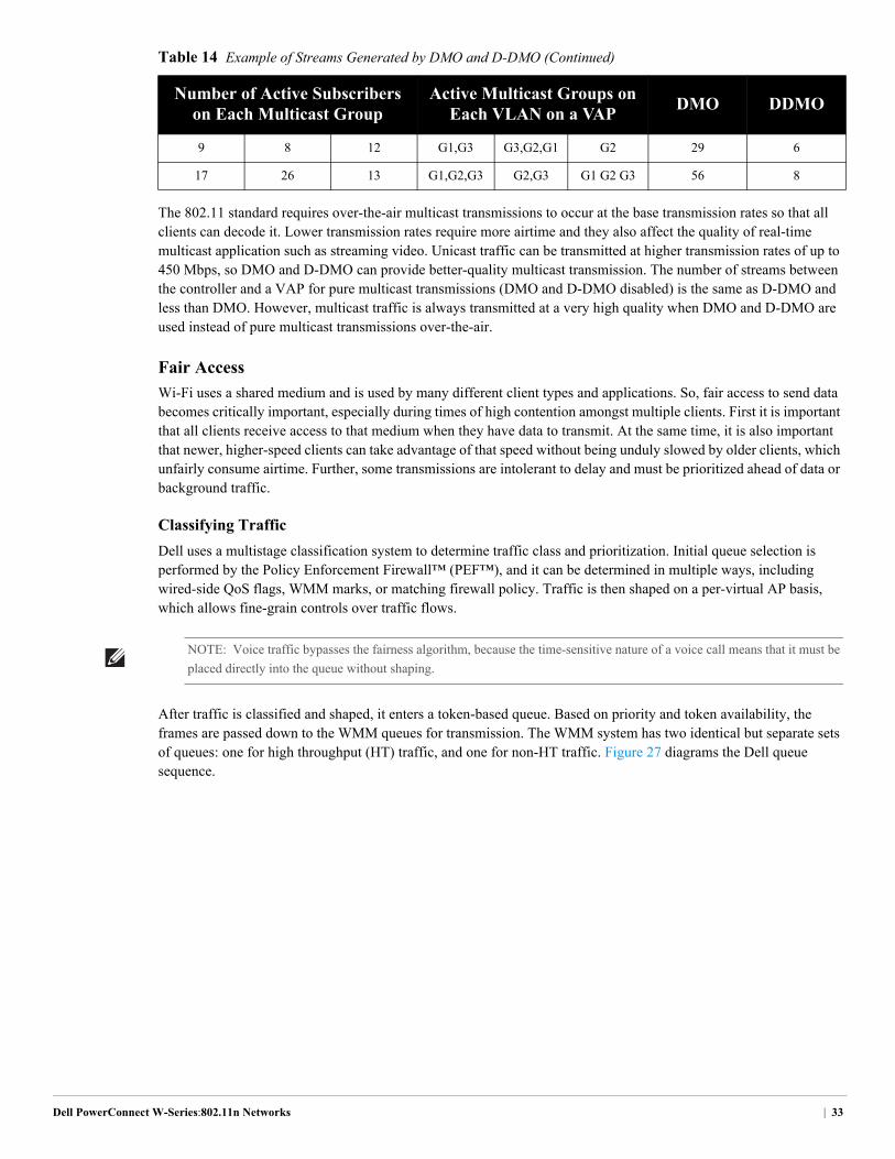
The 802.11 standard requires over-the-air multicast transmissions to occur at the base transmission rates so that all clients can decode it. Lower transmission rates require more airtime and they also affect the quality of real-time multicast application such as streaming video. Unicast traffic can be transmitted at higher transmission rates of up to 450 Mbps, so DMO and D-DMO can provide better-quality multicast transmission. The number of streams between the controller and a VAP for pure multicast transmissions (DMO and D-DMO disabled) is the same as D-DMO and less than DMO. However, multicast traffic is always transmitted at a very high quality when DMO and D-DMO are used instead of pure multicast transmissions over-the-air.
Fair Access
Wi-Fi uses a shared medium and is used by many different client types and applications. So, fair access to send data becomes critically important, especially during times of high contention amongst multiple clients. First it is important that all clients receive access to that medium when they have data to transmit. At the same time, it is also important that newer, higher-speed clients can take advantage of that speed without being unduly slowed by older clients, which unfairly consume airtime. Further, some transmissions are intolerant to delay and must be prioritized ahead of data or background traffic.
Classifying Traffic
Dell uses a multistage classification system to determine traffic class and prioritization. Initial queue selection is performed by the Policy Enforcement Firewall™ (PEF™), and it can be determined in multiple ways, including wired-side QoS flags, WMM marks, or matching firewall policy. Traffic is then shaped on a per-virtual AP basis, which allows fine-grain controls over traffic flows.
After traffic is classified and shaped, it enters a token-based queue. Based on priority and token availability, the frames are passed down to the WMM queues for transmission. The WMM system has two identical but separate sets of queues: one for high throughput (HT) traffic, and one for non-HT traffic. Figure 27 diagrams the Dell queue sequence.
9 8 12 G1,G3 G3,G2,G1 G2 29 6
17 26 13 G1,G2,G3 G2,G3 G1 G2 G3 56 8
Table 14 Example of Streams Generated by DMO and D-DMO (Continued)
Number of Active Subscribers on Each Multicast Group
Active Multicast Groups on Each VLAN on a VAP
DMO DDMO
NOTE: Voice traffic bypasses the fairness algorithm, because the time-sensitive nature of a voice call means that it must be
placed directly into the queue without shaping.
Dell PowerConnect W-Series:802.11n Networks | 33
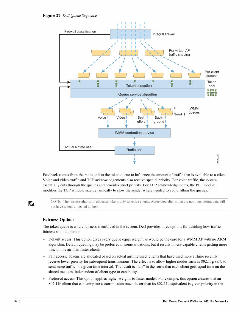
Figure 27 Dell Queue Sequence
Feedback comes from the radio unit to the token queue to influence the amount of traffic that is available to a client. Voice and video traffic and TCP acknowledgements also receive special priority. For voice traffic, the system essentially cuts through the queues and provides strict priority. For TCP acknowledgements, the PEF module modifies the TCP window size dynamically to slow the sender where needed to avoid filling the queues.
Fairness Options
The token queue is where fairness is enforced in the system. Dell provides three options for deciding how traffic fairness should operate:
Default access: This option gives every queue equal weight, as would be the case for a WMM AP with no ARM algorithm. Default queuing may be preferred in some situations, but it results in less-capable clients getting more time on the air than faster clients.
Fair access: Tokens are allocated based on actual airtime used: clients that have used more airtime recently receive lower priority for subsequent transmissions. The effect is to allow higher modes such as 802.11g vs. b to send more traffic in a given time interval. The result is “fair” in the sense that each client gets equal time on the shared medium, independent of client type or capability.
Preferred access: This option applies higher weights to faster modes. For example, this option assures that an 802.11n client that can complete a transmission much faster than its 802.11a equivalent is given priority in the
arun_0298
Actual airtime use
Voice Video Besteffort
Back-ground
Non-HT
HT WMMqueues
Per-clientqueues
Per virtual-APtraffic shaping
Integral firewall
Radio unit
Queue service algorithm
Token allocation
WMM contention service
Firewall classification
Tokenpool
NOTE: The fairness algorithm allocates tokens only to active clients. Associated clients that are not transmitting data will
not have tokens allocated to them.
34 | Dell PowerConnect W-Series: 802.11n Networks
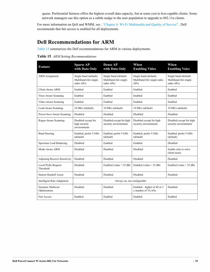
queue. Preferential fairness offers the highest overall data capacity, but at some cost to less-capable clients. Some network managers use this option as a subtle nudge to the user population to upgrade to 802.11n clients.
For more information on QoS and WMM, see , “Chapter 6: Wi-Fi Multimedia and Quality of Service” . Dell recommends that fair access is enabled for all deployments.
Dell Recommendations for ARMTable 15 summarizes the Dell recommendations for ARM in various deployments.
Table 15 ARM Setting Recommendations
FeatureSparse AP with Data Only
Dense AP with Data Only
When Enabling Video
When Enabling Voice
ARM Assignment Single band (default)Multiband (for single-radio APs)
Single band (default)Multiband (for single-radio APs)
Single band (default)Multiband (for single-radio APs)
Single band (default)Multiband (for single-radio APs)
Client-Aware ARM Enabled Enabled Enabled Enabled
Voice-Aware Scanning Enabled Enabled Enabled Enabled
Video-Aware Scanning Enabled Enabled Enabled Enabled
Load-Aware Scanning 10 Mb/s (default) 10 Mb/s (default) 10 Mb/s (default) 10 Mb/s (default)
Power-Save-Aware Scanning Disabled Disabled Disabled Disabled
Rogue-Aware Scanning Disabled except for high security environments
Disabled except for high security environments
Disabled except for high security environments
Disabled except for high security environments
Band Steering Enabled, prefer 5 GHz (default)
Enabled, prefer 5 GHz (default)
Enabled, prefer 5 GHz (default)
Enabled, prefer 5 GHz (default)
Spectrum Load Balancing Disabled Enabled Enabled Disabled
Mode-Aware ARM Disabled Disabled Disabled Enable only to solve client issues
Adjusting Receive Sensitivity Disabled Disabled Disabled Disabled
Local Probe Request Threshold
Disabled Enabled (value = 25 dB) Enabled (value = 25 dB) Enabled (value = 25 dB)
Station Handoff Assist Disabled Disabled Disabled Disabled
Intelligent Rate Adaptation ..........................................................Always on, not configurable
Dynamic Multicast Optimization
Disabled Disabled Enabled – higher of 40 or 3 x number of VLANs
Disabled
Fair Access Enabled Enabled Enabled Enabled
Dell PowerConnect W-Series:802.11n Networks | 35

36 | Dell PowerConnect W-Series: 802.11n Networks
Dell PowerConnect W-Series: 802.11n
Chapter 5: Wi-Fi Security and Spectrum Visibility with RFProtect
802.11n provides the speed that makes it possible to replace wired Ethernet connections. ARM makes sure that clients have an optimal experience. However, two functions still must be considered: RF security and visibility. The RFProtect module provides these features:
wireless intrusion detection and prevention
spectrum analysis for troubleshooting radio interference issues
RFProtect SecurityThe RFProtect feature set introduced in ArubaOS 6.0 combines the wireless intrusion prevention (WIP) software and new spectrum capabilities. RFProtect provides an integrated system that detects and mitigates threats. Many regulated industries mandate the use of wireless security for such things as payment card industry (PCI) compliance.
The RFProtect module provides these benefits:
Modifies the way AMs scan the environment
Provides a patented containment method for rogue APs
Provides an intrusion detection system (IDS) for infrastructure and clients
Network dashboards and configuration wizards make these features, and thereby network security, easy to manage.
Security Summary Dashboard
The security summary dashboard presents an overview of the security for the whole network. This dashboard (see Figure 28) provides a view into the status of APs and clients, as well as events that are occurring on the network. This dashboard allows the network administrator to filter information effectively and look closely at clients and events to understand what is actually occurring on the network.
Chapter 5: Wi-Fi Security and Spectrum Visibility with RFProtect | 37
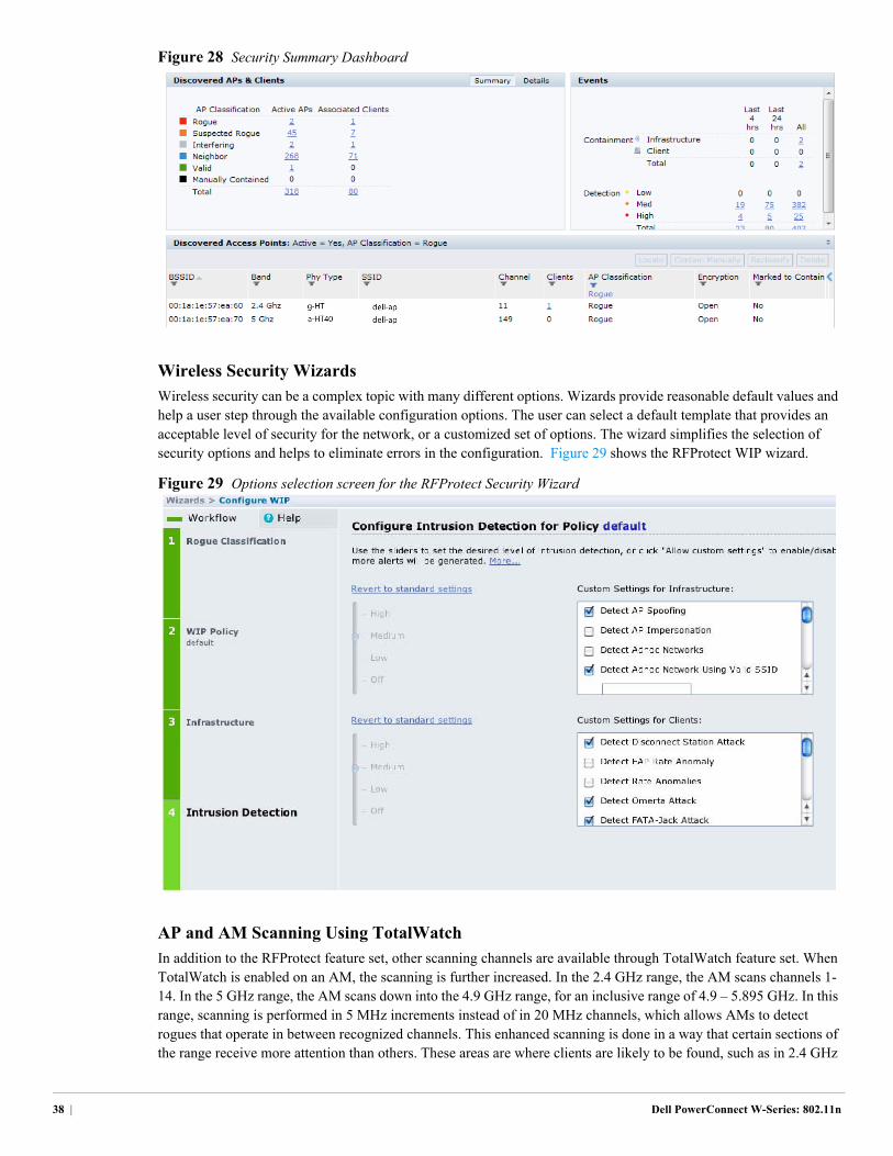
Figure 28 Security Summary Dashboard
Wireless Security Wizards
Wireless security can be a complex topic with many different options. Wizards provide reasonable default values and help a user step through the available configuration options. The user can select a default template that provides an acceptable level of security for the network, or a customized set of options. The wizard simplifies the selection of security options and helps to eliminate errors in the configuration. Figure 29 shows the RFProtect WIP wizard.
Figure 29 Options selection screen for the RFProtect Security Wizard
AP and AM Scanning Using TotalWatch
In addition to the RFProtect feature set, other scanning channels are available through TotalWatch feature set. When TotalWatch is enabled on an AM, the scanning is further increased. In the 2.4 GHz range, the AM scans channels 1-14. In the 5 GHz range, the AM scans down into the 4.9 GHz range, for an inclusive range of 4.9 – 5.895 GHz. In this range, scanning is performed in 5 MHz increments instead of in 20 MHz channels, which allows AMs to detect rogues that operate in between recognized channels. This enhanced scanning is done in a way that certain sections of the range receive more attention than others. These areas are where clients are likely to be found, such as in 2.4 GHz
38 | Dell PowerConnect W-Series: 802.11n
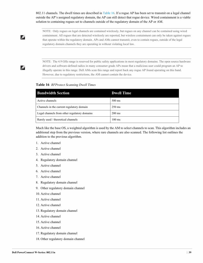
802.11 channels. The dwell times are described in Table 16. If a rogue AP has been set to transmit on a legal channel outside the AP’s assigned regulatory domain, the AP can still detect that rogue device. Wired containment is a viable solution to containing rogues set to channels outside of the regulatory domain of the AP or AM.
Much like the base OS, a weighted algorithm is used by the AM to select channels to scan. This algorithm includes an additional step from the previous version, where rare channels are also scanned. The following list outlines the addition to the previous algorithm.
1. Active channel
2. Active channel
3. Active channel
4. Regulatory domain channel
5. Active channel
6. Active channel
7. Active channel
8. Regulatory domain channel
9. Other regulatory domain channel
10. Active channel
11. Active channel
12. Active channel
13. Regulatory domain channel
14. Active channel
15. Active channel
16. Active channel
17. Regulatory domain channel
18. Other regulatory domain channel
NOTE: Only rogues on legal channels are contained wirelessly, but rogues on any channel can be contained using wired
containment. All rogues that are detected wirelessly are reported, but wireless containment can only be taken against rogues
that operate within the regulatory domain. APs and AMs cannot transmit, even to contain rogues, outside of the legal
regulatory domain channels they are operating in without violating local law.
NOTE: The 4.9 GHz range is reserved for public safety applications in most regulatory domains. The open source hardware
drivers and software-defined radios in many consumer grade APs mean that a malicious user could program an AP to
illegally operate in this range. Dell AMs scan this range and report back any rogue AP found operating on this band.
However, due to regulatory restrictions, the AM cannot contain the device.
Table 16 RFProtect Scanning Dwell Times
Bandwidth Section Dwell Time
Active channels 500 ms
Channels in the current regulatory domain 250 ms
Legal channels from other regulatory domains 200 ms
Rarely used / theoretical channels 100 ms
Dell PowerConnect W-Series: 802.11n | 39
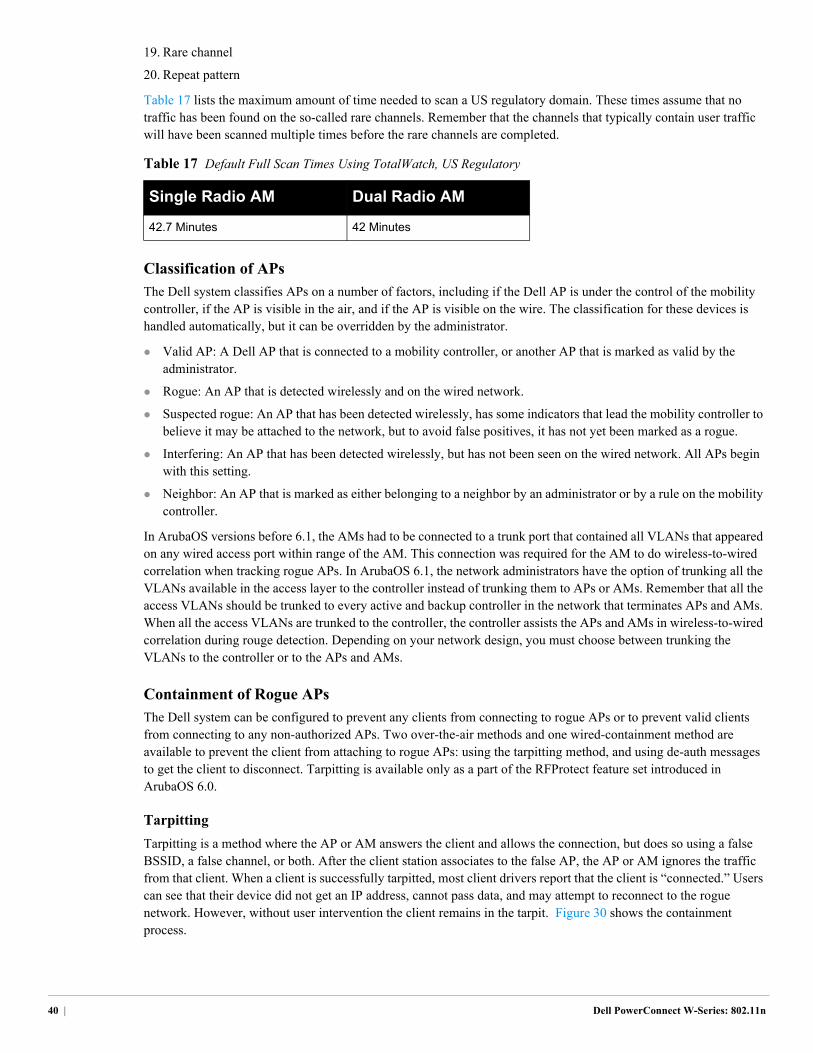
19. Rare channel
20. Repeat pattern
Table 17 lists the maximum amount of time needed to scan a US regulatory domain. These times assume that no traffic has been found on the so-called rare channels. Remember that the channels that typically contain user traffic will have been scanned multiple times before the rare channels are completed.
Classification of APs
The Dell system classifies APs on a number of factors, including if the Dell AP is under the control of the mobility controller, if the AP is visible in the air, and if the AP is visible on the wire. The classification for these devices is handled automatically, but it can be overridden by the administrator.
Valid AP: A Dell AP that is connected to a mobility controller, or another AP that is marked as valid by the administrator.
Rogue: An AP that is detected wirelessly and on the wired network.
Suspected rogue: An AP that has been detected wirelessly, has some indicators that lead the mobility controller to believe it may be attached to the network, but to avoid false positives, it has not yet been marked as a rogue.
Interfering: An AP that has been detected wirelessly, but has not been seen on the wired network. All APs begin with this setting.
Neighbor: An AP that is marked as either belonging to a neighbor by an administrator or by a rule on the mobility controller.
In ArubaOS versions before 6.1, the AMs had to be connected to a trunk port that contained all VLANs that appeared on any wired access port within range of the AM. This connection was required for the AM to do wireless-to-wired correlation when tracking rogue APs. In ArubaOS 6.1, the network administrators have the option of trunking all the VLANs available in the access layer to the controller instead of trunking them to APs or AMs. Remember that all the access VLANs should be trunked to every active and backup controller in the network that terminates APs and AMs. When all the access VLANs are trunked to the controller, the controller assists the APs and AMs in wireless-to-wired correlation during rouge detection. Depending on your network design, you must choose between trunking the VLANs to the controller or to the APs and AMs.
Containment of Rogue APs
The Dell system can be configured to prevent any clients from connecting to rogue APs or to prevent valid clients from connecting to any non-authorized APs. Two over-the-air methods and one wired-containment method are available to prevent the client from attaching to rogue APs: using the tarpitting method, and using de-auth messages to get the client to disconnect. Tarpitting is available only as a part of the RFProtect feature set introduced in ArubaOS 6.0.
Tarpitting
Tarpitting is a method where the AP or AM answers the client and allows the connection, but does so using a false BSSID, a false channel, or both. After the client station associates to the false AP, the AP or AM ignores the traffic from that client. When a client is successfully tarpitted, most client drivers report that the client is “connected.” Users can see that their device did not get an IP address, cannot pass data, and may attempt to reconnect to the rogue network. However, without user intervention the client remains in the tarpit. Figure 30 shows the containment process.
Table 17 Default Full Scan Times Using TotalWatch, US Regulatory
Single Radio AM Dual Radio AM
42.7 Minutes 42 Minutes
40 | Dell PowerConnect W-Series: 802.11n
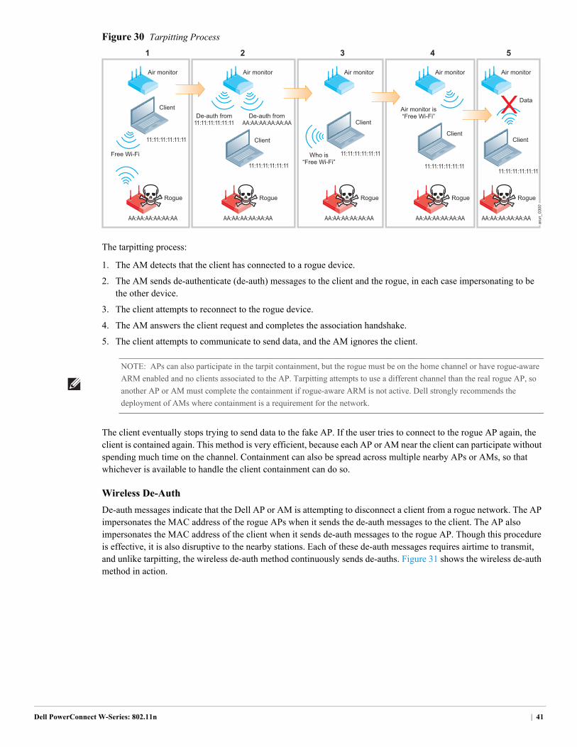
Figure 30 Tarpitting Process
The tarpitting process:
1. The AM detects that the client has connected to a rogue device.
2. The AM sends de-authenticate (de-auth) messages to the client and the rogue, in each case impersonating to be the other device.
3. The client attempts to reconnect to the rogue device.
4. The AM answers the client request and completes the association handshake.
5. The client attempts to communicate to send data, and the AM ignores the client.
The client eventually stops trying to send data to the fake AP. If the user tries to connect to the rogue AP again, the client is contained again. This method is very efficient, because each AP or AM near the client can participate without spending much time on the channel. Containment can also be spread across multiple nearby APs or AMs, so that whichever is available to handle the client containment can do so.
Wireless De-Auth
De-auth messages indicate that the Dell AP or AM is attempting to disconnect a client from a rogue network. The AP impersonates the MAC address of the rogue APs when it sends the de-auth messages to the client. The AP also impersonates the MAC address of the client when it sends de-auth messages to the rogue AP. Though this procedure is effective, it is also disruptive to the nearby stations. Each of these de-auth messages requires airtime to transmit, and unlike tarpitting, the wireless de-auth method continuously sends de-auths. Figure 31 shows the wireless de-auth method in action.
arun_0300
Air monitor is“Free Wi-Fi”
Air monitor
Rogue
Client
AA:AA:AA:AA:AA:AA
11:11:11:11:11:11Who is“Free Wi-Fi”
Air monitor
Rogue
Client
AA:AA:AA:AA:AA:AA
11:11:11:11:11:11
Air monitor
Rogue
Client
AA:AA:AA:AA:AA:AA
11:11:11:11:11:11
Air monitor
Rogue
Client
AA:AA:AA:AA:AA:AA
11:11:11:11:11:11
Data
De-auth fromAA:AA:AA:AA:AA:AA
De-auth from11:11:11:11:11:11
Air monitor
1 3 4 52
Rogue
Client
AA:AA:AA:AA:AA:AA
11:11:11:11:11:11
Free Wi-Fi
NOTE: APs can also participate in the tarpit containment, but the rogue must be on the home channel or have rogue-aware
ARM enabled and no clients associated to the AP. Tarpitting attempts to use a different channel than the real rogue AP, so
another AP or AM must complete the containment if rogue-aware ARM is not active. Dell strongly recommends the
deployment of AMs where containment is a requirement for the network.
Dell PowerConnect W-Series: 802.11n | 41
Figure 31 Using a de-auth denial of service to prevent a valid station from connecting to a rogue AP
In addition, unless an AM is present, the AP deauthenticates only rogue APs that are on its home channel. The primary goal of the AP is to serve clients. The only options to provide consistent containment of rogues is to deploy AMs or to enable rogue-aware ARM scanning, with the understanding that some client disruptions will occur. Dell recommends AM deployments in all networks if containment is needed.
Wired Containment
Wired containment works using ARP cache poisoning for each IP address rogue device (rogue AP or station) at the rate of one per second. Specifically, an ARP request is sent by the AM for the default gateway of the rogue device from the IP address being contained. An ARP response is also sent on behalf of the default gateway. All spoofed MAC addresses are locally administered so that the traffic is dropped. This exchange attempts to fool the device being contained and the default gateway.
If the Dell AM is on a trunk, the AM can transmit on multiple VLANs. As a result if the rogue is on a different VLAN from the Dell AP’s native VLAN, it can still contain the device. For a Layer 3 rogue AP, the Dell AP will ARP poison the MAC address, which is offset by 1 from the BSSID of the rogue.
Infrastructure IDS
For the network to function as intended, attacks on the infrastructure must be detected and mitigated. Dell considers that the infrastructure consists of authorized APs, the RF medium itself, and the wired network that the APs attach through. Unlike traditional wireless overlay security systems, the Dell system already knows which APs are authorized, because the RFProtect and the APs run from the same controller. The Dell system detects and protects against a large number of attacks that are aimed at disrupting the infrastructure system. For a complete list of attacks, see the ArubaOS User Guide. In addition to detecting attacks, the RFProtect module also provides different protection policies to contain offending unauthorized devices like rogue APs, misconfigured APs, and devices that use authorized SSIDs.
Client IDS
The Dell system must also monitor the clients that attach to the network. Any client that associates to the network, passes authentication, and is using encryption is considered a valid station. The system looks for various attack signatures, such as hotspotter and TKIP replay attacks that are targeted at clients that are attached to the wireless network. The system can also watch for valid stations that attempt to attach to rogue or neighbor APs. In addition to detecting attacks, the RFProtect module also provides different protection policies to contain misbehaving client devices. When “protect valid stations” is enabled in ArubaOS, the system uses the containment methods mentioned previously to prevent valid stations from attaching to any non-valid APs. For a complete list of client-side IDS signatures, see the Dell PowerConnect W-Series ArubaOS User Guide.
arun_0303
Client
AA:AA:AA:AA:AA:AA
De-auth fromAA:AA:AA:AA:AA:AA
11:11:11:11:11:11
De-auth from11:11:11:11:11:11
42 | Dell PowerConnect W-Series: 802.11n
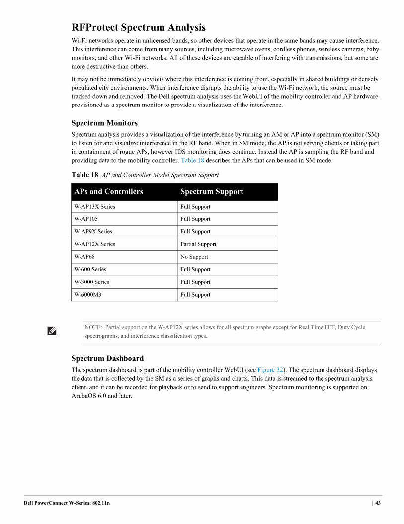
RFProtect Spectrum AnalysisWi-Fi networks operate in unlicensed bands, so other devices that operate in the same bands may cause interference. This interference can come from many sources, including microwave ovens, cordless phones, wireless cameras, baby monitors, and other Wi-Fi networks. All of these devices are capable of interfering with transmissions, but some are more destructive than others.
It may not be immediately obvious where this interference is coming from, especially in shared buildings or densely populated city environments. When interference disrupts the ability to use the Wi-Fi network, the source must be tracked down and removed. The Dell spectrum analysis uses the WebUI of the mobility controller and AP hardware provisioned as a spectrum monitor to provide a visualization of the interference.
Spectrum Monitors
Spectrum analysis provides a visualization of the interference by turning an AM or AP into a spectrum monitor (SM) to listen for and visualize interference in the RF band. When in SM mode, the AP is not serving clients or taking part in containment of rogue APs, however IDS monitoring does continue. Instead the AP is sampling the RF band and providing data to the mobility controller. Table 18 describes the APs that can be used in SM mode.
Spectrum Dashboard
The spectrum dashboard is part of the mobility controller WebUI (see Figure 32). The spectrum dashboard displays the data that is collected by the SM as a series of graphs and charts. This data is streamed to the spectrum analysis client, and it can be recorded for playback or to send to support engineers. Spectrum monitoring is supported on ArubaOS 6.0 and later.
Table 18 AP and Controller Model Spectrum Support
APs and Controllers Spectrum Support
W-AP13X Series Full Support
W-AP105 Full Support
W-AP9X Series Full Support
W-AP12X Series Partial Support
W-AP68 No Support
W-600 Series Full Support
W-3000 Series Full Support
W-6000M3 Full Support
NOTE: Partial support on the W-AP12X series allows for all spectrum graphs except for Real Time FFT, Duty Cycle
spectrographs, and interference classification types.
Dell PowerConnect W-Series: 802.11n | 43
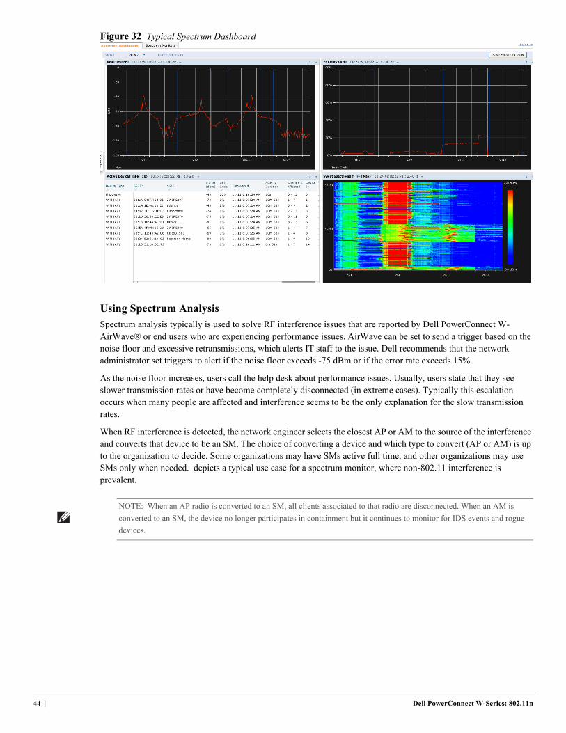
Figure 32 Typical Spectrum Dashboard
Using Spectrum Analysis
Spectrum analysis typically is used to solve RF interference issues that are reported by Dell PowerConnect W-AirWave® or end users who are experiencing performance issues. AirWave can be set to send a trigger based on the noise floor and excessive retransmissions, which alerts IT staff to the issue. Dell recommends that the network administrator set triggers to alert if the noise floor exceeds -75 dBm or if the error rate exceeds 15%.
As the noise floor increases, users call the help desk about performance issues. Usually, users state that they see slower transmission rates or have become completely disconnected (in extreme cases). Typically this escalation occurs when many people are affected and interference seems to be the only explanation for the slow transmission rates.
When RF interference is detected, the network engineer selects the closest AP or AM to the source of the interference and converts that device to be an SM. The choice of converting a device and which type to convert (AP or AM) is up to the organization to decide. Some organizations may have SMs active full time, and other organizations may use SMs only when needed. depicts a typical use case for a spectrum monitor, where non-802.11 interference is prevalent.
NOTE: When an AP radio is converted to an SM, all clients associated to that radio are disconnected. When an AM is
converted to an SM, the device no longer participates in containment but it continues to monitor for IDS events and rogue
devices.
44 | Dell PowerConnect W-Series: 802.11n
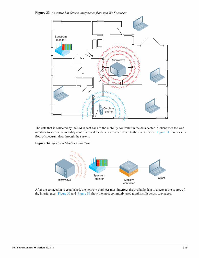
Figure 33 An active SM detects interference from non-Wi-Fi sources
The data that is collected by the SM is sent back to the mobility controller in the data center. A client uses the web interface to access the mobility controller, and the data is streamed down to the client device. Figure 34 describes the flow of spectrum data through the system.
Figure 34 Spectrum Monitor Data Flow
After the connection is established, the network engineer must interpret the available data to discover the source of the interference. Figure 35 and Figure 36 show the most commonly used graphs, split across two pages.
Microwave
Cordlessphone
Spectrummonitor
Mobilitycontroller
ClientSpectrummonitorMicrowave
Dell PowerConnect W-Series: 802.11n | 45
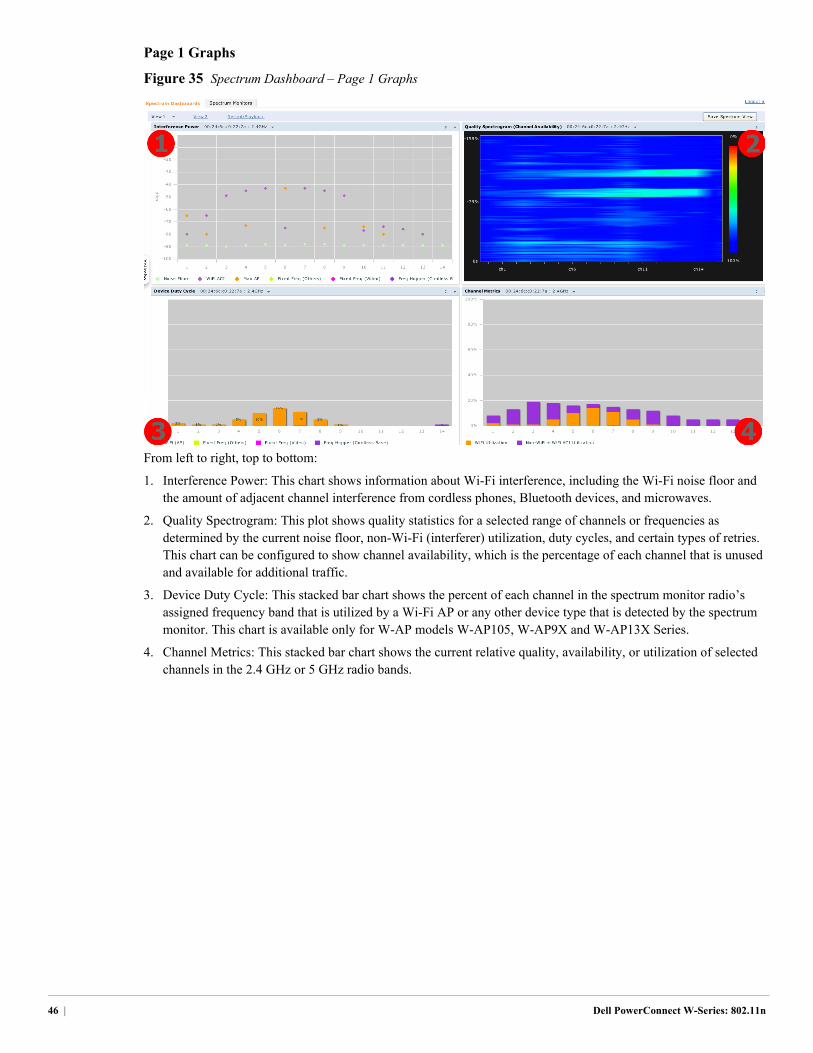
Page 1 Graphs
Figure 35 Spectrum Dashboard – Page 1 Graphs
From left to right, top to bottom:
1. Interference Power: This chart shows information about Wi-Fi interference, including the Wi-Fi noise floor and the amount of adjacent channel interference from cordless phones, Bluetooth devices, and microwaves.
2. Quality Spectrogram: This plot shows quality statistics for a selected range of channels or frequencies as determined by the current noise floor, non-Wi-Fi (interferer) utilization, duty cycles, and certain types of retries. This chart can be configured to show channel availability, which is the percentage of each channel that is unused and available for additional traffic.
3. Device Duty Cycle: This stacked bar chart shows the percent of each channel in the spectrum monitor radio’s assigned frequency band that is utilized by a Wi-Fi AP or any other device type that is detected by the spectrum monitor. This chart is available only for W-AP models W-AP105, W-AP9X and W-AP13X Series.
4. Channel Metrics: This stacked bar chart shows the current relative quality, availability, or utilization of selected channels in the 2.4 GHz or 5 GHz radio bands.
46 | Dell PowerConnect W-Series: 802.11n
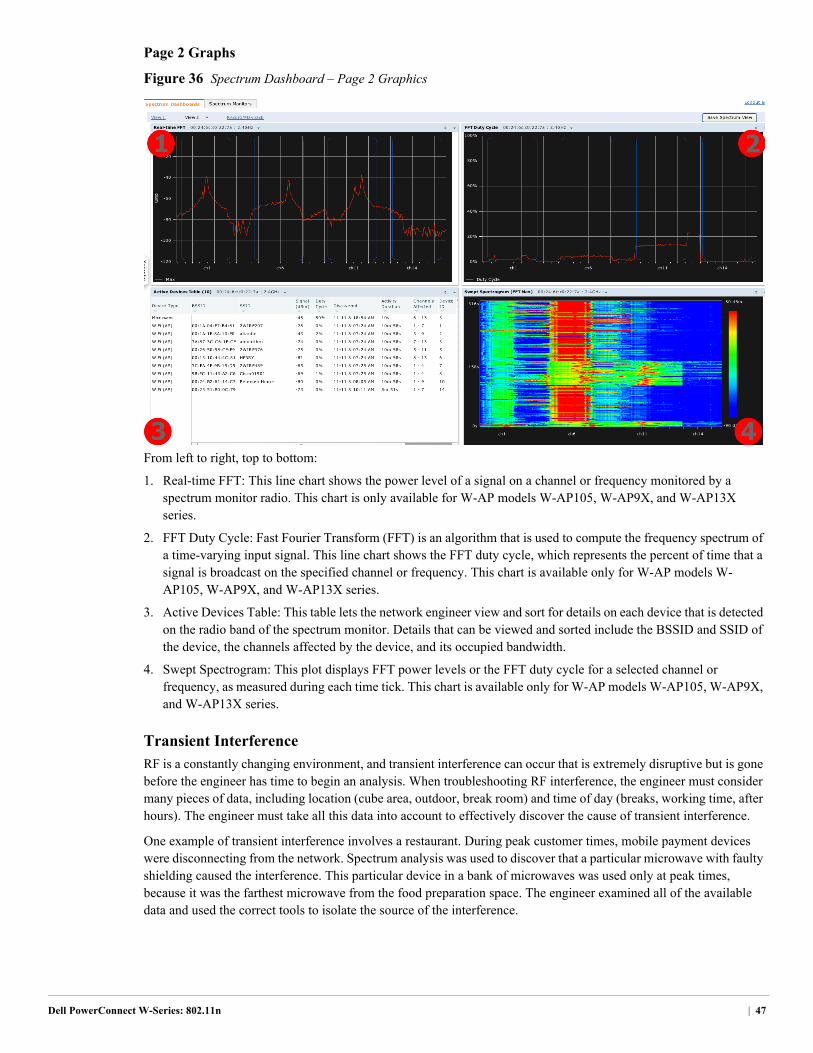
Page 2 Graphs
Figure 36 Spectrum Dashboard – Page 2 Graphics
From left to right, top to bottom:
1. Real-time FFT: This line chart shows the power level of a signal on a channel or frequency monitored by a spectrum monitor radio. This chart is only available for W-AP models W-AP105, W-AP9X, and W-AP13X series.
2. FFT Duty Cycle: Fast Fourier Transform (FFT) is an algorithm that is used to compute the frequency spectrum of a time-varying input signal. This line chart shows the FFT duty cycle, which represents the percent of time that a signal is broadcast on the specified channel or frequency. This chart is available only for W-AP models W-AP105, W-AP9X, and W-AP13X series.
3. Active Devices Table: This table lets the network engineer view and sort for details on each device that is detected on the radio band of the spectrum monitor. Details that can be viewed and sorted include the BSSID and SSID of the device, the channels affected by the device, and its occupied bandwidth.
4. Swept Spectrogram: This plot displays FFT power levels or the FFT duty cycle for a selected channel or frequency, as measured during each time tick. This chart is available only for W-AP models W-AP105, W-AP9X, and W-AP13X series.
Transient Interference
RF is a constantly changing environment, and transient interference can occur that is extremely disruptive but is gone before the engineer has time to begin an analysis. When troubleshooting RF interference, the engineer must consider many pieces of data, including location (cube area, outdoor, break room) and time of day (breaks, working time, after hours). The engineer must take all this data into account to effectively discover the cause of transient interference.
One example of transient interference involves a restaurant. During peak customer times, mobile payment devices were disconnecting from the network. Spectrum analysis was used to discover that a particular microwave with faulty shielding caused the interference. This particular device in a bank of microwaves was used only at peak times, because it was the farthest microwave from the food preparation space. The engineer examined all of the available data and used the correct tools to isolate the source of the interference.
Dell PowerConnect W-Series: 802.11n | 47
RFProtect RecommendationsRFProtect is a licensed software module that enables additional security and troubleshooting functionality on APs and the mobility controller. Dell recommends RFProtect for any organization that needs wireless IDS/IPS functionality. Organizations that are concerned about attacks and those subject to compliance reporting will benefit from the features that RFProtect provides. Examples of organizations that must report compliance are retailers under the payment card industry (PCI), and the healthcare industry for the health insurance portability and accountability act (HIPAA).
All organizations benefit from spectrum analysis when they troubleshoot wireless interference issues. Using RFProtect, Dell 802.11n APs can be put in to spectrum monitor mode for advanced troubleshooting. This capability provides an AP-level view of the interference and eliminates the need for a visit to the location for troubleshooting.
For most installations, the default RFProtect settings provide the appropriate level of alerts for most organizations. Dell recommends working with experienced RF security engineers and a legal advisor familiar with local laws to select the correct settings to meet the needs of the organization.
48 | Dell PowerConnect W-Series: 802.11n
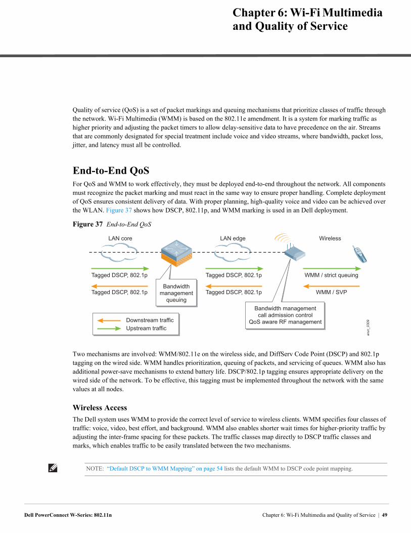
Dell PowerConnect W-Series: 802.11n
Chapter 6: Wi-Fi Multimedia and Quality of Service
Quality of service (QoS) is a set of packet markings and queuing mechanisms that prioritize classes of traffic through the network. Wi-Fi Multimedia (WMM) is based on the 802.11e amendment. It is a system for marking traffic as higher priority and adjusting the packet timers to allow delay-sensitive data to have precedence on the air. Streams that are commonly designated for special treatment include voice and video streams, where bandwidth, packet loss, jitter, and latency must all be controlled.
End-to-End QoSFor QoS and WMM to work effectively, they must be deployed end-to-end throughout the network. All components must recognize the packet marking and must react in the same way to ensure proper handling. Complete deployment of QoS ensures consistent delivery of data. With proper planning, high-quality voice and video can be achieved over the WLAN. Figure 37 shows how DSCP, 802.11p, and WMM marking is used in an Dell deployment.
Figure 37 End-to-End QoS
Two mechanisms are involved: WMM/802.11e on the wireless side, and DiffServ Code Point (DSCP) and 802.1p tagging on the wired side. WMM handles prioritization, queuing of packets, and servicing of queues. WMM also has additional power-save mechanisms to extend battery life. DSCP/802.1p tagging ensures appropriate delivery on the wired side of the network. To be effective, this tagging must be implemented throughout the network with the same values at all nodes.
Wireless Access
The Dell system uses WMM to provide the correct level of service to wireless clients. WMM specifies four classes of traffic: voice, video, best effort, and background. WMM also enables shorter wait times for higher-priority traffic by adjusting the inter-frame spacing for these packets. The traffic classes map directly to DSCP traffic classes and marks, which enables traffic to be easily translated between the two mechanisms.
arun_0309
Bandwidth managementcall admission control
QoS aware RF management
Bandwidthmanagement
queuing
Tagged DSCP, 802.1p
Tagged DSCP, 802.1p
Downstream trafficUpstream traffic
Tagged DSCP, 802.1p
Tagged DSCP, 802.1p
WMM / strict queuing
WMM / SVP
LAN core LAN edge Wireless
NOTE: “Default DSCP to WMM Mapping” on page 54 lists the default WMM to DSCP code point mapping.
Chapter 6: Wi-Fi Multimedia and Quality of Service | 49
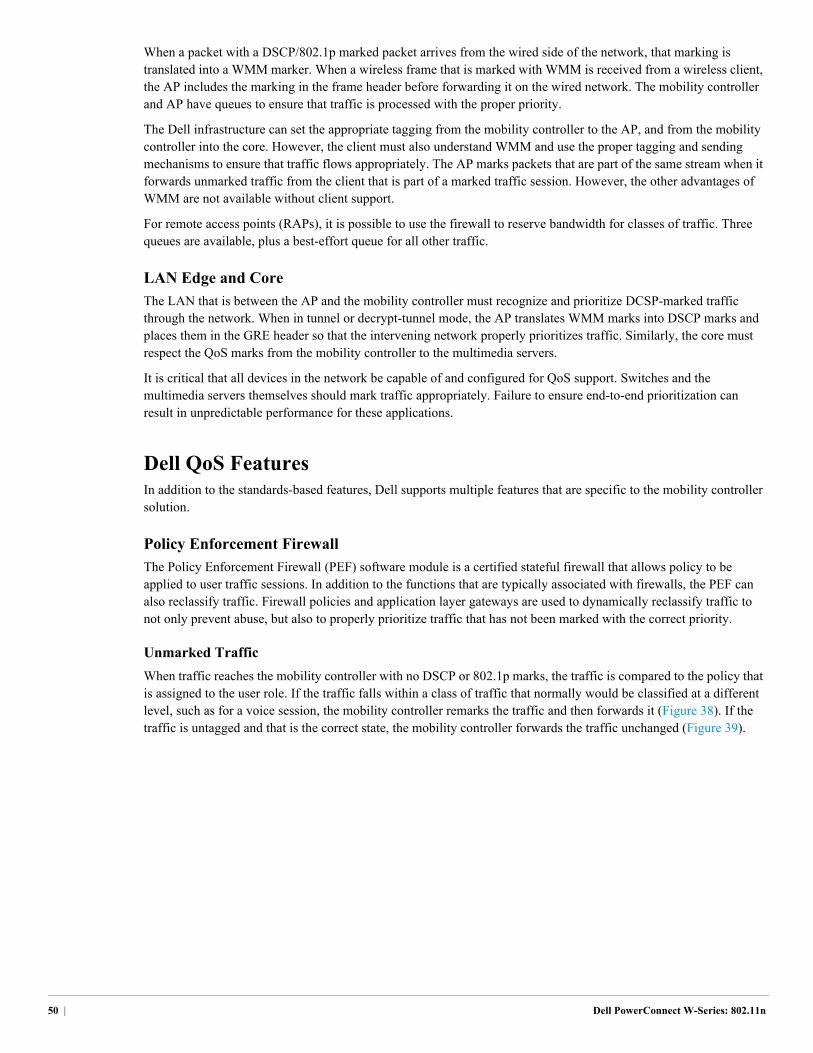
When a packet with a DSCP/802.1p marked packet arrives from the wired side of the network, that marking is translated into a WMM marker. When a wireless frame that is marked with WMM is received from a wireless client, the AP includes the marking in the frame header before forwarding it on the wired network. The mobility controller and AP have queues to ensure that traffic is processed with the proper priority.
The Dell infrastructure can set the appropriate tagging from the mobility controller to the AP, and from the mobility controller into the core. However, the client must also understand WMM and use the proper tagging and sending mechanisms to ensure that traffic flows appropriately. The AP marks packets that are part of the same stream when it forwards unmarked traffic from the client that is part of a marked traffic session. However, the other advantages of WMM are not available without client support.
For remote access points (RAPs), it is possible to use the firewall to reserve bandwidth for classes of traffic. Three queues are available, plus a best-effort queue for all other traffic.
LAN Edge and Core
The LAN that is between the AP and the mobility controller must recognize and prioritize DCSP-marked traffic through the network. When in tunnel or decrypt-tunnel mode, the AP translates WMM marks into DSCP marks and places them in the GRE header so that the intervening network properly prioritizes traffic. Similarly, the core must respect the QoS marks from the mobility controller to the multimedia servers.
It is critical that all devices in the network be capable of and configured for QoS support. Switches and the multimedia servers themselves should mark traffic appropriately. Failure to ensure end-to-end prioritization can result in unpredictable performance for these applications.
Dell QoS FeaturesIn addition to the standards-based features, Dell supports multiple features that are specific to the mobility controller solution.
Policy Enforcement Firewall
The Policy Enforcement Firewall (PEF) software module is a certified stateful firewall that allows policy to be applied to user traffic sessions. In addition to the functions that are typically associated with firewalls, the PEF can also reclassify traffic. Firewall policies and application layer gateways are used to dynamically reclassify traffic to not only prevent abuse, but also to properly prioritize traffic that has not been marked with the correct priority.
Unmarked Traffic
When traffic reaches the mobility controller with no DSCP or 802.1p marks, the traffic is compared to the policy that is assigned to the user role. If the traffic falls within a class of traffic that normally would be classified at a different level, such as for a voice session, the mobility controller remarks the traffic and then forwards it (Figure 38). If the traffic is untagged and that is the correct state, the mobility controller forwards the traffic unchanged (Figure 39).
50 | Dell PowerConnect W-Series: 802.11n
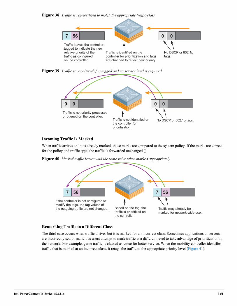
Figure 38 Traffic is reprioritized to match the appropriate traffic class
Figure 39 Traffic is not altered if untagged and no service level is required
Incoming Traffic Is Marked
When traffic arrives and it is already marked, those marks are compared to the system policy. If the marks are correct for the policy and traffic type, the traffic is forwarded unchanged ().
Figure 40 Marked traffic leaves with the same value when marked appropriately
Remarking Traffic to a Different Class
The third case occurs when traffic arrives but it is marked for an incorrect class. Sometimes applications or servers are incorrectly set, or malicious users attempt to mark traffic at a different level to take advantage of prioritization in the network. For example, game traffic is classed as voice for better service. When the mobility controller identifies traffic that is marked at an incorrect class, it retags the traffic to the appropriate priority level (Figure 41).
Traffic leaves the controllertagged to indicate the newrelative priority of thetraffic as configuredon the controller.
Traffic is identified on the controller for prioritization and tags are changed to reflect new priority.
No DSCP or 802.1ptags.
567 0 0
Traffic is not priority processedor queued on the controller.
0 0 0 0
Traffic is not identified onthe controller for prioritization.
No DSCP or 802.1p tags.
If the controller is not configured to modify the tags, the tag values ofthe outgoing traffic are not changed. Based on the tag, the
traffic is prioritized onthe controller.
Traffic may already bemarked for network-wide use.
567 567
Dell PowerConnect W-Series: 802.11n | 51
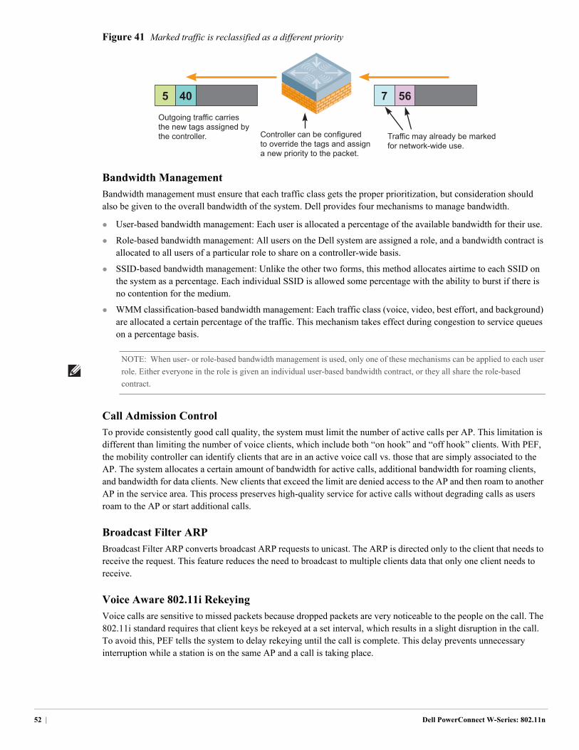
Figure 41 Marked traffic is reclassified as a different priority
Bandwidth Management
Bandwidth management must ensure that each traffic class gets the proper prioritization, but consideration should also be given to the overall bandwidth of the system. Dell provides four mechanisms to manage bandwidth.
User-based bandwidth management: Each user is allocated a percentage of the available bandwidth for their use.
Role-based bandwidth management: All users on the Dell system are assigned a role, and a bandwidth contract is allocated to all users of a particular role to share on a controller-wide basis.
SSID-based bandwidth management: Unlike the other two forms, this method allocates airtime to each SSID on the system as a percentage. Each individual SSID is allowed some percentage with the ability to burst if there is no contention for the medium.
WMM classification-based bandwidth management: Each traffic class (voice, video, best effort, and background) are allocated a certain percentage of the traffic. This mechanism takes effect during congestion to service queues on a percentage basis.
Call Admission Control
To provide consistently good call quality, the system must limit the number of active calls per AP. This limitation is different than limiting the number of voice clients, which include both “on hook” and “off hook” clients. With PEF, the mobility controller can identify clients that are in an active voice call vs. those that are simply associated to the AP. The system allocates a certain amount of bandwidth for active calls, additional bandwidth for roaming clients, and bandwidth for data clients. New clients that exceed the limit are denied access to the AP and then roam to another AP in the service area. This process preserves high-quality service for active calls without degrading calls as users roam to the AP or start additional calls.
Broadcast Filter ARP
Broadcast Filter ARP converts broadcast ARP requests to unicast. The ARP is directed only to the client that needs to receive the request. This feature reduces the need to broadcast to multiple clients data that only one client needs to receive.
Voice Aware 802.11i Rekeying
Voice calls are sensitive to missed packets because dropped packets are very noticeable to the people on the call. The 802.11i standard requires that client keys be rekeyed at a set interval, which results in a slight disruption in the call. To avoid this, PEF tells the system to delay rekeying until the call is complete. This delay prevents unnecessary interruption while a station is on the same AP and a call is taking place.
567405
Outgoing traffic carriesthe new tags assigned bythe controller. Controller can be configured
to override the tags and assigna new priority to the packet.
Traffic may already be markedfor network-wide use.
NOTE: When user- or role-based bandwidth management is used, only one of these mechanisms can be applied to each user
role. Either everyone in the role is given an individual user-based bandwidth contract, or they all share the role-based
contract.
52 | Dell PowerConnect W-Series: 802.11n
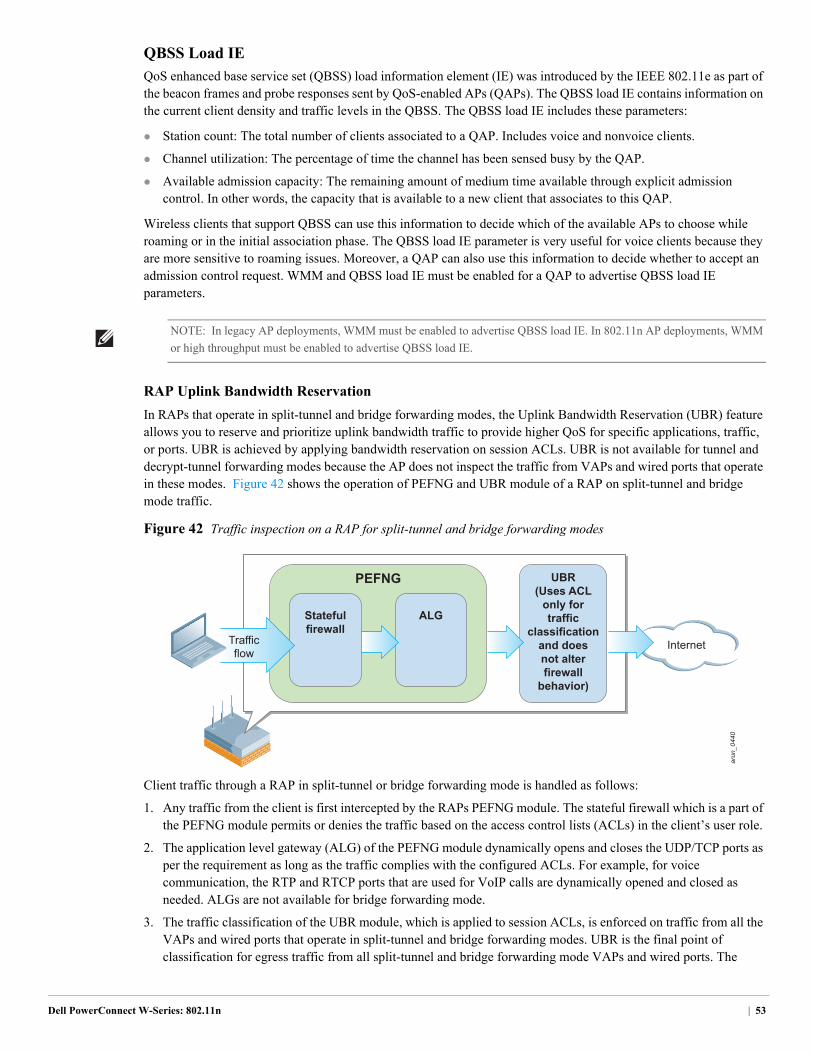
QBSS Load IE
QoS enhanced base service set (QBSS) load information element (IE) was introduced by the IEEE 802.11e as part of the beacon frames and probe responses sent by QoS-enabled APs (QAPs). The QBSS load IE contains information on the current client density and traffic levels in the QBSS. The QBSS load IE includes these parameters:
Station count: The total number of clients associated to a QAP. Includes voice and nonvoice clients.
Channel utilization: The percentage of time the channel has been sensed busy by the QAP.
Available admission capacity: The remaining amount of medium time available through explicit admission control. In other words, the capacity that is available to a new client that associates to this QAP.
Wireless clients that support QBSS can use this information to decide which of the available APs to choose while roaming or in the initial association phase. The QBSS load IE parameter is very useful for voice clients because they are more sensitive to roaming issues. Moreover, a QAP can also use this information to decide whether to accept an admission control request. WMM and QBSS load IE must be enabled for a QAP to advertise QBSS load IE parameters.
RAP Uplink Bandwidth Reservation
In RAPs that operate in split-tunnel and bridge forwarding modes, the Uplink Bandwidth Reservation (UBR) feature allows you to reserve and prioritize uplink bandwidth traffic to provide higher QoS for specific applications, traffic, or ports. UBR is achieved by applying bandwidth reservation on session ACLs. UBR is not available for tunnel and decrypt-tunnel forwarding modes because the AP does not inspect the traffic from VAPs and wired ports that operate in these modes. Figure 42 shows the operation of PEFNG and UBR module of a RAP on split-tunnel and bridge mode traffic.
Figure 42 Traffic inspection on a RAP for split-tunnel and bridge forwarding modes
Client traffic through a RAP in split-tunnel or bridge forwarding mode is handled as follows:
1. Any traffic from the client is first intercepted by the RAPs PEFNG module. The stateful firewall which is a part of the PEFNG module permits or denies the traffic based on the access control lists (ACLs) in the client’s user role.
2. The application level gateway (ALG) of the PEFNG module dynamically opens and closes the UDP/TCP ports as per the requirement as long as the traffic complies with the configured ACLs. For example, for voice communication, the RTP and RTCP ports that are used for VoIP calls are dynamically opened and closed as needed. ALGs are not available for bridge forwarding mode.
3. The traffic classification of the UBR module, which is applied to session ACLs, is enforced on traffic from all the VAPs and wired ports that operate in split-tunnel and bridge forwarding modes. UBR is the final point of classification for egress traffic from all split-tunnel and bridge forwarding mode VAPs and wired ports. The
NOTE: In legacy AP deployments, WMM must be enabled to advertise QBSS load IE. In 802.11n AP deployments, WMM
or high throughput must be enabled to advertise QBSS load IE.
arun_0440
PEFNG
Statefulfirewall
UBR(Uses ACL
only fortraffic
classificationand doesnot alterfirewall
behavior)
ALG
InternetTrafficflow
Dell PowerConnect W-Series: 802.11n | 53
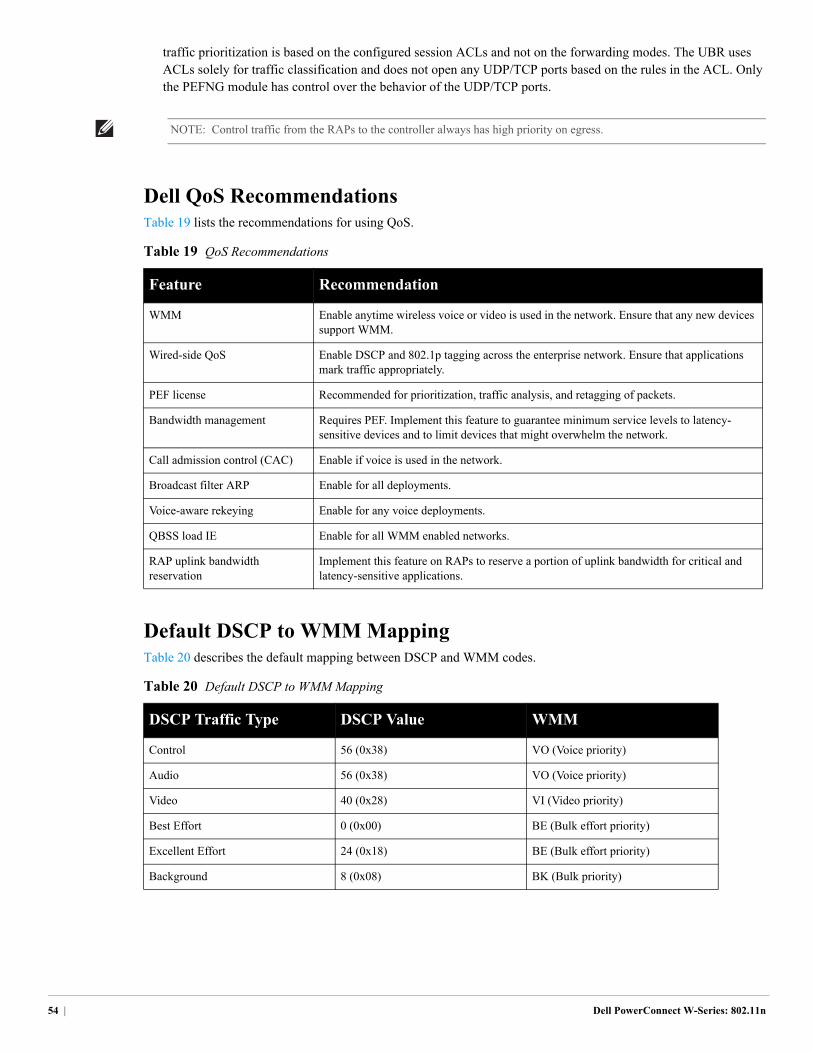
traffic prioritization is based on the configured session ACLs and not on the forwarding modes. The UBR uses ACLs solely for traffic classification and does not open any UDP/TCP ports based on the rules in the ACL. Only the PEFNG module has control over the behavior of the UDP/TCP ports.
Dell QoS RecommendationsTable 19 lists the recommendations for using QoS.
Default DSCP to WMM MappingTable 20 describes the default mapping between DSCP and WMM codes.
NOTE: Control traffic from the RAPs to the controller always has high priority on egress.
Table 19 QoS Recommendations
Feature Recommendation
WMM Enable anytime wireless voice or video is used in the network. Ensure that any new devices support WMM.
Wired-side QoS Enable DSCP and 802.1p tagging across the enterprise network. Ensure that applications mark traffic appropriately.
PEF license Recommended for prioritization, traffic analysis, and retagging of packets.
Bandwidth management Requires PEF. Implement this feature to guarantee minimum service levels to latency-sensitive devices and to limit devices that might overwhelm the network.
Call admission control (CAC) Enable if voice is used in the network.
Broadcast filter ARP Enable for all deployments.
Voice-aware rekeying Enable for any voice deployments.
QBSS load IE Enable for all WMM enabled networks.
RAP uplink bandwidth reservation
Implement this feature on RAPs to reserve a portion of uplink bandwidth for critical and latency-sensitive applications.
Table 20 Default DSCP to WMM Mapping
DSCP Traffic Type DSCP Value WMM
Control 56 (0x38) VO (Voice priority)
Audio 56 (0x38) VO (Voice priority)
Video 40 (0x28) VI (Video priority)
Best Effort 0 (0x00) BE (Bulk effort priority)
Excellent Effort 24 (0x18) BE (Bulk effort priority)
Background 8 (0x08) BK (Bulk priority)
54 | Dell PowerConnect W-Series: 802.11n
Dell PowerConnect W-Series: 802.11n
Chapter 7: Understanding Wireless Authentication and Encryption
A strong understanding of authentication and encryption is essential to deploy a secure and functional WLAN. Evaluate the different options against the goals of the organization and the security and operational requirements that the organization operates under. The number of different authentication and encryption options that must be supported also influences the design of the WLAN and the number of SSIDs that must be broadcast.
In general, each new authentication type or encryption mode that is required means that an additional SSID must be deployed. To preserve radio resources, organizations should consider the types of devices to be deployed and attempt to limit the number of SSIDs. Remember that each SSID that is deployed appears as an individual AP, and it must beacon, which uses up valuable airtime.
Authentication MethodsWi-Fi networks have multiple authentication methods available for use. Each method depends on the network goals, security requirements, user types, and client types that will access the network. Consider the types of data that will flow over the network, as that will narrow the authentication and encryption choices.
Authentication is typically separated into two models, Layer 2 and Layer 3. These models can be combined for additional authentication.
Layer 2 Authentication
Layer 2 authentication occurs before the client can complete a connection to the network and pass traffic. As the name suggests, the client does not have an IP address at this stage.
Open
Open authentication really means no authentication. The network is available for anyone to join and no keys are required. This form of authentication is often combined with a Layer 3 authentication method that is used after connection to the network.
WEP
Wired equivalent privacy (WEP) is the original security mechanism that was built into the 802.11 standard, and several variations are available. The most common version is static WEP where all stations share a single key for authentication and encryption. Other versions of WEP have different key lengths and dynamic key assignments.
As an authentication and encryption protocol, WEP was fully compromised in 2001. Automated tools make it easy to access a WEP network with no expertise or training. WEP is considered no more secure than an open network. Dell recommends that all organizations discontinue the use of WEP and replace any older WEP only devices with more capable systems as soon as is practical.
MAC Authentication
MAC authentication is an early form of filtering. MAC authentication requires that the MAC address of a machine must match a manually defined list of addresses. This form of authentication does not scale past a handful of devices, because it is difficult to maintain the list of MAC addresses. Additionally, it is easy to change the MAC address of a station to match one on the accepted list. This spoofing is trivial to perform with built-in driver tools, and it should not be relied upon to provide security.
MAC authentication can be used alone, but typically it is combined with other forms of authentication, such as WEP authentication. Because MAC addresses are easily observed during transmission and easily changed on the client, this
Chapter 7: Understanding Wireless Authentication and Encryption | 55
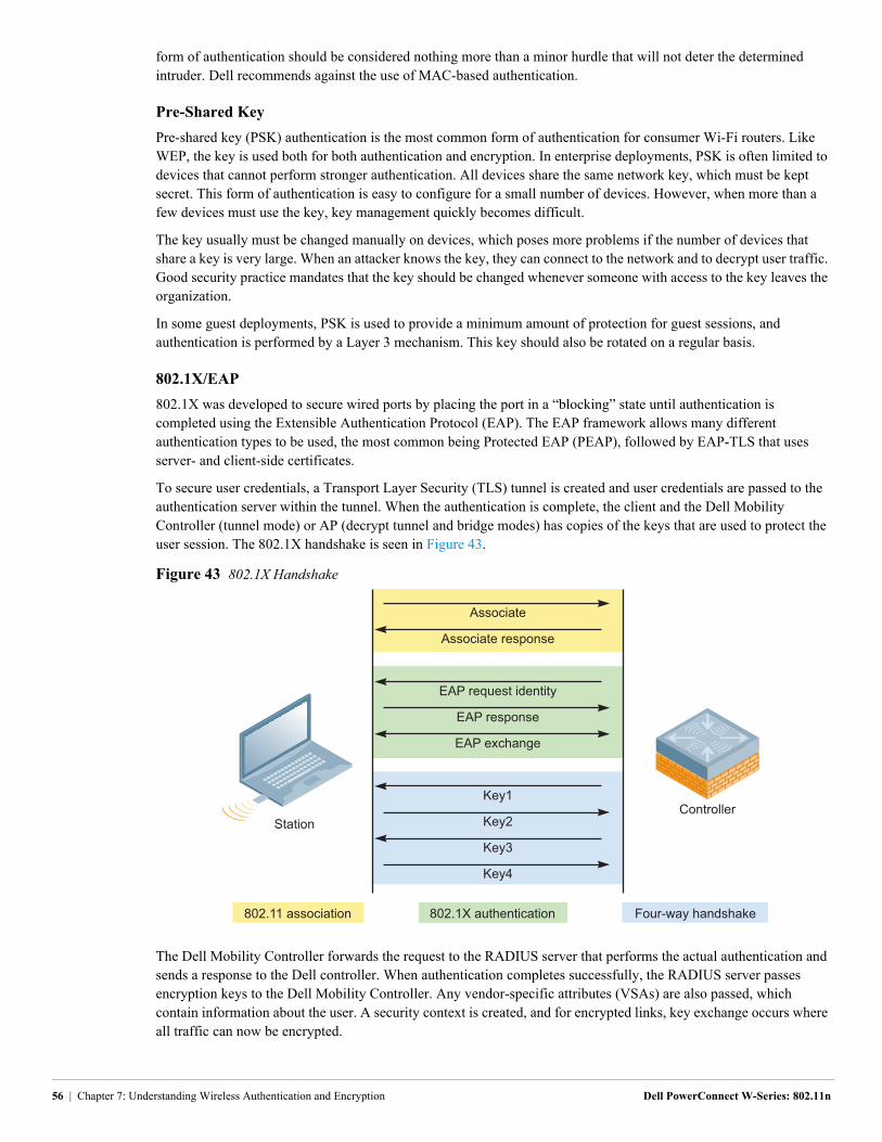
form of authentication should be considered nothing more than a minor hurdle that will not deter the determined intruder. Dell recommends against the use of MAC-based authentication.
Pre-Shared Key
Pre-shared key (PSK) authentication is the most common form of authentication for consumer Wi-Fi routers. Like WEP, the key is used both for both authentication and encryption. In enterprise deployments, PSK is often limited to devices that cannot perform stronger authentication. All devices share the same network key, which must be kept secret. This form of authentication is easy to configure for a small number of devices. However, when more than a few devices must use the key, key management quickly becomes difficult.
The key usually must be changed manually on devices, which poses more problems if the number of devices that share a key is very large. When an attacker knows the key, they can connect to the network and to decrypt user traffic. Good security practice mandates that the key should be changed whenever someone with access to the key leaves the organization.
In some guest deployments, PSK is used to provide a minimum amount of protection for guest sessions, and authentication is performed by a Layer 3 mechanism. This key should also be rotated on a regular basis.
802.1X/EAP
802.1X was developed to secure wired ports by placing the port in a “blocking” state until authentication is completed using the Extensible Authentication Protocol (EAP). The EAP framework allows many different authentication types to be used, the most common being Protected EAP (PEAP), followed by EAP-TLS that uses server- and client-side certificates.
To secure user credentials, a Transport Layer Security (TLS) tunnel is created and user credentials are passed to the authentication server within the tunnel. When the authentication is complete, the client and the Dell Mobility Controller (tunnel mode) or AP (decrypt tunnel and bridge modes) has copies of the keys that are used to protect the user session. The 802.1X handshake is seen in Figure 43.
Figure 43 802.1X Handshake
The Dell Mobility Controller forwards the request to the RADIUS server that performs the actual authentication and sends a response to the Dell controller. When authentication completes successfully, the RADIUS server passes encryption keys to the Dell Mobility Controller. Any vendor-specific attributes (VSAs) are also passed, which contain information about the user. A security context is created, and for encrypted links, key exchange occurs where all traffic can now be encrypted.
arun_057
Associate
Associate response
EAP request identity
EAP response
EAP exchange
ControllerStation
802.11 association 802.1X authentication Four-way handshake
Key1
Key2
Key3
Key4
56 | Chapter 7: Understanding Wireless Authentication and Encryption Dell PowerConnect W-Series: 802.11n
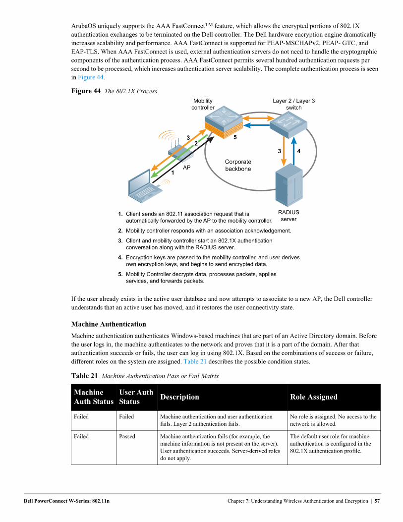
ArubaOS uniquely supports the AAA FastConnectTM feature, which allows the encrypted portions of 802.1X authentication exchanges to be terminated on the Dell controller. The Dell hardware encryption engine dramatically increases scalability and performance. AAA FastConnect is supported for PEAP-MSCHAPv2, PEAP- GTC, and EAP-TLS. When AAA FastConnect is used, external authentication servers do not need to handle the cryptographic components of the authentication process. AAA FastConnect permits several hundred authentication requests per second to be processed, which increases authentication server scalability. The complete authentication process is seen in Figure 44.
Figure 44 The 802.1X Process
If the user already exists in the active user database and now attempts to associate to a new AP, the Dell controller understands that an active user has moved, and it restores the user connectivity state.
Machine Authentication
Machine authentication authenticates Windows-based machines that are part of an Active Directory domain. Before the user logs in, the machine authenticates to the network and proves that it is a part of the domain. After that authentication succeeds or fails, the user can log in using 802.1X. Based on the combinations of success or failure, different roles on the system are assigned. Table 21 describes the possible condition states.
Table 21 Machine Authentication Pass or Fail Matrix
Machine Auth Status
User Auth Status
Description Role Assigned
Failed Failed Machine authentication and user authentication fails. Layer 2 authentication fails.
No role is assigned. No access to the network is allowed.
Failed Passed Machine authentication fails (for example, the machine information is not present on the server). User authentication succeeds. Server-derived roles do not apply.
The default user role for machine authentication is configured in the 802.1X authentication profile.
arun_056
Mobilitycontroller
1
5
3 4
3
AP
Layer 2 / Layer 3switch
Corporatebackbone
RADIUSserver
2
1.
2. 3.
4.
5.
Client sends an 802.11 association request that isautomatically forwarded by the AP to the mobility controller.
Mobility controller responds with an association acknowledgement.
Client and mobility controller start an 802.1X authenticationconversation along with the RADIUS server.
Encryption keys are passed to the mobility controller, and user derivesown encryption keys, and begins to send encrypted data.
Mobility Controller decrypts data, processes packets, appliesservices, and forwards packets.
Dell PowerConnect W-Series: 802.11n Chapter 7: Understanding Wireless Authentication and Encryption | 57
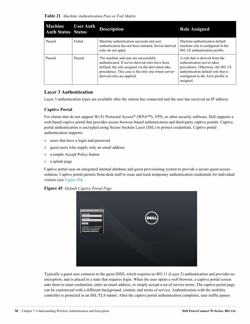
Layer 3 Authentication
Layer 3 authentication types are available after the station has connected and the user has received an IP address.
Captive Portal
For clients that do not support Wi-Fi Protected Access® (WPA™), VPN, or other security software, Dell supports a web-based captive portal that provides secure browser-based authentication and third-party captive portals. Captive portal authentication is encrypted using Secure Sockets Layer (SSL) to protect credentials. Captive portal authentication supports:
users that have a login and password
guest users who supply only an email address
a simple Accept Policy button
a splash page
Captive portal uses an integrated internal database and guest provisioning system to provide a secure guest access solution. Captive portal permits front-desk staff to issue and track temporary authentication credentials for individual visitors (see Figure 45).
Figure 45 Default Captive Portal Page
Typically a guest user connects to the guest SSID, which requires no 802.11 (Layer 2) authentication and provides no encryption, and is placed in a state that requires login. When the user opens a web browser, a captive portal screen asks them to enter credentials, enter an email address, or simply accept a set of service terms. The captive portal page can be customized with a different background, content, and terms of service. Authentication with the mobility controller is protected in an SSL/TLS tunnel. After the captive portal authentication completes, user traffic passes
Passed Failed Machine authentication succeeds and user authentication has not been initiated. Server-derived roles do not apply.
Machine authentication default machine role is configured in the 802.1X authentication profile.
Passed Passed The machine and user are successfully authenticated. If server-derived roles have been defined, the role assigned via the derivation take precedence. This case is the only one where server-derived roles are applied.
A role that is derived from the authentication server takes precedence. Otherwise, the 802.1X authentication default role that is configured in the AAA profile is assigned.
Table 21 Machine Authentication Pass or Fail Matrix
Machine Auth Status
User Auth Status
Description Role Assigned
58 | Chapter 7: Understanding Wireless Authentication and Encryption Dell PowerConnect W-Series: 802.11n
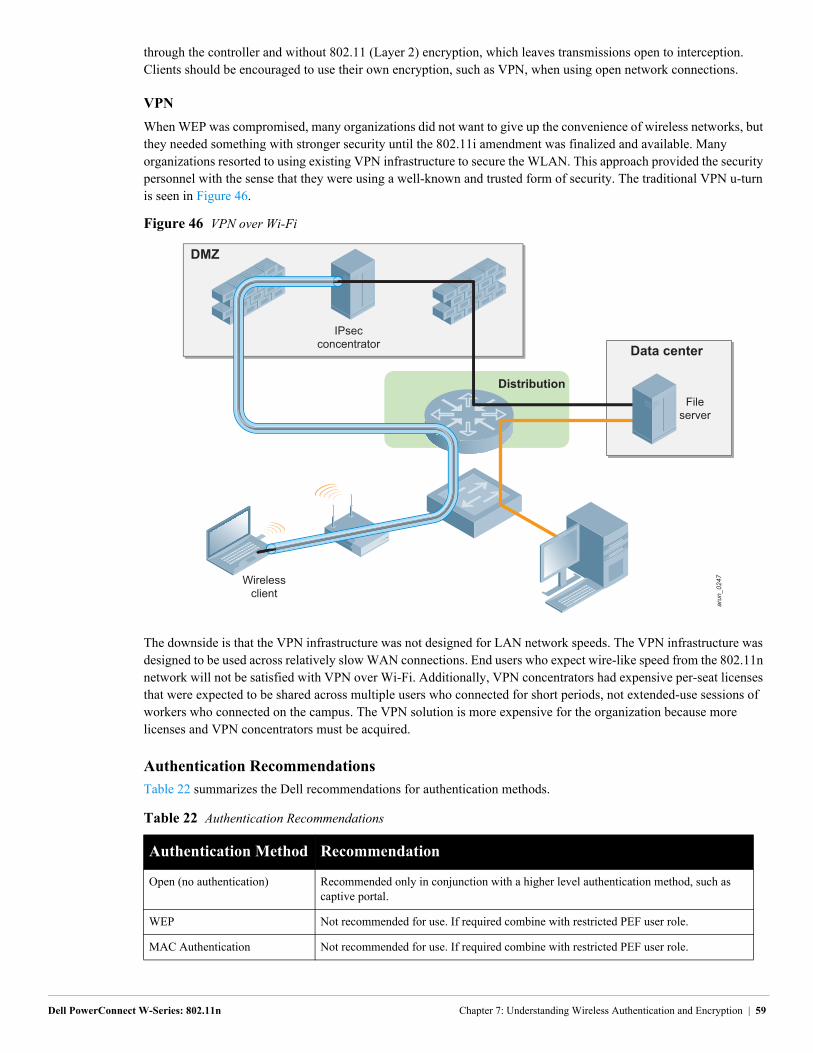
through the controller and without 802.11 (Layer 2) encryption, which leaves transmissions open to interception. Clients should be encouraged to use their own encryption, such as VPN, when using open network connections.
VPN
When WEP was compromised, many organizations did not want to give up the convenience of wireless networks, but they needed something with stronger security until the 802.11i amendment was finalized and available. Many organizations resorted to using existing VPN infrastructure to secure the WLAN. This approach provided the security personnel with the sense that they were using a well-known and trusted form of security. The traditional VPN u-turn is seen in Figure 46.
Figure 46 VPN over Wi-Fi
The downside is that the VPN infrastructure was not designed for LAN network speeds. The VPN infrastructure was designed to be used across relatively slow WAN connections. End users who expect wire-like speed from the 802.11n network will not be satisfied with VPN over Wi-Fi. Additionally, VPN concentrators had expensive per-seat licenses that were expected to be shared across multiple users who connected for short periods, not extended-use sessions of workers who connected on the campus. The VPN solution is more expensive for the organization because more licenses and VPN concentrators must be acquired.
Authentication Recommendations
Table 22 summarizes the Dell recommendations for authentication methods.
Table 22 Authentication Recommendations
Authentication Method Recommendation
Open (no authentication) Recommended only in conjunction with a higher level authentication method, such as captive portal.
WEP Not recommended for use. If required combine with restricted PEF user role.
MAC Authentication Not recommended for use. If required combine with restricted PEF user role.
arun_0247
Data center
DMZ
Distribution
IPsecconcentrator
Wirelessclient
Fileserver
Dell PowerConnect W-Series: 802.11n Chapter 7: Understanding Wireless Authentication and Encryption | 59
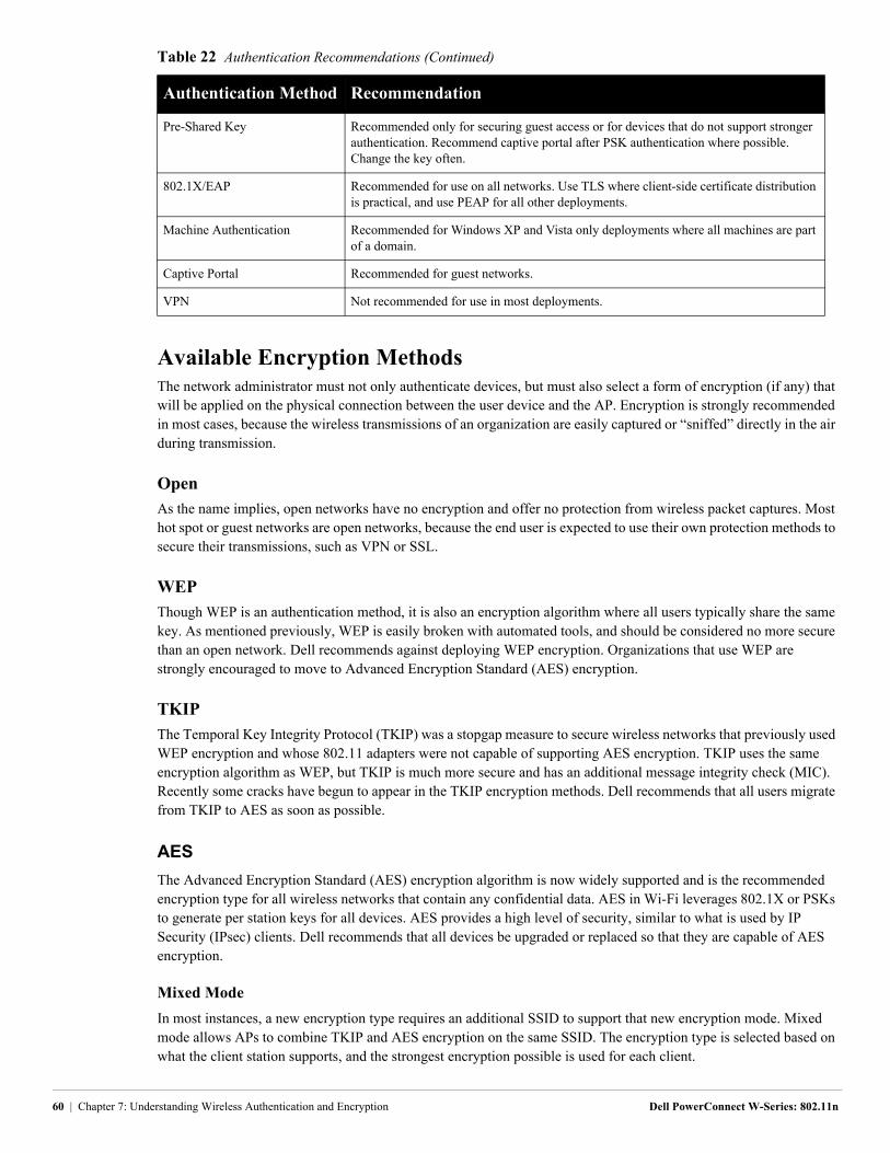
Available Encryption MethodsThe network administrator must not only authenticate devices, but must also select a form of encryption (if any) that will be applied on the physical connection between the user device and the AP. Encryption is strongly recommended in most cases, because the wireless transmissions of an organization are easily captured or “sniffed” directly in the air during transmission.
Open
As the name implies, open networks have no encryption and offer no protection from wireless packet captures. Most hot spot or guest networks are open networks, because the end user is expected to use their own protection methods to secure their transmissions, such as VPN or SSL.
WEP
Though WEP is an authentication method, it is also an encryption algorithm where all users typically share the same key. As mentioned previously, WEP is easily broken with automated tools, and should be considered no more secure than an open network. Dell recommends against deploying WEP encryption. Organizations that use WEP are strongly encouraged to move to Advanced Encryption Standard (AES) encryption.
TKIP
The Temporal Key Integrity Protocol (TKIP) was a stopgap measure to secure wireless networks that previously used WEP encryption and whose 802.11 adapters were not capable of supporting AES encryption. TKIP uses the same encryption algorithm as WEP, but TKIP is much more secure and has an additional message integrity check (MIC). Recently some cracks have begun to appear in the TKIP encryption methods. Dell recommends that all users migrate from TKIP to AES as soon as possible.
AES
The Advanced Encryption Standard (AES) encryption algorithm is now widely supported and is the recommended encryption type for all wireless networks that contain any confidential data. AES in Wi-Fi leverages 802.1X or PSKs to generate per station keys for all devices. AES provides a high level of security, similar to what is used by IP Security (IPsec) clients. Dell recommends that all devices be upgraded or replaced so that they are capable of AES encryption.
Mixed Mode
In most instances, a new encryption type requires an additional SSID to support that new encryption mode. Mixed mode allows APs to combine TKIP and AES encryption on the same SSID. The encryption type is selected based on what the client station supports, and the strongest encryption possible is used for each client.
Pre-Shared Key Recommended only for securing guest access or for devices that do not support stronger authentication. Recommend captive portal after PSK authentication where possible. Change the key often.
802.1X/EAP Recommended for use on all networks. Use TLS where client-side certificate distribution is practical, and use PEAP for all other deployments.
Machine Authentication Recommended for Windows XP and Vista only deployments where all machines are part of a domain.
Captive Portal Recommended for guest networks.
VPN Not recommended for use in most deployments.
Table 22 Authentication Recommendations (Continued)
Authentication Method Recommendation
60 | Chapter 7: Understanding Wireless Authentication and Encryption Dell PowerConnect W-Series: 802.11n
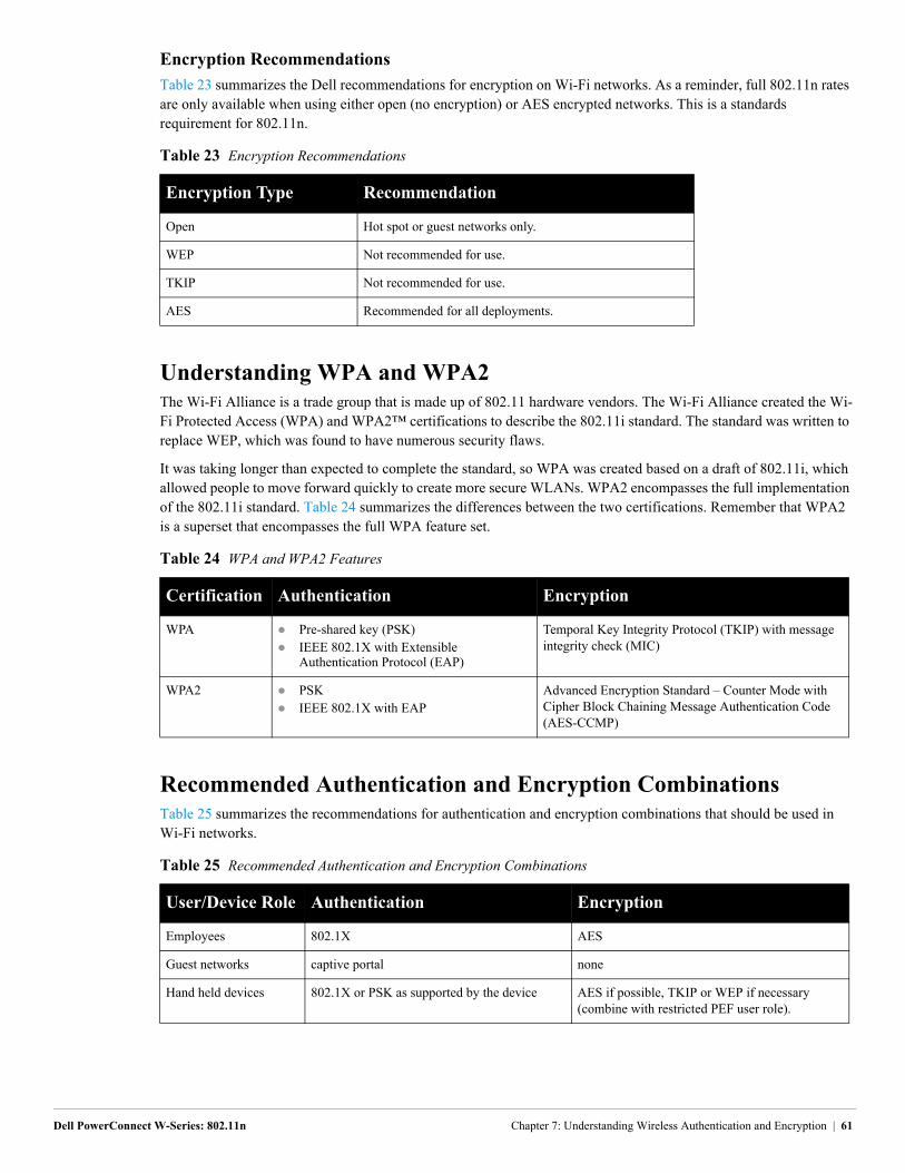
Encryption Recommendations
Table 23 summarizes the Dell recommendations for encryption on Wi-Fi networks. As a reminder, full 802.11n rates are only available when using either open (no encryption) or AES encrypted networks. This is a standards requirement for 802.11n.
Understanding WPA and WPA2The Wi-Fi Alliance is a trade group that is made up of 802.11 hardware vendors. The Wi-Fi Alliance created the Wi-Fi Protected Access (WPA) and WPA2™ certifications to describe the 802.11i standard. The standard was written to replace WEP, which was found to have numerous security flaws.
It was taking longer than expected to complete the standard, so WPA was created based on a draft of 802.11i, which allowed people to move forward quickly to create more secure WLANs. WPA2 encompasses the full implementation of the 802.11i standard. Table 24 summarizes the differences between the two certifications. Remember that WPA2 is a superset that encompasses the full WPA feature set.
Recommended Authentication and Encryption CombinationsTable 25 summarizes the recommendations for authentication and encryption combinations that should be used in Wi-Fi networks.
Table 23 Encryption Recommendations
Encryption Type Recommendation
Open Hot spot or guest networks only.
WEP Not recommended for use.
TKIP Not recommended for use.
AES Recommended for all deployments.
Table 24 WPA and WPA2 Features
Certification Authentication Encryption
WPA Pre-shared key (PSK) IEEE 802.1X with Extensible
Authentication Protocol (EAP)
Temporal Key Integrity Protocol (TKIP) with message integrity check (MIC)
WPA2 PSK IEEE 802.1X with EAP
Advanced Encryption Standard – Counter Mode with Cipher Block Chaining Message Authentication Code (AES-CCMP)
Table 25 Recommended Authentication and Encryption Combinations
User/Device Role Authentication Encryption
Employees 802.1X AES
Guest networks captive portal none
Hand held devices 802.1X or PSK as supported by the device AES if possible, TKIP or WEP if necessary (combine with restricted PEF user role).
Dell PowerConnect W-Series: 802.11n Chapter 7: Understanding Wireless Authentication and Encryption | 61

62 | Chapter 7: Understanding Wireless Authentication and Encryption Dell PowerConnect W-Series: 802.11n
Dell PowerConnect W-Series: 802.11n Chapter 8
Chapter 8: Understanding Configuration Profiles, AP Groups, and Virtual APs
Configuration profiles and AP groups work together to provide an abstraction layer between the physical settings of the system and the conceptual goals of the network architect. This abstraction feature provides the Dell administrator with the benefits of reusable groups of settings (called “profiles”) that can be applied in a mix-and-match fashion with extremely fine granularity.
Configuration ProfilesConfiguration profiles allow different aspects of the Dell system to be grouped into different configuration sets. Each profile is essentially a partial configuration. SSID profiles, radio profiles, and AAA profiles are just some of the available choices. Each profile includes parameters that can be adjusted to meet the needs of the design. Multiple versions of the same profile can be created and given different names. This flexibility allows the administrator to define a particular profile once and reuse it as needed, which reduces configuration errors and data entry.
The ArubaOS profile system is set up so that the configuration flow goes from high level to low level in a hierarchical manner. Unlike other hierarchical systems such as LDAP, the ArubaOS profile system does not provide arbitrary levels of depth or inheritance. The ability to copy a profile to create a new profile allows for rudimentary inheritance. Changes to the original profile are not reflected in the new profile.
To ease configuration, a set of startup and reusable wizards are available. The administrator answers basic questions about the WLAN configuration, and the wizard creates the necessary profiles to setup the WLAN.
Profile Types
The basic idea of a profile is very straightforward. With 65 different profiles available, ArubaOS 6.0 offers the administrator almost unlimited control over how their wireless network can be implemented. The main categories of profiles are shown in Figure 47. Each box represents a different profile, and certain profiles are nested within others.
: Understanding Configuration Profiles, AP Groups, and Virtual APs | 63
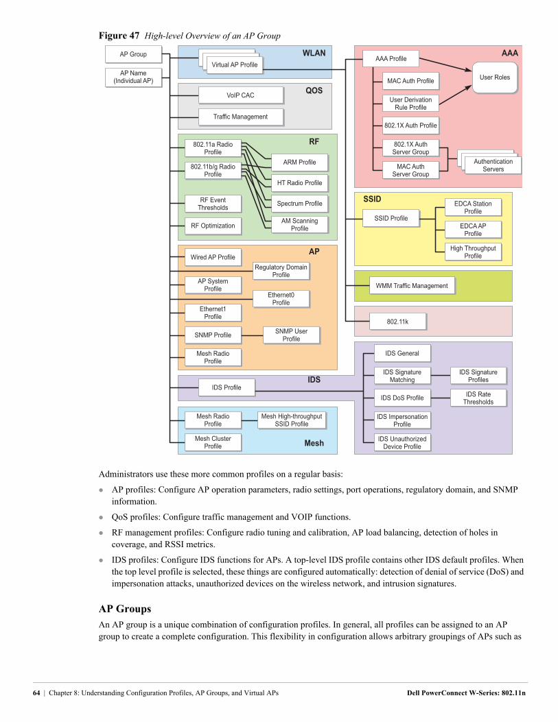
Figure 47 High-level Overview of an AP Group
Administrators use these more common profiles on a regular basis:
AP profiles: Configure AP operation parameters, radio settings, port operations, regulatory domain, and SNMP information.
QoS profiles: Configure traffic management and VOIP functions.
RF management profiles: Configure radio tuning and calibration, AP load balancing, detection of holes in coverage, and RSSI metrics.
IDS profiles: Configure IDS functions for APs. A top-level IDS profile contains other IDS default profiles. When the top level profile is selected, these things are configured automatically: detection of denial of service (DoS) and impersonation attacks, unauthorized devices on the wireless network, and intrusion signatures.
AP Groups
An AP group is a unique combination of configuration profiles. In general, all profiles can be assigned to an AP group to create a complete configuration. This flexibility in configuration allows arbitrary groupings of APs such as
IDS Profile
IDS UnauthorizedDevice Profile
IDS DoS Profile
IDS SignatureMatching
IDS RateThresholds
IDS SignatureProfiles
IDS General
AP Name(Individual AP)
AP Group WLAN
QOS
AAA
IDS
IDS ImpersonationProfile
User Roles
User DerivationRule Profile
802.1X Auth Profile
MAC AuthServer Group
MAC Auth Profile
802.1X AuthServer Group
AAA Profile
SSID
Mesh
SSID ProfileEDCA AP
Profile
EDCA StationProfile
High ThroughputProfile
VoIP CAC
Virtual AP Profile
AuthenticationServers
Traffic Management
802.11k
WMM Traffic Management
RF
RF Optimization
RF EventThresholds
802.11a RadioProfile
802.11b/g RadioProfile
ARM Profile
HT Radio Profile
Spectrum Profile
AM ScanningProfile
Mesh RadioProfile
AP
Ethernet1Profile
AP SystemProfile
Wired AP Profile
SNMP Profile SNMP UserProfile
Mesh ClusterProfile
Mesh RadioProfile
Mesh High-throughputSSID Profile
Regulatory DomainProfile
Ethernet0Profile
64 | Chapter 8: Understanding Configuration Profiles, AP Groups, and Virtual APs Dell PowerConnect W-Series: 802.11n
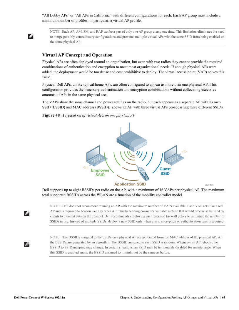
“All Lobby APs” or “All APs in California” with different configurations for each. Each AP group must include a minimum number of profiles, in particular, a virtual AP profile.
Virtual AP Concept and Operation
Physical APs are often deployed around an organization, but even with two radios they cannot provide the required combinations of authentication and encryption to meet most organizational needs. If enough physical APs were added, the deployment would be too dense and cost prohibitive to deploy. The virtual access point (VAP) solves this issue.
Physical Dell APs, unlike typical home APs, are often configured to appear as more than one physical AP. This configuration provides the necessary authentication and encryption combinations without collocating excessive amounts of APs in the same physical area.
The VAPs share the same channel and power settings on the radio, but each appears as a separate AP with its own SSID (ESSID) and MAC address (BSSID). shows an AP with three virtual APs broadcasting three different SSIDs.
Figure 48 A typical set of virtual APs on one physical AP
Dell supports up to eight BSSIDs per radio on the AP, with a maximum of 16 VAPs per physical AP. The maximum total supported BSSIDs across the WLAN are a function of the mobility controller model.
NOTE: Each AP, AM, SM, and RAP can be a part of only one AP group at any one time. This limitation eliminates the need
to merge possibly contradictory configurations and prevents multiple virtual APs with the same SSID from being enabled on
the same physical AP.
arun_055
EmployeeSSID
Application SSID
GuestSSID
NOTE: Dell does not recommend running an AP with the maximum number of VAPs available. Each VAP acts like a real
AP and is required to beacon like any other AP. This beaconing consumes valuable airtime that would otherwise be used by
clients to transmit data on the channel. Dell recommends employing user roles and firewall policy to minimize the number of
SSIDs in use. Instead of multiple SSIDs, deploy a new SSID only when a new encryption or authentication type is required.
NOTE: The BSSIDs assigned to the SSIDs on a physical AP are generated from the MAC address of the physical AP. All
the BSSIDs are generated by an algorithm. The BSSID assigned to each SSID is random. Whenever an AP reboots, the
BSSID to SSID mapping may change. In certain situations, an SSID may be temporarily disabled for maintenance. When
this SSID is enabled again, the BSSID assigned to it might not be the same as before.
Dell PowerConnect W-Series: 802.11n Chapter 8: Understanding Configuration Profiles, AP Groups, and Virtual APs | 65
SSIDs, Encryption, and Authentication
As mentioned previously, a new SSID is required each time a new encryption or authentication type is required, which drives the creation of an additional VAP. This situation has the following limitations:
Two VAPs in the same AP group cannot share the same SSID. Clients could easily be confused and it does not make sense to have the same SSID broadcast multiple times from the same AP on the same band.
The number of VAPs cannot exceed the capabilities of the APs to which the group is assigned.
Radio Settings
A number of radio settings affect how the WLAN functions. Some of the key functions are described here:
ARM: All the ARM settings are available within the AP group, which allows administrators to tune the network to match the environment, from typical campus settings to warehouses.
Data rates: In some instances, it is useful to eliminate lower data rates to force clients to find a more attractive AP, such as in a dense stadium deployment.
Country codes: Certain features of the 802.11n standard (and even 802.11n itself) are not allowed to be used in all countries. In addition, channel and power limits vary by location. The country code on the controller allows Dell to control what features of the specification, power, and channel are usable in each location. As the regulations change and more features are allowed, the software can be updated to enable these features.
WMM
Wi-Fi Multimedia (WMM) is a certification program that was created by the Wi-Fi Alliance that covers QoS over Wi-Fi networks. WMM prioritizes traffic into one of four queues, and traffic receives different treatment in the network based on its traffic class. The different treatment includes a shortened wait time between packets and wired-side tagging of packets using DSCP and 802.1p marks. Dell allows users to define which traffic fits in to each queue. Also, DSCP and 802.1p marks can be adjusted appropriately to match the network.
LMS and Backup LMS
The Dell system has a concept of a local management switch (LMS) and a backup LMS. These terms are older terms that survive in the configuration; an LMS is a local mobility controller. In a typical deployment, the AP contacts the master mobility controller and is directed to the mobility controller that handles the AP connection and traffic via the LMS parameter. This controller is typically a local controller, but it can also be the master in smaller networks. If the LMS becomes unreachable and a backup LMS is specified, the AP attempts to reconnect to that backup mobility controller. This function provides Layer 3 and site redundancy when this level of redundancy is required.
Designing VAPs to Meet Organizational Needs
Some planning is needed to use the profile system effectively. Unlike most planning decisions in network designs, profile planning is not based on performance and scalability. Profile planning is based on creating a functional and flexible network design that can be logically understood. Ideally, this planning is part of the network planning.
Though it is possible simply to place all of the equipment in default profiles and change the parameters to suit the needs of the organization, the full power and flexibility of the system will not be available. To take full advantage of the system, the network administrator must consider the physical layout of the equipment, the technical management requirements, and the business practices and regulatory requirements that are specific to the organization.
The Dell controllers that run earlier versions of ArubaOS have a predefined AP group named default. When an AP boots up and finds a controller, it is automatically placed in the default AP group. This AP group has a default VAP and SSID that have open authentication by default. The AP now broadcasts the default SSID to which clients can connect. Dell recommends that network administrators change the following defaults:
default ap-group
default virtual-ap
default ssid
66 | Chapter 8: Understanding Configuration Profiles, AP Groups, and Virtual APs Dell PowerConnect W-Series: 802.11n

Dell recommends that network administrators change the default AP group for new APs to AM mode and create a new AP group with the specific SSIDs and related configuration to be used for the organization. When the default is set to AM mode, anyone who plugs an unauthorized Dell AP into the network simply adds to the monitoring capacity and does not create a potential security vulnerability.
In ArubaOS 6.1, the default SSID has been removed from the default AP group. So an AP that is automatically placed in the default AP group by a Dell controller running ArubaOS 6.1 will not broadcast any SSID.
NOTE: The default SSID profile should not be used in a Dell deployment. Network administrators are encouraged to make
the default profile an AM profile to help protect their network from “gray market” APs that users may attempt to connect to
the WLAN.
Dell PowerConnect W-Series: 802.11n Chapter 8: Understanding Configuration Profiles, AP Groups, and Virtual APs | 67

68 | Chapter 8: Understanding Configuration Profiles, AP Groups, and Virtual APs Dell PowerConnect W-Series: 802.11n
Dell PowerConnect W-Series: 802.11n
Chapter 9: Dell PowerConnect W-Series APs
Dell offers multiple 802.11n APs and antennas to meet a wide range of deployment needs. This chapter describes the process to select the proper AP and antenna combination to meet the deployment requirements for the WLAN. For detailed information on the range of Dell APs and antennas, see the PowerConnect W-Series Antenna Line Matrix at http://www.dell.com/wireless.
AP Feature SelectionThe range of Dell APs offers a number of different features on the AP hardware itself, including the number of radios, ports, and internal or external antennas. Each of these options is explained here.
Single- and Dual-Radio AP Models
Each AP has one or two radios. On single-radio models (except the RAP-2WG and AP-68 series APs), the radio can be set to either 2.4 GHz or 5 GHz. When single-radio models are provisioned as an AM, both bands are scanned. With a dual-radio AP, each radio is locked on one of the bands. When a single-radio AP is deployed, the AP talks to clients only on a single band, which limits the number of clients that can connect to the AP. When an AP is provisioned to use the 5 GHz band, the AP is invisible to clients that are capable only of 2.4 GHz operation, such as phones and scanner guns.
Dual-radio APs allow for full use of the available spectrum. When band steering is used, dual-radio APs allow clients to be spread across the two bands, which increases throughput by moving clients to less congested bands. Band steering leads to more efficient use of the available spectrum and client connectivity, as well as making available the maximum BSSID count per AP as mentioned previously.
Internal Antenna vs. External Antenna
Most Dell APs come in two models, those with internal omnidirectional antennas and those with external antennas. Table 26 lists the different AP models and antenna connection options.
NOTE: Though each of the following features depends on a particular AP or model, nothing in the system prevents a
network administrator from “mixing and matching” APs to suit the deployment needs. In some parts of a building, one model
of AP may be more appropriate than others, and the network administrator should feel free to select the AP that best suits the
deployment requirement in each area. The one caveat to this is that administrators should not mix-and-match single- and
dual-radio APs to serve clients.
NOTE: Do not mix single- and dual-radio APs in the same area with band steering enabled. Inconsistent client connections
can result. Dual-radio APs and single radio AMs can be used in the same area.
Table 26 AP Model and Antenna Options
AP Model Antenna Type
W-AP135 Internal omnidirectional down-tilt antenna
W-AP134 External antennas
W-AP125 Internal omnidirectional antenna
W-AP124 External antennas
W-AP 105 Internal omnidirectional down-tilt antenna
Chapter 9: Dell PowerConnect W-Series APs | 69
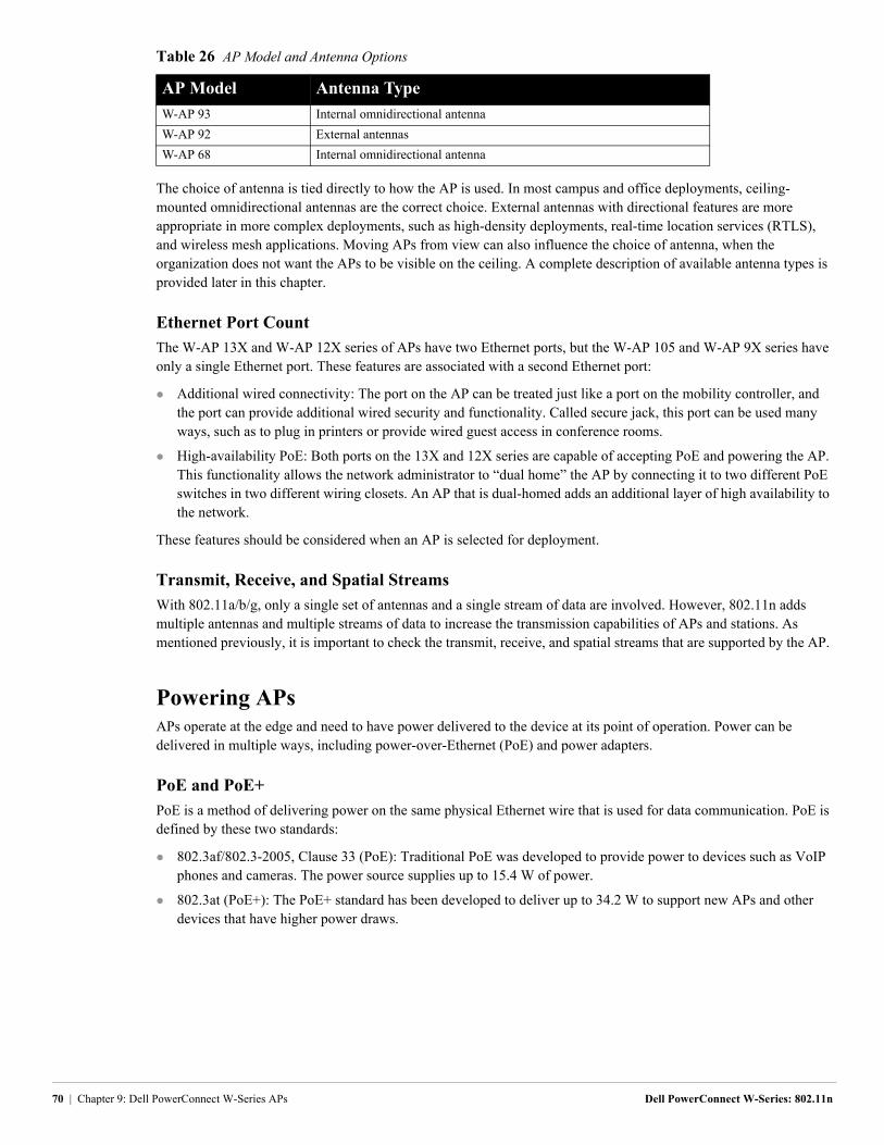
The choice of antenna is tied directly to how the AP is used. In most campus and office deployments, ceiling-mounted omnidirectional antennas are the correct choice. External antennas with directional features are more appropriate in more complex deployments, such as high-density deployments, real-time location services (RTLS), and wireless mesh applications. Moving APs from view can also influence the choice of antenna, when the organization does not want the APs to be visible on the ceiling. A complete description of available antenna types is provided later in this chapter.
Ethernet Port Count
The W-AP 13X and W-AP 12X series of APs have two Ethernet ports, but the W-AP 105 and W-AP 9X series have only a single Ethernet port. These features are associated with a second Ethernet port:
Additional wired connectivity: The port on the AP can be treated just like a port on the mobility controller, and the port can provide additional wired security and functionality. Called secure jack, this port can be used many ways, such as to plug in printers or provide wired guest access in conference rooms.
High-availability PoE: Both ports on the 13X and 12X series are capable of accepting PoE and powering the AP. This functionality allows the network administrator to “dual home” the AP by connecting it to two different PoE switches in two different wiring closets. An AP that is dual-homed adds an additional layer of high availability to the network.
These features should be considered when an AP is selected for deployment.
Transmit, Receive, and Spatial Streams
With 802.11a/b/g, only a single set of antennas and a single stream of data are involved. However, 802.11n adds multiple antennas and multiple streams of data to increase the transmission capabilities of APs and stations. As mentioned previously, it is important to check the transmit, receive, and spatial streams that are supported by the AP.
Powering APsAPs operate at the edge and need to have power delivered to the device at its point of operation. Power can be delivered in multiple ways, including power-over-Ethernet (PoE) and power adapters.
PoE and PoE+
PoE is a method of delivering power on the same physical Ethernet wire that is used for data communication. PoE is defined by these two standards:
802.3af/802.3-2005, Clause 33 (PoE): Traditional PoE was developed to provide power to devices such as VoIP phones and cameras. The power source supplies up to 15.4 W of power.
802.3at (PoE+): The PoE+ standard has been developed to deliver up to 34.2 W to support new APs and other devices that have higher power draws.
W-AP 93 Internal omnidirectional antenna
W-AP 92 External antennas
W-AP 68 Internal omnidirectional antenna
Table 26 AP Model and Antenna Options
AP Model Antenna Type
70 | Chapter 9: Dell PowerConnect W-Series APs Dell PowerConnect W-Series: 802.11n
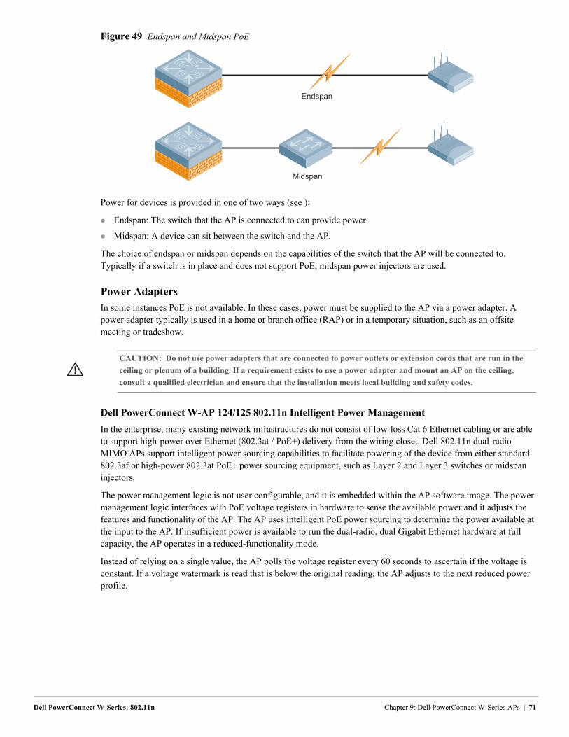
Figure 49 Endspan and Midspan PoE
Power for devices is provided in one of two ways (see ):
Endspan: The switch that the AP is connected to can provide power.
Midspan: A device can sit between the switch and the AP.
The choice of endspan or midspan depends on the capabilities of the switch that the AP will be connected to. Typically if a switch is in place and does not support PoE, midspan power injectors are used.
Power Adapters
In some instances PoE is not available. In these cases, power must be supplied to the AP via a power adapter. A power adapter typically is used in a home or branch office (RAP) or in a temporary situation, such as an offsite meeting or tradeshow.
Dell PowerConnect W-AP 124/125 802.11n Intelligent Power Management
In the enterprise, many existing network infrastructures do not consist of low-loss Cat 6 Ethernet cabling or are able to support high-power over Ethernet (802.3at / PoE+) delivery from the wiring closet. Dell 802.11n dual-radio MIMO APs support intelligent power sourcing capabilities to facilitate powering of the device from either standard 802.3af or high-power 802.3at PoE+ power sourcing equipment, such as Layer 2 and Layer 3 switches or midspan injectors.
The power management logic is not user configurable, and it is embedded within the AP software image. The power management logic interfaces with PoE voltage registers in hardware to sense the available power and it adjusts the features and functionality of the AP. The AP uses intelligent PoE power sourcing to determine the power available at the input to the AP. If insufficient power is available to run the dual-radio, dual Gigabit Ethernet hardware at full capacity, the AP operates in a reduced-functionality mode.
Instead of relying on a single value, the AP polls the voltage register every 60 seconds to ascertain if the voltage is constant. If a voltage watermark is read that is below the original reading, the AP adjusts to the next reduced power profile.
Endspan
Midspan
CAUTION: Do not use power adapters that are connected to power outlets or extension cords that are run in the
ceiling or plenum of a building. If a requirement exists to use a power adapter and mount an AP on the ceiling,
consult a qualified electrician and ensure that the installation meets local building and safety codes.
Dell PowerConnect W-Series: 802.11n Chapter 9: Dell PowerConnect W-Series APs | 71
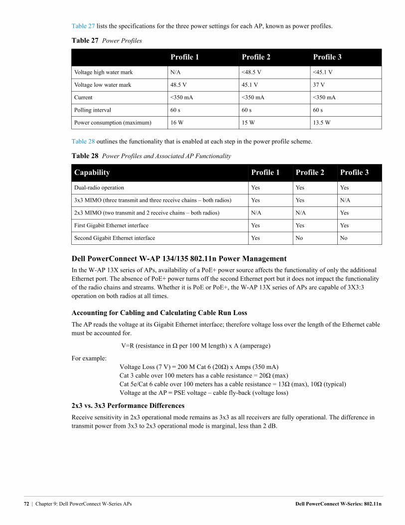
Table 27 lists the specifications for the three power settings for each AP, known as power profiles.
Table 28 outlines the functionality that is enabled at each step in the power profile scheme.
Dell PowerConnect W-AP 134/135 802.11n Power Management
In the W-AP 13X series of APs, availability of a PoE+ power source affects the functionality of only the additional Ethernet port. The absence of PoE+ power turns off the second Ethernet port but it does not impact the functionality of the radio chains and streams. Whether it is PoE or PoE+, the W-AP 13X series of APs are capable of 3X3:3 operation on both radios at all times.
Accounting for Cabling and Calculating Cable Run Loss
The AP reads the voltage at its Gigabit Ethernet interface; therefore voltage loss over the length of the Ethernet cable must be accounted for.
...... . . . . . . . . . .....V=R (resistance in Ω per 100 M length) x A (amperage)
For example:. . . . . . . . . . . . . . .Voltage Loss (7 V) = 200 M Cat 6 (20Ω) x Amps (350 mA) . . . . . . . . . . . . . . .Cat 3 cable over 100 meters has a cable resistance = 20Ω (max). . . . . . . . . . . . . . .Cat 5e/Cat 6 cable over 100 meters has a cable resistance = 13Ω (max), 10Ω (typical) . . . . . . . . . . . . . . .Voltage at the AP = PSE voltage – cable fly-back (voltage loss)
2x3 vs. 3x3 Performance Differences
Receive sensitivity in 2x3 operational mode remains as 3x3 as all receivers are fully operational. The difference in transmit power from 3x3 to 2x3 operational mode is marginal, less than 2 dB.
Table 27 Power Profiles
Profile 1 Profile 2 Profile 3
Voltage high water mark N/A <48.5 V <45.1 V
Voltage low water mark 48.5 V 45.1 V 37 V
Current <350 mA <350 mA <350 mA
Polling interval 60 s 60 s 60 s
Power consumption (maximum) 16 W 15 W 13.5 W
Table 28 Power Profiles and Associated AP Functionality
Capability Profile 1 Profile 2 Profile 3
Dual-radio operation Yes Yes Yes
3x3 MIMO (three transmit and three receive chains – both radios) Yes Yes N/A
2x3 MIMO (two transmit and 2 receive chains – both radios) N/A N/A Yes
First Gigabit Ethernet interface Yes Yes Yes
Second Gigabit Ethernet interface Yes No No
72 | Chapter 9: Dell PowerConnect W-Series APs Dell PowerConnect W-Series: 802.11n
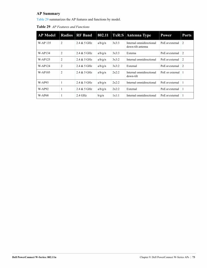
AP Summary
Table 29 summarizes the AP features and functions by model.
Table 29 AP Features and Functions
AP Model Radios RF Band 802.11 TxR:S Antenna Type Power Ports
W-AP 135 2 2.4 & 5 GHz a/b/g/n 3x3:3 Internal omnidirectional down-tilt antenna
PoE or external 2
W-AP134 2 2.4 & 5 GHz a/b/g/n 3x3:3 Externa PoE or external 2
W-AP125 2 2.4 & 5 GHz a/b/g/n 3x3:2 Internal omnidirectional PoE or external 2
W-AP124 2 2.4 & 5 GHz a/b/g/n 3x3:2 External PoE or external 2
W-AP105 2 2.4 & 5 GHz a/b/g/n 2x2:2 Internal omnidirectional down-tilt
PoE or external 1
W-AP93 1 2.4 & 5 GHz a/b/g/n 2x2:2 Internal omnidirectional PoE or external 1
W-AP92 1 2.4 & 5 GHz a/b/g/n 2x2:2 External PoE or external 1
W-AP68 1 2.4 GHz b/g/n 1x1:1 Internal omnidirectional PoE or external 1
Dell PowerConnect W-Series: 802.11n Chapter 9: Dell PowerConnect W-Series APs | 73

74 | Chapter 9: Dell PowerConnect W-Series APs Dell PowerConnect W-Series: 802.11n
Dell PowerConnect W-Series: 802.11n
Chapter 10: Conclusion
Dell PowerConnect W-Series goes beyond providing only high-speed 802.11n networks. The Dell PowerConnect W-Series solution delivers advanced client connectivity, network visibility and control, and strong network security in an integrated solution. Users receive wire-like speed with the convenience of mobility, which allows them to work where they need to and increases their productivity. Network administrators find that the Dell PowerConnect W-Series system solves many problems before the users can call or even notice that an issue has occurred. Dell PowerConnect W-Series makes it possible for wireless to be the default network connection for enterprise class deployments.
Chapter 10: Conclusion | 75