
PowerCenter Advanced Workflow Guide - Datacadamia
302
Informatica ® PowerCenter ® (Version 8.6.1) Advanced Workflow Guide
Transcript of PowerCenter Advanced Workflow Guide - Datacadamia

Informatica® PowerCenter® (Version 8.6.1)
Advanced Workflow Guide

PowerCenter Advanced Workflow Guide
Version 8.6.1 July 2009
Copyright (c) 1998–2009 Informatica Corporation. All rights reserved.
This software and documentation contain proprietary information of Informatica Corporation and are provided under a license agreement containing restrictions on use and disclosure and are also protected by copyright law. Reverse engineering of the software is prohibited. No part of this document may be reproduced or transmitted in any form, by any means (electronic, photocopying, recording or otherwise) without prior consent of Informatica Corporation. This Software may be protected by U.S. and/or international Patents and other Patents Pending.
Use, duplication, or disclosure of the Software by the U.S. Government is subject to the restrictions set forth in the applicable software license agreement and as provided in DFARS 227.7202-1(a) and 227.7702-3(a) (1995), DFARS 252.227-7013(c)(1)(ii) (OCT 1988), FAR 12.212(a) (1995), FAR 52.227-19, or FAR 52.227-14 (ALT III), as applicable.
The information in this product or documentation is subject to change without notice. If you find any problems in this product or documentation, please report them to us in writing.
Informatica, PowerCenter, PowerCenterRT, PowerCenter Connect, PowerCenter Data Analyzer, PowerExchange, PowerMart, Metadata Manager, Informatica Data Quality, Informatica Data Explorer, Informatica B2B Data Exchange and Informatica On Demand are trademarks or registered trademarks of Informatica Corporation in the United States and in jurisdictions throughout the world. All other company and product names may be trade names or trademarks of their respective owners.
Portions of this software and/or documentation are subject to copyright held by third parties, including without limitation: Copyright DataDirect Technologies. All rights reserved. Copyright © 2007 Adobe Systems Incorporated. All rights reserved. Copyright © Sun Microsystems. All rights reserved. Copyright © RSA Security Inc. All Rights Reserved. Copyright © Ordinal Technology Corp. All rights reserved. Copyright © Platon Data Technology GmbH. All rights reserved. Copyright © Melissa Data Corporation. All rights reserved. Copyright © Aandacht c.v. All rights reserved. Copyright 1996-2007 ComponentSource®. All rights reserved. Copyright Genivia, Inc. All rights reserved. Copyright 2007 Isomorphic Software. All rights reserved. Copyright © Meta Integration Technology, Inc. All rights reserved. Copyright © Microsoft. All rights reserved. Copyright © Oracle. All rights reserved. Copyright © AKS-Labs. All rights reserved. Copyright © Quovadx, Inc. All rights reserved. Copyright © SAP. All rights reserved. Copyright 2003, 2007 Instantiations, Inc. All rights reserved. Copyright © Intalio. All rights reserved.
This product includes software developed by the Apache Software Foundation (http://www.apache.org/), software copyright 2004-2005 Open Symphony (all rights reserved) and other software which is licensed under the Apache License, Version 2.0 (the “License”). You may obtain a copy of the License at http://www.apache.org/licenses/LICENSE-2.0. Unless required by applicable law or agreed to in writing, software distributed under the License is distributed on an “AS IS” BASIS, WITHOUT WARRANTIES OR CONDITIONS OF ANY KIND, either express or implied. See the License for the specific language governing permissions and limitations under the License.
This product includes software which was developed by Mozilla (http://www.mozilla.org/), software copyright The JBoss Group, LLC, all rights reserved; software copyright, Red Hat Middleware, LLC, all rights reserved; software copyright © 1999-2006 by Bruno Lowagie and Paulo Soares and other software which is licensed under the GNU Lesser General Public License Agreement, which may be found at http://www.gnu.org/licenses/lgpl.html. The materials are provided free of charge by Informatica, “as-is”, without warranty of any kind, either express or implied, including but not limited to the implied warranties of merchantability and fitness for a particular purpose.
The product includes ACE(TM) and TAO(TM) software copyrighted by Douglas C. Schmidt and his research group at Washington University, University of California, Irvine, and Vanderbilt University, Copyright (c) 1993-2006, all rights reserved.
This product includes software copyright (c) 2003-2007, Terence Parr. All rights reserved. Your right to use such materials is set forth in the license which may be found at http://www.antlr.org/license.html. The materials are provided free of charge by Informatica, “as-is”, without warranty of any kind, either express or implied, including but not limited to the implied warranties of merchantability and fitness for a particular purpose.
This product includes software developed by the OpenSSL Project for use in the OpenSSL Toolkit (copyright The OpenSSL Project. All Rights Reserved) and redistribution of this software is subject to terms available at http://www.openssl.org.
This product includes Curl software which is Copyright 1996-2007, Daniel Stenberg, <[email protected]>. All Rights Reserved. Permissions and limitations regarding this software are subject to terms available at http://curl.haxx.se/docs/copyright.html. Permission to use, copy, modify, and distribute this software for any purpose with or without fee is hereby granted, provided that the above copyright notice and this permission notice appear in all copies.
The product includes software copyright 2001-2005 (C) MetaStuff, Ltd. All Rights Reserved. Permissions and limitations regarding this software are subject to terms available at http://www.dom4j.org/license.html.
The product includes software copyright (c) 2004-2007, The Dojo Foundation. All Rights Reserved. Permissions and limitations regarding this software are subject to terms available at http://svn.dojotoolkit.org/dojo/trunk/LICENSE.
This product includes ICU software which is copyright (c) 1995-2003 International Business Machines Corporation and others. All rights reserved. Permissions and limitations regarding this software are subject to terms available at http://www-306.ibm.com/software/globalization/icu/license.jsp
This product includes software copyright (C) 1996-2006 Per Bothner. All rights reserved. Your right to use such materials is set forth in the license which may be found at http://www.gnu.org/software/kawa/Software-License.html.
This product includes OSSP UUID software which is Copyright (c) 2002 Ralf S. Engelschall, Copyright (c) 2002 The OSSP Project Copyright (c) 2002 Cable & Wireless Deutschland. Permissions and limitations regarding this software are subject to terms available at http://www.opensource.org/licenses/mit-license.php.
This product includes software developed by Boost (http://www.boost.org/) or under the Boost software license. Permissions and limitations regarding this software are subject to terms available at http://www.boost.org/LICENSE_1_0.txt.
This product includes software copyright © 1997-2007 University of Cambridge. Permissions and limitations regarding this software are subject to terms available at http://www.pcre.org/license.txt.
This product includes software copyright (c) 2007 The Eclipse Foundation. All Rights Reserved. Permissions and limitations regarding this software are subject to terms available at http://www.eclipse.org/org/documents/epl-v10.php.
The product includes the zlib library copyright (c) 1995-2005 Jean-loup Gailly and Mark Adler.
This product includes software licensed under the terms at http://www.tcl.tk/software/tcltk/license.html.
This product includes software licensed under the terms at http://www.bosrup.com/web/overlib/?License.
This product includes software licensed under the terms at http://www.stlport.org/doc/license.html.
This product includes software licensed under the Academic Free License (http://www.opensource.org/licenses/afl-3.0.php). This product includes software copyright © 2003-2006 Joe WaInes, 2006-2007 XStream Committers. All rights reserved. Permissions and limitations regarding this software are subject to terms available at http://xstream.codehaus.org/license.html. This product includes software developed by the Indiana University Extreme! Lab. For further information please visit http://www.extreme.indiana.edu/.
This Software is protected by U.S. Patent Numbers 6,208,990; 6,044,374; 6,014,670; 6,032,158; 5,794,246; 6,339,775; 6,850,947; 6,895,471; 7,254,590 and other U.S. Patents Pending.
DISCLAIMER: Informatica Corporation provides this documentation “as is” without warranty of any kind, either express or implied, including, but not limited to, the implied warranties of non-infringement, merchantability, or use for a particular purpose. Informatica Corporation does not warrant that this software or documentation is error free. The information provided in this software or documentation may include technical inaccuracies or typographical errors. The information in this software and documentation is subject to change at any time without notice.
Part Number: PC-AWG-86100-0003

Table of Contents
Preface . . . . . . . . . . . . . . . . . . . . . . . . . . . . . . . . . . . . . . . . . . . . . . . . . . . . . . . . . . . . . xvInformatica Resources . . . . . . . . . . . . . . . . . . . . . . . . . . . . . . . . . . . . . . . . . . . . . . . . . . . . . xv
Informatica Customer Portal . . . . . . . . . . . . . . . . . . . . . . . . . . . . . . . . . . . . . . . . . . . . . xv
Informatica Documentation . . . . . . . . . . . . . . . . . . . . . . . . . . . . . . . . . . . . . . . . . . . . . xv
Informatica Web Site . . . . . . . . . . . . . . . . . . . . . . . . . . . . . . . . . . . . . . . . . . . . . . . . . . xv
Informatica How-To Library . . . . . . . . . . . . . . . . . . . . . . . . . . . . . . . . . . . . . . . . . . . . . xv
Informatica Knowledge Base . . . . . . . . . . . . . . . . . . . . . . . . . . . . . . . . . . . . . . . . . . . . . xvi
Informatica Multimedia Knowledge Base . . . . . . . . . . . . . . . . . . . . . . . . . . . . . . . . . . . . xvi
Informatica Global Customer Support . . . . . . . . . . . . . . . . . . . . . . . . . . . . . . . . . . . . . . xvi
Chapter 1: Understanding Pipeline Partitioning . . . . . . . . . . . . . . . . . . . . . . . . . . . . . . 1Overview . . . . . . . . . . . . . . . . . . . . . . . . . . . . . . . . . . . . . . . . . . . . . . . . . . . . . . . . . . . . . . . 1
Partitioning Attributes . . . . . . . . . . . . . . . . . . . . . . . . . . . . . . . . . . . . . . . . . . . . . . . . . . . . . 2
Partition Points . . . . . . . . . . . . . . . . . . . . . . . . . . . . . . . . . . . . . . . . . . . . . . . . . . . . . . . 2
Number of Partitions . . . . . . . . . . . . . . . . . . . . . . . . . . . . . . . . . . . . . . . . . . . . . . . . . . . 3
Partition Types . . . . . . . . . . . . . . . . . . . . . . . . . . . . . . . . . . . . . . . . . . . . . . . . . . . . . . . . 4
Dynamic Partitioning . . . . . . . . . . . . . . . . . . . . . . . . . . . . . . . . . . . . . . . . . . . . . . . . . . . . . . 4
Configuring Dynamic Partitioning . . . . . . . . . . . . . . . . . . . . . . . . . . . . . . . . . . . . . . . . . 5
Rules and Guidelines for Dynamic Partitioning . . . . . . . . . . . . . . . . . . . . . . . . . . . . . . . . 5
Using Dynamic Partitioning with Partition Types . . . . . . . . . . . . . . . . . . . . . . . . . . . . . . . 6
Configuring Partition-Level Attributes . . . . . . . . . . . . . . . . . . . . . . . . . . . . . . . . . . . . . . 6
Cache Partitioning . . . . . . . . . . . . . . . . . . . . . . . . . . . . . . . . . . . . . . . . . . . . . . . . . . . . . . . . 6
Mapping Variables in Partitioned Pipelines . . . . . . . . . . . . . . . . . . . . . . . . . . . . . . . . . . . . . . 7
Partitioning Rules . . . . . . . . . . . . . . . . . . . . . . . . . . . . . . . . . . . . . . . . . . . . . . . . . . . . . . . . . 8
Partition Restrictions for Editing Objects . . . . . . . . . . . . . . . . . . . . . . . . . . . . . . . . . . . . 8
Partition Restrictions for PowerExchange . . . . . . . . . . . . . . . . . . . . . . . . . . . . . . . . . . . . . 8
Configuring Partitioning . . . . . . . . . . . . . . . . . . . . . . . . . . . . . . . . . . . . . . . . . . . . . . . . . . . . 9
Adding Partition Points to a Pipeline . . . . . . . . . . . . . . . . . . . . . . . . . . . . . . . . . . . . . . . . 9
Configuring a Partition Point . . . . . . . . . . . . . . . . . . . . . . . . . . . . . . . . . . . . . . . . . . . . 10
Partition Points Node . . . . . . . . . . . . . . . . . . . . . . . . . . . . . . . . . . . . . . . . . . . . . . . . . . 11
Non-Partition Points Node . . . . . . . . . . . . . . . . . . . . . . . . . . . . . . . . . . . . . . . . . . . . . . 11
Chapter 2: Partition Points . . . . . . . . . . . . . . . . . . . . . . . . . . . . . . . . . . . . . . . . . . . . . 13Overview . . . . . . . . . . . . . . . . . . . . . . . . . . . . . . . . . . . . . . . . . . . . . . . . . . . . . . . . . . . . . . 13
Adding and Deleting Partition Points . . . . . . . . . . . . . . . . . . . . . . . . . . . . . . . . . . . . . . . . . 14
Rules and Guidelines . . . . . . . . . . . . . . . . . . . . . . . . . . . . . . . . . . . . . . . . . . . . . . . . . . 14
Partitioning Relational Sources . . . . . . . . . . . . . . . . . . . . . . . . . . . . . . . . . . . . . . . . . . . . . . 16
Entering an SQL Query . . . . . . . . . . . . . . . . . . . . . . . . . . . . . . . . . . . . . . . . . . . . . . . . 16
Entering a Filter Condition . . . . . . . . . . . . . . . . . . . . . . . . . . . . . . . . . . . . . . . . . . . . . . 16
Partitioning File Sources . . . . . . . . . . . . . . . . . . . . . . . . . . . . . . . . . . . . . . . . . . . . . . . . . . . 17
Rules and Guidelines for Partitioning File Sources . . . . . . . . . . . . . . . . . . . . . . . . . . . . . 17
Using One Thread to Read a File Source . . . . . . . . . . . . . . . . . . . . . . . . . . . . . . . . . . . . 18
i i i

Using Multiple Threads to Read a File Source . . . . . . . . . . . . . . . . . . . . . . . . . . . . . . . . 18
Configuring for File Partitioning . . . . . . . . . . . . . . . . . . . . . . . . . . . . . . . . . . . . . . . . . . 18
Partitioning Relational Targets . . . . . . . . . . . . . . . . . . . . . . . . . . . . . . . . . . . . . . . . . . . . . . 21
Database Compatibility . . . . . . . . . . . . . . . . . . . . . . . . . . . . . . . . . . . . . . . . . . . . . . . . 21
Partitioning File Targets . . . . . . . . . . . . . . . . . . . . . . . . . . . . . . . . . . . . . . . . . . . . . . . . . . . 22
Configuring Connection Settings . . . . . . . . . . . . . . . . . . . . . . . . . . . . . . . . . . . . . . . . . 22
Configuring File Properties . . . . . . . . . . . . . . . . . . . . . . . . . . . . . . . . . . . . . . . . . . . . . . 22
Partitioning Custom Transformations . . . . . . . . . . . . . . . . . . . . . . . . . . . . . . . . . . . . . . . . . 24
Working with Multiple Partitions . . . . . . . . . . . . . . . . . . . . . . . . . . . . . . . . . . . . . . . . . 24
Creating Partition Points . . . . . . . . . . . . . . . . . . . . . . . . . . . . . . . . . . . . . . . . . . . . . . . 25
Working with Threads . . . . . . . . . . . . . . . . . . . . . . . . . . . . . . . . . . . . . . . . . . . . . . . . . 25
Partitioning Joiner Transformations . . . . . . . . . . . . . . . . . . . . . . . . . . . . . . . . . . . . . . . . . . . 26
Partitioning Sorted Joiner Transformations . . . . . . . . . . . . . . . . . . . . . . . . . . . . . . . . . . 26
Using Sorted Flat Files . . . . . . . . . . . . . . . . . . . . . . . . . . . . . . . . . . . . . . . . . . . . . . . . . 27
Using Sorted Relational Data . . . . . . . . . . . . . . . . . . . . . . . . . . . . . . . . . . . . . . . . . . . . 29
Using Sorter Transformations . . . . . . . . . . . . . . . . . . . . . . . . . . . . . . . . . . . . . . . . . . . . 30
Optimizing Sorted Joiner Transformations with Partitions . . . . . . . . . . . . . . . . . . . . . . . 30
Partitioning Lookup Transformations . . . . . . . . . . . . . . . . . . . . . . . . . . . . . . . . . . . . . . . . . 31
Cache Partitioning Lookup Transformations . . . . . . . . . . . . . . . . . . . . . . . . . . . . . . . . . 31
Partitioning Pipeline Lookup Transformation Cache . . . . . . . . . . . . . . . . . . . . . . . . . . . . 32
Partitioning Sequence Generator Transformations . . . . . . . . . . . . . . . . . . . . . . . . . . . . . . . . 33
Partitioning Sorter Transformations . . . . . . . . . . . . . . . . . . . . . . . . . . . . . . . . . . . . . . . . . . . 33
Configuring Sorter Transformation Work Directories . . . . . . . . . . . . . . . . . . . . . . . . . . . 33
Partitioning XML Generator Transformations . . . . . . . . . . . . . . . . . . . . . . . . . . . . . . . . . . . 33
Restrictions for Transformations . . . . . . . . . . . . . . . . . . . . . . . . . . . . . . . . . . . . . . . . . . . . . 33
Chapter 3: Partition Types . . . . . . . . . . . . . . . . . . . . . . . . . . . . . . . . . . . . . . . . . . . . . . 35Overview . . . . . . . . . . . . . . . . . . . . . . . . . . . . . . . . . . . . . . . . . . . . . . . . . . . . . . . . . . . . . . 35
Setting Partition Types in the Pipeline . . . . . . . . . . . . . . . . . . . . . . . . . . . . . . . . . . . . . . 36
Setting Partition Types . . . . . . . . . . . . . . . . . . . . . . . . . . . . . . . . . . . . . . . . . . . . . . . . . . . . 37
Database Partitioning Partition Type . . . . . . . . . . . . . . . . . . . . . . . . . . . . . . . . . . . . . . . . . . 38
Partitioning Database Sources . . . . . . . . . . . . . . . . . . . . . . . . . . . . . . . . . . . . . . . . . . . . 38
Target Database Partitioning . . . . . . . . . . . . . . . . . . . . . . . . . . . . . . . . . . . . . . . . . . . . . 40
Rules and Guidelines . . . . . . . . . . . . . . . . . . . . . . . . . . . . . . . . . . . . . . . . . . . . . . . . . . 41
Hash Auto-Keys Partition Type . . . . . . . . . . . . . . . . . . . . . . . . . . . . . . . . . . . . . . . . . . . . . . 41
Hash User Keys Partition Type . . . . . . . . . . . . . . . . . . . . . . . . . . . . . . . . . . . . . . . . . . . . . . 42
Key Range Partition Type . . . . . . . . . . . . . . . . . . . . . . . . . . . . . . . . . . . . . . . . . . . . . . . . . . 42
Adding a Partition Key . . . . . . . . . . . . . . . . . . . . . . . . . . . . . . . . . . . . . . . . . . . . . . . . . 43
Adding Key Ranges . . . . . . . . . . . . . . . . . . . . . . . . . . . . . . . . . . . . . . . . . . . . . . . . . . . 44
Pass-Through Partition Type . . . . . . . . . . . . . . . . . . . . . . . . . . . . . . . . . . . . . . . . . . . . . . . . 45
Round-Robin Partition Type . . . . . . . . . . . . . . . . . . . . . . . . . . . . . . . . . . . . . . . . . . . . . . . . 46
Chapter 4: Pushdown Optimization. . . . . . . . . . . . . . . . . . . . . . . . . . . . . . . . . . . . . . . 47Overview . . . . . . . . . . . . . . . . . . . . . . . . . . . . . . . . . . . . . . . . . . . . . . . . . . . . . . . . . . . . . . 47
Pushdown Optimization Types . . . . . . . . . . . . . . . . . . . . . . . . . . . . . . . . . . . . . . . . . . . . . . 48
Running Source-Side Pushdown Optimization Sessions . . . . . . . . . . . . . . . . . . . . . . . . . 48
iv Table of Contents
Running Target-Side Pushdown Optimization Sessions . . . . . . . . . . . . . . . . . . . . . . . . . . 48
Running Full Pushdown Optimization Sessions . . . . . . . . . . . . . . . . . . . . . . . . . . . . . . . 48
Active and Idle Databases . . . . . . . . . . . . . . . . . . . . . . . . . . . . . . . . . . . . . . . . . . . . . . . . . . 49
Working with Databases . . . . . . . . . . . . . . . . . . . . . . . . . . . . . . . . . . . . . . . . . . . . . . . . . . . 50
Comparing the Output of the Integration Service and Databases . . . . . . . . . . . . . . . . . . . 50
Using ODBC Drivers . . . . . . . . . . . . . . . . . . . . . . . . . . . . . . . . . . . . . . . . . . . . . . . . . . 51
Rules and Guidelines for Netezza . . . . . . . . . . . . . . . . . . . . . . . . . . . . . . . . . . . . . . . . . 52
Pushdown Compatibility . . . . . . . . . . . . . . . . . . . . . . . . . . . . . . . . . . . . . . . . . . . . . . . . . . 52
Incompatible Users for Database Connections . . . . . . . . . . . . . . . . . . . . . . . . . . . . . . . . 53
Qualifying Names of Tables in Idle Databases . . . . . . . . . . . . . . . . . . . . . . . . . . . . . . . . 53
Working with Dates . . . . . . . . . . . . . . . . . . . . . . . . . . . . . . . . . . . . . . . . . . . . . . . . . . . . . . 54
Working with Expressions . . . . . . . . . . . . . . . . . . . . . . . . . . . . . . . . . . . . . . . . . . . . . . . . . . 55
Operators . . . . . . . . . . . . . . . . . . . . . . . . . . . . . . . . . . . . . . . . . . . . . . . . . . . . . . . . . . 55
Variables . . . . . . . . . . . . . . . . . . . . . . . . . . . . . . . . . . . . . . . . . . . . . . . . . . . . . . . . . . . 56
Functions . . . . . . . . . . . . . . . . . . . . . . . . . . . . . . . . . . . . . . . . . . . . . . . . . . . . . . . . . . 56
Error Handling, Logging, and Recovery . . . . . . . . . . . . . . . . . . . . . . . . . . . . . . . . . . . . . . . . 60
Error Handling . . . . . . . . . . . . . . . . . . . . . . . . . . . . . . . . . . . . . . . . . . . . . . . . . . . . . . 60
Logging . . . . . . . . . . . . . . . . . . . . . . . . . . . . . . . . . . . . . . . . . . . . . . . . . . . . . . . . . . . . 60
Recovery . . . . . . . . . . . . . . . . . . . . . . . . . . . . . . . . . . . . . . . . . . . . . . . . . . . . . . . . . . . 60
Working with Slowly Changing Dimensions . . . . . . . . . . . . . . . . . . . . . . . . . . . . . . . . . . . . . 61
Working with Sequences and Views . . . . . . . . . . . . . . . . . . . . . . . . . . . . . . . . . . . . . . . . . . . 61
Sequences . . . . . . . . . . . . . . . . . . . . . . . . . . . . . . . . . . . . . . . . . . . . . . . . . . . . . . . . . . 61
Views . . . . . . . . . . . . . . . . . . . . . . . . . . . . . . . . . . . . . . . . . . . . . . . . . . . . . . . . . . . . . 62
Troubleshooting Orphaned Sequences and Views . . . . . . . . . . . . . . . . . . . . . . . . . . . . . . 63
Using the $$PushdownConfig Mapping Parameter . . . . . . . . . . . . . . . . . . . . . . . . . . . . . . . . 65
Configuring Sessions for Pushdown Optimization . . . . . . . . . . . . . . . . . . . . . . . . . . . . . . . . 66
Pushdown Options . . . . . . . . . . . . . . . . . . . . . . . . . . . . . . . . . . . . . . . . . . . . . . . . . . . . 66
Partitioning . . . . . . . . . . . . . . . . . . . . . . . . . . . . . . . . . . . . . . . . . . . . . . . . . . . . . . . . . 66
Target Load Rules . . . . . . . . . . . . . . . . . . . . . . . . . . . . . . . . . . . . . . . . . . . . . . . . . . . . 68
Viewing Pushdown Groups . . . . . . . . . . . . . . . . . . . . . . . . . . . . . . . . . . . . . . . . . . . . . . 68
Chapter 5: Pushdown Optimization and Transformations . . . . . . . . . . . . . . . . . . . . . 71Overview . . . . . . . . . . . . . . . . . . . . . . . . . . . . . . . . . . . . . . . . . . . . . . . . . . . . . . . . . . . . . . 71
Rules and Guidelines . . . . . . . . . . . . . . . . . . . . . . . . . . . . . . . . . . . . . . . . . . . . . . . . . . 72
Aggregator Transformation . . . . . . . . . . . . . . . . . . . . . . . . . . . . . . . . . . . . . . . . . . . . . . . . . 73
Expression Transformation . . . . . . . . . . . . . . . . . . . . . . . . . . . . . . . . . . . . . . . . . . . . . . . . . 73
Filter Transformation . . . . . . . . . . . . . . . . . . . . . . . . . . . . . . . . . . . . . . . . . . . . . . . . . . . . . 74
Joiner Transformation . . . . . . . . . . . . . . . . . . . . . . . . . . . . . . . . . . . . . . . . . . . . . . . . . . . . . 74
Lookup Transformation . . . . . . . . . . . . . . . . . . . . . . . . . . . . . . . . . . . . . . . . . . . . . . . . . . . 75
Unconnected Lookup Transformation . . . . . . . . . . . . . . . . . . . . . . . . . . . . . . . . . . . . . . 76
Lookup Transformation with an SQL Override . . . . . . . . . . . . . . . . . . . . . . . . . . . . . . . 76
Router Transformation . . . . . . . . . . . . . . . . . . . . . . . . . . . . . . . . . . . . . . . . . . . . . . . . . . . . 76
Sequence Generator Transformation . . . . . . . . . . . . . . . . . . . . . . . . . . . . . . . . . . . . . . . . . . 77
Sorter Transformation . . . . . . . . . . . . . . . . . . . . . . . . . . . . . . . . . . . . . . . . . . . . . . . . . . . . . 78
Source Qualifier Transformation . . . . . . . . . . . . . . . . . . . . . . . . . . . . . . . . . . . . . . . . . . . . . 78
Source Qualifier Transformation with an SQL Override . . . . . . . . . . . . . . . . . . . . . . . . . 79
Table of Contents v

Target . . . . . . . . . . . . . . . . . . . . . . . . . . . . . . . . . . . . . . . . . . . . . . . . . . . . . . . . . . . . . . . . 79
Union Transformation . . . . . . . . . . . . . . . . . . . . . . . . . . . . . . . . . . . . . . . . . . . . . . . . . . . . 80
Update Strategy Transformation . . . . . . . . . . . . . . . . . . . . . . . . . . . . . . . . . . . . . . . . . . . . . 81
Chapter 6: Real-time Processing. . . . . . . . . . . . . . . . . . . . . . . . . . . . . . . . . . . . . . . . . 83Overview . . . . . . . . . . . . . . . . . . . . . . . . . . . . . . . . . . . . . . . . . . . . . . . . . . . . . . . . . . . . . . 83
Understanding Real-time Data . . . . . . . . . . . . . . . . . . . . . . . . . . . . . . . . . . . . . . . . . . . . . . 84
Messages and Message Queues. . . . . . . . . . . . . . . . . . . . . . . . . . . . . . . . . . . . . . . . . . . . 84
Web Service Messages . . . . . . . . . . . . . . . . . . . . . . . . . . . . . . . . . . . . . . . . . . . . . . . . . . 85
Change Data from PowerExchange Change Data Capture Sources . . . . . . . . . . . . . . . . . . 85
Configuring Real-time Sessions . . . . . . . . . . . . . . . . . . . . . . . . . . . . . . . . . . . . . . . . . . . . . . 86
Terminating Conditions . . . . . . . . . . . . . . . . . . . . . . . . . . . . . . . . . . . . . . . . . . . . . . . . . . . 86
Idle Time . . . . . . . . . . . . . . . . . . . . . . . . . . . . . . . . . . . . . . . . . . . . . . . . . . . . . . . . . . . 87
Message Count . . . . . . . . . . . . . . . . . . . . . . . . . . . . . . . . . . . . . . . . . . . . . . . . . . . . . . . 87
Reader Time Limit . . . . . . . . . . . . . . . . . . . . . . . . . . . . . . . . . . . . . . . . . . . . . . . . . . . . 87
Flush Latency . . . . . . . . . . . . . . . . . . . . . . . . . . . . . . . . . . . . . . . . . . . . . . . . . . . . . . . . . . . 87
Commit Type . . . . . . . . . . . . . . . . . . . . . . . . . . . . . . . . . . . . . . . . . . . . . . . . . . . . . . . . . . . 88
Message Recovery . . . . . . . . . . . . . . . . . . . . . . . . . . . . . . . . . . . . . . . . . . . . . . . . . . . . . . . . 88
Prerequisites . . . . . . . . . . . . . . . . . . . . . . . . . . . . . . . . . . . . . . . . . . . . . . . . . . . . . . . . 89
Steps to Enable Message Recovery . . . . . . . . . . . . . . . . . . . . . . . . . . . . . . . . . . . . . . . . . 89
Recovery File . . . . . . . . . . . . . . . . . . . . . . . . . . . . . . . . . . . . . . . . . . . . . . . . . . . . . . . . . . . 89
Message Processing . . . . . . . . . . . . . . . . . . . . . . . . . . . . . . . . . . . . . . . . . . . . . . . . . . . . 90
Message Recovery . . . . . . . . . . . . . . . . . . . . . . . . . . . . . . . . . . . . . . . . . . . . . . . . . . . . . 90
Session Recovery Data Flush . . . . . . . . . . . . . . . . . . . . . . . . . . . . . . . . . . . . . . . . . . . . . 90
Recovery Table . . . . . . . . . . . . . . . . . . . . . . . . . . . . . . . . . . . . . . . . . . . . . . . . . . . . . . . . . . 91
PM_REC_STATE Table . . . . . . . . . . . . . . . . . . . . . . . . . . . . . . . . . . . . . . . . . . . . . . . . 91
Message Processing . . . . . . . . . . . . . . . . . . . . . . . . . . . . . . . . . . . . . . . . . . . . . . . . . . . . 91
Message Recovery . . . . . . . . . . . . . . . . . . . . . . . . . . . . . . . . . . . . . . . . . . . . . . . . . . . . . 91
Recovery Queue and Recovery Topic . . . . . . . . . . . . . . . . . . . . . . . . . . . . . . . . . . . . . . . . . . 92
Message Processing . . . . . . . . . . . . . . . . . . . . . . . . . . . . . . . . . . . . . . . . . . . . . . . . . . . . 92
Message Recovery . . . . . . . . . . . . . . . . . . . . . . . . . . . . . . . . . . . . . . . . . . . . . . . . . . . . . 93
Recovery Ignore List . . . . . . . . . . . . . . . . . . . . . . . . . . . . . . . . . . . . . . . . . . . . . . . . . . . . . . 93
Stopping Real-time Sessions . . . . . . . . . . . . . . . . . . . . . . . . . . . . . . . . . . . . . . . . . . . . . . . . 93
Restarting and Recovering Real-time Sessions . . . . . . . . . . . . . . . . . . . . . . . . . . . . . . . . . . . . 94
Restarting Real-time Sessions . . . . . . . . . . . . . . . . . . . . . . . . . . . . . . . . . . . . . . . . . . . . 94
Recovering Real-time Sessions . . . . . . . . . . . . . . . . . . . . . . . . . . . . . . . . . . . . . . . . . . . . 94
Restart and Recover Commands . . . . . . . . . . . . . . . . . . . . . . . . . . . . . . . . . . . . . . . . . . 95
Rules and Guidelines . . . . . . . . . . . . . . . . . . . . . . . . . . . . . . . . . . . . . . . . . . . . . . . . . . . . . 95
Rules and Guidelines for Real-time Sessions . . . . . . . . . . . . . . . . . . . . . . . . . . . . . . . . . . 95
Rules and Guidelines for Message Recovery . . . . . . . . . . . . . . . . . . . . . . . . . . . . . . . . . . 95
Real-time Processing Example . . . . . . . . . . . . . . . . . . . . . . . . . . . . . . . . . . . . . . . . . . . . . . . 96
Informatica Real-time Products . . . . . . . . . . . . . . . . . . . . . . . . . . . . . . . . . . . . . . . . . . . . . . 97
Chapter 7: Commit Points . . . . . . . . . . . . . . . . . . . . . . . . . . . . . . . . . . . . . . . . . . . . . . 99Overview . . . . . . . . . . . . . . . . . . . . . . . . . . . . . . . . . . . . . . . . . . . . . . . . . . . . . . . . . . . . . . 99
Target-Based Commits . . . . . . . . . . . . . . . . . . . . . . . . . . . . . . . . . . . . . . . . . . . . . . . . . . . 100
vi Table of Contents

Source-Based Commits . . . . . . . . . . . . . . . . . . . . . . . . . . . . . . . . . . . . . . . . . . . . . . . . . . . 100
Determining the Commit Source . . . . . . . . . . . . . . . . . . . . . . . . . . . . . . . . . . . . . . . . 101
Switching from Source-Based to Target-Based Commit . . . . . . . . . . . . . . . . . . . . . . . . . 102
User-Defined Commits . . . . . . . . . . . . . . . . . . . . . . . . . . . . . . . . . . . . . . . . . . . . . . . . . . . 104
Rolling Back Transactions . . . . . . . . . . . . . . . . . . . . . . . . . . . . . . . . . . . . . . . . . . . . . . 104
Understanding Transaction Control . . . . . . . . . . . . . . . . . . . . . . . . . . . . . . . . . . . . . . . . . . 106
Transformation Scope . . . . . . . . . . . . . . . . . . . . . . . . . . . . . . . . . . . . . . . . . . . . . . . . . 107
Understanding Transaction Control Units . . . . . . . . . . . . . . . . . . . . . . . . . . . . . . . . . . 109
Rules and Guidelines . . . . . . . . . . . . . . . . . . . . . . . . . . . . . . . . . . . . . . . . . . . . . . . . . 109
Creating Target Files by Transaction . . . . . . . . . . . . . . . . . . . . . . . . . . . . . . . . . . . . . . 110
Setting Commit Properties . . . . . . . . . . . . . . . . . . . . . . . . . . . . . . . . . . . . . . . . . . . . . . . . 110
Chapter 8: Row Error Logging. . . . . . . . . . . . . . . . . . . . . . . . . . . . . . . . . . . . . . . . . . 113Overview . . . . . . . . . . . . . . . . . . . . . . . . . . . . . . . . . . . . . . . . . . . . . . . . . . . . . . . . . . . . . 113
Error Log Code Pages . . . . . . . . . . . . . . . . . . . . . . . . . . . . . . . . . . . . . . . . . . . . . . . . . 114
Understanding the Error Log Tables . . . . . . . . . . . . . . . . . . . . . . . . . . . . . . . . . . . . . . . . . 114
PMERR_DATA . . . . . . . . . . . . . . . . . . . . . . . . . . . . . . . . . . . . . . . . . . . . . . . . . . . . . 114
PMERR_MSG . . . . . . . . . . . . . . . . . . . . . . . . . . . . . . . . . . . . . . . . . . . . . . . . . . . . . . 116
PMERR_SESS . . . . . . . . . . . . . . . . . . . . . . . . . . . . . . . . . . . . . . . . . . . . . . . . . . . . . . 117
PMERR_TRANS . . . . . . . . . . . . . . . . . . . . . . . . . . . . . . . . . . . . . . . . . . . . . . . . . . . . 118
Understanding the Error Log File . . . . . . . . . . . . . . . . . . . . . . . . . . . . . . . . . . . . . . . . . . . 119
Configuring Error Log Options . . . . . . . . . . . . . . . . . . . . . . . . . . . . . . . . . . . . . . . . . . . . . 120
Chapter 9: Workflow Recovery . . . . . . . . . . . . . . . . . . . . . . . . . . . . . . . . . . . . . . . . . 123Overview . . . . . . . . . . . . . . . . . . . . . . . . . . . . . . . . . . . . . . . . . . . . . . . . . . . . . . . . . . . . . 123
State of Operation . . . . . . . . . . . . . . . . . . . . . . . . . . . . . . . . . . . . . . . . . . . . . . . . . . . . . . 124
Workflow State of Operation . . . . . . . . . . . . . . . . . . . . . . . . . . . . . . . . . . . . . . . . . . . 124
Session State of Operation . . . . . . . . . . . . . . . . . . . . . . . . . . . . . . . . . . . . . . . . . . . . . 124
Target Recovery Tables . . . . . . . . . . . . . . . . . . . . . . . . . . . . . . . . . . . . . . . . . . . . . . . . 125
Recovery Options . . . . . . . . . . . . . . . . . . . . . . . . . . . . . . . . . . . . . . . . . . . . . . . . . . . . . . . 127
Suspending the Workflow . . . . . . . . . . . . . . . . . . . . . . . . . . . . . . . . . . . . . . . . . . . . . . . . . 128
Configuring Suspension Email . . . . . . . . . . . . . . . . . . . . . . . . . . . . . . . . . . . . . . . . . . 128
Configuring Workflow Recovery . . . . . . . . . . . . . . . . . . . . . . . . . . . . . . . . . . . . . . . . . . . . 129
Recovering Stopped, Aborted, and Terminated Workflows . . . . . . . . . . . . . . . . . . . . . . 129
Recovering Suspended Workflows . . . . . . . . . . . . . . . . . . . . . . . . . . . . . . . . . . . . . . . . 129
Configuring Task Recovery . . . . . . . . . . . . . . . . . . . . . . . . . . . . . . . . . . . . . . . . . . . . . . . . 129
Task Recovery Strategies . . . . . . . . . . . . . . . . . . . . . . . . . . . . . . . . . . . . . . . . . . . . . . . 130
Automatically Recovering Terminated Tasks . . . . . . . . . . . . . . . . . . . . . . . . . . . . . . . . . 131
Resuming Sessions . . . . . . . . . . . . . . . . . . . . . . . . . . . . . . . . . . . . . . . . . . . . . . . . . . . . . . 132
Working with Repeatable Data . . . . . . . . . . . . . . . . . . . . . . . . . . . . . . . . . . . . . . . . . . . . . 133
Source Repeatability . . . . . . . . . . . . . . . . . . . . . . . . . . . . . . . . . . . . . . . . . . . . . . . . . . 133
Transformation Repeatability . . . . . . . . . . . . . . . . . . . . . . . . . . . . . . . . . . . . . . . . . . . 133
Configuring a Mapping for Recovery . . . . . . . . . . . . . . . . . . . . . . . . . . . . . . . . . . . . . . 134
Steps to Recover Workflows and Tasks . . . . . . . . . . . . . . . . . . . . . . . . . . . . . . . . . . . . . . . . 136
Recovering a Workflow . . . . . . . . . . . . . . . . . . . . . . . . . . . . . . . . . . . . . . . . . . . . . . . . 136
Recovering a Session . . . . . . . . . . . . . . . . . . . . . . . . . . . . . . . . . . . . . . . . . . . . . . . . . . 137
Table of Contents vii

Recovering a Workflow From a Session . . . . . . . . . . . . . . . . . . . . . . . . . . . . . . . . . . . . 137
Rules and Guidelines for Session Recovery . . . . . . . . . . . . . . . . . . . . . . . . . . . . . . . . . . . . . 138
Configuring Recovery to Resume from the Last Checkpoint . . . . . . . . . . . . . . . . . . . . . 138
Unrecoverable Workflows or Tasks . . . . . . . . . . . . . . . . . . . . . . . . . . . . . . . . . . . . . . . 138
Chapter 10: Stopping and Aborting. . . . . . . . . . . . . . . . . . . . . . . . . . . . . . . . . . . . . . 139Overview . . . . . . . . . . . . . . . . . . . . . . . . . . . . . . . . . . . . . . . . . . . . . . . . . . . . . . . . . . . . . 139
Error Handling . . . . . . . . . . . . . . . . . . . . . . . . . . . . . . . . . . . . . . . . . . . . . . . . . . . . . . . . 140
Threshold Errors . . . . . . . . . . . . . . . . . . . . . . . . . . . . . . . . . . . . . . . . . . . . . . . . . . . . 140
Fatal Error . . . . . . . . . . . . . . . . . . . . . . . . . . . . . . . . . . . . . . . . . . . . . . . . . . . . . . . . . 140
ABORT Function . . . . . . . . . . . . . . . . . . . . . . . . . . . . . . . . . . . . . . . . . . . . . . . . . . . . 140
User Command . . . . . . . . . . . . . . . . . . . . . . . . . . . . . . . . . . . . . . . . . . . . . . . . . . . . . 140
Integration Service Handling for Session Failure . . . . . . . . . . . . . . . . . . . . . . . . . . . . . 141
Stopping or Aborting the Workflow . . . . . . . . . . . . . . . . . . . . . . . . . . . . . . . . . . . . . . . . . . 141
Stopping or Aborting a Task . . . . . . . . . . . . . . . . . . . . . . . . . . . . . . . . . . . . . . . . . . . . 141
Steps to Stop or Abort . . . . . . . . . . . . . . . . . . . . . . . . . . . . . . . . . . . . . . . . . . . . . . . . . . . 142
Chapter 11: Concurrent Workflows . . . . . . . . . . . . . . . . . . . . . . . . . . . . . . . . . . . . . . 143Overview . . . . . . . . . . . . . . . . . . . . . . . . . . . . . . . . . . . . . . . . . . . . . . . . . . . . . . . . . . . . . 143
Configuring Unique Workflow Instances . . . . . . . . . . . . . . . . . . . . . . . . . . . . . . . . . . . . . . 144
Recovering Workflow Instances by Instance Name . . . . . . . . . . . . . . . . . . . . . . . . . . . . 144
Rules and Guidelines . . . . . . . . . . . . . . . . . . . . . . . . . . . . . . . . . . . . . . . . . . . . . . . . . 144
Configuring Concurrent Workflows of the Same Name . . . . . . . . . . . . . . . . . . . . . . . . . . . . 144
Running Concurrent Web Service Workflows . . . . . . . . . . . . . . . . . . . . . . . . . . . . . . . . 145
Configuring Workflow Instances of the Same Name . . . . . . . . . . . . . . . . . . . . . . . . . . . 145
Recovering Workflow Instances of the Same Name . . . . . . . . . . . . . . . . . . . . . . . . . . . . 145
Rules and Guidelines . . . . . . . . . . . . . . . . . . . . . . . . . . . . . . . . . . . . . . . . . . . . . . . . . 145
Using Parameters and Variables . . . . . . . . . . . . . . . . . . . . . . . . . . . . . . . . . . . . . . . . . . . . . 146
Accessing the Run Instance Name or Run ID . . . . . . . . . . . . . . . . . . . . . . . . . . . . . . . . 146
Steps to Configure Concurrent Workflows . . . . . . . . . . . . . . . . . . . . . . . . . . . . . . . . . . . . . 146
Starting and Stopping Concurrent Workflows . . . . . . . . . . . . . . . . . . . . . . . . . . . . . . . . . . 147
Starting Workflow Instances from Workflow Designer . . . . . . . . . . . . . . . . . . . . . . . . . 147
Starting One Concurrent Workflow . . . . . . . . . . . . . . . . . . . . . . . . . . . . . . . . . . . . . . . 147
Starting Concurrent Workflows from the Command Line . . . . . . . . . . . . . . . . . . . . . . . 148
Stopping or Aborting Concurrent Workflows . . . . . . . . . . . . . . . . . . . . . . . . . . . . . . . . 148
Monitoring Concurrent Workflows . . . . . . . . . . . . . . . . . . . . . . . . . . . . . . . . . . . . . . . . . . 148
Viewing Session and Workflow Logs . . . . . . . . . . . . . . . . . . . . . . . . . . . . . . . . . . . . . . . . . 149
Log Files for Unique Workflow Instances . . . . . . . . . . . . . . . . . . . . . . . . . . . . . . . . . . . 149
Log Files for Workflow Instances of the Same Name . . . . . . . . . . . . . . . . . . . . . . . . . . . 149
Rules and Guidelines for Concurrent Workflows . . . . . . . . . . . . . . . . . . . . . . . . . . . . . . . . 150
Chapter 12: Grid Processing . . . . . . . . . . . . . . . . . . . . . . . . . . . . . . . . . . . . . . . . . . . 151Overview . . . . . . . . . . . . . . . . . . . . . . . . . . . . . . . . . . . . . . . . . . . . . . . . . . . . . . . . . . . . . 151
Running Workflows on a Grid . . . . . . . . . . . . . . . . . . . . . . . . . . . . . . . . . . . . . . . . . . . . . . 152
Running Sessions on a Grid . . . . . . . . . . . . . . . . . . . . . . . . . . . . . . . . . . . . . . . . . . . . . . . 152
viii Table of Contents

Working with Partition Groups . . . . . . . . . . . . . . . . . . . . . . . . . . . . . . . . . . . . . . . . . . . . . 153
Forming Partition Groups Without Resource Requirements . . . . . . . . . . . . . . . . . . . . . 153
Forming Partition Groups With Resource Requirements . . . . . . . . . . . . . . . . . . . . . . . . 154
Rules and Guidelines . . . . . . . . . . . . . . . . . . . . . . . . . . . . . . . . . . . . . . . . . . . . . . . . . 154
Working with Caches . . . . . . . . . . . . . . . . . . . . . . . . . . . . . . . . . . . . . . . . . . . . . . . . . 154
Grid Connectivity and Recovery . . . . . . . . . . . . . . . . . . . . . . . . . . . . . . . . . . . . . . . . . . . . 155
Configuring a Workflow or Session to Run on a Grid . . . . . . . . . . . . . . . . . . . . . . . . . . . . . 155
Rules and Guidelines . . . . . . . . . . . . . . . . . . . . . . . . . . . . . . . . . . . . . . . . . . . . . . . . . 156
Chapter 13: Load Balancer . . . . . . . . . . . . . . . . . . . . . . . . . . . . . . . . . . . . . . . . . . . . 157Overview . . . . . . . . . . . . . . . . . . . . . . . . . . . . . . . . . . . . . . . . . . . . . . . . . . . . . . . . . . . . . 157
Assigning Service Levels to Workflows . . . . . . . . . . . . . . . . . . . . . . . . . . . . . . . . . . . . . . . . 157
Assigning Resources to Tasks . . . . . . . . . . . . . . . . . . . . . . . . . . . . . . . . . . . . . . . . . . . . . . . 158
Chapter 14: Workflow Variables . . . . . . . . . . . . . . . . . . . . . . . . . . . . . . . . . . . . . . . . 161Overview . . . . . . . . . . . . . . . . . . . . . . . . . . . . . . . . . . . . . . . . . . . . . . . . . . . . . . . . . . . . . 161
Predefined Workflow Variables . . . . . . . . . . . . . . . . . . . . . . . . . . . . . . . . . . . . . . . . . . . . . 162
Using Predefined Workflow Variables in Expressions . . . . . . . . . . . . . . . . . . . . . . . . . . 164
Evaluating Condition in a Workflow . . . . . . . . . . . . . . . . . . . . . . . . . . . . . . . . . . . . . . 164
Evaluating Task Status in a Workflow . . . . . . . . . . . . . . . . . . . . . . . . . . . . . . . . . . . . . 165
Evaluating Previous Task Status in a Workflow . . . . . . . . . . . . . . . . . . . . . . . . . . . . . . . 165
User-Defined Workflow Variables . . . . . . . . . . . . . . . . . . . . . . . . . . . . . . . . . . . . . . . . . . . 166
Workflow Variable Start and Current Values . . . . . . . . . . . . . . . . . . . . . . . . . . . . . . . . 167
Datatype Default Values . . . . . . . . . . . . . . . . . . . . . . . . . . . . . . . . . . . . . . . . . . . . . . . 167
Creating User-Defined Workflow Variables . . . . . . . . . . . . . . . . . . . . . . . . . . . . . . . . . 168
Using Worklet Variables . . . . . . . . . . . . . . . . . . . . . . . . . . . . . . . . . . . . . . . . . . . . . . . . . . 169
Persistent Worklet Variables . . . . . . . . . . . . . . . . . . . . . . . . . . . . . . . . . . . . . . . . . . . . 169
Overriding the Initial Value . . . . . . . . . . . . . . . . . . . . . . . . . . . . . . . . . . . . . . . . . . . . 169
Rules and Guidelines . . . . . . . . . . . . . . . . . . . . . . . . . . . . . . . . . . . . . . . . . . . . . . . . . 169
Assigning Variable Values in a Worklet. . . . . . . . . . . . . . . . . . . . . . . . . . . . . . . . . . . . . . . . 170
Passing Variable Values between Worklets . . . . . . . . . . . . . . . . . . . . . . . . . . . . . . . . . . 170
Configuring Variable Assignments . . . . . . . . . . . . . . . . . . . . . . . . . . . . . . . . . . . . . . . . 171
Chapter 15: Parameters and Variables in Sessions . . . . . . . . . . . . . . . . . . . . . . . . . 173Working with Session Parameters . . . . . . . . . . . . . . . . . . . . . . . . . . . . . . . . . . . . . . . . . . . 173
Changing the Session Log Name . . . . . . . . . . . . . . . . . . . . . . . . . . . . . . . . . . . . . . . . . 175
Changing the Target File and Directory . . . . . . . . . . . . . . . . . . . . . . . . . . . . . . . . . . . . 175
Changing Source Parameters in a File . . . . . . . . . . . . . . . . . . . . . . . . . . . . . . . . . . . . . 175
Changing Connection Parameters . . . . . . . . . . . . . . . . . . . . . . . . . . . . . . . . . . . . . . . . 176
Getting Run-Time Information . . . . . . . . . . . . . . . . . . . . . . . . . . . . . . . . . . . . . . . . . . 176
Rules and Guidelines . . . . . . . . . . . . . . . . . . . . . . . . . . . . . . . . . . . . . . . . . . . . . . . . . 176
Mapping Parameters and Variables in Sessions . . . . . . . . . . . . . . . . . . . . . . . . . . . . . . . . . . 177
Assigning Parameter and Variable Values in a Session . . . . . . . . . . . . . . . . . . . . . . . . . . . . . 177
Passing Parameter and Variable Values between Sessions . . . . . . . . . . . . . . . . . . . . . . . . 178
Configuring Parameter and Variable Assignments . . . . . . . . . . . . . . . . . . . . . . . . . . . . . 178
Table of Contents ix

Chapter 16: Parameter Files . . . . . . . . . . . . . . . . . . . . . . . . . . . . . . . . . . . . . . . . . . . 181Overview . . . . . . . . . . . . . . . . . . . . . . . . . . . . . . . . . . . . . . . . . . . . . . . . . . . . . . . . . . . . . 181
Parameter and Variable Types . . . . . . . . . . . . . . . . . . . . . . . . . . . . . . . . . . . . . . . . . . . . . . 182
Where to Use Parameters and Variables . . . . . . . . . . . . . . . . . . . . . . . . . . . . . . . . . . . . . . . 183
Overriding Connection Attributes in the Parameter File . . . . . . . . . . . . . . . . . . . . . . . . . . . 188
Parameter File Structure . . . . . . . . . . . . . . . . . . . . . . . . . . . . . . . . . . . . . . . . . . . . . . . . . . 189
Parameter File Sections . . . . . . . . . . . . . . . . . . . . . . . . . . . . . . . . . . . . . . . . . . . . . . . . 190
Comments . . . . . . . . . . . . . . . . . . . . . . . . . . . . . . . . . . . . . . . . . . . . . . . . . . . . . . . . . 191
Null Values . . . . . . . . . . . . . . . . . . . . . . . . . . . . . . . . . . . . . . . . . . . . . . . . . . . . . . . . 191
Sample Parameter File . . . . . . . . . . . . . . . . . . . . . . . . . . . . . . . . . . . . . . . . . . . . . . . . 191
Configuring the Parameter File Name and Location . . . . . . . . . . . . . . . . . . . . . . . . . . . . . . 192
Using a Parameter File with Workflows or Sessions . . . . . . . . . . . . . . . . . . . . . . . . . . . . 192
Using a Parameter File with pmcmd . . . . . . . . . . . . . . . . . . . . . . . . . . . . . . . . . . . . . . 193
Parameter File Example . . . . . . . . . . . . . . . . . . . . . . . . . . . . . . . . . . . . . . . . . . . . . . . . . . . 194
Guidelines for Creating Parameter Files . . . . . . . . . . . . . . . . . . . . . . . . . . . . . . . . . . . . . . . 194
Troubleshooting . . . . . . . . . . . . . . . . . . . . . . . . . . . . . . . . . . . . . . . . . . . . . . . . . . . . . . . . 195
Tips . . . . . . . . . . . . . . . . . . . . . . . . . . . . . . . . . . . . . . . . . . . . . . . . . . . . . . . . . . . . . . . . . 196
Chapter 17: FastExport . . . . . . . . . . . . . . . . . . . . . . . . . . . . . . . . . . . . . . . . . . . . . . . 197Overview . . . . . . . . . . . . . . . . . . . . . . . . . . . . . . . . . . . . . . . . . . . . . . . . . . . . . . . . . . . . . 197
Step 1. Create a FastExport Connection . . . . . . . . . . . . . . . . . . . . . . . . . . . . . . . . . . . . . . . 198
Verifying the Code Page Mapping File . . . . . . . . . . . . . . . . . . . . . . . . . . . . . . . . . . . . . 199
Step 2. Change the Reader . . . . . . . . . . . . . . . . . . . . . . . . . . . . . . . . . . . . . . . . . . . . . . . . 200
Step 3. Change the Source Connection . . . . . . . . . . . . . . . . . . . . . . . . . . . . . . . . . . . . . . . 200
Step 4. Override the Control File (Optional) . . . . . . . . . . . . . . . . . . . . . . . . . . . . . . . . . . . 200
Rules and Guidelines . . . . . . . . . . . . . . . . . . . . . . . . . . . . . . . . . . . . . . . . . . . . . . . . . . . . 201
Chapter 18: External Loading . . . . . . . . . . . . . . . . . . . . . . . . . . . . . . . . . . . . . . . . . . 203Overview . . . . . . . . . . . . . . . . . . . . . . . . . . . . . . . . . . . . . . . . . . . . . . . . . . . . . . . . . . . . . 203
Before You Begin . . . . . . . . . . . . . . . . . . . . . . . . . . . . . . . . . . . . . . . . . . . . . . . . . . . . 203
External Loader Behavior . . . . . . . . . . . . . . . . . . . . . . . . . . . . . . . . . . . . . . . . . . . . . . . . . 204
Loading Data to a Named Pipe . . . . . . . . . . . . . . . . . . . . . . . . . . . . . . . . . . . . . . . . . . 204
Staging Data to a Flat File . . . . . . . . . . . . . . . . . . . . . . . . . . . . . . . . . . . . . . . . . . . . . 204
Partitioning Sessions with External Loaders . . . . . . . . . . . . . . . . . . . . . . . . . . . . . . . . . 205
Loading to IBM DB2 . . . . . . . . . . . . . . . . . . . . . . . . . . . . . . . . . . . . . . . . . . . . . . . . . . . . 205
IBM DB2 EE External Loader . . . . . . . . . . . . . . . . . . . . . . . . . . . . . . . . . . . . . . . . . . . 205
IBM DB2 EEE External Loader . . . . . . . . . . . . . . . . . . . . . . . . . . . . . . . . . . . . . . . . . 206
Rules and Guidelines . . . . . . . . . . . . . . . . . . . . . . . . . . . . . . . . . . . . . . . . . . . . . . . . . 206
Setting Operation Modes . . . . . . . . . . . . . . . . . . . . . . . . . . . . . . . . . . . . . . . . . . . . . . 206
Configuring Authorities, Privileges, and Permissions . . . . . . . . . . . . . . . . . . . . . . . . . . 207
Configuring IBM DB2 EE External Loader Attributes . . . . . . . . . . . . . . . . . . . . . . . . . 207
Configuring IBM DB2 EEE External Loader Attributes . . . . . . . . . . . . . . . . . . . . . . . . 209
Loading to Oracle . . . . . . . . . . . . . . . . . . . . . . . . . . . . . . . . . . . . . . . . . . . . . . . . . . . . . . 210
Rules and Guidelines . . . . . . . . . . . . . . . . . . . . . . . . . . . . . . . . . . . . . . . . . . . . . . . . . 210
Loading Multibyte Data to Oracle . . . . . . . . . . . . . . . . . . . . . . . . . . . . . . . . . . . . . . . . 211
x Table of Contents

Configuring Oracle External Loader Attributes . . . . . . . . . . . . . . . . . . . . . . . . . . . . . . 211
Loading to Sybase IQ . . . . . . . . . . . . . . . . . . . . . . . . . . . . . . . . . . . . . . . . . . . . . . . . . . . . 212
Rules and Guidelines . . . . . . . . . . . . . . . . . . . . . . . . . . . . . . . . . . . . . . . . . . . . . . . . . 212
Loading Multibyte Data to Sybase IQ . . . . . . . . . . . . . . . . . . . . . . . . . . . . . . . . . . . . . 212
Configuring Sybase IQ External Loader Attributes . . . . . . . . . . . . . . . . . . . . . . . . . . . . 213
Loading to Teradata . . . . . . . . . . . . . . . . . . . . . . . . . . . . . . . . . . . . . . . . . . . . . . . . . . . . . 214
Rules and Guidelines . . . . . . . . . . . . . . . . . . . . . . . . . . . . . . . . . . . . . . . . . . . . . . . . . 214
Overriding the Control File . . . . . . . . . . . . . . . . . . . . . . . . . . . . . . . . . . . . . . . . . . . . 215
Creating User Variables in the Control File . . . . . . . . . . . . . . . . . . . . . . . . . . . . . . . . . 215
Configuring Teradata MultiLoad External Loader Attributes . . . . . . . . . . . . . . . . . . . . . 216
Configuring Teradata TPump External Loader Attributes . . . . . . . . . . . . . . . . . . . . . . . 218
Configuring Teradata FastLoad External Loader Attributes . . . . . . . . . . . . . . . . . . . . . . 220
Configuring Teradata Warehouse Builder Attributes . . . . . . . . . . . . . . . . . . . . . . . . . . . 222
Configuring External Loading in a Session . . . . . . . . . . . . . . . . . . . . . . . . . . . . . . . . . . . . . 224
Configuring a Session to Write to a File . . . . . . . . . . . . . . . . . . . . . . . . . . . . . . . . . . . . 224
Configuring File Properties . . . . . . . . . . . . . . . . . . . . . . . . . . . . . . . . . . . . . . . . . . . . . 225
Selecting an External Loader Connection . . . . . . . . . . . . . . . . . . . . . . . . . . . . . . . . . . . 225
Troubleshooting . . . . . . . . . . . . . . . . . . . . . . . . . . . . . . . . . . . . . . . . . . . . . . . . . . . . . . . . 226
Chapter 19: FTP . . . . . . . . . . . . . . . . . . . . . . . . . . . . . . . . . . . . . . . . . . . . . . . . . . . . . 227Overview . . . . . . . . . . . . . . . . . . . . . . . . . . . . . . . . . . . . . . . . . . . . . . . . . . . . . . . . . . . . . 227
Rules and Guidelines . . . . . . . . . . . . . . . . . . . . . . . . . . . . . . . . . . . . . . . . . . . . . . . . . 227
Integration Service Behavior . . . . . . . . . . . . . . . . . . . . . . . . . . . . . . . . . . . . . . . . . . . . . . . 228
Using FTP with Source Files . . . . . . . . . . . . . . . . . . . . . . . . . . . . . . . . . . . . . . . . . . . . 228
Using FTP with Target Files . . . . . . . . . . . . . . . . . . . . . . . . . . . . . . . . . . . . . . . . . . . . 228
Configuring FTP in a Session . . . . . . . . . . . . . . . . . . . . . . . . . . . . . . . . . . . . . . . . . . . . . . 229
Configuring SFTP in a Session . . . . . . . . . . . . . . . . . . . . . . . . . . . . . . . . . . . . . . . . . . 229
Selecting an FTP Connection . . . . . . . . . . . . . . . . . . . . . . . . . . . . . . . . . . . . . . . . . . . 229
Configuring Source File Properties . . . . . . . . . . . . . . . . . . . . . . . . . . . . . . . . . . . . . . . 230
Configuring Target File Properties . . . . . . . . . . . . . . . . . . . . . . . . . . . . . . . . . . . . . . . . 230
Chapter 20: Session Caches . . . . . . . . . . . . . . . . . . . . . . . . . . . . . . . . . . . . . . . . . . . 233Overview . . . . . . . . . . . . . . . . . . . . . . . . . . . . . . . . . . . . . . . . . . . . . . . . . . . . . . . . . . . . . 233
Cache Memory . . . . . . . . . . . . . . . . . . . . . . . . . . . . . . . . . . . . . . . . . . . . . . . . . . . . . . . . . 234
Cache Files . . . . . . . . . . . . . . . . . . . . . . . . . . . . . . . . . . . . . . . . . . . . . . . . . . . . . . . . . . . 235
Naming Convention for Cache Files . . . . . . . . . . . . . . . . . . . . . . . . . . . . . . . . . . . . . . 235
Cache File Directory . . . . . . . . . . . . . . . . . . . . . . . . . . . . . . . . . . . . . . . . . . . . . . . . . 236
Configuring the Cache Size . . . . . . . . . . . . . . . . . . . . . . . . . . . . . . . . . . . . . . . . . . . . . . . . 237
Calculating the Cache Size . . . . . . . . . . . . . . . . . . . . . . . . . . . . . . . . . . . . . . . . . . . . . 237
Using Auto Memory Size . . . . . . . . . . . . . . . . . . . . . . . . . . . . . . . . . . . . . . . . . . . . . . 238
Configuring a Numeric Cache Size . . . . . . . . . . . . . . . . . . . . . . . . . . . . . . . . . . . . . . . 238
Steps to Configure the Cache Size . . . . . . . . . . . . . . . . . . . . . . . . . . . . . . . . . . . . . . . . 239
Cache Partitioning . . . . . . . . . . . . . . . . . . . . . . . . . . . . . . . . . . . . . . . . . . . . . . . . . . . . . . 239
Configuring the Cache Size for Cache Partitioning . . . . . . . . . . . . . . . . . . . . . . . . . . . . 240
Aggregator Caches . . . . . . . . . . . . . . . . . . . . . . . . . . . . . . . . . . . . . . . . . . . . . . . . . . . . . . 240
Incremental Aggregation . . . . . . . . . . . . . . . . . . . . . . . . . . . . . . . . . . . . . . . . . . . . . . . 241
Table of Contents xi

Configuring the Cache Sizes for an Aggregator Transformation . . . . . . . . . . . . . . . . . . . 241
Troubleshooting . . . . . . . . . . . . . . . . . . . . . . . . . . . . . . . . . . . . . . . . . . . . . . . . . . . . . 241
Joiner Caches . . . . . . . . . . . . . . . . . . . . . . . . . . . . . . . . . . . . . . . . . . . . . . . . . . . . . . . . . . 242
1:n Partitioning . . . . . . . . . . . . . . . . . . . . . . . . . . . . . . . . . . . . . . . . . . . . . . . . . . . . . 243
n:n Partitioning . . . . . . . . . . . . . . . . . . . . . . . . . . . . . . . . . . . . . . . . . . . . . . . . . . . . . 243
Configuring the Cache Sizes for a Joiner Transformation . . . . . . . . . . . . . . . . . . . . . . . 243
Troubleshooting . . . . . . . . . . . . . . . . . . . . . . . . . . . . . . . . . . . . . . . . . . . . . . . . . . . . . 244
Lookup Caches . . . . . . . . . . . . . . . . . . . . . . . . . . . . . . . . . . . . . . . . . . . . . . . . . . . . . . . . . 245
Sharing Caches . . . . . . . . . . . . . . . . . . . . . . . . . . . . . . . . . . . . . . . . . . . . . . . . . . . . . 245
Configuring the Cache Sizes for a Lookup Transformation . . . . . . . . . . . . . . . . . . . . . . 246
Rank Caches . . . . . . . . . . . . . . . . . . . . . . . . . . . . . . . . . . . . . . . . . . . . . . . . . . . . . . . . . . 246
Configuring the Cache Sizes for a Rank Transformation . . . . . . . . . . . . . . . . . . . . . . . . 247
Troubleshooting . . . . . . . . . . . . . . . . . . . . . . . . . . . . . . . . . . . . . . . . . . . . . . . . . . . . . 247
Sorter Caches . . . . . . . . . . . . . . . . . . . . . . . . . . . . . . . . . . . . . . . . . . . . . . . . . . . . . . . . . . 247
Configuring the Cache Size for a Sorter Transformation . . . . . . . . . . . . . . . . . . . . . . . . 248
XML Target Caches . . . . . . . . . . . . . . . . . . . . . . . . . . . . . . . . . . . . . . . . . . . . . . . . . . . . . 248
Configuring the Cache Size for an XML Target . . . . . . . . . . . . . . . . . . . . . . . . . . . . . . 248
Optimizing the Cache Size . . . . . . . . . . . . . . . . . . . . . . . . . . . . . . . . . . . . . . . . . . . . . . . . 249
Chapter 21: Incremental Aggregation . . . . . . . . . . . . . . . . . . . . . . . . . . . . . . . . . . . . 251Overview . . . . . . . . . . . . . . . . . . . . . . . . . . . . . . . . . . . . . . . . . . . . . . . . . . . . . . . . . . . . . 251
Integration Service Processing for Incremental Aggregation . . . . . . . . . . . . . . . . . . . . . . . . . 252
Reinitializing the Aggregate Files . . . . . . . . . . . . . . . . . . . . . . . . . . . . . . . . . . . . . . . . . . . . 252
Moving or Deleting the Aggregate Files . . . . . . . . . . . . . . . . . . . . . . . . . . . . . . . . . . . . . . . 253
Finding Index and Data Files . . . . . . . . . . . . . . . . . . . . . . . . . . . . . . . . . . . . . . . . . . . 253
Partitioning Guidelines with Incremental Aggregation . . . . . . . . . . . . . . . . . . . . . . . . . . . . 253
Preparing for Incremental Aggregation . . . . . . . . . . . . . . . . . . . . . . . . . . . . . . . . . . . . . . . . 254
Configuring the Mapping . . . . . . . . . . . . . . . . . . . . . . . . . . . . . . . . . . . . . . . . . . . . . . 254
Configuring the Session . . . . . . . . . . . . . . . . . . . . . . . . . . . . . . . . . . . . . . . . . . . . . . . 254
Chapter 22: Session Log Interface . . . . . . . . . . . . . . . . . . . . . . . . . . . . . . . . . . . . . . 257Overview . . . . . . . . . . . . . . . . . . . . . . . . . . . . . . . . . . . . . . . . . . . . . . . . . . . . . . . . . . . . . 257
Implementing the Session Log Interface . . . . . . . . . . . . . . . . . . . . . . . . . . . . . . . . . . . . . . . 257
The Integration Service and the Session Log Interface . . . . . . . . . . . . . . . . . . . . . . . . . 257
Rules and Guidelines for Implementing the Session Log Interface . . . . . . . . . . . . . . . . . 258
Functions in the Session Log Interface . . . . . . . . . . . . . . . . . . . . . . . . . . . . . . . . . . . . . . . . 258
INFA_InitSessionLog . . . . . . . . . . . . . . . . . . . . . . . . . . . . . . . . . . . . . . . . . . . . . . . . . 259
INFA_OutputSessionLogMsg . . . . . . . . . . . . . . . . . . . . . . . . . . . . . . . . . . . . . . . . . . . 259
INFA_OutputSessionLogFatalMsg . . . . . . . . . . . . . . . . . . . . . . . . . . . . . . . . . . . . . . . 260
INFA_EndSessionLog . . . . . . . . . . . . . . . . . . . . . . . . . . . . . . . . . . . . . . . . . . . . . . . . . 260
INFA_AbnormalSessionTermination . . . . . . . . . . . . . . . . . . . . . . . . . . . . . . . . . . . . . . 261
Session Log Interface Example. . . . . . . . . . . . . . . . . . . . . . . . . . . . . . . . . . . . . . . . . . . . . . 261
Building the External Session Log Library . . . . . . . . . . . . . . . . . . . . . . . . . . . . . . . . . . 261
Using the External Session Log Library . . . . . . . . . . . . . . . . . . . . . . . . . . . . . . . . . . . . 262
xii Table of Contents

Chapter 23: Understanding Buffer Memory . . . . . . . . . . . . . . . . . . . . . . . . . . . . . . . 263Overview . . . . . . . . . . . . . . . . . . . . . . . . . . . . . . . . . . . . . . . . . . . . . . . . . . . . . . . . . . . . . 263
Configuring Automatic Memory Settings . . . . . . . . . . . . . . . . . . . . . . . . . . . . . . . . . . . . . . 264
Configuring Automatic Memory Settings for Multiple Sessions . . . . . . . . . . . . . . . . . . . 264
Configuring Buffer Memory . . . . . . . . . . . . . . . . . . . . . . . . . . . . . . . . . . . . . . . . . . . . . . . 265
Configuring Session Cache Memory . . . . . . . . . . . . . . . . . . . . . . . . . . . . . . . . . . . . . . . . . 265
Configuring Maximum Memory Limits . . . . . . . . . . . . . . . . . . . . . . . . . . . . . . . . . . . . 266
Configuring Automatic Memory Settings for Session Caches . . . . . . . . . . . . . . . . . . . . . 266
Chapter 24: High Precision Data . . . . . . . . . . . . . . . . . . . . . . . . . . . . . . . . . . . . . . . . 267Overview . . . . . . . . . . . . . . . . . . . . . . . . . . . . . . . . . . . . . . . . . . . . . . . . . . . . . . . . . . . . . 267
Bigint . . . . . . . . . . . . . . . . . . . . . . . . . . . . . . . . . . . . . . . . . . . . . . . . . . . . . . . . . . . . . . . 267
Decimal . . . . . . . . . . . . . . . . . . . . . . . . . . . . . . . . . . . . . . . . . . . . . . . . . . . . . . . . . . . . . . 268
Index . . . . . . . . . . . . . . . . . . . . . . . . . . . . . . . . . . . . . . . . . . . . . . . . . . . . . . . . . . . . . . 269
Table of Contents xiii

xiv Table of Contents
Preface
The PowerCenter Advanced Workflow Guide is written for developers and administrators who are responsible for creating workflows and sessions, and running workflows. This guide assumes you have knowledge of your operating systems, relational database concepts, and the database engines, flat files or mainframe system in your environment. This guide also assumes you are familiar with the interface requirements for your supporting applications.
Informatica Resources
Informatica Customer PortalAs an Informatica customer, you can access the Informatica Customer Portal site at http://my.informatica.com. The site contains product information, user group information, newsletters, access to the Informatica customer support case management system (ATLAS), the Informatica How-To Library, the Informatica Knowledge Base, the Informatica Multimedia Knowledge Base, Informatica Documentation Center, and access to the Informatica user community.
Informatica DocumentationThe Informatica Documentation team takes every effort to create accurate, usable documentation. If you have questions, comments, or ideas about this documentation, contact the Informatica Documentation team through email at [email protected]. We will use your feedback to improve our documentation. Let us know if we can contact you regarding your comments.
The Documentation team updates documentation as needed. To get the latest documentation for your product, navigate to the Informatica Documentation Center from http://my.informatica.com.
Informatica Web SiteYou can access the Informatica corporate web site at http://www.informatica.com. The site contains information about Informatica, its background, upcoming events, and sales offices. You will also find product and partner information. The services area of the site includes important information about technical support, training and education, and implementation services.
Informatica How-To LibraryAs an Informatica customer, you can access the Informatica How-To Library at http://my.informatica.com. The How-To Library is a collection of resources to help you learn more about Informatica products and features. It
xv

includes articles and interactive demonstrations that provide solutions to common problems, compare features and behaviors, and guide you through performing specific real-world tasks.
Informatica Knowledge BaseAs an Informatica customer, you can access the Informatica Knowledge Base at http://my.informatica.com. Use the Knowledge Base to search for documented solutions to known technical issues about Informatica products. You can also find answers to frequently asked questions, technical white papers, and technical tips. If you have questions, comments, or ideas about the Knowledge Base, contact the Informatica Knowledge Base team through email at [email protected].
Informatica Multimedia Knowledge BaseAs an Informatica customer, you can access the Informatica Multimedia Knowledge Base at http://my.informatica.com. The Multimedia Knowledge Base is a collection of instructional multimedia files that help you learn about common concepts and guide you through performing specific tasks. If you have questions, comments, or ideas about the Multimedia Knowledge Base, contact the Informatica Knowledge Base team through email at [email protected].
Informatica Global Customer SupportThere are many ways to access Informatica Global Customer Support. You can contact a Customer Support Center through telephone, email, or the WebSupport Service.
Use the following email addresses to contact Informatica Global Customer Support:
♦ [email protected] for technical inquiries
♦ [email protected] for general customer service requests
WebSupport requires a user name and password. You can request a user name and password at http://my.informatica.com.
Use the following telephone numbers to contact Informatica Global Customer Support:
North America / South America Europe / Middle East / Africa Asia / Australia
Informatica Corporation Headquarters100 Cardinal WayRedwood City, California 94063United States
Toll Free +1 877 463 2435
Standard RateBrazil: +55 11 3523 7761 Mexico: +52 55 1168 9763 United States: +1 650 385 5800
Informatica Software Ltd.6 Waltham ParkWaltham Road, White WalthamMaidenhead, BerkshireSL6 3TNUnited Kingdom
Toll Free 00 800 4632 4357
Standard RateBelgium: +32 15 281 702France: +33 1 41 38 92 26Germany: +49 1805 702 702Netherlands: +31 306 022 797Spain and Portugal: +34 93 480 3760United Kingdom: +44 1628 511 445
Informatica Business Solutions Pvt. Ltd.Diamond DistrictTower B, 3rd Floor150 Airport RoadBangalore 560 008India
Toll Free Australia: 1 800 151 830Singapore: 001 800 4632 4357
Standard RateIndia: +91 80 4112 5738
xvi Preface

C H A P T E R 1
Understanding Pipeline Partitioning
This chapter includes the following topics:
♦ Overview, 1
♦ Partitioning Attributes, 2
♦ Dynamic Partitioning, 4
♦ Cache Partitioning, 6
♦ Mapping Variables in Partitioned Pipelines, 7
♦ Partitioning Rules, 8
♦ Configuring Partitioning, 9
OverviewYou create a session for each mapping you want the Integration Service to run. Each mapping contains one or more pipelines. A pipeline consists of a source qualifier and all the transformations and targets that receive data from that source qualifier. When the Integration Service runs the session, it can achieve higher performance by partitioning the pipeline and performing the extract, transformation, and load for each partition in parallel.
A partition is a pipeline stage that executes in a single reader, transformation, or writer thread. The number of partitions in any pipeline stage equals the number of threads in the stage. By default, the Integration Service creates one partition in every pipeline stage.
If you have the Partitioning option, you can configure multiple partitions for a single pipeline stage. You can configure partitioning information that controls the number of reader, transformation, and writer threads that the master thread creates for the pipeline. You can configure how the Integration Service reads data from the source, distributes rows of data to each transformation, and writes data to the target. You can configure the number of source and target connections to use.
Complete the following tasks to configure partitions for a session:
♦ Set partition attributes including partition points, the number of partitions, and the partition types. For more information about partitioning attributes, see “Partitioning Attributes” on page 2.
♦ You can enable the Integration Service to set partitioning at run time. When you enable dynamic partitioning, the Integration Service scales the number of session partitions based on factors such as the source database partitions or the number of nodes in a grid. For more information about dynamic partitioning, see “Dynamic Partitioning” on page 4.
♦ After you configure a session for partitioning, you can configure memory requirements and cache directories for each transformation. For more information about cache partitioning, see “Cache Partitioning” on page 6.
1

♦ The Integration Service evaluates mapping variables for each partition in a target load order group. You can use variable functions in the mapping to set the variable values. For more information about mapping variables in partitioned pipelines, see “Mapping Variables in Partitioned Pipelines” on page 7.
♦ When you create multiple partitions in a pipeline, the Workflow Manager verifies that the Integration Service can maintain data consistency in the session using the partitions. When you edit object properties in the session, you can impact partitioning and cause a session to fail. For information about how the Workflow Manager validates partitioning, see “Partitioning Rules” on page 8.
♦ You add or edit partition points in the session properties. When you change partition points you can define the partition type and add or delete partitions. For more information about configuring partition information, see “Configuring Partitioning” on page 9.
Partitioning AttributesYou can set the following attributes to partition a pipeline:
♦ Partition points. Partition points mark thread boundaries and divide the pipeline into stages. The Integration Service redistributes rows of data at partition points.
♦ Number of partitions. A partition is a pipeline stage that executes in a single thread. If you purchase the Partitioning option, you can set the number of partitions at any partition point. When you add partitions, you increase the number of processing threads, which can improve session performance.
♦ Partition types. The Integration Service creates a default partition type at each partition point. If you have the Partitioning option, you can change the partition type. The partition type controls how the Integration Service distributes data among partitions at partition points.
Partition PointsBy default, the Integration Service sets partition points at various transformations in the pipeline. Partition points mark thread boundaries and divide the pipeline into stages. A stage is a section of a pipeline between any two partition points. When you set a partition point at a transformation, the new pipeline stage includes that transformation.
The following figure shows the default partition points and pipeline stages for a mapping with one pipeline:
When you add a partition point, you increase the number of pipeline stages by one. Similarly, when you delete a partition point, you reduce the number of stages by one. Partition points mark the points in the pipeline where the Integration Service can redistribute data across partitions.
For example, if you place a partition point at a Filter transformation and define multiple partitions, the Integration Service can redistribute rows of data among the partitions before the Filter transformation processes the data. The partition type you set at this partition point controls the way in which the Integration Service passes rows of data to each partition.
RELATED TOPICS:♦ “Partition Points” on page 13
Fourth StageThird StageSecond StageFirst Stage
* * *
Default Partition Points*
2 Chapter 1: Understanding Pipeline Partitioning

Number of PartitionsThe number of threads that process each pipeline stage depends on the number of partitions. A partition is a pipeline stage that executes in a single reader, transformation, or writer thread. The number of partitions in any pipeline stage equals the number of threads in that stage.
You can define up to 64 partitions at any partition point in a pipeline. When you increase or decrease the number of partitions at any partition point, the Workflow Manager increases or decreases the number of partitions at all partition points in the pipeline. The number of partitions remains consistent throughout the pipeline. If you define three partitions at any partition point, the Workflow Manager creates three partitions at all other partition points in the pipeline. In certain circumstances, the number of partitions in the pipeline must be set to one.
Increasing the number of partitions or partition points increases the number of threads. Therefore, increasing the number of partitions or partition points also increases the load on the node. If the node contains enough CPU bandwidth, processing rows of data in a session concurrently can increase session performance. However, if you create a large number of partitions or partition points in a session that processes large amounts of data, you can overload the system.
The number of partitions you create equals the number of connections to the source or target. If the pipeline contains a relational source or target, the number of partitions at the source qualifier or target instance equals the number of connections to the database. If the pipeline contains file sources, you can configure the session to read the source with one thread or with multiple threads.
The following figure shows the threads in a mapping with three partitions:
When you define three partitions across the mapping, the master thread creates three threads at each pipeline stage, for a total of 12 threads.
The Integration Service runs the partition threads concurrently. When you run a session with multiple partitions, the threads run as follows:
1. The reader threads run concurrently to extract data from the source.
2. The transformation threads run concurrently in each transformation stage to process data. The Integration Service redistributes data among the partitions at each partition point.
3. The writer threads run concurrently to write data to the target.
Partitioning Multiple Input Group TransformationsThe master thread creates a reader and transformation thread for each pipeline in the target load order group. A target load order group has multiple pipelines when it contains a transformation with multiple input groups.
When you connect more than one pipeline to a multiple input group transformation, the Integration Service maintains the transformation threads or creates a new transformation thread depending on whether or not the multiple input group transformation is a partition point:
Default Partition Points** * *
3 Reader Threads 6 Transformation Threads 3 Writer Threads
Threads for Partition #1Threads for Partition #2Threads for Partition #3
(First Stage) (Second Stage) (Third Stage) (Fourth Stage)
Partitioning Attributes 3

♦ Partition point does not exist at multiple input group transformation. When a partition point does not exist at a multiple input group transformation, the Integration Service processes one thread at a time for the multiple input group transformation and all downstream transformations in the stage.
♦ Partition point exists at multiple input group transformation. When a partition point exists at a multiple input group transformation, the Integration Service creates a new pipeline stage and processes the stage with one thread for each partition. The Integration Service creates one transformation thread for each partition regardless of the number of output groups the transformation contains.
Partition TypesWhen you configure the partitioning information for a pipeline, you must define a partition type at each partition point in the pipeline. The partition type determines how the Integration Service redistributes data across partition points.
The Integration Services creates a default partition type at each partition point. If you have the Partitioning option, you can change the partition type. The partition type controls how the Integration Service distributes data among partitions at partition points. You can create different partition types at different points in the pipeline.
You can define the following partition types in the Workflow Manager:
♦ Database partitioning. The Integration Service queries the IBM DB2 or Oracle database system for table partition information. It reads partitioned data from the corresponding nodes in the database. You can use database partitioning with Oracle or IBM DB2 source instances on a multi-node tablespace. You can use database partitioning with DB2 targets.
♦ Hash auto-keys. The Integration Service uses a hash function to group rows of data among partitions. The Integration Service groups the data based on a partition key. The Integration Service uses all grouped or sorted ports as a compound partition key. You may need to use hash auto-keys partitioning at Rank, Sorter, and unsorted Aggregator transformations.
♦ Hash user keys. The Integration Service uses a hash function to group rows of data among partitions. You define the number of ports to generate the partition key.
♦ Key range. With key range partitioning, the Integration Service distributes rows of data based on a port or set of ports that you define as the partition key. For each port, you define a range of values. The Integration Service uses the key and ranges to send rows to the appropriate partition. Use key range partitioning when the sources or targets in the pipeline are partitioned by key range.
♦ Pass-through. In pass-through partitioning, the Integration Service processes data without redistributing rows among partitions. All rows in a single partition stay in the partition after crossing a pass-through partition point. Choose pass-through partitioning when you want to create an additional pipeline stage to improve performance, but do not want to change the distribution of data across partitions.
♦ Round-robin. The Integration Service distributes data evenly among all partitions. Use round-robin partitioning where you want each partition to process approximately the same number of rows.
Dynamic PartitioningIf the volume of data grows or you add more CPUs, you might need to adjust partitioning so the session run time does not increase. When you use dynamic partitioning, you can configure the partition information so the Integration Service determines the number of partitions to create at run time.
The Integration Service scales the number of session partitions at run time based on factors such as source database partitions or the number of nodes in a grid.
If any transformation in a stage does not support partitioning, or if the partition configuration does not support dynamic partitioning, the Integration Service does not scale partitions in the pipeline. The data passes through one partition.
4 Chapter 1: Understanding Pipeline Partitioning

Complete the following tasks to scale session partitions with dynamic partitioning:
♦ Set the partitioning. The Integration Service increases the number of partitions based on the partitioning method you choose. For more information about dynamic partitioning methods, see “Configuring Dynamic Partitioning” on page 5.
♦ Set session attributes for dynamic partitions. You can set session attributes that identify source and target file names and directories. The session uses the session attributes to create the partition-level attributes for each partition it creates at run time. For more information about setting session attributes for dynamic partitions, see “Configuring Partition-Level Attributes” on page 6.
♦ Configure partition types. You can edit partition points and partition types using the Partitions view on the Mapping tab of session properties. For information about using dynamic partitioning with different partition types, see “Using Dynamic Partitioning with Partition Types” on page 6. For information about configuring partition types, see “Configuring Partitioning” on page 9.
Note: Do not configure dynamic partitioning for a session that contains manual partitions. If you set dynamic partitioning to a value other than disabled and you manually partition the session, the session is invalid.
Configuring Dynamic PartitioningConfigure dynamic partitioning on the Config Object tab of session properties. Configure dynamic partitioning using one of the following methods:
♦ Disabled. Do not use dynamic partitioning. Defines the number of partitions on the Mapping tab.
♦ Based on number of partitions. Sets the partitions to a number that you define in the Number of Partitions attribute. Use the $DynamicPartitionCount session parameter, or enter a number greater than 1.
♦ Based on number of nodes in grid. Sets the partitions to the number of nodes in the grid running the session. If you configure this option for sessions that do not run on a grid, the session runs in one partition and logs a message in the session log.
♦ Based on source partitioning. Determines the number of partitions using database partition information. The number of partitions is the maximum of the number of partitions at the source. For Oracle sources that use composite partitioning, the number of partitions is the maximum of the number of subpartitions at the source.
♦ Based on number of CPUs. Sets the number of partitions equal to the number of CPUs on the node that prepares the session. If the session is configured to run on a grid, dynamic partitioning sets the number of partitions equal to the number of CPUs on the node that prepares the session multiplied by the number of nodes in the grid.
RELATED TOPICS:♦ “Database Partitioning Partition Type” on page 38
Rules and Guidelines for Dynamic PartitioningUse the following rules and guidelines with dynamic partitioning:
♦ Dynamic partitioning uses the same connection for each partition.
♦ You cannot use dynamic partitioning with XML sources and targets.
♦ You cannot use dynamic partitioning with the Debugger.
♦ Sessions that use SFTP fail if you enable dynamic partitioning.
♦ When you set dynamic partitioning to a value other than disabled, and you manually partition the session on the Mapping tab, you invalidate the session.
♦ The session fails if you use a parameter other than $DynamicPartitionCount to set the number of partitions.
♦ The following dynamic partitioning configurations cause a session to run with one partition:
− You override the default cache directory for an Aggregator, Joiner, Lookup, or Rank transformation. The Integration Service partitions a transformation cache directory when the default is $PMCacheDir.
Dynamic Part it ioning 5
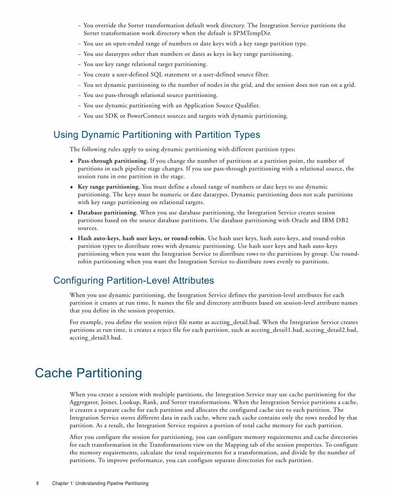
− You override the Sorter transformation default work directory. The Integration Service partitions the Sorter transformation work directory when the default is $PMTempDir.
− You use an open-ended range of numbers or date keys with a key range partition type.
− You use datatypes other than numbers or dates as keys in key range partitioning.
− You use key range relational target partitioning.
− You create a user-defined SQL statement or a user-defined source filter.
− You set dynamic partitioning to the number of nodes in the grid, and the session does not run on a grid.
− You use pass-through relational source partitioning.
− You use dynamic partitioning with an Application Source Qualifier.
− You use SDK or PowerConnect sources and targets with dynamic partitioning.
Using Dynamic Partitioning with Partition TypesThe following rules apply to using dynamic partitioning with different partition types:
♦ Pass-through partitioning. If you change the number of partitions at a partition point, the number of partitions in each pipeline stage changes. If you use pass-through partitioning with a relational source, the session runs in one partition in the stage.
♦ Key range partitioning. You must define a closed range of numbers or date keys to use dynamic partitioning. The keys must be numeric or date datatypes. Dynamic partitioning does not scale partitions with key range partitioning on relational targets.
♦ Database partitioning. When you use database partitioning, the Integration Service creates session partitions based on the source database partitions. Use database partitioning with Oracle and IBM DB2 sources.
♦ Hash auto-keys, hash user keys, or round-robin. Use hash user keys, hash auto-keys, and round-robin partition types to distribute rows with dynamic partitioning. Use hash user keys and hash auto-keys partitioning when you want the Integration Service to distribute rows to the partitions by group. Use round-robin partitioning when you want the Integration Service to distribute rows evenly to partitions.
Configuring Partition-Level AttributesWhen you use dynamic partitioning, the Integration Service defines the partition-level attributes for each partition it creates at run time. It names the file and directory attributes based on session-level attribute names that you define in the session properties.
For example, you define the session reject file name as accting_detail.bad. When the Integration Service creates partitions at run time, it creates a reject file for each partition, such as accting_detail1.bad, accting_detail2.bad, accting_detail3.bad.
Cache PartitioningWhen you create a session with multiple partitions, the Integration Service may use cache partitioning for the Aggregator, Joiner, Lookup, Rank, and Sorter transformations. When the Integration Service partitions a cache, it creates a separate cache for each partition and allocates the configured cache size to each partition. The Integration Service stores different data in each cache, where each cache contains only the rows needed by that partition. As a result, the Integration Service requires a portion of total cache memory for each partition.
After you configure the session for partitioning, you can configure memory requirements and cache directories for each transformation in the Transformations view on the Mapping tab of the session properties. To configure the memory requirements, calculate the total requirements for a transformation, and divide by the number of partitions. To improve performance, you can configure separate directories for each partition.
6 Chapter 1: Understanding Pipeline Partitioning

The following table describes the situations when the Integration Service uses cache partitioning for each applicable transformation:
RELATED TOPICS:♦ “Partitioning Joiner Transformations” on page 26
♦ “Partitioning Lookup Transformations” on page 31
♦ “Session Caches” on page 233
Mapping Variables in Partitioned PipelinesWhen you specify multiple partitions in a target load order group that uses mapping variables, the Integration Service evaluates the value of a mapping variable in each partition separately. The Integration Service uses the following process to evaluate variable values:
1. It updates the current value of the variable separately in each partition according to the variable function used in the mapping.
2. After loading all the targets in a target load order group, the Integration Service combines the current values from each partition into a single final value based on the aggregation type of the variable.
3. If there is more than one target load order group in the session, the final current value of a mapping variable in a target load order group becomes the current value in the next target load order group.
4. When the Integration Service finishes loading the last target load order group, the final current value of the variable is saved into the repository.
Use one of the following variable functions in the mapping to set the variable value:
♦ SetCountVariable
♦ SetMaxVariable
♦ SetMinVariable
The following table describes how the Integration Service calculates variable values across partitions:
Note: Use variable functions only once for each mapping variable in a pipeline. The Integration Service processes variable functions as it encounters them in the mapping. The order in which the Integration Service encounters
Transformation Description
Aggregator Transformation You create multiple partitions in a session with an Aggregator transformation. You do not have to set a partition point at the Aggregator transformation.
Joiner Transformation You create a partition point at the Joiner transformation.
Lookup Transformation You create a hash auto-keys partition point at the Lookup transformation.
Rank Transformation You create multiple partitions in a session with a Rank transformation. You do not have to set a partition point at the Rank transformation.
Sorter Transformation You create multiple partitions in a session with a Sorter transformation. You do not have to set a partition point at the Sorter transformation.
Variable Function Variable Value Calculation Across Partitions
SetCountVariable Integration Service calculates the final count values from all partitions.
SetMaxVariable Integration Service compares the final variable value for each partition and saves the highest value.
SetMinVariable Integration Service compares the final variable value for each partition and saves the lowest value.
Mapping Variables in Partitioned Pipelines 7

variable functions in the mapping may not be the same for every session run. This may cause inconsistent results when you use the same variable function multiple times in a mapping.
Partitioning RulesYou can create multiple partitions in a pipeline if the Integration Service can maintain data consistency when it processes the partitioned data. When you create a session, the Workflow Manager validates each pipeline for partitioning.
Partition Restrictions for Editing ObjectsWhen you edit object properties, you can impact your ability to create multiple partitions in a session or to run an existing session with multiple partitions.
Before You Create a SessionWhen you create a session, the Workflow Manager checks the mapping properties. Mappings dynamically pick up changes to shortcuts, but not to reusable objects, such as reusable transformations and mapplets. Therefore, if you edit a reusable object in the Designer after you save a mapping and before you create a session, you must open and resave the mapping for the Workflow Manager to recognize the changes to the object.
After You Create a Session with Multiple PartitionsWhen you edit a mapping after you create a session with multiple partitions, the Workflow Manager does not invalidate the session even if the changes violate partitioning rules. The Integration Service fails the session the next time it runs unless you edit the session so that it no longer violates partitioning rules.
The following changes to mappings can cause session failure:
♦ You delete a transformation that was a partition point.
♦ You add a transformation that is a default partition point.
♦ You move a transformation that is a partition point to a different pipeline.
♦ You change a transformation that is a partition point in any of the following ways:
− The existing partition type is invalid.
− The transformation can no longer support multiple partitions.
− The transformation is no longer a valid partition point.
♦ You disable partitioning or you change the partitioning between a single node and a grid in a transformation after you create a pipeline with multiple partitions.
♦ You switch the master and detail source for the Joiner transformation after you create a pipeline with multiple partitions.
Partition Restrictions for PowerExchangeYou can specify multiple partitions for PowerExchange and PowerExchange Client for PowerCenter. However, there are additional restrictions. For more information about these products, see the product documentation.
8 Chapter 1: Understanding Pipeline Partitioning

Configuring PartitioningWhen you create or edit a session, you can change the partitioning for each pipeline in a mapping. If the mapping contains multiple pipelines, you can specify multiple partitions in some pipelines and single partitions in others. You update partitioning information using the Partitions view on the Mapping tab of session properties. You can configure partitions for non-reusable sessions in the Workflow Designer and for reusable sessions in the Task Developer.
Add, delete, or edit partition points on the Partitions view of session properties. If you add a key range partition point, you can define the keys in each range.
The following table lists the configuration options for the Partitions view on the Mapping tab:
Adding Partition Points to a PipelineYou add partition points from the Mappings tab of the session properties.
To add a partition point:
1. On the Partitions view of the Mapping tab, select a transformation that is not already a partition point, and click the Add a Partition Point button.
Tip: You can select a transformation from the Non-Partition Points node.
Partitions View Option Description
Add Partition Point Click to add a new partition point. When you add a partition point, the transformation name appears under the Partition Points node.
Delete Partition Point Click to delete the selected partition point.You cannot delete certain partition points.
Edit Partition Point Click to edit the selected partition point. This opens the Edit Partition Point dialog box. For information about the options in this dialog box, see Table 1-1 on page 10.
Key Range Displays the key and key ranges for the partition point, depending on the partition type. For key range partitioning, specify the key ranges.For hash user keys partitioning, this field displays the partition key.The Workflow Manager does not display this area for other partition types.
Edit Keys Click to add or remove the partition key for key range or hash user keys partitioning. You cannot create a partition key for hash auto-keys, round-robin, or pass-through partitioning.
Configuring Part it ioning 9

2. Select the partition type for the partition point or accept the default value.
3. Click OK.
The transformation appears in the Partition Points node in the Partitions view on the Mapping tab of the session properties.
Configuring a Partition PointYou can perform the following tasks when you edit or add a partition point:
♦ Specify the partition type at the partition point.
♦ Add and delete partitions.
♦ Enter a description for each partition.
The following figure shows the configuration options where you edit partition points:
Table 1-1 describes the configuration options for partition points:
You can enter a description for each partition you create. To enter a description, select the partition in the Edit Partition Point dialog box, and then enter the description in the Description field.
Table 1-1. Edit Partition Point Dialog Box Options
Partition Options Description
Select Partition Type Changes the partition type.
Partition Names Selects individual partitions from this dialog box to configure.
Add a Partition Adds a partition. You can add up to 64 partitions at any partition point. The number of partitions must be consistent across the pipeline. Therefore, if you define three partitions at one partition point, the Workflow Manager defines three partitions at all partition points in the pipeline.
Delete a Partition Deletes the selected partition. Each partition point must contain at least one partition.
Description Enter an optional description for the current partition.
Selected Partition PointAdd a partition.
Select a partition.
Delete a partition.
Specify the partition type.
Enter the partition description.
10 Chapter 1: Understanding Pipeline Partitioning

Partition Points NodeThe Partition Points node displays the mapping with the transformation icons. The Partition Points node lists the partition points in the tree. Select a partition point to configure its attributes.
In the Partition Points node, you can configure the following options for each pipeline in a mapping:
♦ Add and delete partition points.
♦ Specify the partition type at each partition point.
♦ Add and delete partitions.
♦ Enter a description for each partition.
♦ Add keys and key ranges for certain partition types.
The following table describes the Partition Points node:
Edit Partition PointThe Edit Partition Point dialog box lets you add and delete partitions and select the partition type.
The following table describes the options in the Edit Partition Point dialog box:
Edit Partition KeyWhen you specify key range or hash user keys partitioning at any partition point, you must specify one or more ports as the partition key. Click Edit Key to display the Edit Partition Key dialog box.
You can specify one or more ports as the partition key. To rearrange the order of the ports that make up the key, select a port in the Selected Ports list and click the up or down arrow.
RELATED TOPICS:♦ “Database Partitioning Partition Type” on page 38
♦ “Key Range Partition Type” on page 42
Non-Partition Points NodeThe Non-Partition Points node displays the mapping objects in iconized view. The Partition Points node lists the non-partition points in the tree. You can select a non-partition point and add partitions if you want.
Partition Points Node Description
Add Partition Point Click to add a new partition point to the Transformation list.
Delete Partition Point
Click to delete the current partition point. You cannot delete certain partition points.
Edit Partition Point Click to edit the current partition point.
Edit Keys Click to add, remove, or edit the key for key range or hash user keys partitioning. This button is not available for auto-hash, round-robin, or pass-through partitioning.
Edit Partition Point Options Description
Add button Click to add a partition. You can add up to 64 partitions.
Delete button Click to delete the selected partition.
Name Partition number.
Description Enter a description for the current partition.
Select Partition Type Select a partition type from the list.
Configuring Part it ioning 11

12 Chapter 1: Understanding Pipeline Partitioning

C H A P T E R 2
Partition Points
This chapter includes the following topics:
♦ Overview, 13
♦ Adding and Deleting Partition Points, 14
♦ Partitioning Relational Sources, 16
♦ Partitioning File Sources, 17
♦ Partitioning Relational Targets, 21
♦ Partitioning File Targets, 22
♦ Partitioning Custom Transformations, 24
♦ Partitioning Joiner Transformations, 26
♦ Partitioning Lookup Transformations, 31
♦ Partitioning Sequence Generator Transformations, 33
♦ Partitioning Sorter Transformations, 33
♦ Partitioning XML Generator Transformations, 33
♦ Restrictions for Transformations, 33
OverviewPartition points mark the boundaries between threads in a pipeline. The Integration Service redistributes rows of data at partition points. You can add partition points to increase the number of transformation threads and increase session performance. For information about adding and deleting partition points, see “Adding and Deleting Partition Points” on page 14.
When you configure a session to read a source database, the Integration Service creates a separate connection and SQL query to the source database for each partition. You can customize or override the SQL query. For more information about partitioning relational sources, see “Partitioning Relational Sources” on page 16.
When you configure a session to load data to a relational target, the Integration Service creates a separate connection to the target database for each partition at the target instance. You configure the reject file names and directories for the target. The Integration Service creates one reject file for each target partition. For more information about partitioning relational targets, see “Partitioning Relational Targets” on page 21.
You can configure a session to read a source file with one thread or with multiple threads. You must choose the same connection type for all partitions that read the file. For more information about partitioning source files, see “Partitioning File Sources” on page 17.
When you configure a session to write to a file target, you can write the target output to a separate file for each partition or to a merge file that contains the target output for all partitions. You can configure connection
Overview 13

settings and file properties for each target partition. For more information about configuring target files, see “Partitioning File Targets” on page 22.
When you create a partition point at transformations, the Workflow Manager sets the default partition type. You can change the partition type depending on the transformation type.
Adding and Deleting Partition PointsPartition points mark the thread boundaries in a pipeline and divide the pipeline into stages. When you add partition points, you increase the number of transformation threads, which can improve session performance. The Integration Service can redistribute rows of data at partition points, which can also improve session performance.
When you create a session, the Workflow Manager creates one partition point at each transformation in the pipeline.
The following table lists the transformations with partition points:
Rules and Guidelines Use the following rules and guidelines apply when adding and deleting partition points:
♦ You cannot create a partition point at a source instance.
♦ You cannot create a partition point at a Sequence Generator transformation or an unconnected transformation.
♦ You can add a partition point at any other transformation provided that no partition point receives input from more than one pipeline stage.
Partition Point Description Restrictions
Source Qualifier Normalizer
Controls how the Integration Service extracts data from the source and passes it to the source qualifier.
You cannot delete this partition point.
Rank Unsorted Aggregator
Ensures that the Integration Service groups rows properly before it sends them to the transformation.
You can delete these partition points if the pipeline contains only one partition or if the Integration Service passes all rows in a group to a single partition before they enter the transformation.
Target Instances Controls how the writer passes data to the targets
You cannot delete this partition point.
Multiple Input Group The Workflow Manager creates a partition point at a multiple input group transformation when it is configured to process each partition with one thread, or when a downstream multiple input group Custom transformation is configured to process each partition with one thread.For example, the Workflow Manager creates a partition point at a Joiner transformation that is connected to a downstream Custom transformation configured to use one thread per partition.This ensures that the Integration Service uses one thread to process each partition at a Custom transformation that requires one thread per partition. You cannot delete this partition point.
You cannot delete this partition point.
14 Chapter 2: Partition Points

♦ You cannot delete a partition point at a Source Qualifier transformation, a Normalizer transformation for COBOL sources, or a target instance.
♦ You cannot delete a partition point at a multiple input group Custom transformation that is configured to use one thread per partition.
♦ You cannot delete a partition point at a multiple input group transformation that is upstream from a multiple input group Custom transformation that is configured to use one thread per partition.
♦ The following partition types have restrictions with dynamic partitioning:
− Pass-through. When you use dynamic partitioning, if you change the number of partitions at a partition point, the number of partitions in each pipeline stage changes.
− Key Range. To use key range with dynamic partitioning you must define a closed range of numbers or date keys. If you use an open-ended range, the session runs with one partition.
You can add and delete partition points at other transformations in the pipeline according to the following rules:
♦ You cannot create partition points at source instances.
♦ You cannot create partition points at Sequence Generator transformations or unconnected transformations.
♦ You can add partition points at any other transformation provided that no partition point receives input from more than one pipeline stage.
The following figure shows the valid partition points in a mapping:
In this mapping, the Workflow Manager creates partition points at the source qualifier and target instance by default. You can place an additional partition point at Expression transformation EXP_3.
If you place a partition point at EXP_3 and define one partition, the master thread creates the following threads:
In this case, each partition point receives data from only one pipeline stage, so EXP_3 is a valid partition point.
Valid Partition Points*
** *
Partition Points*
** *
Reader Thread Transformation Threads Writer Thread(Fourth Stage)(Third Stage)(Second Stage)(First Stage)
Adding and Deleting Part it ion Points 15

The following transformations are not valid partition points:
Partitioning Relational SourcesWhen you run a session that partitions relational or Application sources, the Integration Service creates a separate connection to the source database for each partition. It then creates an SQL query for each partition. You can customize the query for each source partition by entering filter conditions in the Transformation view on the Mapping tab. You can also override the SQL query for each source partition using the Transformations view on the Mapping tab.
Note: When you create a custom SQL query to read database tables and you set database partitioning, the Integration Service reverts to pass-through partitioning and prints a message in the session log.
Entering an SQL QueryYou can enter an SQL override if you want to customize the SELECT statement in the SQL query. The SQL statement you enter on the Transformations view of the Mapping tab overrides any customized SQL query that you set in the Designer when you configure the Source Qualifier transformation.
The SQL query also overrides any key range and filter condition that you enter for a source partition. So, if you also enter a key range and source filter, the Integration Service uses the SQL query override to extract source data.
If you create a key that contains null values, you can extract the nulls by creating another partition and entering an SQL query or filter to extract null values.
To enter an SQL query for each partition, click the Browse button in the SQL Query field. Enter the query in the SQL Editor dialog box, and then click OK.
If you entered an SQL query in the Designer when you configured the Source Qualifier transformation, that query appears in the SQL Query field for each partition. To override this query, click the Browse button in the SQL Query field, revise the query in the SQL Editor dialog box, and then click OK.
Entering a Filter ConditionIf you specify key range partitioning at a relational source qualifier, you can enter an additional filter condition. When you do this, the Integration Service generates a WHERE clause that includes the filter condition you enter in the session properties.
The filter condition you enter on the Transformations view of the Mapping tab overrides any filter condition that you set in the Designer when you configure the Source Qualifier transformation.
Transformation Reason
Source Source instance.
SG_1 Sequence Generator transformation.
EXP_1 and EXP_2 If you could place a partition point at EXP_1 or EXP_2, you would create an additional pipeline stage that processes data from the source qualifier to EXP_1 or EXP_2. In this case, EXP_3 would receive data from two pipeline stages, which is not allowed.
16 Chapter 2: Partition Points

If you use key range partitioning, the filter condition works in conjunction with the key ranges. For example, you want to select data based on customer ID, but you do not want to extract information for customers outside the USA. Define the following key ranges:
If you know that the IDs for customers outside the USA fall within the range for a particular partition, you can enter a filter in that partition to exclude them. Therefore, you enter the following filter condition for the second partition:
CUSTOMERS.COUNTRY = ‘USA’
When the session runs, the following queries for the two partitions appear in the session log:
READER_1_1_1> RR_4010 SQ instance [SQ_CUSTOMERS] SQL Query [SELECT CUSTOMERS.CUSTOMER_ID, CUSTOMERS.COMPANY, CUSTOMERS.LAST_NAME FROM CUSTOMERS WHERE CUSTOMER.CUSTOMER ID < 135000] [...] READER_1_1_2> RR_4010 SQ instance [SQ_CUSTOMERS] SQL Query [SELECT CUSTOMERS.CUSTOMER_ID, CUSTOMERS.COMPANY, CUSTOMERS.LAST_NAME FROM CUSTOMERS WHERE CUSTOMERS.COUNTRY = ‘USA’ AND 135000 <= CUSTOMERS.CUSTOMER_ID]
To enter a filter condition, click the Browse button in the Source Filter field. Enter the filter condition in the SQL Editor dialog box, and then click OK.
If you entered a filter condition in the Designer when you configured the Source Qualifier transformation, that query appears in the Source Filter field for each partition. To override this filter, click the Browse button in the Source Filter field, change the filter condition in the SQL Editor dialog box, and then click OK.
Partitioning File SourcesWhen a session uses a file source, you can configure it to read the source with one thread or with multiple threads. The Integration Service creates one connection to the file source when you configure the session to read with one thread, and it creates multiple concurrent connections to the file source when you configure the session to read with multiple threads.
Use the following types of partitioned file sources:
♦ Flat file. You can configure a session to read flat file, XML, or COBOL source files.
♦ Command. You can configure a session to use an operating system command to generate source data rows or generate a file list.
When connecting to file sources, you must choose the same connection type for all partitions. You may choose different connection objects as long as each object is of the same type.
To specify single- or multi-threaded reading for flat file sources, configure the source file name property for partitions 2-n. To configure for single-threaded reading, pass empty data through partitions 2-n. To configure for multi-threaded reading, leave the source file name blank for partitions 2-n.
Rules and Guidelines for Partitioning File SourcesUse the following rules and guidelines when you configure a file source session with multiple partitions:
♦ Use pass-through partitioning at the source qualifier.
♦ Use single- or multi-threaded reading with flat file or COBOL sources.
♦ Use single-threaded reading with XML sources.
CUSTOMER_ID Start Range End Range
Partition #1 135000
Partition #2 135000
Partitioning File Sources 17

♦ You cannot use multi-threaded reading if the source files are non-disk files, such as FTP files or WebSphere MQ sources.
♦ If you use a shift-sensitive code page, use multi-threaded reading if the following conditions are true:
− The file is fixed-width.
− The file is not line sequential.
− You did not enable user-defined shift state in the source definition.
♦ To read data from the three flat files concurrently, you must specify three partitions at the source qualifier. Accept the default partition type, pass-through.
♦ If you configure a session for multi-threaded reading, and the Integration Service cannot create multiple threads to a file source, it writes a message to the session log and reads the source with one thread.
♦ When the Integration Service uses multiple threads to read a source file, it may not read the rows in the file sequentially. If sort order is important, configure the session to read the file with a single thread. For example, sort order may be important if the mapping contains a sorted Joiner transformation and the file source is the sort origin.
♦ You can also use a combination of direct and indirect files to balance the load.
♦ Session performance for multi-threaded reading is optimal with large source files. The load may be unbalanced if the amount of input data is small.
♦ You cannot use a command for a file source if the command generates source data and the session is configured to run on a grid or is configured with the resume from the last checkpoint recovery strategy.
Using One Thread to Read a File SourceWhen the Integration Service uses one thread to read a file source, it creates one connection to the source. The Integration Service reads the rows in the file or file list sequentially. You can configure single-threaded reading for direct or indirect file sources in a session:
♦ Reading direct files. You can configure the Integration Service to read from one or more direct files. If you configure the session with more than one direct file, the Integration Service creates a concurrent connection to each file. It does not create multiple connections to a file.
♦ Reading indirect files. When the Integration Service reads an indirect file, it reads the file list and then reads the files in the list sequentially. If the session has more than one file list, the Integration Service reads the file lists concurrently, and it reads the files in the list sequentially.
Using Multiple Threads to Read a File SourceWhen the Integration Service uses multiple threads to read a source file, it creates multiple concurrent connections to the source. The Integration Service may or may not read the rows in a file sequentially.
You can configure multi-threaded reading for direct or indirect file sources in a session:
♦ Reading direct files. When the Integration Service reads a direct file, it creates multiple reader threads to read the file concurrently. You can configure the Integration Service to read from one or more direct files. For example, if a session reads from two files and you create five partitions, the Integration Service may distribute one file between two partitions and one file between three partitions.
♦ Reading indirect files. When the Integration Service reads an indirect file, it creates multiple threads to read the file list concurrently. It also creates multiple threads to read the files in the list concurrently. The Integration Service may use more than one thread to read a single file.
Configuring for File PartitioningAfter you create partition points and configure partitioning information, you can configure source connection settings and file properties on the Transformations view of the Mapping tab. Click the source instance name you want to configure under the Sources node. When you click the source instance name for a file source, the Workflow Manager displays connection and file properties in the session properties.
18 Chapter 2: Partition Points

You can configure the source file names and directories for each source partition. The Workflow Manager generates a file name and location for each partition.
The following table describes the file properties settings for file sources in a mapping:
Configuring Sessions to Use a Single ThreadTo configure a session to read a file with a single thread, pass empty data through partitions 2-n. To pass empty data, create a file with no data, such as “empty.txt,” and put it in the source file directory. Then, use “empty.txt” as the source file name.
Note: You cannot configure single-threaded reading for partitioned sources that use a command to generate source data.
Attribute Description
Input Type Type of source input. You can choose the following types of source input:- File. For flat file, COBOL, or XML sources. - Command. For source data or a file list generated by a command.You cannot use a command to generate XML source data.
Concurrent read partitioning
Order in which multiple partitions read input rows from a source file. You can choose the following options:- Optimize throughput. The Integration Service does not preserve input row order.- Keep relative input row order. The Integration Service preserves the input row order for
the rows read by each partition.- Keep absolute input row order. The Integration Service preserves the input row order
for all rows read by all partitions.
Source File Directory
Directory name of flat file source. By default, the Integration Service looks in the service process variable directory, $PMSourceFileDir, for file sources.If you specify both the directory and file name in the Source Filename field, clear this field. The Integration Service concatenates this field with the Source Filename field when it runs the session.You can also use the $InputFileName session parameter to specify the file location.
Source File Name File name, or file name and path of flat file source. Optionally, use the $InputFileName session parameter for the file name.The Integration Service concatenates this field with the Source File Directory field when it runs the session. For example, if you have “C:\data\” in the Source File Directory field, then enter “filename.dat” in the Source Filename field. When the Integration Service begins the session, it looks for “C:\data\filename.dat”. By default, the Workflow Manager enters the file name configured in the source definition.
Source File Type You can choose the following source file types:- Direct. For source files that contain the source data. - Indirect. For source files that contain a list of files. When you select Indirect, the
Integration Service finds the file list and reads each listed file when it runs the session.
Command Type Type of source data the command generates. You can choose the following command types:- Command generating data for commands that generate source data input rows.- Command generating file list for commands that generate a file list.
Command Command used to generate the source file data.
Partitioning File Sources 19

The following table describes the session configuration and the Integration Service behavior when it uses a single thread to read source files:
If you use FTP to access source files, you can choose a different connection for each direct file.
RELATED TOPICS:♦ “FTP” on page 227
Configuring Sessions to Use Multiple ThreadsTo configure a session to read a file with multiple threads, leave the source file name blank for partitions 2-n. The Integration Service uses partitions 2-n to read a portion of the previous partition file or file list. The Integration Service ignores the directory field of that partition.
To configure a session to read from a command with multiple threads, enter a command for each partition or leave the command property blank for partitions 2-n. If you enter a command for each partition, the Integration Service creates a thread to read the data generated by each command. Otherwise, the Integration Service uses partitions 2-n to read a portion of the data generated by the command for the first partition.
The following table describes the session configuration and the Integration Service behavior when it uses multiple threads to read source files:
The following table describes the session configuration and the Integration Service behavior when it uses multiple threads to read source data piped from a command:
Configuring Concurrent Read PartitioningBy default, the Integration Service does not preserve row order when multiple partitions read from a single file source. To preserve row order when multiple partitions read from a single file source, configure concurrent read partitioning. You can configure the following options:
Source File Name Value Integration Service Behavior
Partition #1Partition #2Partition #3
ProductsA.txtempty.txtempty.txt
Integration Service creates one thread to read ProductsA.txt. It reads rows in the file sequentially. After it reads the file, it passes the data to three partitions in the transformation pipeline.
Partition #1Partition #2Partition #3
ProductsA.txtempty.txtProductsB.txt
Integration Service creates two threads. It creates one thread to read ProductsA.txt, and it creates one thread to read ProductsB.txt. It reads the files concurrently, and it reads rows in the files sequentially.
Attribute Value Integration Service Behavior
Partition #1Partition #2Partition #3
ProductsA.txt<blank><blank>
Integration Service creates three threads to concurrently read ProductsA.txt.
Partition #1Partition #2Partition #3
ProductsA.txt<blank>ProductsB.txt
Integration Service creates three threads to read ProductsA.txt and ProductsB.txt concurrently. Two threads read ProductsA.txt and one thread reads ProductsB.txt.
Attribute Value Integration Service Behavior
Partition #1Partition #2Partition #3
CommandA<blank><blank>
Integration Service creates three threads to concurrently read data piped from the command.
Partition #1Partition #2Partition #3
CommandA<blank>CommandB
Integration Service creates three threads to read data piped from CommandA and CommandB. Two threads read the data piped from CommandA and one thread reads the data piped from CommandB.
20 Chapter 2: Partition Points

♦ Optimize throughput. The Integration Service does not preserve row order when multiple partitions read from a single file source. Use this option if the order in which multiple partitions read from a file source is not important.
♦ Keep relative input row order. Preserves the sort order of the input rows read by each partition. Use this option if you want to preserve the sort order of the input rows read by each partition.
The following table shows an example sort order of a file source with 10 rows by two partitions:
♦ Keep absolute input row order. Preserves the sort order of all input rows read by all partitions. Use this option if you want to preserve the sort order of the input rows each time the session runs. In a pass-through mapping with passive transformations, the order of the rows written to the target will be in the same order as the input rows.
The following table shows an example sort order of a file source with 10 rows by two partitions:
Note: By default, the Integration Service uses the Keep absolute input row order option in sessions configured with the resume from the last checkpoint recovery strategy.
Partitioning Relational TargetsWhen you configure a pipeline to load data to a relational target, the Integration Service creates a separate connection to the target database for each partition at the target instance. It concurrently loads data for each partition into the target database.
Configure partition attributes for targets in the pipeline on the Mapping tab of session properties. For relational targets, you configure the reject file names and directories. The Integration Service creates one reject file for each target partition.
The following table describes the partitioning attributes for relational targets in a pipeline:
Database CompatibilityWhen you configure a session with multiple partitions at the target instance, the Integration Service creates one connection to the target for each partition. If you configure multiple target partitions in a session that loads to a database or ODBC target that does not support multiple concurrent connections to tables, the session fails.
When you create multiple target partitions in a session that loads data to an Informix database, you must create the target table with row-level locking. If you insert data from a session with multiple partitions into an Informix target configured for page-level locking, the session fails and returns the following message:
Partition Rows Read
Partition #1 1,3,5,8,9
Partition #2 2,4,6,7,10
Partition Rows Read
Partition #1 1,2,3,4,5
Partition #2 6,7,8,9,10
Attribute Description
Reject File Directory Location for the target reject files. Default is $PMBadFileDir.
Reject File Name Name of reject file. Default is target name partition number.bad. You can also use the session parameter, $BadFileName, as defined in the parameter file.
Partitioning Relational Targets 21
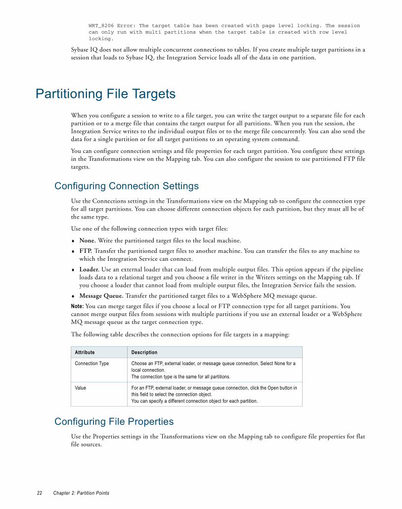
WRT_8206 Error: The target table has been created with page level locking. The session can only run with multi partitions when the target table is created with row level locking.
Sybase IQ does not allow multiple concurrent connections to tables. If you create multiple target partitions in a session that loads to Sybase IQ, the Integration Service loads all of the data in one partition.
Partitioning File TargetsWhen you configure a session to write to a file target, you can write the target output to a separate file for each partition or to a merge file that contains the target output for all partitions. When you run the session, the Integration Service writes to the individual output files or to the merge file concurrently. You can also send the data for a single partition or for all target partitions to an operating system command.
You can configure connection settings and file properties for each target partition. You configure these settings in the Transformations view on the Mapping tab. You can also configure the session to use partitioned FTP file targets.
Configuring Connection SettingsUse the Connections settings in the Transformations view on the Mapping tab to configure the connection type for all target partitions. You can choose different connection objects for each partition, but they must all be of the same type.
Use one of the following connection types with target files:
♦ None. Write the partitioned target files to the local machine.
♦ FTP. Transfer the partitioned target files to another machine. You can transfer the files to any machine to which the Integration Service can connect.
♦ Loader. Use an external loader that can load from multiple output files. This option appears if the pipeline loads data to a relational target and you choose a file writer in the Writers settings on the Mapping tab. If you choose a loader that cannot load from multiple output files, the Integration Service fails the session.
♦ Message Queue. Transfer the partitioned target files to a WebSphere MQ message queue.
Note: You can merge target files if you choose a local or FTP connection type for all target partitions. You cannot merge output files from sessions with multiple partitions if you use an external loader or a WebSphere MQ message queue as the target connection type.
The following table describes the connection options for file targets in a mapping:
Configuring File PropertiesUse the Properties settings in the Transformations view on the Mapping tab to configure file properties for flat file sources.
Attribute Description
Connection Type Choose an FTP, external loader, or message queue connection. Select None for a local connection.The connection type is the same for all partitions.
Value For an FTP, external loader, or message queue connection, click the Open button in this field to select the connection object.You can specify a different connection object for each partition.
22 Chapter 2: Partition Points

The following table describes the file properties for file targets in a mapping:
Configuring Commands for Partitioned File TargetsUse a command to process target data for a single partition or process merge data for all target partitions in a session. On UNIX, use any valid UNIX command or shell script. On Windows, use any valid DOS or batch file. The Integration Service sends the data to a command instead of a flat file target or merge file.
Use a command to process the following types of target data:
♦ Target data for a single partition. You can enter a command for each target partition. The Integration Service sends the target data to the command when the session runs.
To send the target data for a single partition to a command, select Command for the Output Type. Enter a command for the Command property for the partition in the session properties.
♦ Merge data for all target partitions. You can enter a command to process the merge data for all partitions. The Integration Service concurrently sends the target data for all partitions to the command when the session runs. The command may not maintain the order of the target data.
To send merge data for all partitions to a command, select Command as the Output Type and enter a command for the Merge Command Line property in the session properties.
Configuring Merge OptionsYou can merge target data for the partitions in a session. When you merge target data, the Integration Service creates a merge file for all target partitions.
You can configure the following merge file options:
Attribute Description
Merge Type Type of merge the Integration Service performs on the data for partitioned targets. When merging target files, the Integration Service writes the output for all partitions to the merge file or a command when the session runs. You cannot merge files if the session uses an external loader or a message queue.
Merge File Directory Location of the merge file. Default is $PMTargetFileDir.
Merge File Name Name of the merge file. Default is target name.out.
Append if Exists Appends the output data to the target files and reject files for each partition. Appends output data to the merge file if you merge the target files. You cannot use this option for target files that are non-disk files, such as FTP target files.If you do not select this option, the Integration Service truncates each target file before writing the output data to the target file. If the file does not exist, the Integration Service creates it.
Output Type Type of target for the session. Select File to write the target data to a file target. Select Command to send target data to a command. You cannot select Command for FTP or queue target connection.
Header Options Create a header row in the file target.
Header Command Command used to generate the header row in the file target.
Footer Command Command used to generate a footer row in the file target.
Merge Command Command used to process merged target data.
Output File Directory Location of the target file. Default is $PMTargetFileDir.
Output File Name Name of target file. Default is target name partition number.out. You can also use the session parameter, $OutputFileName, as defined in the parameter file.
Reject File Directory Location for the target reject files. Default is $PMBadFileDir.
Reject File Name Name of reject file. Default is target name partition number.bad. You can also use the session parameter, $BadFileName, as defined in the parameter file.
Command Command used to process the target output data for a single partition.
Part it ioning File Targets 23

♦ Sequential Merge. The Integration Service creates an output file for all partitions and then merges them into a single merge file at the end of the session. The Integration Service sequentially adds the output data for each partition to the merge file. The Integration Service creates the individual target file using the Output File Name and Output File Directory values for the partition.
♦ File list. The Integration Service creates a target file for all partitions and creates a file list that contains the paths of the individual files. The Integration Service creates the individual target file using the Output File Name and Output File Directory values for the partition. If you write the target files to the merge directory or a directory under the merge directory, the file list contains relative paths. Otherwise, the list file contains absolute paths. Use this file as a source file if you use the target files as source files in another mapping.
♦ Concurrent Merge. The Integration Service concurrently writes the data for all target partitions to the merge file. It does not create intermediate files for each partition. Since the Integration Service writes to the merge file concurrently for all partitions, the sort order of the data in the merge file may not be sequential.
For more information about merging target files in sessions that use an FTP connection, see “Configuring FTP in a Session” on page 229.
Partitioning Custom TransformationsWhen a mapping contains a Custom transformation, a Java transformation, SQL transformation, or an HTTP transformation, you can edit the following partitioning information:
♦ Add multiple partitions. You can create multiple partitions when the Custom transformation allows multiple partitions. For more information, see “Working with Multiple Partitions” on page 24.
♦ Create partition points. You can create a partition point at a Custom transformation even when the transformation does not allow multiple partitions. For more information, see “Creating Partition Points” on page 25.
The Java, SQL, and HTTP transformations were built using the Custom transformation and have the same partitioning features. Not all transformations created using the Custom transformation have the same partitioning features as the Custom transformation.
When you configure a Custom transformation to process each partition with one thread, the Workflow Manager adds partition points depending on the mapping configuration. For more information, see “Working with Threads” on page 25.
Working with Multiple PartitionsYou can configure a Custom transformation to allow multiple partitions in mappings. You can add partitions to the pipeline if you set the Is Partitionable property for the transformation. You can select the following values for the Is Partitionable option:
♦ No. The transformation cannot be partitioned. The transformation and other transformations in the same pipeline are limited to one partition. You might choose No if the transformation processes all the input data together, such as data cleansing.
♦ Locally. The transformation can be partitioned, but the Integration Service must run all partitions in the pipeline on the same node. Choose Local when different partitions of the transformation must share objects in memory.
♦ Across Grid. The transformation can be partitioned, and the Integration Service can distribute each partition to different nodes.
Note: When you add multiple partitions to a mapping that includes a multiple input or output group Custom transformation, you define the same number of partitions for all groups.
24 Chapter 2: Partition Points

Creating Partition PointsYou can create a partition point at a Custom transformation even when the transformation does not allow multiple partitions. Use the following rules and guidelines when you create a partition point at a Custom transformation:
♦ You can define the partition type for each input group in the transformation. You cannot define the partition type for output groups.
♦ Valid partition types are pass-through, round-robin, key range, and hash user keys.
Working with ThreadsTo configure a Custom transformation so the Integration Service uses one thread to process the transformation for each partition, enable Requires Single Thread Per Partition Custom transformation property. The Workflow Manager creates a pass-through partition point based on the number of input groups and the location of the Custom transformation in the mapping.
One Input GroupWhen a single input group Custom transformation is downstream from a multiple input group Custom transformation that does not have a partition point, the Workflow Manager places a pass-through partition point at the closest upstream multiple input group transformation.
For example, consider the following mapping:
CT_quartile contains one input group and is downstream from a multiple input group transformation. CT_quartile requires one thread for each partition, but the upstream Custom transformation does not. The Workflow Manager creates a partition point at the closest upstream multiple input group transformation, CT_Sort.
Multiple Input GroupsThe Workflow Manager places a partition point at a multiple input group Custom transformation that requires a single thread for each partition.
For example, consider the following mapping:
*
* Partition Point
Requires one thread for each partition.
Does not require one thread for each partition.
Single Input Group
Multiple Input Groups
Part it ioning Custom Transformations 25

CT_Order_class and CT_Order_Prep have multiple input groups, but only CT_Order_Prep requires one thread for each partition. The Workflow Manager creates a partition point at CT_Order_Prep.
Partitioning Joiner TransformationsWhen you create a partition point at the Joiner transformation, the Workflow Manager sets the partition type to hash auto-keys when the transformation scope is All Input. The Workflow Manager sets the partition type to pass-through when the transformation scope is Transaction.
You must create the same number of partitions for the master and detail source. If you configure the Joiner transformation for sorted input, you can change the partition type to pass-through. You can specify only one partition if the pipeline contains the master source for a Joiner transformation and you do not add a partition point at the Joiner transformation.
The Integration Service uses cache partitioning when you create a partition point at the Joiner transformation. When you use partitioning with a Joiner transformation, you can create multiple partitions for the master and detail source of a Joiner transformation.
If you do not create a partition point at the Joiner transformation, you can create n partitions for the detail source, and one partition for the master source (1:n).
Note: You cannot add a partition point at the Joiner transformation when you configure the Joiner transformation to use the row transformation scope.
Partitioning Sorted Joiner TransformationsWhen you include a Joiner transformation that uses sorted input, you must verify the Joiner transformation receives sorted data. If the sources contain large amounts of data, you may want to configure partitioning to improve performance. However, partitions that redistribute rows can rearrange the order of sorted data, so it is important to configure partitions to maintain sorted data.
For example, when you use a hash auto-keys partition point, the Integration Service uses a hash function to determine the best way to distribute the data among the partitions. However, it does not maintain the sort order, so you must follow specific partitioning guidelines to use this type of partition point.
When you join data, you can partition data for the master and detail pipelines in the following ways:
♦ 1:n. Use one partition for the master source and multiple partitions for the detail source. The Integration Service maintains the sort order because it does not redistribute master data among partitions.
♦ n:n. Use an equal number of partitions for the master and detail sources. When you use n:n partitions, the Integration Service processes multiple partitions concurrently. You may need to configure the partitions to maintain the sort order depending on the type of partition you use at the Joiner transformation.
*
* Partition Point Requires one thread for each partition.
Does not require one thread for each partition.
Multiple Input Groups
26 Chapter 2: Partition Points
Note: When you use 1:n partitions, do not add a partition point at the Joiner transformation. If you add a partition point at the Joiner transformation, the Workflow Manager adds an equal number of partitions to both master and detail pipelines.
Use different partitioning guidelines, depending on where you sort the data:
♦ Using sorted flat files. Use one of the following partitioning configurations:
− Use 1:n partitions when you have one flat file in the master pipeline and multiple flat files in the detail pipeline. Configure the session to use one reader-thread for each file.
− Use n:n partitions when you have one large flat file in the master and detail pipelines. Configure partitions to pass all sorted data in the first partition, and pass empty file data in the other partitions.
♦ Using sorted relational data. Use one of the following partitioning configurations:
− Use 1:n partitions for the master and detail pipeline.
− Use n:n partitions. If you use a hash auto-keys partition, configure partitions to pass all sorted data in the first partition.
♦ Using the Sorter transformation. Use n:n partitions. If you use a hash auto-keys partition at the Joiner transformation, configure each Sorter transformation to use hash auto-keys partition points as well.
Add only pass-through partition points between the sort origin and the Joiner transformation.
Using Sorted Flat FilesUse 1:n partitions when you have one flat file in the master pipeline and multiple flat files in the detail pipeline. When you use 1:n partitions, the Integration Service maintains the sort order because it does not redistribute data among partitions. When you have one large flat file in each master and detail pipeline, use n:n partitions and add a pass-through or hash auto-keys partition at the Joiner transformation. When you add a hash auto-keys partition point, you must configure partitions to pass all sorted data in the first partition to maintain the sort order.
Using 1:n PartitionsIf the session uses one flat file in the master pipeline and multiple flat files in the detail pipeline, use one partition for the master source and n partitions for the detail file sources (1:n). Add a pass-through partition point at the detail Source Qualifier transformation. Do not add a partition point at the Joiner transformation. The Integration Service maintains the sort order when you create one partition for the master source because it does not redistribute sorted data among partitions.
When you have multiple files in the detail pipeline that have the same structure, pass the files to the Joiner transformation using the following guidelines:
♦ Configure the mapping with one source and one Source Qualifier transformation in each pipeline.
♦ Specify the path and file name for each flat file in the Properties settings of the Transformations view on the Mapping tab of the session properties.
♦ Each file must use the same file properties as configured in the source definition.
♦ The range of sorted data in the flat files can overlap. You do not need to use a unique range of data for each file.
The following figure shows sorted file data joined using 1:n partitioning:
Partitioning Joiner Transformations 27

The Joiner transformation may output unsorted data depending on the join type. If you use a full outer or detail outer join, the Integration Service processes unmatched master rows last, which can result in unsorted data.
Using n:n PartitionsIf the session uses sorted flat file data, use n:n partitions for the master and detail pipelines. You can add a pass-through partition or hash auto-keys partition at the Joiner transformation. If you add a pass-through partition at the Joiner transformation, maintain the sort order in mappings. For more information, see the PowerCenter Transformation Guide.
If you add a hash auto-keys partition point at the Joiner transformation, you can maintain the sort order by passing all sorted data to the Joiner transformation in a single partition. When you pass sorted data in one partition, the Integration Service maintains the sort order when it redistributes data using a hash function.
To allow the Integration Service to pass all sorted data in one partition, configure the session to use the sorted file for the first partition and empty files for the remaining partitions.
The Integration Service redistributes the rows among multiple partitions and joins the sorted data.
The following figure shows sorted file data passed through a single partition to maintain sort order:
This example shows sorted data passed in a single partition to maintain the sort order. The first partition contains sorted file data while all other partitions pass empty file data. At the Joiner transformation, the Integration Service distributes the data among all partitions while maintaining the order of the sorted data.
Source Qualifier
Joiner transformation
Source Qualifier with pass-through partition
Sorted Data
Sorted output depends on join type.
Flat File
Flat File 3
Flat File 1
Flat File 2
Source Qualifier
Joiner transformation with hash auto-keys partition point
Source Qualifier
Sorted Data
No Data
28 Chapter 2: Partition Points

Using Sorted Relational DataWhen you join relational data, use 1:n partitions for the master and detail pipeline. When you use 1:n partitions, you cannot add a partition point at the Joiner transformation. If you use n:n partitions, you can add a pass-through or hash auto-keys partition at the Joiner transformation. If you use a hash auto-keys partition point, you must configure partitions to pass all sorted data in the first partition to maintain sort order.
Using 1:n PartitionsIf the session uses sorted relational data, use one partition for the master source and n partitions for the detail source (1:n). Add a key-range or pass-through partition point at the Source Qualifier transformation. Do not add a partition point at the Joiner transformation. The Integration Service maintains the sort order when you create one partition for the master source because it does not redistribute data among partitions.
The following figure shows sorted relational data with 1:n partitioning:
The Joiner transformation may output unsorted data depending on the join type. If you use a full outer or detail outer join, the Integration Service processes unmatched master rows last, which can result in unsorted data.
Using n:n PartitionsIf the session uses sorted relational data, use n:n partitions for the master and detail pipelines and add a pass-through or hash auto-keys partition point at the Joiner transformation. When you use a pass-through partition at the Joiner transformation, maintain sorted data in mappings. For more information, see the PowerCenter Transformation Guide.
When you use a hash auto-keys partition point, you maintain the sort order by passing all sorted data to the Joiner transformation in a single partition. Add a key-range partition point at the Source Qualifier transformation that contains all source data in the first partition. When you pass sorted data in one partition, the Integration Service redistributes data among multiple partitions using a hash function and joins the sorted data.
The following figure shows sorted relational data passed through a single partition to maintain the sort order:
Source Qualifier transformation
Joiner transformation
Source Qualifier transformation with key-range or pass-through partition point Sorted Data
Relational Source
Relational Source
Unsorted Data
Sorted output depends on join type.
Partitioning Joiner Transformations 29

This example shows sorted relational data passed in a single partition to maintain the sort order. The first partition contains sorted relational data while all other partitions pass empty data. After the Integration Service joins the sorted data, it redistributes data among multiple partitions.
Using Sorter TransformationsIf the session uses the Sorter transformations to sort data, use n:n partitions for the master and detail pipelines. Use a hash auto-keys partition point at the Sorter transformation to group the data. You can add a pass-through or hash auto-keys partition point at the Joiner transformation.
The Integration Service groups data into partitions of the same hash values, and the Sorter transformation sorts the data before passing it to the Joiner transformation. When the Integration Service processes the Joiner transformation configured with a hash auto-keys partition, it maintains the sort order by processing the sorted data using the same partitions it uses to route the data from each Sorter transformation.
The following figure shows Sorter transformations used with hash auto-keys to maintain sort order:
Note: For best performance, use sorted flat files or sorted relational data. You may want to calculate the processing overhead for adding Sorter transformations to the mapping.
Optimizing Sorted Joiner Transformations with PartitionsWhen you use partitions with a sorted Joiner transformation, you may optimize performance by grouping data and using n:n partitions.
Source Qualifier transformation with key-range partition point Joiner
transformation with hash auto-keys partition pointSource Qualifier
transformation with key-range partition point
Sorted Data
No Data
Relational Source
Relational Source
Sorter transformation with hash auto-keys partition point
Joiner transformation with hash auto-keys or pass-through partition pointSorter
transformation with hash auto-keys partition point
Sorted DataUnsorted Data
Source with unsorted data
Source with unsorted data
Source Qualifier transformation
Source Qualifier transformation
30 Chapter 2: Partition Points
Add a Hash Auto-keys Partition Upstream of the Sort OriginTo obtain expected results and get best performance when partitioning a sorted Joiner transformation, you must group and sort data. To group data, ensure that rows with the same key value are routed to the same partition. The best way to ensure that data is grouped and distributed evenly among partitions is to add a hash auto-keys or key-range partition point before the sort origin. Placing the partition point before you sort the data ensures that you maintain grouping and sort the data within each group.
Use n:n PartitionsYou may be able to improve performance for a sorted Joiner transformation by using n:n partitions. When you use n:n partitions, the Joiner transformation reads master and detail rows concurrently and does not need to cache all of the master data. This reduces memory usage and speeds processing. When you use 1:n partitions, the Joiner transformation caches all the data from the master pipeline and writes the cache to disk if the memory cache fills. When the Joiner transformation receives the data from the detail pipeline, it must then read the data from disk to compare the master and detail pipelines.
Partitioning Lookup TransformationsYou can configure cache partitioning for a Lookup transformation. You can create multiple partitions for static and dynamic lookup caches.
The cache for a pipeline Lookup transformation is built in an independent pipeline from the pipeline that contains the Lookup transformation. You can create multiple partitions in both pipelines.
Cache Partitioning Lookup TransformationsUse cache partitioning for static and dynamic caches, and named and unnamed caches. When you create a partition point at a connected Lookup transformation, use cache partitioning under the following conditions:
♦ Use the hash auto-keys partition type for the Lookup transformation.
♦ The lookup condition must contain only equality operators.
♦ The database is configured for case-sensitive comparison.
For example, if the lookup condition contains a string port and the database is not configured for case-sensitive comparison, the Integration Service does not perform cache partitioning and writes the following message to the session log:
CMN_1799 Cache partitioning requires case sensitive string comparisons. Lookup will not use partitioned cache as the database is configured for case insensitive string comparisons.
The Integration Service uses cache partitioning when you create a hash auto-keys partition point at the Lookup transformation.
When the Integration Service creates cache partitions, it begins creating caches for the Lookup transformation when the first row of any partition reaches the Lookup transformation. If you configure the Lookup transformation for concurrent caches, the Integration Service builds all caches for the partitions concurrently.
Sharing Partitioned CachesUse the following guidelines when you share partitioned Lookup caches:
♦ Lookup transformations can share a partitioned cache if the transformations meet the following conditions:
− The cache structures are identical. The lookup/output ports for the first shared transformation must match the lookup/output ports for the subsequent transformations.
Partitioning Lookup Transformations 31
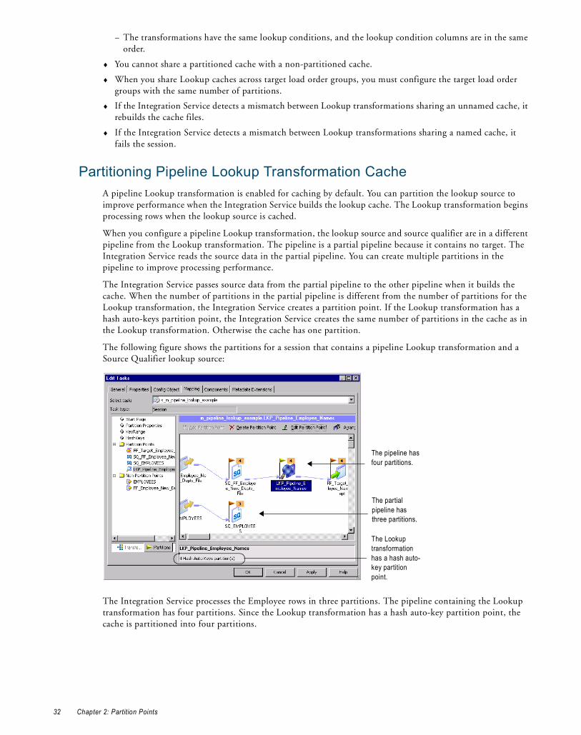
− The transformations have the same lookup conditions, and the lookup condition columns are in the same order.
♦ You cannot share a partitioned cache with a non-partitioned cache.
♦ When you share Lookup caches across target load order groups, you must configure the target load order groups with the same number of partitions.
♦ If the Integration Service detects a mismatch between Lookup transformations sharing an unnamed cache, it rebuilds the cache files.
♦ If the Integration Service detects a mismatch between Lookup transformations sharing a named cache, it fails the session.
Partitioning Pipeline Lookup Transformation CacheA pipeline Lookup transformation is enabled for caching by default. You can partition the lookup source to improve performance when the Integration Service builds the lookup cache. The Lookup transformation begins processing rows when the lookup source is cached.
When you configure a pipeline Lookup transformation, the lookup source and source qualifier are in a different pipeline from the Lookup transformation. The pipeline is a partial pipeline because it contains no target. The Integration Service reads the source data in the partial pipeline. You can create multiple partitions in the pipeline to improve processing performance.
The Integration Service passes source data from the partial pipeline to the other pipeline when it builds the cache. When the number of partitions in the partial pipeline is different from the number of partitions for the Lookup transformation, the Integration Service creates a partition point. If the Lookup transformation has a hash auto-keys partition point, the Integration Service creates the same number of partitions in the cache as in the Lookup transformation. Otherwise the cache has one partition.
The following figure shows the partitions for a session that contains a pipeline Lookup transformation and a Source Qualifier lookup source:
The Integration Service processes the Employee rows in three partitions. The pipeline containing the Lookup transformation has four partitions. Since the Lookup transformation has a hash auto-key partition point, the cache is partitioned into four partitions.
The pipeline has four partitions.
The partial pipeline has three partitions.
The Lookup transformation has a hash auto-key partition point.
32 Chapter 2: Partition Points

Partitioning Sequence Generator TransformationsIf you configure multiple partitions in a session on a grid that uses an uncached Sequence Generator transformation, the sequence numbers the Integration Service generates for each partition are not consecutive.
Partitioning Sorter TransformationsIf you configure multiple partitions in a session that uses a Sorter transformation, the Integration Service sorts data in each partition separately. The Workflow Manager lets you choose hash auto-keys, key-range, or pass-through partitioning when you add a partition point at the Sorter transformation.
Use hash-auto keys partitioning when you place the Sorter transformation before an Aggregator transformation configured to use sorted input. Hash auto-keys partitioning groups rows with the same values into the same partition based on the partition key. After grouping the rows, the Integration Service passes the rows through the Sorter transformation. The Integration Service processes the data in each partition separately, but hash auto-keys partitioning accurately sorts all of the source data because rows with matching values are processed in the same partition. You can delete the default partition point at the Aggregator transformation.
Use key-range partitioning when you want to send all rows in a partitioned session from multiple partitions into a single partition for sorting. When you merge all rows into a single partition for sorting, the Integration Service can process all of the data together.
Use pass-through partitioning if you already used hash partitioning in the pipeline. This ensures that the data passing into the Sorter transformation is correctly grouped among the partitions. Pass-through partitioning increases session performance without increasing the number of partitions in the pipeline.
Configuring Sorter Transformation Work DirectoriesThe Integration Service creates temporary files for each Sorter transformation in a pipeline. It reads and writes data to these files while it performs the sort. The Integration Service stores these files in the Sorter transformation work directories.
By default, the Workflow Manager sets the work directories for all partitions at Sorter transformations to $PMTempDir. You can specify a different work directory for each partition in the session properties.
Partitioning XML Generator TransformationsWhen you generate XML in multiple partitions, you always generate separate documents for each partition. This occurs regardless of the value in the On Commit Flag. If you configure key range partitioning with an XML Generator transformation, a session might fail with orphaned rows in the transformation. This can occur because the XML Generator transformation creates primary-foreign key relationships between rows. Key range partitioning can separate the parent and child rows.
Restrictions for TransformationsSome restrictions on the number of partitions depend on the types of transformations in the pipeline. These restrictions apply to all transformations, including reusable transformations, transformations created in mappings and mapplets, and transformations, mapplets, and mappings referenced by shortcuts.
Partitioning Sequence Generator Transformations 33
The following table describes the restrictions on the number of partitions for transformations:
Sequence numbers generated by Normalizer and Sequence Generator transformations might not be sequential for a partitioned source, but they are unique.
Restrictions for Numerical FunctionsThe numerical functions CUME, MOVINGSUM, and MOVINGAVG calculate running totals and averages on a row-by-row basis. According to the way you partition a pipeline, the order that rows of data pass through a transformation containing one of these functions can change. Therefore, a session with multiple partitions that uses CUME, MOVINGSUM, or MOVINGAVG functions may not always return the same calculated result.
Transformation Restrictions
Custom Transformation By default, you can only specify one partition if the pipeline contains a Custom transformation. However, this transformation contains an option on the Properties tab to allow multiple partitions. If you enable this option, you can specify multiple partitions at this transformation. Do not select Is Partitionable if the Custom transformation procedure performs the procedure based on all the input data together, such as data cleansing.
External Procedure Transformation
By default, you can only specify one partition if the pipeline contains an External Procedure transformation. This transformation contains an option on the Properties tab to allow multiple partitions. If this option is enabled, you can specify multiple partitions at this transformation.
Joiner Transformation Specify only one partition if the pipeline contains the master source for a Joiner transformation and you do not add a partition point at the Joiner transformation.
XML Target Instance Specify only one partition if the pipeline contains XML targets.
34 Chapter 2: Partition Points

C H A P T E R 3
Partition Types
This chapter includes the following topics:
♦ Overview, 35
♦ Setting Partition Types, 37
♦ Database Partitioning Partition Type, 38
♦ Hash Auto-Keys Partition Type, 41
♦ Hash User Keys Partition Type, 42
♦ Key Range Partition Type, 42
♦ Pass-Through Partition Type, 45
♦ Round-Robin Partition Type, 46
OverviewThe Integration Services creates a default partition type at each partition point. If you have the Partitioning option, you can change the partition type. The partition type controls how the Integration Service distributes data among partitions at partition points.
When you configure the partitioning information for a pipeline, you must define a partition type at each partition point in the pipeline. The partition type determines how the Integration Service redistributes data across partition points.
You can define the following partition types in the Workflow Manager:
♦ Database partitioning. The Integration Service queries the IBM DB2 or Oracle system for table partition information. It reads partitioned data from the corresponding nodes in the database. Use database partitioning with Oracle or IBM DB2 source instances on a multi-node tablespace. Use database partitioning with DB2 targets. For more information, see “Database Partitioning Partition Type” on page 38.
♦ Hash partitioning. Use hash partitioning when you want the Integration Service to distribute rows to the partitions by group. For example, you need to sort items by item ID, but you do not know how many items have a particular ID number.
You can use the following types of hash partitioning:
− Hash auto-keys. The Integration Service uses all grouped or sorted ports as a compound partition key. You may need to use hash auto-keys partitioning at Rank, Sorter, and unsorted Aggregator transformations. For more information, see “Hash Auto-Keys Partition Type” on page 41.
35

− Hash user keys. The Integration Service uses a hash function to group rows of data among partitions. You define the number of ports to generate the partition key. “Hash User Keys Partition Type” on page 42.
♦ Key range. You specify one or more ports to form a compound partition key. The Integration Service passes data to each partition depending on the ranges you specify for each port. Use key range partitioning where the sources or targets in the pipeline are partitioned by key range. For more information, see “Key Range Partition Type” on page 42.
♦ Pass-through. The Integration Service passes all rows at one partition point to the next partition point without redistributing them. Choose pass-through partitioning where you want to create an additional pipeline stage to improve performance, but do not want to change the distribution of data across partitions. For more information, see “Pass-Through Partition Type” on page 45.
♦ Round-robin. The Integration Service distributes data evenly among all partitions. Use round-robin partitioning where you want each partition to process approximately the same number of rows. For more information, see “Database Partitioning Partition Type” on page 38.
Setting Partition Types in the PipelineYou can create different partition types at different points in the pipeline.
The following figure shows a mapping where you can create partition types to increase session performance:
This mapping reads data about items and calculates average wholesale costs and prices. The mapping must read item information from three flat files of various sizes, and then filter out discontinued items. It sorts the active items by description, calculates the average prices and wholesale costs, and writes the results to a relational database in which the target tables are partitioned by key range.
You can delete the default partition point at the Aggregator transformation because hash auto-keys partitioning at the Sorter transformation sends all rows that contain items with the same description to the same partition. Therefore, the Aggregator transformation receives data for all items with the same description in one partition and can calculate the average costs and prices for this item correctly.
When you use this mapping in a session, you can increase session performance by defining different partition types at the following partition points in the pipeline:
♦ Source qualifier. To read data from the three flat files concurrently, you must specify three partitions at the source qualifier. Accept the default partition type, pass-through.
♦ Filter transformation. Since the source files vary in size, each partition processes a different amount of data. Set a partition point at the Filter transformation, and choose round-robin partitioning to balance the load going into the Filter transformation.
♦ Sorter transformation. To eliminate overlapping groups in the Sorter and Aggregator transformations, use hash auto-keys partitioning at the Sorter transformation. This causes the Integration Service to group all items with the same description into the same partition before the Sorter and Aggregator transformations process the rows. You can delete the default partition point at the Aggregator transformation.
♦ Target. Since the target tables are partitioned by key range, specify key range partitioning at the target to optimize writing data to the target.
36 Chapter 3: Partition Types

Setting Partition TypesThe Workflow Manager sets a default partition type for each partition point in the pipeline. The Workflow Manager specifies pass-through as the default partition type for all partition points unless the transformation scope for a transformation is All Input. You can change the default type.
For example, at the source qualifier and target instance, the Workflow Manager specifies pass-through partitioning. For Rank and unsorted Aggregator transformations, the Workflow Manager specifies hash auto-keys partitioning when the transformation scope is All Input.
You must specify pass-through partitioning for all transformations that are downstream from a transaction generator or an active source that generates commits and upstream from a target or a transformation with Transaction transformation scope. Also, if you configure the session to use constraint-based loading, you must specify pass-through partitioning for all transformations that are downstream from the last active source.
If workflow recovery is enabled, the Workflow Manager sets the partition type to pass-through unless the partition point is either an Aggregator transformation or a Rank transformation.
You cannot create partition points for the following transformations:
♦ Source definition
♦ Sequence Generator
♦ XML Parser
♦ XML target
♦ Unconnected transformations
Table 3-1 lists valid partition types and the default partition type for different partition points in the pipeline:
Table 3-1. Valid Partition Types for Partition Points
Transformation (Partition Point)
Round- Robin
Hash Auto-Keys
Hash User Keys
Key Range
Pass-Through
Database Partitioning
Source Qualifier (relational sources)
X X X (Oracle, DB2)
Source Qualifier (flat file sources)
X
Web Service Source Qualifier
X
XML Source Qualifier X
Normalizer (COBOL sources)
X
Normalizer(relational)
X X X X
Aggregator (sorted) X
Aggregator (unsorted) X X*
Custom X X X X
Data Masking X X X X
Expression X X X X
External Procedure X X X X
Filter X X X X
HTTP X
Java X X X X
Setting Part it ion Types 37

Database Partitioning Partition TypeYou can optimize session performance by using the database partitioning partition type for source and target databases. When you use source database partitioning, the Integration Service queries the database system for table partition information and fetches data into the session partitions. When you use target database partitioning, the Integration Service loads data into corresponding database partition nodes.
Use database partitioning for Oracle and IBM DB2 sources and IBM DB2 targets. Use any number of pipeline partitions and any number of database partitions. However, you can improve performance when the number of pipeline partitions equals the number of database partitions.
For Oracle sources that use composite partitioning, you can improve performance when the number of pipeline partitions equals the number of database subpartitions. For example, if an Oracle source contains three partitions and two subpartitions for each partition, set the number of pipeline partitions at the source to six.
Partitioning Database SourcesWhen you use source database partitioning, the Integration Service queries the database system catalog for partition information. It distributes the data from the database partitions among the session partitions.
If the session has more partitions than the database, the Integration Service generates SQL for each database partition and redistributes the data to the session partitions at the next partition point.
Joiner X X*
Lookup X X X X X
Rank X X*
Router X X X X
Sorter X X X*
Stored Procedure X X X X
Transaction Control X X X X
Union X X X X
Unstructured Data X X X X
Update Strategy X X X X
Web Service Consumer X
XML Generator X
XML Parser X
Relational target definition X X X X X (DB2)
Flat file target definition X X X X
Web Service target X
* The default partition type is pass-through when the transformation scope is Transaction. The default partition type is hash auto-keys when the transformation scope is All Input.
Table 3-1. Valid Partition Types for Partition Points
Transformation (Partition Point)
Round- Robin
Hash Auto-Keys
Hash User Keys
Key Range
Pass-Through
Database Partitioning
38 Chapter 3: Partition Types

Database Partitioning with One SourceWhen you use database partitioning with a source qualifier with one source, the Integration Service generates SQL queries for each database partition and distributes the data from the database partitions among the session partitions equally.
For example, when a session has three partitions, and the database has five partitions, the Integration Service executes SQL queries in the session partitions against the database partitions. The first and second session partitions receive data from two database partitions. The third session partition receives data from one database partition.
When you use an Oracle database, the Integration Service generates SQL statements similar to the following statements for partition 1:
SELECT <column list> FROM <table name> PARTITION <database_partition1 name> UNION ALL SELECT <column list> FROM <table name> PARTITION <database_partition4 name> UNION ALL
When you use an IBM DB2 database, the Integration Service creates SQL statements similar to the following for partition 1:
SELECT <column list> FROM <table name> WHERE (nodenumber(<column 1>)=0 OR nodenumber(<column 1>) = 3)
If an Oracle source has five partitions, 1–5, and two subpartitions, a and b, in each partition, and a session has three partitions, the Integration Service executes SQL queries in the session partitions against the database subpartitions. The first and second session partitions receive data from four database subpartitions. The third session partition receives data from two database subpartitions.
The Integration Service generates SQL statements similar to the following statements for partition 1:
SELECT <column list> FROM <table name> SUBPARTITION <database_subpartition1_a name> UNION ALLSELECT <column list> FROM <table name> SUBPARTITION <database_subpartition1_b name> UNION ALLSELECT <column list> FROM <table name> SUBPARTITION <database_subpartition4_a name> UNION ALLSELECT <column list> FROM <table name> SUBPARTITION <database_subpartition4_b name> UNION ALL
Partitioning a Source Qualifier with Multiple SourcesA relational source qualifier can receive data from multiple source tables. The Integration Service creates SQL queries for database partitions based on the number of partitions in the database table with the most partitions. It creates an SQL join condition to retrieve the data from the database partitions.
For example, a source qualifier receives data from two source tables. Each source table has two partitions. If the session has three partitions and the database table has two partitions, one of the session partitions receives no data.
The Integration Service generates the following SQL statements for Oracle:
Session Partition 1: SELECT <column list> FROM t1 PARTITION (p1), t2 WHERE <join clause>Session Partition 2: SELECT <column list> FROM t1 PARTITION (p2), t2 WHERE <join clause>Session Partition 3: No SQL query.
The Integration Service generates the following SQL statements for IBM DB2:
Session Partition 1: SELECT <column list> FROM t1,t2 WHERE ((nodenumber(t1 column1)=0) AND <join clause>Session Partition 2: SELECT <column list> FROM t1,t2 WHERE ((nodenumber(t1 column1)=1) AND <join clause>Session Partition 3: No SQL query.
Database Partitioning Partition Type 39

Integration Service Handling with Source Database PartitioningThe Integration Service uses the following rules for database partitioning:
♦ If you specify database partitioning for a database other than Oracle or IBM DB2, the Integration Service reads the data in a single partition and writes a message to the session log.
♦ If the number of session partitions is more than the number of partitions for the table in the database, the excess partitions receive no data. The session log describes which partitions do not receive data.
♦ If the number of session partitions is less than the number of partitions for the table in the database, the Integration Service distributes the data equally to the session partitions. Some session partitions receive data from more than one database partition.
♦ When you use database partitioning with dynamic partitioning, the Integration Service determines the number of session partitions when the session begins.
♦ Session performance with partitioning depends on the data distribution in the database partitions. The Integration Service generates SQL queries to the database partitions. The SQL queries perform union or join commands, which can result in large query statements that have a performance impact.
Rules and Guidelines for Source Database PartitioningUse the following rules and guidelines when you use the database partitioning partition type with relational sources:
♦ You cannot use database partitioning when you configure the session to use source-based or user-defined commits, constraint-based loading, or workflow recovery.
♦ When you configure a source qualifier for database partitioning, the Integration Service reverts to pass-through partitioning under the following circumstances:
− The database table is stored on one database partition.
− You run the session in debug mode.
− You specify database partitioning for a session with one partition.
− You use pushdown optimization. Pushdown optimization works with the other partition types.
♦ When you create an SQL override to read database tables and you set database partitioning, the Integration Service reverts to pass-through partitioning and writes a message to the session log.
♦ If you create a user-defined join, the Integration Service adds the join to the SQL statements it generates for each partition.
♦ If you create a source filter, the Integration Service adds it to the WHERE clause in the SQL query for each partition.
Target Database PartitioningYou can use target database partitioning for IBM DB2 databases only. When you load data to an IBM DB2 table stored on a multi-node tablespace, you can optimize session performance by using the database partitioning partition type. When you use database partitioning, the Integration Service queries the DB2 system for table partition information and loads partitioned data to the corresponding nodes in the target database.
By default, the Integration Service fails the session when you use database partitioning for non-DB2 targets. However, you can configure the Integration Service to default to pass-through partitioning when you use database partitioning for non-DB2 relational targets. Set the Integration Service property TreatDBPartitionAsPassThrough to Yes in the Administration Console.
You can specify database partitioning for the target partition type with any number of pipeline partitions and any number of database nodes. However, you can improve load performance further when the number of pipeline partitions equals the number of database nodes.
40 Chapter 3: Partition Types

Rules and GuidelinesUse the following rules and guidelines when you use database partitioning with database targets:
♦ You cannot use database partitioning when you configure the session to use source-based or user-defined commit, constraint-based loading, or session recovery.
♦ You cannot use database partitioning when the target tables are partitioned by range. If the target tables are partitioned by range, use pass-through or key range partitioning.
♦ The target table must contain a partition key, and you must link all not-null partition key columns in the target instance to a transformation in the mapping.
♦ Enable high precision for the session when an IBM DB2 target table partition key is a Bigint column. The Integration Service might fail the session when a partition key is a Bigint column and you do not enable high precision for the session.
♦ If you create multiple partitions for a DB2 bulk load session, use database partitioning for the target partition type. If you choose any other partition type, the Integration Service reverts to normal load and writes the following message to the session log:
ODL_26097 Only database partitioning is support for DB2 bulk load. Changing target load type variable to Normal.
♦ If you configure a session for database partitioning, the Integration Service reverts to pass-through partitioning under the following circumstances:
− The DB2 target table is stored on one node.
− You run the session in debug mode using the Debugger.
− You configure the Integration Service to treat the database partitioning partition type as pass-through partitioning and you use database partitioning for a non-DB2 relational target.
Hash Auto-Keys Partition TypeUse hash auto-keys partitioning at or before Rank, Sorter, Joiner, and unsorted Aggregator transformations to ensure that rows are grouped properly before they enter these transformations.
The following figure shows a mapping with hash auto-keys partitioning. The Integration Service distributes rows to each partition according to group before they enter the Sorter and Aggregator transformations:
In this mapping, the Sorter transformation sorts items by item description. If items with the same description exist in more than one source file, each partition will contain items with the same description. Without hash auto-keys partitioning, the Aggregator transformation might calculate average costs and prices for each item incorrectly.
To prevent errors in the cost and prices calculations, set a partition point at the Sorter transformation and set the partition type to hash auto-keys. When you do this, the Integration Service redistributes the data so that all items with the same description reach the Sorter and Aggregator transformations in a single partition.
For information about partition points where you can specify hash partitioning, see Table 3-1 on page 37.
Hash auto-keys partitioning groups data at the Sorter.
Hash Auto-Keys Partition Type 41

Hash User Keys Partition TypeIn hash user keys partitioning, the Integration Service uses a hash function to group rows of data among partitions based on a user-defined partition key. You choose the ports that define the partition key:
When you specify hash auto-keys partitioning in the preceding mapping, the Sorter transformation receives rows of data grouped by the sort key, such as ITEM_DESC. If the item description is long, and you know that each item has a unique ID number, you can specify hash user keys partitioning at the Sorter transformation and select ITEM_ID as the hash key. This might improve the performance of the session since the hash function usually processes numerical data more quickly than string data.
If you select hash user keys partitioning at any partition point, you must specify a hash key. The Integration Service uses the hash key to distribute rows to the appropriate partition according to group.
For example, if you specify key range partitioning at a Source Qualifier transformation, the Integration Service uses the key and ranges to create the WHERE clause when it selects data from the source. Therefore, you can have the Integration Service pass all rows that contain customer IDs less than 135000 to one partition and all rows that contain customer IDs greater than or equal to 135000 to another partition.
If you specify hash user keys partitioning at a transformation, the Integration Service uses the key to group data based on the ports you select as the key. For example, if you specify ITEM_DESC as the hash key, the Integration Service distributes data so that all rows that contain items with the same description go to the same partition.
To specify the hash key, select the partition point on the Partitions view of the Mapping tab, and click Edit Keys. This displays the Edit Partition Key dialog box. The Available Ports list displays the connected input and input/output ports in the transformation. To specify the hash key, select one or more ports from this list, and then click Add.
To rearrange the order of the ports that define the key, select a port in the Selected Ports list and click the up or down arrow.
Key Range Partition TypeWith key range partitioning, the Integration Service distributes rows of data based on a port or set of ports that you define as the partition key. For each port, you define a range of values. The Integration Service uses the key and ranges to send rows to the appropriate partition.
For example, if you specify key range partitioning at a Source Qualifier transformation, the Integration Service uses the key and ranges to create the WHERE clause when it selects data from the source. Therefore, you can have the Integration Service pass all rows that contain customer IDs less than 135000 to one partition and all rows that contain customer IDs greater than or equal to 135000 to another partition.
If you specify hash user keys partitioning at a transformation, the Integration Service uses the key to group data based on the ports you select as the key. For example, if you specify ITEM_DESC as the hash key, the Integration Service distributes data so that all rows that contain items with the same description go to the same partition.
Use key range partitioning in mappings where the source and target tables are partitioned by key range.
The following figure shows a mapping where key range partitioning can optimize writing to the target table:
Hash auto-keys partitioning groups data at the Sorter.
42 Chapter 3: Partition Types
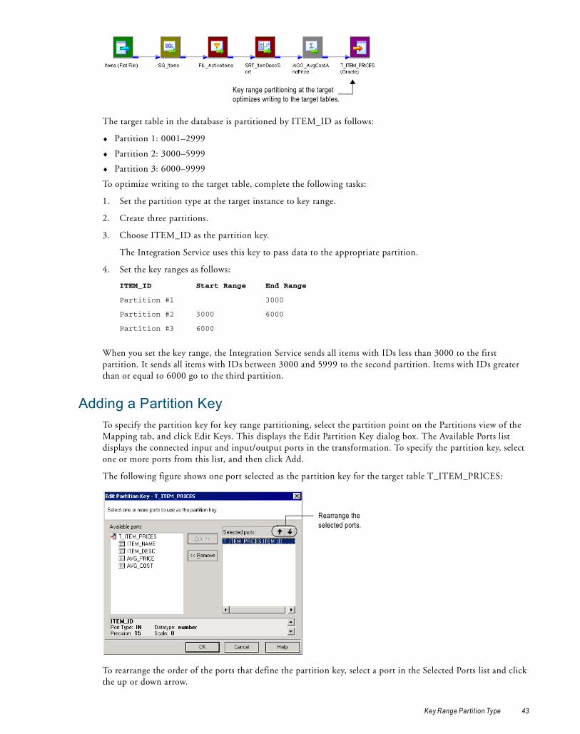
The target table in the database is partitioned by ITEM_ID as follows:
♦ Partition 1: 0001–2999
♦ Partition 2: 3000–5999
♦ Partition 3: 6000–9999
To optimize writing to the target table, complete the following tasks:
1. Set the partition type at the target instance to key range.
2. Create three partitions.
3. Choose ITEM_ID as the partition key.
The Integration Service uses this key to pass data to the appropriate partition.
4. Set the key ranges as follows:
When you set the key range, the Integration Service sends all items with IDs less than 3000 to the first partition. It sends all items with IDs between 3000 and 5999 to the second partition. Items with IDs greater than or equal to 6000 go to the third partition.
Adding a Partition KeyTo specify the partition key for key range partitioning, select the partition point on the Partitions view of the Mapping tab, and click Edit Keys. This displays the Edit Partition Key dialog box. The Available Ports list displays the connected input and input/output ports in the transformation. To specify the partition key, select one or more ports from this list, and then click Add.
The following figure shows one port selected as the partition key for the target table T_ITEM_PRICES:
To rearrange the order of the ports that define the partition key, select a port in the Selected Ports list and click the up or down arrow.
ITEM_ID Start Range End Range
Partition #1 3000
Partition #2 3000 6000
Partition #3 6000
Key range partitioning at the target optimizes writing to the target tables.
Rearrange the selected ports.
Key Range Partition Type 43

In key range partitioning, the order of the ports does not affect how the Integration Service redistributes rows among partitions, but it can affect session performance. For example, you might configure the following compound partition key:
Since boolean comparisons are usually faster than string comparisons, the session may run faster if you arrange the ports in the following order:
Adding Key RangesAfter you identify the ports that make up the partition key, you must enter the ranges for each port on the Partitions view of the Mapping tab.
You can leave the start or end range blank for a partition. When you leave the start range blank, the Integration Service uses the minimum data value as the start range. When you leave the end range blank, the Integration Service uses the maximum data value as the end range.
For example, you can add the following ranges for a key based on CUSTOMER_ID in a pipeline that contains two partitions:
When the Integration Service reads the Customers table, it sends all rows that contain customer IDs less than 135000 to the first partition and all rows that contain customer IDs equal to or greater than 135000 to the second partition. The Integration Service eliminates rows that contain null values or values that fall outside the key ranges.
When you configure a pipeline to load data to a relational target, if a row contains null values in any column that defines the partition key or if a row contains a value that fall outside all of the key ranges, the Integration Service sends that row to the first partition.
When you configure a pipeline to read data from a relational source, the Integration Service reads rows that fall within the key ranges. It does not read rows with null values in any partition key column.
If you want to read rows with null values in the partition key, use pass-through partitioning and create an SQL override.
Adding Filter ConditionsIf you specify key range partitioning for a relational source, you can specify optional filter conditions or override the SQL query.
Rules and Guidelines for Creating Key RangesUse the following rules and guidelines when you create key ranges:
♦ The partition key must contain at least one port.
♦ If you choose key range partitioning at any partition point, you must specify a range for each port in the partition key.
♦ Use the standard PowerCenter date format to enter dates in key ranges.
Selected Ports
ITEMS.DESCRIPTION
ITEMS.DISCONTINUED_FLAG
Selected Ports
ITEMS.DISCONTINUED_FLAG
ITEMS.DESCRIPTION
CUSTOMER_ID Start Range End Range
Partition #1 135000
Partition #2 135000
44 Chapter 3: Partition Types

♦ The Workflow Manager does not validate overlapping string or numeric ranges.
♦ The Workflow Manager does not validate gaps or missing ranges.
♦ If you choose key range partitioning and need to enter a date range for any port, use the standard PowerCenter date format.
♦ When you define key range partitioning at a Source Qualifier transformation, the Integration Service defaults to pass-through partitioning if you change the SQL statement in the Source Qualifier transformation.
♦ The Workflow Manager does not validate overlapping string ranges, overlapping numeric ranges, gaps, or missing ranges.
♦ If a row contains a null value in any column that defines the partition key, or if a row contains values that fall outside all of the key ranges, the Integration Service sends that row to the first partition.
Pass-Through Partition TypeIn pass-through partitioning, the Integration Service processes data without redistributing rows among partitions. Therefore, all rows in a single partition stay in that partition after crossing a pass-through partition point.
When you add a partition point to a pipeline, the master thread creates an additional pipeline stage. Use pass-through partitioning when you want to increase data throughput, but you do not want to increase the number of partitions.
You can specify pass-through partitioning at any valid partition point in a pipeline.
The following figure shows a mapping where pass-through partitioning can increase data throughput:
By default, this mapping contains partition points at the source qualifier and target instance. Since this mapping contains an XML target, you can configure only one partition at any partition point.
In this case, the master thread creates one reader thread to read data from the source, one transformation thread to process the data, and one writer thread to write data to the target. Each pipeline stage processes the rows as follows:
Because the pipeline contains three stages, the Integration Service can process three sets of rows concurrently.
If the Expression transformations are very complicated, processing the second (transformation) stage can take a long time and cause low data throughput. To improve performance, set a partition point at Expression transformation EXP_2 and set the partition type to pass-through. This creates an additional pipeline stage. The master thread creates an additional transformation thread:
Reader Thread Transformation Thread Writer Thread(Third Stage)(Second Stage)(First Stage)
Row Set 1Row Set 2Row Set 3Row Set 4...Row Set n
–Row Set 1Row Set 2Row Set 3...Row Set n-1
––Row Set 1Row Set 2...Row Set n-2
Source Qualifier(First Stage)
Transformations(Second Stage)
Target Instance(Third Stage)
Time
Pass-Through Partition Type 45
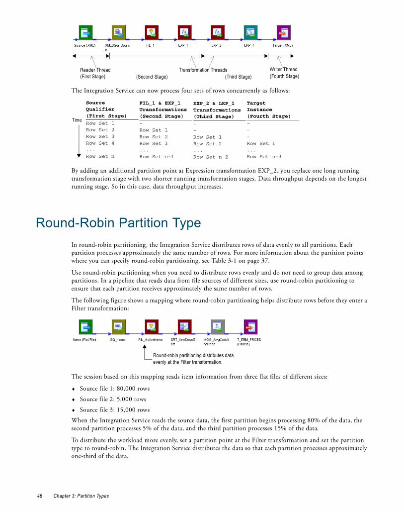
The Integration Service can now process four sets of rows concurrently as follows:
By adding an additional partition point at Expression transformation EXP_2, you replace one long running transformation stage with two shorter running transformation stages. Data throughput depends on the longest running stage. So in this case, data throughput increases.
Round-Robin Partition TypeIn round-robin partitioning, the Integration Service distributes rows of data evenly to all partitions. Each partition processes approximately the same number of rows. For more information about the partition points where you can specify round-robin partitioning, see Table 3-1 on page 37.
Use round-robin partitioning when you need to distribute rows evenly and do not need to group data among partitions. In a pipeline that reads data from file sources of different sizes, use round-robin partitioning to ensure that each partition receives approximately the same number of rows.
The following figure shows a mapping where round-robin partitioning helps distribute rows before they enter a Filter transformation:
The session based on this mapping reads item information from three flat files of different sizes:
♦ Source file 1: 80,000 rows
♦ Source file 2: 5,000 rows
♦ Source file 3: 15,000 rows
When the Integration Service reads the source data, the first partition begins processing 80% of the data, the second partition processes 5% of the data, and the third partition processes 15% of the data.
To distribute the workload more evenly, set a partition point at the Filter transformation and set the partition type to round-robin. The Integration Service distributes the data so that each partition processes approximately one-third of the data.
Reader Thread Transformation Threads Writer Thread(Fourth Stage)(Third Stage)(Second Stage)(First Stage)
Row Set 1Row Set 2Row Set 3Row Set 4...Row Set n
-Row Set 1Row Set 2Row Set 3...Row Set n-1
--Row Set 1Row Set 2...Row Set n-2
Source Qualifier(First Stage)
FIL_1 & EXP_1 Transformations(Second Stage)
EXP_2 & LKP_1 Transformations(Third Stage)
Time---Row Set 1...Row Set n-3
Target Instance(Fourth Stage)
Round-robin partitioning distributes data evenly at the Filter transformation.
46 Chapter 3: Partition Types

C H A P T E R 4
Pushdown Optimization
This chapter includes the following topics:
♦ Overview, 47
♦ Pushdown Optimization Types, 48
♦ Active and Idle Databases, 49
♦ Working with Databases, 50
♦ Pushdown Compatibility, 52
♦ Working with Dates, 54
♦ Working with Expressions, 55
♦ Error Handling, Logging, and Recovery, 60
♦ Working with Slowly Changing Dimensions, 61
♦ Working with Sequences and Views, 61
♦ Using the $$PushdownConfig Mapping Parameter, 65
♦ Configuring Sessions for Pushdown Optimization, 66
OverviewYou can push transformation logic to the source or target database using pushdown optimization. When you run a session configured for pushdown optimization, the Integration Service translates the transformation logic into SQL queries and sends the SQL queries to the database. The source or target database executes the SQL queries to process the transformations.
The amount of transformation logic you can push to the database depends on the database, transformation logic, and mapping and session configuration. The Integration Service processes all transformation logic that it cannot push to a database.
Use the Pushdown Optimization Viewer to preview the SQL statements and mapping logic that the Integration Service can push to the source or target database. You can also use the Pushdown Optimization Viewer to view the messages related to pushdown optimization.
The following figure shows a mapping containing transformation logic that can be pushed to the source database:
47

This mapping contains an Expression transformation that creates an item ID based on the store number 5419 and the item ID from the source. To push the transformation logic to the database, the Integration Service generates the following SQL statement:
INSERT INTO T_ITEMS(ITEM_ID, ITEM_NAME, ITEM_DESC) SELECT CAST((CASE WHEN 5419 IS NULL THEN '' ELSE 5419 END) + '_' + (CASE WHEN ITEMS.ITEM_ID IS NULL THEN '' ELSE ITEMS.ITEM_ID END) AS INTEGER), ITEMS.ITEM_NAME, ITEMS.ITEM_DESC FROM ITEMS2 ITEMS
The Integration Service generates an INSERT SELECT statement to retrieve the ID, name, and description values from the source table, create new item IDs, and insert the values into the ITEM_ID, ITEM_NAME, and ITEM_DESC columns in the target table. It concatenates the store number 5419, an underscore, and the original ITEM ID to get the new item ID.
Pushdown Optimization TypesYou can configure the following types of pushdown optimization:
♦ Source-side pushdown optimization. The Integration Service pushes as much transformation logic as possible to the source database.
♦ Target-side pushdown optimization. The Integration Service pushes as much transformation logic as possible to the target database.
♦ Full pushdown optimization. The Integration Service attempts to push all transformation logic to the target database. If the Integration Service cannot push all transformation logic to the database, it performs both source-side and target-side pushdown optimization.
Running Source-Side Pushdown Optimization SessionsWhen you run a session configured for source-side pushdown optimization, the Integration Service analyzes the mapping from the source to the target or until it reaches a downstream transformation it cannot push to the source database.
The Integration Service generates and executes a SELECT statement based on the transformation logic for each transformation it can push to the database. Then, it reads the results of this SQL query and processes the remaining transformations.
Running Target-Side Pushdown Optimization SessionsWhen you run a session configured for target-side pushdown optimization, the Integration Service analyzes the mapping from the target to the source or until it reaches an upstream transformation it cannot push to the target database. It generates an INSERT, DELETE, or UPDATE statement based on the transformation logic for each transformation it can push to the target database. The Integration Service processes the transformation logic up to the point that it can push the transformation logic to the database. Then, it executes the generated SQL on the target database.
Running Full Pushdown Optimization Sessions To use full pushdown optimization, the source and target databases must be in the same relational database management system. When you run a session configured for full pushdown optimization, the Integration Service analyzes the mapping from the source to the target or until it reaches a downstream transformation it
48 Chapter 4: Pushdown Optimization
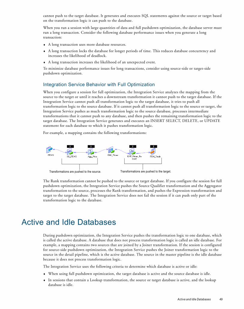
cannot push to the target database. It generates and executes SQL statements against the source or target based on the transformation logic it can push to the database.
When you run a session with large quantities of data and full pushdown optimization, the database server must run a long transaction. Consider the following database performance issues when you generate a long transaction:
♦ A long transaction uses more database resources.
♦ A long transaction locks the database for longer periods of time. This reduces database concurrency and increases the likelihood of deadlock.
♦ A long transaction increases the likelihood of an unexpected event.
To minimize database performance issues for long transactions, consider using source-side or target-side pushdown optimization.
Integration Service Behavior with Full OptimizationWhen you configure a session for full optimization, the Integration Service analyzes the mapping from the source to the target or until it reaches a downstream transformation it cannot push to the target database. If the Integration Service cannot push all transformation logic to the target database, it tries to push all transformation logic to the source database. If it cannot push all transformation logic to the source or target, the Integration Service pushes as much transformation logic to the source database, processes intermediate transformations that it cannot push to any database, and then pushes the remaining transformation logic to the target database. The Integration Service generates and executes an INSERT SELECT, DELETE, or UPDATE statement for each database to which it pushes transformation logic.
For example, a mapping contains the following transformations:
The Rank transformation cannot be pushed to the source or target database. If you configure the session for full pushdown optimization, the Integration Service pushes the Source Qualifier transformation and the Aggregator transformation to the source, processes the Rank transformation, and pushes the Expression transformation and target to the target database. The Integration Service does not fail the session if it can push only part of the transformation logic to the database.
Active and Idle DatabasesDuring pushdown optimization, the Integration Service pushes the transformation logic to one database, which is called the active database. A database that does not process transformation logic is called an idle database. For example, a mapping contains two sources that are joined by a Joiner transformation. If the session is configured for source-side pushdown optimization, the Integration Service pushes the Joiner transformation logic to the source in the detail pipeline, which is the active database. The source in the master pipeline is the idle database because it does not process transformation logic.
The Integration Service uses the following criteria to determine which database is active or idle:
♦ When using full pushdown optimization, the target database is active and the source database is idle.
♦ In sessions that contain a Lookup transformation, the source or target database is active, and the lookup database is idle.
Transformations are pushed to the target.Transformations are pushed to the source.
Active and Idle Databases 49

♦ In sessions that contain a Joiner transformation, the source in the detail pipeline is active, and the source in the master pipeline is idle.
♦ In sessions that contain a Union transformation, the source in the first input group is active. The sources in other input groups are idle.
To push transformation logic to an active database, the database user account of the active database must be able to read from the idle databases.
Working with DatabasesYou can configure pushdown optimization for the following databases:
♦ IBM DB2
♦ Microsoft SQL Server
♦ Netezza
♦ Oracle
♦ Sybase ASE
♦ Teradata
♦ Databases that use ODBC drivers
When you push transformation logic to a database, the database may produce different output than the Integration Service. In addition, the Integration Service can usually push more transformation logic to a database if you use a native driver, instead of an ODBC driver.
Comparing the Output of the Integration Service and DatabasesThe Integration Service and databases can produce different results when processing the same transformation logic. The Integration Service sometimes converts data to a different format when it reads data. The Integration Service and database may also handle null values, case sensitivity, and sort order differently.
The database and Integration Service produce different output when the following settings and conversions are different:
♦ Nulls treated as the highest or lowest value. The Integration Service and a database can treat null values differently. For example, you want to push a Sorter transformation to an Oracle database. In the session, you configure nulls as the lowest value in the sort order. Oracle treats null values as the highest value in the sort order.
♦ Sort order. The Integration Service and a database can use different sort orders. For example, you want to push the transformations in a session to a Microsoft SQL Server database, which is configured to use a sort order that is not case sensitive. You configure the session properties to use the binary sort order, which is case sensitive. The results differ based on whether the Integration Service or Microsoft SQL Server database process the transformation logic.
♦ Case sensitivity. The Integration Service and a database can treat case sensitivity differently. For example, the Integration Service uses case sensitive queries and the database does not. A Filter transformation uses the following filter condition: IIF(col_varchar2 = ‘CA’, TRUE, FALSE). You need the database to return rows that match ‘CA.’ However, if you push this transformation logic to a Microsoft SQL Server database that is not case sensitive, it returns rows that match the values ‘Ca,’ ‘ca,’ ‘cA,’ and ‘CA.’
♦ Numeric values converted to character values. The Integration Service and a database can convert the same numeric value to a character value in different formats. The database can convert numeric values to an unacceptable character format. For example, a table contains the number 1234567890. When the Integration Service converts the number to a character value, it inserts the characters ‘1234567890.’ However, a database might convert the number to ‘1.2E9.’ The two sets of characters represent the same
50 Chapter 4: Pushdown Optimization

value. However, if you require the characters in the format ‘1234567890,’ you can disable pushdown optimization.
♦ Precision. The Integration Service and a database can have different precision for particular datatypes. Transformation datatypes use a default numeric precision that can vary from the native datatypes. For example, a transformation Decimal datatype has a precision of 1-28. The corresponding Teradata Decimal datatype has a precision of 1-18. The results can vary if the database uses a different precision than the Integration Service.
Using ODBC DriversWhen you use a native driver for a database, the Integration Service generates SQL statements using native database SQL. When you use ODBC drivers, the Integration Service usually cannot detect the database type. As a result, it generates SQL statements using ANSI SQL. The Integration Service can generate more functions when it generates SQL statements using the native language than ANSI SQL.
Note: You must use an ODBC driver for a Netezza database. Although the Integration Service uses an ODBC driver for Netezza, the Integration Service detects that the database is Netezza and generates native database SQL when pushing the transformation logic to the Netezza database.
In some cases, ANSI SQL is not compatible with the database syntax. The following sections describe problems that you can encounter when you use ODBC drivers. When possible, use native drivers to prevent these problems.
IBM DB2You can encounter the following problems using ODBC drivers with an IBM DB2 database:
♦ A session containing a Sorter transformation fails if the sort is distinct and not case sensitive, and one of the sort keys is a string datatype.
♦ A session containing a Lookup transformation fails for source-side or full pushdown optimization.
♦ A session that requires type casting fails if the casting is from float or double to string, or if it requires any other type of casting that IBM DB2 databases disallow.
Microsoft SQL ServerYou can encounter the following problems using ODBC drivers with a Microsoft SQL Server database:
♦ A session containing a Sorter transformation fails if the sort is distinct and not case sensitive.
♦ A pushdown optimization session fails when it loads datetime data to a Microsoft SQL Server target using an ODBC driver. The Integration Service converts datetime data to the ODBC Timestamp datatype, which is not a supported Microsoft SQL Server datatype.
Sybase ASEYou can encounter the following problems using ODBC drivers with a Sybase ASE database:
♦ The session fails when it performs datatype conversions and you use Sybase ASE 12.5 or below.
♦ The session fails if you use a Joiner transformation configured for a full outer join.
TeradataYou can encounter the following problems using ODBC drivers with a Teradata database:
♦ The session fails if it converts a numeric datatype with precision greater than 18.
♦ The session fails when you use full pushdown optimization for a session containing a Sorter transformation.
♦ A sort on a distinct key can give inconsistent results if the sort is not case sensitive and one port is a character port.
Working with Databases 51

♦ An Integration Service and a database can produce different results for a session that contains an Aggregator transformation if the group by port is of a string datatype and is not case sensitive.
♦ A session that contains a Lookup transformation fails if it is configured for target-side pushdown optimization.
♦ A session that contains a date-to-string datatype conversion fails.
♦ The Integration Service cannot detect unsupported date formats when pushing string-to-date or date-to-string conversions to Netezza.
Rules and Guidelines for NetezzaUse the following rules and guidelines for pushdown optimization to a Netezza database:
♦ You must enable the Pre 85 Timestamp Compatibility session property to perform target-side pushdown optimization on Netezza if the Netezza database table contains a date, time, or timestamp column. If you disable the option, the Integration Service processes the target operation.
♦ If you configure the Lookup transformation to report an error on multiple matches and the Integration Service pushes the lookup to a Netezza database, Netezza does not return an error on multiple matches. Netezza returns multiple rows for each match.
Pushdown CompatibilityTo push a transformation with multiple connections to a database, the connections must be pushdown compatible. Connections are pushdown compatible if they connect to databases on the same database management system and the Integration Service can identify the database tables that the connections access.
The following transformations can have multiple connections:
♦ Joiner. The Joiner transformation can join data from multiple source connections.
♦ Union. The Union transformation can merge data from multiple source connections.
♦ Lookup. The connection for the Lookup transformation can differ from the source connection.
♦ Target. The target connection can differ from the source connection.
Each connection object is pushdown compatible with itself. If you configure a session to use the same connection object for the source and target connections, the Integration Service can push the transformation logic to the source or target database.
Some relational connections are pushdown compatible if they are of the same database type, have the same database user name and password, and have certain identical properties.
Table 4-1 lists the connection properties that must be identical for each database type:
Table 4-1. Connection Properties that Must be Identical for Pushdown Compatible Connections
Database Type Connection Properties that Must be Identical
IBM DB2 Connect stringCode pageConnection environment SQLTransaction environment SQL
Microsoft SQL Server Code pageServer nameDomain nameUse trusted connectionConnection environment SQLTransaction environment SQL
52 Chapter 4: Pushdown Optimization

Note: The Integration Service performs a case-sensitive string comparison to verify that connection properties are identical.
Netezza databases in the same relational database management system are pushdown incompatible. A Netezza database is only pushdown compatible with itself.
If the connection properties in Table 4-1 for connections of the same database type are identical, but the database user names and passwords differ, you might still be able to make the connections pushdown compatible.
Incompatible Users for Database ConnectionsIf the database user names and passwords of otherwise compatible connections do not match, you must provide additional information to make the connections compatible.
To make the connections pushdown compatible, perform the following actions:
1. Verify that the database user of the active database has read permission on all idle databases.
2. Enable the Allow Pushdown for User Incompatible Connections session property.
3. For each idle connection to Microsoft SQL Server and Sybase, you must also specify the database name in the connection property and table owners for all lookups and sources.
Qualifying Names of Tables in Idle DatabasesWhen the Integration Service generates SQL to push transformations to an active database, the generated SQL references at least one table in the idle database.
To ensure that the Integration Service can identify all tables, you must qualify the names of tables in idle databases for the following cases:
♦ The active and idle connections have the same connection properties and are of the same database type, however the database user names and passwords are different.
♦ The Source Qualifier transformation contains a source filter or user-defined join.
Note: The Integration Service qualifies the names of tables in idle databases for all other cases.
Qualify the name of a source table in the Owner Name session property for the Source Qualifier transformation. Qualify the name of a lookup table in the Lookup Table Name session property for the Lookup transformation.
Oracle Connect stringCode pageConnection environment SQLTransaction environment SQL
Sybase ASE Code pageServer nameConnection environment SQLTransaction environment SQL
Teradata Code pageData source nameConnection environment SQLTransaction environment SQL
Table 4-1. Connection Properties that Must be Identical for Pushdown Compatible Connections
Database Type Connection Properties that Must be Identical
Pushdown Compatibility 53

Use the following syntax to qualify a table name:
Working with DatesThe Integration Service and database can process dates differently. When you configure the session to push date conversion to the database, you can receive unexpected results or the session can fail.
The database can produce different output than the Integration Service when the following date settings and conversions are different:
♦ Date values converted to character values. The Integration Service converts the transformation Date/Time datatype to the native datatype that supports subsecond precision in the database. The session fails if you configure the datetime format in the session to a format that the database does not support. For example, when the Integration Service performs the ROUND function on a date, it stores the date value in a character column, using the format MM/DD/YYYY HH:MI:SS.US. When the database performs this function, it stores the date in the default date format for the database. If the database is Oracle, it stores the date as the default DD-MON-YY. If you require the date to be in the format MM/DD/YYYY HH:MI:SS.US, you can disable pushdown optimization.
♦ Date formats for TO_CHAR and TO_DATE functions. The Integration Service uses the date format in the TO_CHAR or TO_DATE function when the Integration Service pushes the function to the database. The database converts each date string to a datetime value supported by the database.
For example, the Integration Service pushes the following expression to the database:
TO_DATE( DATE_PROMISED, 'MM/DD/YY' )
The database interprets the date string in the DATE_PROMISED port based on the specified date format string MM/DD/YY. The database converts each date string, such as 01/22/98, to the supported date value, such as Jan 22 1998 00:00:00.
If the Integration Service pushes a date format to an IBM DB2, a Microsoft SQL Server, or a Sybase database that the database does not support, the Integration Service stops pushdown optimization and processes the transformation.
The Integration Service converts all dates before pushing transformations to an Oracle or Teradata database. If the database does not support the date format after the date conversion, the session fails.
♦ HH24 date format. You cannot use the HH24 format in the date format string for Teradata. When the Integration Service generates SQL for a Teradata database, it uses the HH format string instead.
♦ Blank spaces in date format strings. You cannot use blank spaces in the date format string in Teradata. When the Integration Service generates SQL for a Teradata database, it substitutes the space with ‘B.’
♦ Handling subsecond precision for a Lookup transformation. If you enable subsecond precision for a Lookup transformation, the database and Integration Service perform the lookup comparison using the subsecond precision, but return different results. Unlike the Integration Service, the database does not truncate the lookup results based on subsecond precision. For example, you configure the Lookup transformation to show subsecond precision to the millisecond. If the lookup result is 8:20:35.123456, a database returns 8:20:35.123456, but the Integration Service returns 8:20:35.123.
Database Type Syntax
IBM DB2 <table owner>.<table name>
Microsoft SQL Server <database name>.<table owner>.<table name>
Netezza Not supported
Oracle <table owner>.<table name>
Sybase ASE <database name>.<table owner>.<table name>
Teradata <database name>.<table name>
54 Chapter 4: Pushdown Optimization
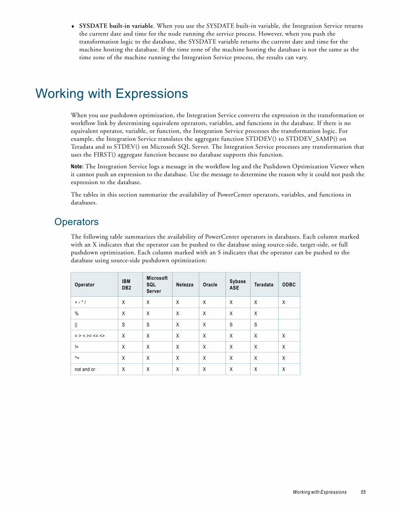
♦ SYSDATE built-in variable. When you use the SYSDATE built-in variable, the Integration Service returns the current date and time for the node running the service process. However, when you push the transformation logic to the database, the SYSDATE variable returns the current date and time for the machine hosting the database. If the time zone of the machine hosting the database is not the same as the time zone of the machine running the Integration Service process, the results can vary.
Working with ExpressionsWhen you use pushdown optimization, the Integration Service converts the expression in the transformation or workflow link by determining equivalent operators, variables, and functions in the database. If there is no equivalent operator, variable, or function, the Integration Service processes the transformation logic. For example, the Integration Service translates the aggregate function STDDEV() to STDDEV_SAMP() on Teradata and to STDEV() on Microsoft SQL Server. The Integration Service processes any transformation that uses the FIRST() aggregate function because no database supports this function.
Note: The Integration Service logs a message in the workflow log and the Pushdown Optimization Viewer when it cannot push an expression to the database. Use the message to determine the reason why it could not push the expression to the database.
The tables in this section summarize the availability of PowerCenter operators, variables, and functions in databases.
OperatorsThe following table summarizes the availability of PowerCenter operators in databases. Each column marked with an X indicates that the operator can be pushed to the database using source-side, target-side, or full pushdown optimization. Each column marked with an S indicates that the operator can be pushed to the database using source-side pushdown optimization:
Operator IBM DB2
Microsoft SQL Server
Netezza Oracle Sybase ASE Teradata ODBC
+ - * / X X X X X X X
% X X X X X X
|| S S X X S S
= > < >= <= <> X X X X X X X
!= X X X X X X X
^= X X X X X X X
not and or X X X X X X X
Working with Expressions 55
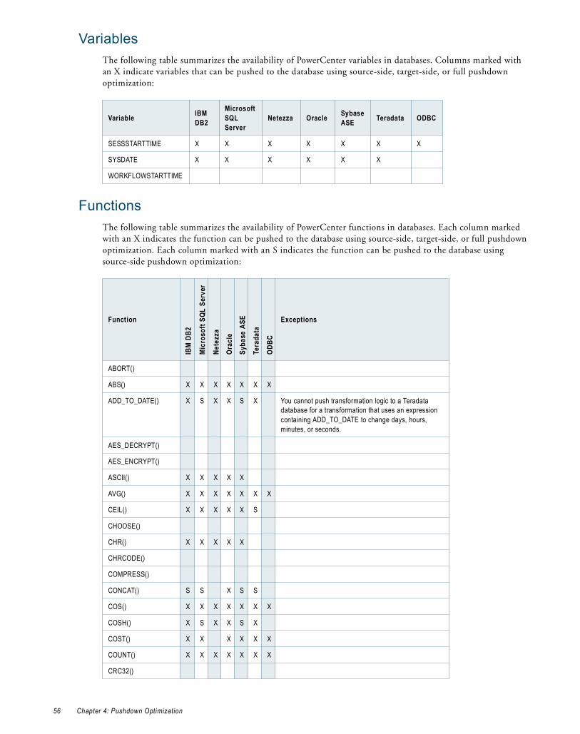
VariablesThe following table summarizes the availability of PowerCenter variables in databases. Columns marked with an X indicate variables that can be pushed to the database using source-side, target-side, or full pushdown optimization:
FunctionsThe following table summarizes the availability of PowerCenter functions in databases. Each column marked with an X indicates the function can be pushed to the database using source-side, target-side, or full pushdown optimization. Each column marked with an S indicates the function can be pushed to the database using source-side pushdown optimization:
Variable IBM DB2
Microsoft SQL Server
Netezza Oracle Sybase ASE Teradata ODBC
SESSSTARTTIME X X X X X X X
SYSDATE X X X X X X
WORKFLOWSTARTTIME
Function
IBM
DB2
Mic
roso
ft SQ
L Se
rver
Nete
zza
Orac
leSy
base
ASE
Tera
data
ODBC
Exceptions
ABORT()
ABS() X X X X X X X
ADD_TO_DATE() X S X X S X You cannot push transformation logic to a Teradata database for a transformation that uses an expression containing ADD_TO_DATE to change days, hours, minutes, or seconds.
AES_DECRYPT()
AES_ENCRYPT()
ASCII() X X X X X
AVG() X X X X X X X
CEIL() X X X X X S
CHOOSE()
CHR() X X X X X
CHRCODE()
COMPRESS()
CONCAT() S S X S S
COS() X X X X X X X
COSH() X S X X S X
COST() X X X X X X
COUNT() X X X X X X X
CRC32()
56 Chapter 4: Pushdown Optimization
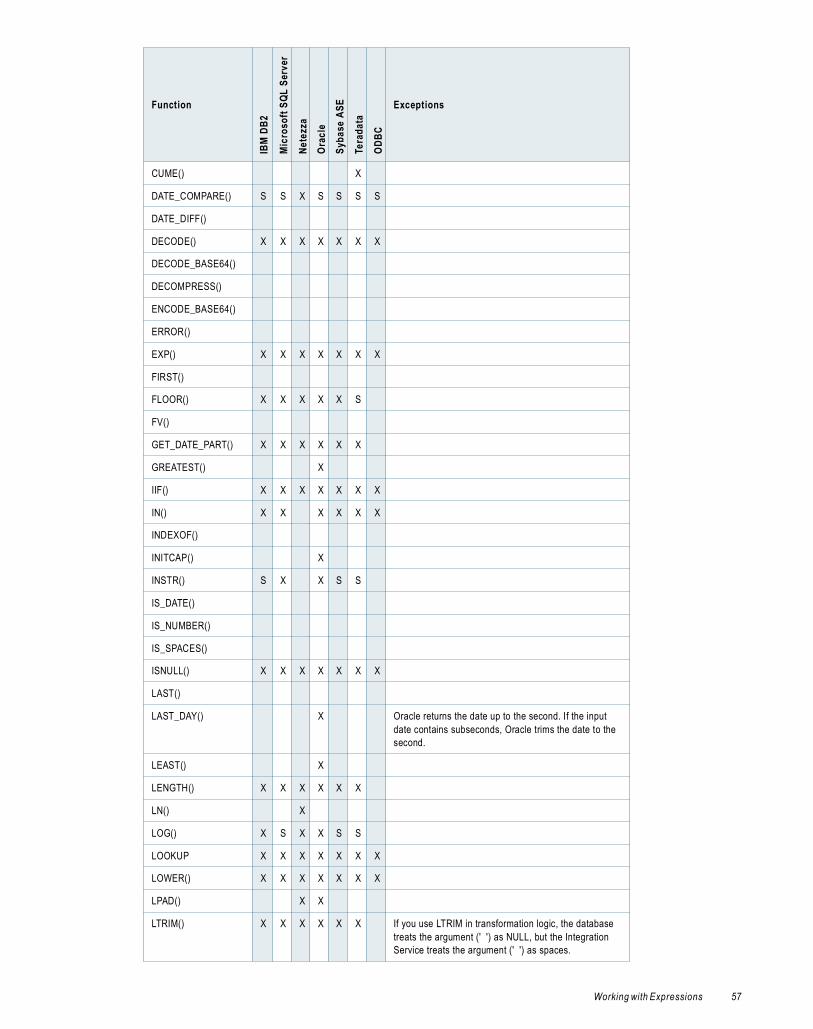
CUME() X
DATE_COMPARE() S S X S S S S
DATE_DIFF()
DECODE() X X X X X X X
DECODE_BASE64()
DECOMPRESS()
ENCODE_BASE64()
ERROR()
EXP() X X X X X X X
FIRST()
FLOOR() X X X X X S
FV()
GET_DATE_PART() X X X X X X
GREATEST() X
IIF() X X X X X X X
IN() X X X X X X
INDEXOF()
INITCAP() X
INSTR() S X X S S
IS_DATE()
IS_NUMBER()
IS_SPACES()
ISNULL() X X X X X X X
LAST()
LAST_DAY() X Oracle returns the date up to the second. If the input date contains subseconds, Oracle trims the date to the second.
LEAST() X
LENGTH() X X X X X X
LN() X
LOG() X S X X S S
LOOKUP X X X X X X X
LOWER() X X X X X X X
LPAD() X X
LTRIM() X X X X X X If you use LTRIM in transformation logic, the database treats the argument (' ') as NULL, but the Integration Service treats the argument (' ') as spaces.
Function
IBM
DB2
Mic
roso
ft SQ
L Se
rver
Nete
zza
Orac
leSy
base
ASE
Tera
data
ODBC
Exceptions
Working with Expressions 57

MAKE_DATE_TIME()
MAX() X X X X X X X
MD5()
MEDIAN()
METAPHONE()
MIN() X X X X X X X
MOD() X X X X X X
MOVINGAVG()
MOVINGSUM()
NPER()
PERCENTILE()
PMT()
POWER() X X X X X X X
PV()
RAND()
RATE()
REG_EXTRACT()
REG_MATCH()
REG_REPLACE
REPLACECHR()
REPLACESTR()
REVERSE()
ROUND(DATE) X
ROUND(NUMBER) X X X X X S
RPAD() X X
RTRIM() X X X X X X If you use RTRIM in transformation logic, the database treats the argument (' ') as NULL, but the Integration Service treats the argument (' ') as spaces.
SET_DATE_PART()
SIGN() X X X X X S
SIN() X X X X X X X
SINH() X S X X S X
SOUNDEX() X X X X If you use SOUNDEX in transformation logic, the database treats the argument (' ') as NULL, but the Integration Service treats the argument (' ') as spaces.
SQRT() X X X X X X X
Function
IBM
DB2
Mic
roso
ft SQ
L Se
rver
Nete
zza
Orac
leSy
base
ASE
Tera
data
ODBC
Exceptions
58 Chapter 4: Pushdown Optimization

STDDEV() X X X X An IBM DB2 database and the Integration Service produce different results for STDDEV. IBM DB2 uses a different algorithm than other databases to calculate STDDEV.
SUBSTR() S S X X S S
SUM() X X X X X X X
SYSDATE() X X X X X X X When you push SYSDATE to the database, the database server returns the timestamp in the time zone of the database server, not the Integration Service.
SYSTIMESTAMP() X X X X X X X When you push SYSTIMESTAMP to the database, the database server returns the time stamp in the time zone of the database server, not the Integration Service. If you specify the format for SYSTIMESTAMP and push SYSTIMESTAMP to an IBM DB2 or a Sybase database, the database ignores the format and returns the complete time stamp. You can push SYSTIMESTAMP(‘SS’) to a Netezza database, but not SYSTIMESTAMP(‘MS’) or SYSTIMESTAMP(‘US’).
TAN() X X X X X X X
TANH() X S X X S X
TO_BIGINT X X X X X X X
TO_CHAR(DATE) X X X X X S To push this function to Netezza, dates with subsecond precision must be in the YYYY-MM-DD HH24:MI:SS.US format. If the format is different, the Integration Service does not push the function to Netezza.
TO_CHAR(NUMBER) X X X X X X
TO_DATE() X X X X X X To push this function to Netezza, dates with subsecond precision must be in the YYYY-MM-DD HH24:MI:SS.US format. If the format is different, the Integration Service does not push the function to Netezza.
TO_DECIMAL() X X X X X X X
TO_FLOAT() X X X X X X X
TO_INTEGER() X S X X S X
TRUNC(DATE) X X
TRUNC(NUMBER) X X X X S S
UPPER() X X X X X X X
VARIANCE() X X X X An IBM DB2 database and the Integration Service produce different results for VARIANCE. IBM DB2 uses a different algorithm than other databases to calculate VARIANCE.
Function
IBM
DB2
Mic
roso
ft SQ
L Se
rver
Nete
zza
Orac
leSy
base
ASE
Tera
data
ODBC
Exceptions
Working with Expressions 59
Error Handling, Logging, and RecoveryThe Integration Service and database process error handling, logging, and recovery differently.
Error HandlingWhen the Integration Service pushes transformation logic to the database, it cannot track errors that occur in the database. As a result, it handles errors differently than when it processes the transformations in the session. When the Integration Service runs a session configured for full pushdown optimization and an error occurs, the database handles the errors. When the database handles errors, the Integration Service does not write reject rows to the reject file.
LoggingWhen the Integration Service pushes transformation logic to the database, it cannot trace all the events that occur inside the database server. The statistics the Integration Service can trace depend on the type of pushdown optimization. When you push transformation logic to the database, the Integration Service generates a session log with the following differences:
♦ The session log does not contain details for transformations processed by the database.
♦ The session log does not contain the thread busy percentage when the session is configured for full pushdown optimization.
♦ The session log contains the number of loaded rows when the session is configured for source-side, target-side, and full pushdown optimization.
♦ The session log does not contain the number of rows read from the source when the Integration Service uses full pushdown optimization and pushes all transformation logic to the database.
♦ The session log contains the number of rows read from each source when the Integration Service uses source-side pushdown optimization.
RecoveryIf you configure a session for full pushdown optimization and the session fails, the Integration Service cannot perform incremental recovery because the database processes the transformations. Instead, the database rolls back the transactions. If the database server fails, it rolls back transactions when it restarts. If the Integration Service fails, the database server rolls back the transaction.
If the failure occurs while the Integration Service is creating temporary sequence objects or views in the database, which is before any rows have been processed, the Integration Service runs the generated SQL on the database again.
If the failure occurs before the database processes all rows, the Integration Service performs the following tasks:
1. If applicable, the Integration Service drops and recreates temporary view or sequence objects in the database to ensure duplicate values are not produced.
2. The Integration Service runs the generated SQL on the database again.
If the failure occurs while the Integration Service is dropping the temporary view or sequence objects from the database, which is after all rows are processed, the Integration Service tries to drop the temporary objects again.
RELATED TOPICS:♦ “Working with Sequences and Views” on page 61
60 Chapter 4: Pushdown Optimization

Working with Slowly Changing DimensionsYou can push Type 1 and Type 3 slowly changing dimensions logic to a database. The slowly changing dimensions logic in a mapping can be comprised of multiple transformations. The rules and guidelines of each transformation determine how much slowly changing dimensions logic you can push to a database.
Use the following rules and guidelines when you configure the Integration Service to push slowly changing dimensions transformation logic to a database:
♦ You can push transformations included in Type 1 and Type 3 slowly changing dimensions mapping to an Oracle or IBM DB2 database.
♦ The source data must not have duplicate rows. The database can become deadlocked if it makes multiple updates to the same row.
♦ You must create the slowly changing dimensions mapping using the Slowly Changing Dimensions Wizard version 8.5 or higher. You cannot push the slowly changing dimensions logic to the database if it was created by the Slowly Changing Dimensions Wizard from a previous version.
RELATED TOPICS:♦ “Pushdown Optimization and Transformations” on page 71
Working with Sequences and ViewsTo push transformation logic to a database, the Integration Service might create temporary sequences or views in the database. After the database transaction completes, the Integration Service drops sequence and view objects created for pushdown optimization.
SequencesTo push Sequence Generator transformation logic to a database, you must configure the session for pushdown optimization with sequences.
If you configure a session to push Sequence Generator transformation logic to a database, the Integration Service completes the following tasks:
1. Creates a sequence object in the database. The Integration Service creates the sequence object in the database based on the Sequence Generator transformation logic. The Integration Service creates a unique name for each sequence object. To create a unique sequence object name, it adds the prefix PM_S to a value generated by a hash function.
2. Generates the SQL query and executes it against the database. The Integration Service generates and executes the SQL query to push the Sequence Generator transformation logic to the database.
3. Drops the sequence object from the database. When the transaction completes, the Integration Service drops the sequence object that it created in the database.
RELATED TOPICS:♦ “Configuring Sessions for Pushdown Optimization” on page 66
Sequence Creation ExampleYou create the following mapping that uses a Sequence Generator transformation to generate primary keys for a relational target:
Working with Slowly Changing Dimensions 61

When the Integration Service pushes transformation logic to the database, it executes the following SQL statement to create the sequence object in the source database:
CREATE SEQUENCE PM_S6UHW42OGXTY7NICHYIOSRMC5XQ START WITH 1 INCREMENT BY 1 MINVALUE 0 MAXVALUE 9223372036854775807 NOCYCLE CACHE 9223372036854775807
After the Integration Service creates the sequence object, the Integration Service executes the SQL query to process the transformation logic contained in the mapping:
INSERT INTO STORE_SALES(PRIMARYKEY, QUARTER, SALES, STORE_ID) SELECT CAST(PM_S6UHW42OGXTY7NICHYIOSRMC5XQ.NEXTVAL AS FLOAT), CAST(CAST(SALES_BYSTOREQUARTER_SRC.QUARTER AS FLOAT) AS VARCHAR2(10)), CAST(CAST(SALES_BYSTOREQUARTER_SRC.SALES AS NUMBER(10, 2)) AS NUMBER(25, 2)), CAST(SALES_BYSTOREQUARTER_SRC.STORE_ID AS NUMBER(0, 0)) FROM SALES_BYSTOREQUARTER_SRC
After the session completes, the Integration Service drops the sequence object from the database. If the session fails, the Integration Service drops and recreates the sequence object before performing recovery tasks.
ViewsYou must configure the session for pushdown optimization with views to enable the Integration Service to create the view objects in the database.
The Integration Service creates a view object under the following conditions:
♦ You configure pushdown optimization for a Source Qualifier or Lookup transformation configured with an SQL override.
♦ You configure pushdown optimization for a Lookup transformation configured with a filter.
♦ You configure pushdown optimization for an unconnected Lookup transformation.
Note: The Integration Service does not parse or validate the SQL overrides. If you configure a session to push the Source Qualifier or Lookup transformation with an SQL override to the database, test the SQL override against the database before you run the session.
If you configure the session for pushdown optimization with views, the Integration Service completes the following tasks:
1. Creates a view in the database. The Integration Service creates a view in the database based on the lookup filter, unconnected lookup, or SQL override in the Source Qualifier or Lookup transformation. To create a unique view name, the Integration Service adds the prefix PM_V to a value generated by a hash function.
2. Executes an SQL query against the view. After the Integration Service creates a view object, it executes an SQL query against the view created in the database to push the transformation logic to the source.
3. Drops the view from the database. When the transaction completes, the Integration Service drops the view it created.
RELATED TOPICS:♦ “Configuring Sessions for Pushdown Optimization” on page 66
View Creation ExampleYou create the following mapping that searches for 94117 zip codes in a customer database:
62 Chapter 4: Pushdown Optimization

You want the search to return customers whose names match variations of the name Johnson, including names such as Johnsen, Jonssen, and Jonson. To perform the name matching, you enter the following SQL override for the Source Qualifier transformation:
SELECT CUSTOMERS.CUSTOMER_ID, CUSTOMERS.COMPANY, CUSTOMERS.FIRST_NAME, CUSTOMERS.LAST_NAME, CUSTOMERS.ADDRESS1, CUSTOMERS.ADDRESS2, CUSTOMERS.CITY, CUSTOMERS.STATE, CUSTOMERS.POSTAL_CODE, CUSTOMERS.PHONE, CUSTOMERS.EMAIL FROM CUSTOMERS WHERE CUSTOMERS.LAST_NAME LIKE 'John%' OR CUSTOMERS.LAST_NAME LIKE 'Jon%'
When the Integration Service pushes transformation logic for this session to the database, it executes the following SQL statement to create a view in the source database:
CREATE VIEW PM_V4RZRW5GWCKUEWH35RKDMDPRNXI (CUSTOMER_ID, COMPANY, FIRST_NAME, LAST_NAME, ADDRESS1, ADDRESS2, CITY, STATE, POSTAL_CODE, PHONE, EMAIL) AS SELECT CUSTOMERS.CUSTOMER_ID, CUSTOMERS.COMPANY, CUSTOMERS.FIRST_NAME, CUSTOMERS.LAST_NAME, CUSTOMERS.ADDRESS1, CUSTOMERS.ADDRESS2, CUSTOMERS.CITY, CUSTOMERS.STATE, CUSTOMERS.POSTAL_CODE, CUSTOMERS.PHONE, CUSTOMERS.EMAIL FROM CUSTOMERS WHERE CUSTOMERS.LAST_NAME LIKE 'John%' OR CUSTOMERS.LAST_NAME LIKE 'Jon%'
After the Integration Service creates the view, it executes an SQL query to perform the transformation logic in the mapping:
SELECT PM_V4RZRW5GWCKUEWH35RKDMDPRNXI.CUSTOMER_ID, PM_V4RZRW5GWCKUEWH35RKDMDPRNXI.COMPANY, PM_V4RZRW5GWCKUEWH35RKDMDPRNXI.FIRST_NAME, PM_V4RZRW5GWCKUEWH35RKDMDPRNXI.LAST_NAME, PM_V4RZRW5GWCKUEWH35RKDMDPRNXI.ADDRESS1, PM_V4RZRW5GWCKUEWH35RKDMDPRNXI.ADDRESS2, PM_V4RZRW5GWCKUEWH35RKDMDPRNXI.CITY, PM_V4RZRW5GWCKUEWH35RKDMDPRNXI.STATE, PM_V4RZRW5GWCKUEWH35RKDMDPRNXI.POSTAL_CODE, PM_V4RZRW5GWCKUEWH35RKDMDPRNXI.PHONE, PM_V4RZRW5GWCKUEWH35RKDMDPRNXI.EMAIL FROM PM_V4RZRW5GWCKUEWH35RKDMDPRNXI WHERE (PM_V4RZRW5GWCKUEWH35RKDMDPRNXI.POSTAL_CODE = 94117)
After the session completes, the Integration Service drops the view from the database. If the session fails, the Integration Service drops and recreates the view before performing recovery tasks.
Troubleshooting Orphaned Sequences and ViewsThe Integration Service might not drop a sequence or view object from a database if the Integration Service, session, or connectivity fails. In this case, manually remove these objects from the database.
Note: Orphaned sequence and view objects in the database do not affect performance.
Complete the following tasks to remove an orphaned sequence or view object from a database:
1. Identify the orphaned objects in the database. You can identify orphaned objects based on the session logs or a query on the database. Analyze the session log to determine orphaned objects from a session run. Run the database query to determine all orphaned objects in the database at a given time.
2. Remove the orphaned objects from the database. You can execute SQL statements to drop the orphaned objects you identified.
Identifying Orphaned Objects Using Session LogsThe Integration Service writes an event log when it creates and drops a view or sequence object. If an Integration Service, session, or connection fails when a session is running, you can check the session log to determine sequence or view objects that were not dropped during the session.
For example, if the Integration Service drops the view PM_V4RZRW, the session log displays the following message:
Working with Sequences and Views 63

MAPPING> TM_6356 Starting pushdown cleanup SQL for source [CUSTOMERS]. : (Tue Feb 14 13:23:46 2006)
MAPPING> TM_6358 Executing pushdown cleanup SQL for source: DROP VIEW PM_V4RZRW
MAPPING> TM_6360 Completed pushdown cleanup SQL for source [CUSTOMERS] successfully. : (Tue Feb 14 13:23:46 2006)
Identifying Orphaned Objects Using an SQL QueryIf the Integration Service does not drop the sequence or view objects, you can execute an SQL query on the database to identify all orphaned sequence or view objects created by the Integration Service. If the Integration Service ran multiple sessions or multiple Integration Services write to the same database account, the SQL query returns all orphaned objects from every session that ran and did not drop sequence or view objects.
When the Integration Service creates a sequence or view object in the database, it adds the prefix PM_S to the names of sequence objects and PM_V to the names of view objects. You can search for these objects based on the prefix to identify them.
The following queries show the syntax to search for sequence objects created by the Integration Service:
IBM DB2:
SELECT SEQNAME FROM SYSCAT.SEQUENCES WHERE SEQSCHEMA = CURRENT SCHEMA AND SEQNAME LIKE ‘PM\_S%’ ESCAPE ‘\’
Oracle:
SELECT SEQUENCE_NAME FROM USER_SEQUENCES WHERE SEQUENCE_NAME LIKE ‘PM\_S%’ ESCAPE ‘\’
The following queries show the syntax to search for view objects created by the Integration Service:
IBM DB2:
SELECT VIEWNAME FROM SYSCAT.VIEWS WHERE VIEWSCHEMA = CURRENT SCHEMA AND VIEW_NAME LIKE ‘PM\_V%’ ESCAPE ‘\’
Oracle:
SELECT VIEW_NAME FROM USER_VIEWS WHERE VIEW_NAME LIKE ‘PM\_V%’ ESCAPE ‘\’
Microsoft SQL Server or Sybase ASE:
SELECT NAME FROM SYSOBJECTS WHERE TYPE=‘V’ AND NAME LIKE ‘PM\_V%’ ESCAPE ‘\’
Teradata:
SELECT TableName FROM DBC.Tables WHERE CreatorName = USER AND TableKind =‘V’AND TableName LIKE ‘PM\_V%’ ESCAPE ‘\’
Removing the Orphaned ObjectsAfter you get a list of the sequence and view objects created by the Integration Service, execute an SQL DROP statement to drop the sequence or view objects from the database.
The following query shows the syntax to drop sequence objects created by the Integration Service on any database:
DROP SEQUENCE <sequence name>
The following query shows the syntax to drop view objects created by the Integration Service on any database:
DROP VIEW <view name>
64 Chapter 4: Pushdown Optimization
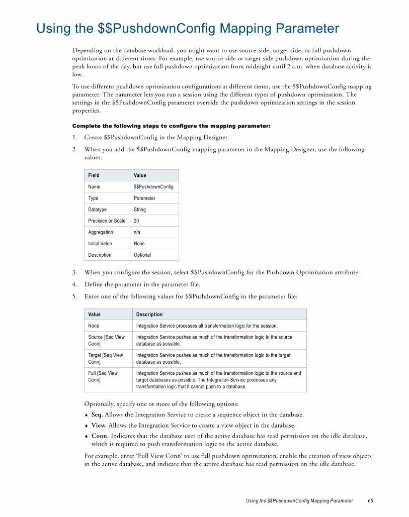
Using the $$PushdownConfig Mapping ParameterDepending on the database workload, you might want to use source-side, target-side, or full pushdown optimization at different times. For example, use source-side or target-side pushdown optimization during the peak hours of the day, but use full pushdown optimization from midnight until 2 a.m. when database activity is low.
To use different pushdown optimization configurations at different times, use the $$PushdownConfig mapping parameter. The parameter lets you run a session using the different types of pushdown optimization. The settings in the $$PushdownConfig parameter override the pushdown optimization settings in the session properties.
Complete the following steps to configure the mapping parameter:
1. Create $$PushdownConfig in the Mapping Designer.
2. When you add the $$PushdownConfig mapping parameter in the Mapping Designer, use the following values:
3. When you configure the session, select $$PushdownConfig for the Pushdown Optimization attribute.
4. Define the parameter in the parameter file.
5. Enter one of the following values for $$PushdownConfig in the parameter file:
Optionally, specify one or more of the following options:
♦ Seq. Allows the Integration Service to create a sequence object in the database.
♦ View. Allows the Integration Service to create a view object in the database.
♦ Conn. Indicates that the database user of the active database has read permission on the idle database, which is required to push transformation logic to the active database.
For example, enter ‘Full View Conn’ to use full pushdown optimization, enable the creation of view objects in the active database, and indicate that the active database has read permission on the idle database.
Field Value
Name $$PushdownConfig
Type Parameter
Datatype String
Precision or Scale 20
Aggregation n/a
Initial Value None
Description Optional
Value Description
None Integration Service processes all transformation logic for the session.
Source [Seq View Conn]
Integration Service pushes as much of the transformation logic to the source database as possible.
Target [Seq View Conn]
Integration Service pushes as much of the transformation logic to the target database as possible.
Full [Seq View Conn]
Integration Service pushes as much of the transformation logic to the source and target databases as possible. The Integration Service processes any transformation logic that it cannot push to a database.
Using the $$PushdownConfig Mapping Parameter 65
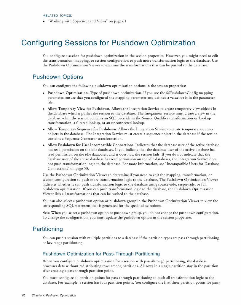
RELATED TOPICS:♦ “Working with Sequences and Views” on page 61
Configuring Sessions for Pushdown OptimizationYou configure a session for pushdown optimization in the session properties. However, you might need to edit the transformation, mapping, or session configuration to push more transformation logic to the database. Use the Pushdown Optimization Viewer to examine the transformations that can be pushed to the database.
Pushdown OptionsYou can configure the following pushdown optimization options in the session properties:
♦ Pushdown Optimization. Type of pushdown optimization. If you use the $$PushdownConfig mapping parameter, ensure that you configured the mapping parameter and defined a value for it in the parameter file.
♦ Allow Temporary View for Pushdown. Allows the Integration Service to create temporary view objects in the database when it pushes the session to the database. The Integration Service must create a view in the database when the session contains an SQL override in the Source Qualifier transformation or Lookup transformation, a filtered lookup, or an unconnected lookup.
♦ Allow Temporary Sequence for Pushdown. Allows the Integration Service to create temporary sequence objects in the database. The Integration Service must create a sequence object in the database if the session contains a Sequence Generator transformation.
♦ Allow Pushdown for User Incompatible Connections. Indicates that the database user of the active database has read permission on the idle databases. If you indicate that the database user of the active database has read permission on the idle databases, and it does not, the session fails. If you do not indicate that the database user of the active database has read permission on the idle databases, the Integration Service does not push transformation logic to the database. For more information, see “Incompatible Users for Database Connections” on page 53.
Use the Pushdown Optimization Viewer to determine if you need to edit the mapping, transformation, or session configuration to push more transformation logic to the database. The Pushdown Optimization Viewer indicates whether it can push transformation logic to the database using source-side, target-side, or full pushdown optimization. If you can push transformation logic to the database, the Pushdown Optimization Viewer lists all transformations that can be pushed to the database.
You can also select a pushdown option or pushdown group in the Pushdown Optimization Viewer to view the corresponding SQL statement that is generated for the specified selections.
Note: When you select a pushdown option or pushdown group, you do not change the pushdown configuration. To change the configuration, you must update the pushdown option in the session properties.
PartitioningYou can push a session with multiple partitions to a database if the partition types are pass-through partitioning or key range partitioning.
Pushdown Optimization for Pass-Through PartitioningWhen you configure pushdown optimization for a session with pass-through partitioning, the database processes data without redistributing rows among partitions. All rows in a single partition stay in the partition after crossing a pass-through partition point.
You must configure all partition points for pass-through partitioning to push all transformation logic to the database. For example, a session has four partition points. You configure the first three partition points for pass-
66 Chapter 4: Pushdown Optimization

through partitioning and the last partition point for hash auto-keys partitioning. The Integration Service pushes all transformation logic to the database, except the transformations at and after the last partition point. The Integration Service processes the transformations at and after the last partition point.
Pushdown Optimization for Key-Range PartitioningWhen you configure pushdown optimization for a session with key-range partitioning at the Source Qualifier transformation, the Integration Service merges all the rows into the first partition and passes empty data for each subsequent partition. The Integration Service creates an SQL statement for each partition. If the Integration Service pushes only part of the transformation logic to the database, it does not redistribute the rows across partitions when it runs the session.
The session must meet the following criteria to enable the Integration Service to push all transformation logic to the database:
♦ The end key range for each partition must equal the start range for the next partition to merge all rows into the first partition. The end key range cannot overlap with the next partition. For example, if the end range for the first partition is 3386, then the start range for the second partition must be 3386.
♦ You must configure the partition point at the Source Qualifier transformation to use key range partitioning and all subsequent partition points to use either hash auto-keys or pass-through partitioning.
Example of Pushdown Optimization for Session with Multiple PartitionsThe following figure shows a mapping that contains a Sorter transformation with hash auto-keys partitioning:
The first key range is 1313 - 3340, and the second key range is 3340 - 9354. The SQL statement merges all the data into the first partition:
SELECT ITEMS.ITEM_ID, ITEMS.ITEM_NAME, ITEMS.ITEM_DESC FROM ITEMS1 ITEMS WHERE (ITEMS.ITEM_ID >= 1313) AND (ITEMS.ITEM_ID < 9354) ORDER BY ITEMS.ITEM_ID
The SQL statement selects items 1313 through 9354, which includes all values in the key range, and merges the data from both partitions into the first partition.
The SQL statement for the second partition passes empty data:
SELECT ITEMS.ITEM_ID, ITEMS.ITEM_NAME, ITEMS.ITEM_DESC FROM ITEMS1 ITEMS WHERE (1 = 0) ORDER BY ITEMS.ITEM_ID
Configuring Sessions for Pushdown Optimization 67

Rules and GuidelinesUse the following rules and guidelines when you configure the Integration Service to push sessions with multiple partitions to a database.
The Integration Service can push a session with multiple partitions to the database in the following situations:
♦ If the session uses pass-through partitioning at the partition point at the Source Qualifier transformation and all subsequent partition points, the Integration Service can push the transformation logic to the database using source-side, target-side, or full pushdown optimization.
♦ If the session uses key range partitioning at the Source Qualifier transformation and contains hash auto-keys or pass-through partitions in downstream partition points, the Integration Service can push the transformation logic to the database using source-side or full pushdown optimization.
If pushdown optimization merges data from multiple partitions of a transformation into the first partition and the Integration Service processes the transformation logic for a downstream transformation, the Integration Service does not redistribute the rows among the partitions in the downstream transformation. It continues to pass the rows to the first partition and pass empty data in the other partitions.
Target Load RulesTarget load rules can affect whether you can push a session to a database.
The following table shows how pushdown optimization works with different target load options. Columns marked with an X indicate that the pushdown optimization type is available for the target option:
Use the following rules and guidelines when you configure the Integration Service to push the target load logic to a database:
♦ If you do not achieve performance gains when you use full pushdown optimization and the source rows are treated as delete or update, use source-side pushdown optimization.
♦ You cannot use full pushdown optimization and treat source rows as delete or update if the session contains a Union transformation and the Integration Service pushes transformation logic to a Sybase database.
Viewing Pushdown GroupsWhen you configure a session for pushdown optimization, the Integration Service generates SQL statements based on the transformation logic. The group of transformations that can be processed as one SQL statement is called a pushdown group.
When you push transformation logic to the database, the Integration Service might create multiple pushdown groups depending on the number of pipelines, sources, targets, and the type of pushdown optimization you use. If the session has multiple partitions, the Integration Service executes an SQL statement for each partition in the group. If you join pipelines, transformations in each pipeline merge into one pushdown group. If the same transformation is part of the transformation logic pushed to two or more targets, the transformation is part of the pushdown group for each target.
You can view pushdown groups using the Pushdown Optimization Viewer. When you view pushdown groups in the Pushdown Optimization Viewer, you can identify the transformations that can be pushed to the database and those that the Integration Service processes. The Pushdown Optimization Viewer also displays messages that you can use to determine how to edit transformations or mappings to push more transformation logic to
Target Option Source Target Full
Insert X X X
Delete X X X
Update as update X X X
Update as insert X X X
Update else insert X X
68 Chapter 4: Pushdown Optimization

the database. The Pushdown Optimization Viewer cannot display the SQL that runs in the session if you use mapping variables or if you configure the session to run on a grid.
When you view the generated SQL, the names of temporary view and sequence objects differ from the names of the view and sequence objects generated during a session. The Integration Service uses a hash function to create a unique name for each sequence and view object it generates.
The following figure shows a mapping displayed in the Pushdown Optimization Viewer. It contains two pushdown groups that can be pushed to the source and target database:
Pipeline 1 and Pipeline 2 originate from different sources and contain transformations that are valid for pushdown optimization. The Integration Service creates a pushdown group for each target, and generates an SQL statement for each pushdown group. Because the two pipelines are joined, the transformations up to and including the Joiner transformation are part of both pipelines and are included in both pushdown groups.
To view pushdown groups, open the Pushdown Optimization Viewer. The Pushdown Optimization Viewer previews the pushdown groups and SQL statements that the Integration Service generates at run time.
To view pushdown groups:
1. In the Workflow Manager, open a session configured for pushdown optimization.
2. On the Mapping tab, select Pushdown Optimization in the left pane or View Pushdown Optimization in the right pane.
The Pushdown Optimization Viewer displays the pushdown groups and the transformations that comprise each group. It displays the SQL statement for each partition if you configure multiple partitions in the pipeline. You can view messages and SQL statements generated for each pushdown group and pushdown option. Pushdown options include None, To Source, To Target, Full, and $$PushdownConfig.
Pipeline 1
Pipeline 2
Pushdown Group 1
Pushdown Group 2
Configuring Sessions for Pushdown Optimization 69

Figure 4-1 shows a mapping containing one pipeline with two partitions that can be pushed to the source database:
3. Select a pushdown option in the Pushdown Optimization Viewer to preview the SQL statements.
The pushdown option in the viewer does not affect the optimization that occurs at run time. To change pushdown optimization for a session, edit the session properties.
4. If you configure the session to use a connection variable, click Preview Result for Connection to select a connection value to preview.
If the session uses a connection variable, you must choose a connection value each time you open the Pushdown Optimization Viewer. The Workflow Manager does not save the value you select, and the Integration Service does not use this value at run time.
If an SQL override contains the $$$SessStartTime variable, the Pushdown Optimization Viewer does not expand this variable when you preview pushdown optimization.
Figure 4-1. Pushdown Optimization Viewer
Number indicates the pushdown group.
Select pushdown groups to view.
SQL statements generated for the pushdown group.
Select a value for the connection variable.
Select the type of optimization.
70 Chapter 4: Pushdown Optimization

C H A P T E R 5
Pushdown Optimization and Transformations
This chapter includes the following topics:
♦ Overview, 71
♦ Aggregator Transformation, 73
♦ Expression Transformation, 73
♦ Filter Transformation, 74
♦ Joiner Transformation, 74
♦ Lookup Transformation, 75
♦ Router Transformation, 76
♦ Sequence Generator Transformation, 77
♦ Sorter Transformation, 78
♦ Source Qualifier Transformation, 78
♦ Target, 79
♦ Union Transformation, 80
♦ Update Strategy Transformation, 81
OverviewWhen you configure pushdown optimization, the Integration Service tries to push each transformation to the database. The following criteria affects whether the Integration Service can push the transformation to the database:
♦ Type of transformation
♦ Location of the transformation in the mapping
♦ Mapping and session configuration for the transformation
♦ The expressions contained in the transformation
The criteria might also affect the type of pushdown optimization that the Integration Service can perform and the type of database to which the transformation can be pushed.
71

The Integration Service can push logic of the following transformations to the database:
♦ Aggregator
♦ Expression
♦ Filter
♦ Joiner
♦ Lookup
♦ Router
♦ Sequence Generator
♦ Sorter
♦ Source Qualifier
♦ Target
♦ Union
♦ Update Strategy
Rules and GuidelinesUse the following rules and guidelines when you configure the Integration Service to push transformation logic to a database.
The Integration Service processes the transformation logic if any of the following conditions are true:
♦ The transformation logic updates a mapping variable and saves it to the repository database.
♦ The transformation contains a variable port.
♦ The transformation meets all of the following criteria:
− Is not a Sorter transformation, Union transformation, or target.
− Is pushed to Microsoft SQL Server, Sybase, or Teradata.
− Is downstream from a Sorter transformation, which is downstream from a Union transformation or contains a distinct sort.
♦ The session is configured to override the default values of input or output ports.
♦ The database does not have an equivalent operator, variable, or function that is used in an expression in the transformation.
♦ The mapping contains too many branches. When you branch a pipeline, the SQL statement required to represent the mapping logic becomes more complex. The Integration Service cannot generate SQL for a mapping that contains more than 64 two-way branches, 43 three-way branches, or 32 four-way branches. If the mapping branches exceed these limitations, the Integration Service processes the downstream transformations.
The Integration Service processes all transformations in the mapping if any of the following conditions are true:
♦ The session is a data profiling or debug session.
♦ The session is configured to log row errors.
72 Chapter 5: Pushdown Optimization and Transformations

Aggregator TransformationThe following table shows the pushdown types for each database to which you can push the Aggregator transformation:
The Integration Service processes the Aggregator transformation if any of the following conditions are true:
♦ The session and mapping is configured for incremental aggregation.
♦ The transformation contains a nested aggregate function.
♦ The transformation contains a conditional clause in an aggregate expression.
♦ The transformation uses a FIRST(), LAST(), MEDIAN(), or PERCENTILE() function in any port expression.
♦ An output port is not an aggregate or a part of the group by port.
♦ The transformation is pushed to Microsoft SQL Server, Sybase, or Teradata and is downstream from a Sorter transformation.
Expression TransformationThe following table shows the pushdown types for each database to which you can push the Expression transformation:
The Integration Service processes the Expression transformation if the transformation calls an unconnected Stored Procedure.
Database Pushdown Type
IBM DB2 Source-side, Full
Microsoft SQL Server Source-side, Full
Netezza Source-side, Full
Oracle Source-side, Full
Sybase ASE Source-side, Full
Teradata Source-side, Full
ODBC Source-side, Full
Database Pushdown Type
IBM DB2 Source-side, Target-side, Full
Microsoft SQL Server Source-side, Target-side, Full
Netezza Source-side, Target-side, Full
Oracle Source-side, Target-side, Full
Sybase ASE Source-side, Target-side, Full
Teradata Source-side, Target-side, Full
ODBC Source-side, Target-side, Full
Aggregator Transformation 73

Filter TransformationThe following table shows the pushdown types for each database to which you can push the Filter transformation:
The Integration Service processes the Filter transformation if the filter expression cannot be pushed to the database. For example, if the filter expression contains an operator that cannot be pushed to the database, the Integration Service does not push the filter expression to the database.
Joiner TransformationThe following table shows the pushdown types for each database to which you can push the Joiner transformation:
The Integration Service processes the Joiner transformation if any of the following conditions are true:
♦ The Integration Service cannot push the master and detail pipelines of the Joiner transformation to the database.
♦ The incoming groups of a Joiner transformation originate from databases on different relational database management systems.
♦ The session is configured to mark all source rows as updates and configured for pushdown optimization to Teradata.
♦ The transformation is configured with an outer join, and the master or detail source is a multi-table join. The Integration Service cannot generate SQL to represent an outer join combined with a multi-table join.
♦ The transformation is configured with a full outer join and configured for pushdown optimization to Sybase.
Database Pushdown Type
IBM DB2 Source-side, Full
Microsoft SQL Server Source-side, Full
Netezza Source-side, Full
Oracle Source-side, Full
Sybase ASE Source-side, Full
Teradata Source-side, Full
ODBC Source-side, Full
Database Pushdown Type
IBM DB2 Source-side, Full
Microsoft SQL Server Source-side, Full
Netezza Source-side, Full
Oracle Source-side, Full
Sybase ASE Source-side, Full
Teradata Source-side, Full
ODBC Source-side, Full
74 Chapter 5: Pushdown Optimization and Transformations

♦ The Integration Service created a view or sequence based on a transformation in the master branch, and the master and detail branches do not come from the same database.
♦ The transformation is pushed to Microsoft SQL Server, Sybase, or Teradata and is downstream from a Sorter transformation, which is downstream from an Aggregator transformation.
♦ The transformation is downstream from a Sorter transformation and is pushed to Microsoft SQL Server, Sybase, or Teradata, and the master and detail tables stem from the same Source Qualifier transformation instance.
Lookup TransformationWhen you configure a Lookup transformation for pushdown optimization, the database performs a lookup on the database lookup table. The following table shows the pushdown types for each database to which you can push the Lookup transformation:
Use the following rules and guidelines when you configure the Integration Service to push Lookup transformation logic to a database:
♦ The database does not use PowerCenter caches when processing transformation logic.
♦ The Integration Service processes all transformations after a pipeline branch when multiple Lookup transformations are present in different branches of pipeline, and the branches merge downstream.
♦ A session configured for target-side pushdown optimization fails if the session requires datatype conversion.
♦ Unlike the Integration Service, a Netezza database may return multiple rows for a single lookup.
♦ Configure pushdown optimization with a view if the Lookup transformation contains an SQL override, contains a filter, or is an unconnected Lookup transformation.
The Integration Service processes the Lookup transformation if any of the following conditions are true:
♦ The transformation is a pipeline lookup.
♦ The transformation uses a dynamic cache.
♦ The transformation is configured to return the first, last, or any matching value. To use pushdown optimization, you must configure the Lookup transformation to report an error on multiple matches.
♦ The transformation requires a view to be created in a database, and the database providing the lookup input is different from the database where the view is created.
♦ The transformation is pushed to Microsoft SQL Server, Sybase, or Teradata and is downstream from a Sorter transformation, which is downstream from an Aggregator transformation.
♦ The session is configured to mark all source rows as updates and configured for pushdown optimization to Teradata.
♦ The session is configured for source-side pushdown optimization and the lookup table and source table are in different relational database management systems.
Database Pushdown Type
IBM DB2 Source-side, Target-side, Full
Microsoft SQL Server Source-side, Full
Netezza Source-side, Full
Oracle Source-side, Target-side, Full
Sybase ASE Source-side, Full
Teradata Source-side, Full
ODBC Source-side, Full
Lookup Transformation 75
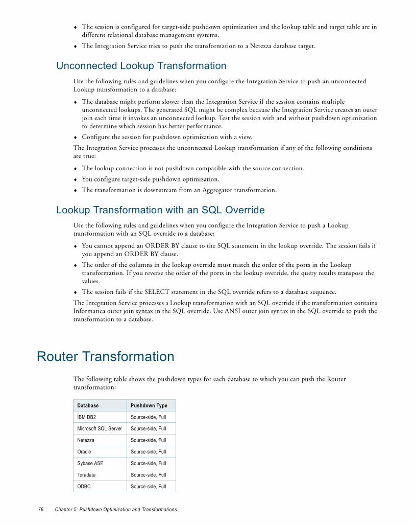
♦ The session is configured for target-side pushdown optimization and the lookup table and target table are in different relational database management systems.
♦ The Integration Service tries to push the transformation to a Netezza database target.
Unconnected Lookup TransformationUse the following rules and guidelines when you configure the Integration Service to push an unconnected Lookup transformation to a database:
♦ The database might perform slower than the Integration Service if the session contains multiple unconnected lookups. The generated SQL might be complex because the Integration Service creates an outer join each time it invokes an unconnected lookup. Test the session with and without pushdown optimization to determine which session has better performance.
♦ Configure the session for pushdown optimization with a view.
The Integration Service processes the unconnected Lookup transformation if any of the following conditions are true:
♦ The lookup connection is not pushdown compatible with the source connection.
♦ You configure target-side pushdown optimization.
♦ The transformation is downstream from an Aggregator transformation.
Lookup Transformation with an SQL OverrideUse the following rules and guidelines when you configure the Integration Service to push a Lookup transformation with an SQL override to a database:
♦ You cannot append an ORDER BY clause to the SQL statement in the lookup override. The session fails if you append an ORDER BY clause.
♦ The order of the columns in the lookup override must match the order of the ports in the Lookup transformation. If you reverse the order of the ports in the lookup override, the query results transpose the values.
♦ The session fails if the SELECT statement in the SQL override refers to a database sequence.
The Integration Service processes a Lookup transformation with an SQL override if the transformation contains Informatica outer join syntax in the SQL override. Use ANSI outer join syntax in the SQL override to push the transformation to a database.
Router TransformationThe following table shows the pushdown types for each database to which you can push the Router transformation:
Database Pushdown Type
IBM DB2 Source-side, Full
Microsoft SQL Server Source-side, Full
Netezza Source-side, Full
Oracle Source-side, Full
Sybase ASE Source-side, Full
Teradata Source-side, Full
ODBC Source-side, Full
76 Chapter 5: Pushdown Optimization and Transformations

You can use source-side pushdown when all output groups merge into one transformation that can be pushed to the source database.
The Integration Service processes the Router transformation if the router expression cannot be pushed to the database. For example, if the expression contains an operator that cannot be pushed to the database, the Integration Service does not push the expression to the database.
Sequence Generator TransformationThe following table shows the pushdown types for each database to which you can push the Sequence Generator transformation:
The Integration Service processes the Sequence Generator transformation if any of the following conditions are true:
♦ The transformation is reusable.
♦ The transformation is connected to multiple targets.
♦ The transformation connects the CURRVAL port.
♦ The transformation provides sequence values to a transformation downstream from a Source Qualifier transformation that is configured to select distinct rows.
♦ The Integration Service cannot push all of the logic for the Sequence Generator transformation to the database. For example, a Sequence Generator transformation creates sequence values that are supplied to two branches of a pipeline. When you configure pushdown optimization, the database can create sequence values for only one pipeline branch. When the Integration Service cannot push all of the Sequence Generator logic to the database, the following message appears:
Pushdown optimization stops at the transformation <transformation name> because the upstream Sequence Generator <Sequence Generator transformation name> cannot be pushed entirely to the database.
♦ The pipeline branches before the Sequence Generator transformation and then joins back together after the Sequence Generator transformation.
♦ The pipeline branches after the Sequence Generator transformation and does not join back together.
♦ A sequence value passes through an Aggregator, a Filter, a Joiner, a Sorter, or a Union transformation.
♦ The database where the sequence object is created must be the active database or of the same database type as the active database.
The Integration Service processes a transformation downstream from the Sequence Generator transformation if it uses the NEXTVAL port of the Sequence Generator transformation in CASE expressions and is configured for pushdown optimization to IBM DB2.
Database Pushdown Type
IBM DB2 Source-side, Target-side, Full
Microsoft SQL Server Not supported
Netezza Not supported
Oracle Source-side, Target-side, Full
Sybase Not supported
Teradata Not supported
ODBC Not supported
Sequence Generator Transformation 77

Sorter TransformationThe following table shows the pushdown types for each database to which you can push the Sorter transformation:
Use the following rules and guidelines when you configure the Integration Service to push Sorter transformation logic to a database. The Integration Service pushes the Sorter transformation to the database and processes downstream transformations when the Sorter transformation is configured for a distinct sort and is pushed to a Microsoft SQL Server, Sybase, or Teradata database.
The Integration Service processes the Sorter Qualifier transformation logic when the transformation is downstream from a Union transformation and the port used as a sort key in the Sorter transformation is not projected from the Union transformation to the Sorter transformation.
Source Qualifier TransformationThe following table shows the pushdown types for each database to which you can push the Source Qualifier transformation:
Use the following rules and guidelines when you configure the Integration Service to push Source Qualifier transformation logic to a database:
♦ Qualify the table name that you enter for a source filter or user-defined join when the Sequence Generator transformation is in the idle connection in a downstream Union transformation, Joiner transformation, or target, and the other connections are of a different database type. If you do not qualify the table name in this case, the Integration Service does not push all transformations to the database.
RELATED TOPICS:♦ “Qualifying Names of Tables in Idle Databases” on page 53
Database Pushdown Type
IBM DB2 Source-side, Full
Microsoft SQL Server Source-side, Full
Netezza Source-side, Full
Oracle Source-side, Full
Sybase ASE Source-side, Full
Teradata Source-side, Full
ODBC Source-side, Full
Database Pushdown Type
IBM DB2 Source-side, Full
Microsoft SQL Server Source-side, Full
Netezza Source-side, Full
Oracle Source-side, Full
Sybase ASE Source-side, Full
Teradata Source-side, Full
ODBC Source-side, Full
78 Chapter 5: Pushdown Optimization and Transformations

The Integration Service processes the Source Qualifier transformation logic when any of the following conditions are true:
♦ The transformation contains Informatica outer join syntax in the SQL override or a user-defined join. Use ANSI outer join syntax in the SQL override to enable the Integration Service to push the Source Qualifier transformation to the database.
♦ The source is configured for database partitioning.
♦ The source is an Oracle source that uses an XMLType datatype.
Source Qualifier Transformation with an SQL OverrideUse the following rules and guidelines when you configure pushdown optimization for a session containing a Source Qualifier transformation with an SQL override:
♦ The SELECT statement in a custom SQL query must list the port names in the order in which they appear in the transformation. If the ports are not in the correct order, the session can fail or output unexpected results.
♦ Configure the session for pushdown optimization with a view.
♦ The session fails if the SELECT statement in the SQL override refers to a database sequence.
♦ The session fails if the SQL override contains an ORDER BY clause and you push the Source Qualifier transformation logic to an IBM DB2, a Microsoft SQL Server, a Sybase ASE, or a Teradata database.
♦ If a Source Qualifier transformation is configured to select distinct values and contains an SQL override, the Integration Service ignores the distinct configuration.
♦ If the session contains multiple partitions, specify the SQL override for all partitions.
♦ Test the SQL override query on the source database before you push it to the database because PowerCenter does not validate the override SQL syntax. The session fails if the SQL syntax is not compatible with the source database.
TargetThe following table shows the pushdown types for each database to which you can push the target logic:
The Integration Service processes the target logic when you configure the session for full pushdown optimization and any of the following conditions are true:
♦ The target includes a target update override.
♦ The session is configured for constraint-based loading, and the target load order group contains more than one target.
♦ The session uses an external loader.
Database Pushdown Type
IBM DB2 Target-side, Full
Microsoft SQL Server Target-side, Full
Netezza Target-side, Full
Oracle Target-side, Full
Sybase ASE Target-side, Full
Teradata Target-side, Full
ODBC Target-side, Full
Target 79

♦ A view or sequence generator was created in an idle database.
If you configure full pushdown optimization and the target and source connections are incompatible, the Integration Service cannot push the all transformation logic to one database. Instead, it pushes as much transformation logic as possible to the source database and pushes any remaining transformation logic to the target database if it is possible.
The Integration Service processes the target logic when you configure the session for target-side pushdown optimization and any of the following conditions are true:
♦ The target includes a target update override.
♦ The target is configured for database partitioning.
♦ The session is configured for bulk loading and the target is IBM DB2, Microsoft SQL Server, Oracle, or Sybase ASE.
♦ The session uses an external loader. Use source-side pushdown optimization with an external loader to enable the Integration Service to push the transformation logic to the source database.
Union TransformationThe following table shows the pushdown types for each database to which you can push the Union transformation:
The Integration Service processes the Union transformation logic when any of the following conditions are true:
♦ The Integration Service cannot push all input groups to the source database.
♦ The input groups do not originate from the same relational database management system.
♦ One of the input pipelines of the Union transformation contains either a distinct union or sorter.
♦ The transformation is downstream from a transformation that required a view or sequence generator to be created in a database and the connections are on different databases.
Database Pushdown Type
IBM DB2 Source-side, Full
Microsoft SQL Server Source-side, Full
Netezza Source-side, Full
Oracle Source-side, Full
Sybase ASE Source-side, Full
Teradata Source-side, Full
ODBC Source-side, Full
80 Chapter 5: Pushdown Optimization and Transformations

Update Strategy TransformationThe following table shows the pushdown types for each database to which you can push the Update Strategy transformation:
Use the following rules and guidelines when you configure the Integration Service to push Update Strategy transformation logic to a database:
♦ The generated SQL for an Update Strategy transformation with an update operation can be complex. Run the session with and without pushdown optimization to determine which configuration is faster.
♦ If there are multiple operations to the same row, the Integration Service and database can process the operations differently. To ensure that new rows are not deleted or updated when pushed to a database, source rows are processed in the following order: delete transactions, update transactions, and then insert transactions.
♦ If the transformation contains more than one insert, update, or delete operation, the Integration Service generates and runs the insert, update, and delete SQL statements serially. The Integration Service runs the three statements even if they are not required. This might decrease performance.
♦ The Integration Service ignores rejected rows when using full pushdown optimization. It does not write reject rows to a reject file.
The Integration Service processes the Update Strategy transformation if any of the following conditions are true:
♦ If the Integration Service cannot push the update strategy expression to the database. For example, if the expression contains an operator that cannot be pushed to the database, the Integration Service does not push the expression to the database.
♦ The transformation uses operations other than the insert operation and the Integration Service cannot push all transformation logic to the database.
♦ The update strategy expression returns a value that is not numeric and not Boolean.
Database Pushdown Type
IBM DB2 Full
Microsoft SQL Server Full
Netezza Full
Oracle Full
Sybase ASE Full
Teradata Full
ODBC Full
Update Strategy Transformation 81

82 Chapter 5: Pushdown Optimization and Transformations

C H A P T E R 6
Real-time Processing
This chapter includes the following topics:
♦ Overview, 83
♦ Understanding Real-time Data, 84
♦ Configuring Real-time Sessions, 86
♦ Terminating Conditions, 86
♦ Flush Latency, 87
♦ Commit Type, 88
♦ Message Recovery, 88
♦ Recovery File, 89
♦ Recovery Table, 91
♦ Recovery Queue and Recovery Topic, 92
♦ Recovery Ignore List, 93
♦ Stopping Real-time Sessions, 93
♦ Restarting and Recovering Real-time Sessions, 94
♦ Rules and Guidelines, 95
♦ Real-time Processing Example, 96
♦ Informatica Real-time Products, 97
OverviewThis chapter contains general information about real-time processing. Real-time processing behavior depends on the real-time source. Exceptions are noted in this chapter or are described in the corresponding product documentation. For more information about real-time processing for your Informatica real-time product, see the Informatica product documentation. For more information about real-time processing for PowerExchange, see PowerExchange Interfaces for PowerCenter.
You can use PowerCenter to process data in real time. Real-time processing is on-demand processing of data from real-time sources. A real-time session reads, processes, and writes data to targets continuously. By default, a session reads and writes bulk data at scheduled intervals unless you configure the session for real-time processing.
83

To process data in real time, the data must originate from a real-time source. Real-time sources include JMS, WebSphere MQ, TIBCO, webMethods, MSMQ, SAP, and web services. You might want to use real-time processing for processes that require immediate access to dynamic data, such as financial data.
To understand real-time processing with PowerCenter, you need to be familiar with the following concepts:
♦ Real-time data. Real-time data includes messages and messages queues, web services messages, and changes from a PowerExchange change data capture source. Real-time data originates from a real-time source.
♦ Real-time sessions. A real-time session is a session that processes real-time source data. A session is real-time if the Integration Service generates a real-time flush based on the flush latency configuration and all transformations propagate the flush to the targets. Latency is the period of time from when source data changes on a source to when a session writes the data to a target.
♦ Real-time properties. Real-time properties determine when the Integration Service processes the data and commits the data to the target.
− Terminating conditions. Terminating conditions determine when the Integration Service stops reading data from the source and ends the session if you do not want the session to run continuously.
− Flush latency. Flush latency determines how often the Integration Service flushes real-time data from the source.
− Commit type. The commit type determines when the Integration Service commits real-time data to the target.
♦ Message recovery. If the real-time session fails, you can recover messages. When you enable message recovery for a real-time session, the Integration Service stores source messages or message IDs in a recovery file or table. If the session fails, you can run the session in recovery mode to recover messages the Integration Service could not process.
Understanding Real-time DataYou can process the following types of real-time data:
♦ Messages and message queues. Process messages and message queues from WebSphere MQ, JMS, MSMQ, SAP, TIBCO, and webMethods sources. You can read from messages and message queues. You can write to messages, messaging applications, and message queues.
♦ Web service messages. Receive a message from a web service client through the Web Services Hub and transform the data. You can write the data to a target or send a message back to a web service client.
♦ Change data from PowerExchange change data capture sources. Extract change data that represent changes to a relational database or file source from the change stream and write to a target.
Messages and Message QueuesThe Integration Service uses the messaging and queueing architecture to process real-time data. It can read messages from a message queue, process the message data, and write messages to a message queue.
You can also write messages to other messaging applications. For example, the Integration Service can read messages from a JMS source and write the data to a TIBCO target.
The following figure shows an example of how the messaging application and the Integration Service process messages from a message queue:
Messaging Application
Integration ServiceMessage Queue
Source
MessageMessageMessage
Message Queue
Target
MessageMessageMessage
1 2
34
84 Chapter 6: Real-time Processing
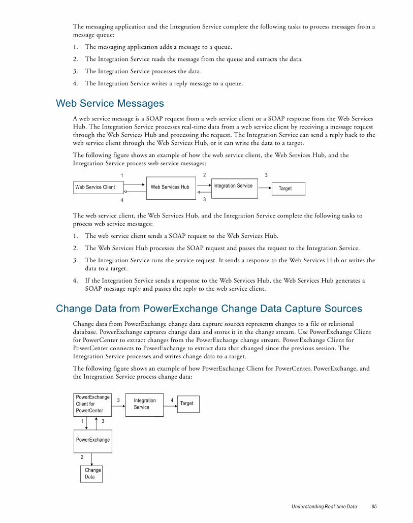
The messaging application and the Integration Service complete the following tasks to process messages from a message queue:
1. The messaging application adds a message to a queue.
2. The Integration Service reads the message from the queue and extracts the data.
3. The Integration Service processes the data.
4. The Integration Service writes a reply message to a queue.
Web Service MessagesA web service message is a SOAP request from a web service client or a SOAP response from the Web Services Hub. The Integration Service processes real-time data from a web service client by receiving a message request through the Web Services Hub and processing the request. The Integration Service can send a reply back to the web service client through the Web Services Hub, or it can write the data to a target.
The following figure shows an example of how the web service client, the Web Services Hub, and the Integration Service process web service messages:
The web service client, the Web Services Hub, and the Integration Service complete the following tasks to process web service messages:
1. The web service client sends a SOAP request to the Web Services Hub.
2. The Web Services Hub processes the SOAP request and passes the request to the Integration Service.
3. The Integration Service runs the service request. It sends a response to the Web Services Hub or writes the data to a target.
4. If the Integration Service sends a response to the Web Services Hub, the Web Services Hub generates a SOAP message reply and passes the reply to the web service client.
Change Data from PowerExchange Change Data Capture SourcesChange data from PowerExchange change data capture sources represents changes to a file or relational database. PowerExchange captures change data and stores it in the change stream. Use PowerExchange Client for PowerCenter to extract changes from the PowerExchange change stream. PowerExchange Client for PowerCenter connects to PowerExchange to extract data that changed since the previous session. The Integration Service processes and writes change data to a target.
The following figure shows an example of how PowerExchange Client for PowerCenter, PowerExchange, and the Integration Service process change data:
Web Service Client Integration ServiceWeb Services Hub Target
1 2
3
3
4
Change Data
PowerExchange
1 3
2
3 TargetPowerExchange Client for PowerCenter
Integration Service
4
Understanding Real-t ime Data 85
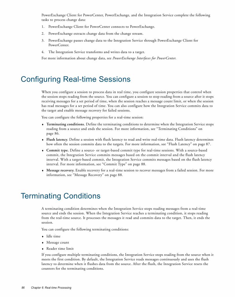
PowerExchange Client for PowerCenter, PowerExchange, and the Integration Service complete the following tasks to process change data:
1. PowerExchange Client for PowerCenter connects to PowerExchange.
2. PowerExchange extracts change data from the change stream.
3. PowerExchange passes change data to the Integration Service through PowerExchange Client for PowerCenter.
4. The Integration Service transforms and writes data to a target.
For more information about change data, see PowerExchange Interfaces for PowerCenter.
Configuring Real-time SessionsWhen you configure a session to process data in real time, you configure session properties that control when the session stops reading from the source. You can configure a session to stop reading from a source after it stops receiving messages for a set period of time, when the session reaches a message count limit, or when the session has read messages for a set period of time. You can also configure how the Integration Service commits data to the target and enable message recovery for failed sessions.
You can configure the following properties for a real-time session:
♦ Terminating conditions. Define the terminating conditions to determine when the Integration Service stops reading from a source and ends the session. For more information, see “Terminating Conditions” on page 86.
♦ Flush latency. Define a session with flush latency to read and write real-time data. Flush latency determines how often the session commits data to the targets. For more information, see “Flush Latency” on page 87.
♦ Commit type. Define a source- or target-based commit type for real-time sessions. With a source-based commit, the Integration Service commits messages based on the commit interval and the flush latency interval. With a target-based commit, the Integration Service commits messages based on the flush latency interval. For more information, see “Commit Type” on page 88.
♦ Message recovery. Enable recovery for a real-time session to recover messages from a failed session. For more information, see “Message Recovery” on page 88.
Terminating ConditionsA terminating condition determines when the Integration Service stops reading messages from a real-time source and ends the session. When the Integration Service reaches a terminating condition, it stops reading from the real-time source. It processes the messages it read and commits data to the target. Then, it ends the session.
You can configure the following terminating conditions:
♦ Idle time
♦ Message count
♦ Reader time limit
If you configure multiple terminating conditions, the Integration Service stops reading from the source when it meets the first condition. By default, the Integration Service reads messages continuously and uses the flush latency to determine when it flushes data from the source. After the flush, the Integration Service resets the counters for the terminating conditions.
86 Chapter 6: Real-time Processing

Idle TimeIdle time is the amount of time in seconds the Integration Service waits to receive messages before it stops reading from the source. -1 indicates an infinite period of time.
For example, if the idle time for a JMS session is 30 seconds, the Integration Service waits 30 seconds after reading from JMS. If no new messages arrive in JMS within 30 seconds, the Integration Service stops reading from JMS. It processes the messages and ends the session.
Message CountMessage count is the number of messages the Integration Service reads from a real-time source before it stops reading from the source. -1 indicates an infinite number of messages.
For example, if the message count in a JMS session is 100, the Integration Service stops reading from the source after it reads 100 messages. It processes the messages and ends the session.
Note: The name of the message count terminating condition depends on the Informatica product. For example, the message count for PowerExchange for SAP NetWeaver is called Packet Count. The message count for PowerExchange Client for PowerCenter is called UOW Count.
Reader Time LimitReader time limit is the amount of time in seconds that the Integration Service reads source messages from the real-time source before it stops reading from the source. Use reader time limit to read messages from a real-time source for a set period of time. 0 indicates an infinite period of time.
For example, if you use a 10 second time limit, the Integration Service stops reading from the messaging application after 10 seconds. It processes the messages and ends the session.
Flush LatencyUse flush latency to run a session in real time. Flush latency determines how often the Integration Service flushes data from the source. For example, if you set the flush latency to 10 seconds, the Integration Service flushes data from the source every 10 seconds.
For change data from a PowerExchange change data capture source, the flush latency interval is determined by the flush latency and the unit of work (UOW) count attributes. For more information, see PowerExchange Interfaces for PowerCenter.
The Integration Service uses the following process when it reads data from a real-time source and the session is configured with flush latency:
1. The Integration Service reads data from the source.
The flush latency interval begins when the Integration Service reads the first message from the source.
2. At the end of the flush latency interval, the Integration Service stops reading data from the source.
3. The Integration Service processes messages and writes them to the target.
4. The Integration Service reads from the source again until it reaches the next flush latency interval.
Configure flush latency in seconds. The default value is zero, which indicates that the flush latency is disabled and the session does not run in real time.
Configure the flush latency interval depending on how dynamic the data is and how quickly users need to access the data. If data is outdated quickly, such as financial trading information, then configure a lower flush latency interval so the target tables are updated as close as possible to when the changes occurred. For example, users need updated financial data every few minutes. However, they need updated customer address changes only
Flush Latency 87

once a day. Configure a lower flush latency interval for financial data and a higher flush latency interval for address changes.
Use the following rules and guidelines when you configure flush latency:
♦ The Integration Service does not buffer messages longer than the flush latency interval.
♦ The lower you set the flush latency interval, the more frequently the Integration Service commits messages to the target.
♦ If you use a low flush latency interval, the session can consume more system resources.
If you configure a commit interval, then a combination of the flush latency and the commit interval determines when the data is committed to the target.
Commit Type The Integration Service commits data to the target based on the flush latency and the commit type. You can configure a session to use the following commit types:
♦ Source-based commit. When you configure a source-based commit, the Integration Service commits data to the target using a combination of the commit interval and the flush latency interval. The first condition the Integration Service meets triggers the end of the flush latency period. After the flush, the counters are reset.
For example, you set the flush latency to five seconds and the source-based commit interval to 1,000 messages. The Integration Service commits messages to the target either after reading 1,000 messages from the source or after five seconds.
♦ Target-based commit. When you configure a target-based commit, the Integration Service ignores the commit interval and commits data to the target based on the flush latency interval.
When writing to targets in a real-time session, the Integration Service processes commits serially and commits data to the target in real time. It does not store data in the DTM buffer memory.
RELATED TOPICS:♦ “Commit Points” on page 99
Message RecoveryWhen you enable message recovery for a real-time session, the Integration Service can recover unprocessed messages from a failed session. The Integration Service stores source messages or message IDs in a recovery file, recovery table, recovery queue, or recovery topic. If the session fails, run the session in recovery mode to recover the messages the Integration Service did not process.
Depending on the real-time source and the target type, the messages or message IDs are stored in the following storage types:
♦ Recovery file. Messages or message IDs are stored in a designated local recovery file. A session with a real-time source and a non-relational or non-queue target uses the recovery file. For more information, see “Recovery File” on page 89.
♦ Recovery table. Message IDs are stored in a recovery table in the target database. A session with a JMS or WebSphere MQ source and a relational target uses the recovery table. For more information, see “Recovery Table” on page 91.
♦ Recovery queue and recovery topic. Message IDs are stored in a recovery queue or recovery topic. A session with a JMS or WebSphere MQ source and a JMS or WebSphere MQ target uses the recovery queue. A session with a JMS or WebSphere MQ source and a topic target uses the recovery topic. For more information, see “Recovery Queue and Recovery Topic” on page 92.
88 Chapter 6: Real-time Processing

A session can use a combination of the storage types. For example, a session with a JMS and TIBCO source uses a recovery file and recovery table.
When you recover a real-time session, the Integration Service restores the state of operation from the point of interruption. It reads and processes the messages in the recovery file, recovery table, recovery queue, or recovery topic. Then, it ends the session.
During recovery, the terminating conditions do not affect the messages the Integration Service reads from the recovery file, recovery table, recovery queue, or recovery topic. For example, if you specified message count and idle time for the session, the conditions apply to the messages the Integration Service reads from the source, not the recovery file, recovery table, recovery queue, or recovery topic.
In addition to the storage types above, the Integration Service uses a recovery ignore list if the session fails under certain conditions. For more information, see “Recovery Ignore List” on page 93.
Sessions with MSMQ sources, web service messages, or change data from a PowerExchange change data capture source use a different recovery strategy. For more information, see the PowerExchange for MSMQ User Guide, PowerCenter Web Services Provider Guide, or PowerExchange Interfaces for PowerCenter.
PrerequisitesComplete the following prerequisites before you enable message recovery for sessions with a JMS or WebSphere MQ source and a JMS or WebSphere MQ target:
♦ Create the recovery queue in the JMS provider or WebSphere MQ. Or, create the recovery topic in the JMS provider.
♦ Create the recovery queue under the same queue manager as the message queue so the commit scope is the same.
♦ Configure the recovery queue to be persistent. If the recovery queue is not persistent, data duplication can occur.
If you do not configure the prerequisites, the Integration Service stores recovery information in a recovery file instead of a recovery queue or recovery topic.
Steps to Enable Message RecoveryComplete the following steps to enable message recovery for sessions:
1. In the session properties, select Resume from Last Checkpoint as the recovery strategy.
2. Specify a recovery cache directory in the session properties at each partition point.
The Integration Service stores messages in the location indicated by the recovery cache directory. The default value recovery cache directory is $PMCacheDir.
Recovery FileThe Integration Service stores messages or message IDs in a recovery file for real-time sessions that are enabled for recovery and include the following source and target types:
♦ JMS source with non-relational, non-JMS, or non-WebSphere MQ targets
♦ WebSphere MQ source with non-relational, non-JMS, or non-WebSphere MQ targets
♦ SAP R/3 source and all targets
♦ webMethods source and all targets
♦ TIBCO source and all targets
Recovery File 89
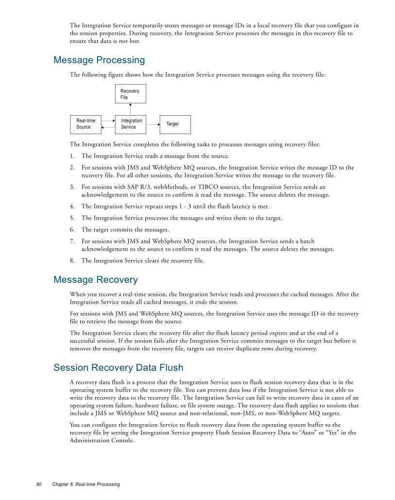
The Integration Service temporarily stores messages or message IDs in a local recovery file that you configure in the session properties. During recovery, the Integration Service processes the messages in this recovery file to ensure that data is not lost.
Message ProcessingThe following figure shows how the Integration Service processes messages using the recovery file:
The Integration Service completes the following tasks to processes messages using recovery files:
1. The Integration Service reads a message from the source.
2. For sessions with JMS and WebSphere MQ sources, the Integration Service writes the message ID to the recovery file. For all other sessions, the Integration Service writes the message to the recovery file.
3. For sessions with SAP R/3, webMethods, or TIBCO sources, the Integration Service sends an acknowledgement to the source to confirm it read the message. The source deletes the message.
4. The Integration Service repeats steps 1 - 3 until the flush latency is met.
5. The Integration Service processes the messages and writes them to the target.
6. The target commits the messages.
7. For sessions with JMS and WebSphere MQ sources, the Integration Service sends a batch acknowledgement to the source to confirm it read the messages. The source deletes the messages.
8. The Integration Service clears the recovery file.
Message RecoveryWhen you recover a real-time session, the Integration Service reads and processes the cached messages. After the Integration Service reads all cached messages, it ends the session.
For sessions with JMS and WebSphere MQ sources, the Integration Service uses the message ID in the recovery file to retrieve the message from the source.
The Integration Service clears the recovery file after the flush latency period expires and at the end of a successful session. If the session fails after the Integration Service commits messages to the target but before it removes the messages from the recovery file, targets can receive duplicate rows during recovery.
Session Recovery Data FlushA recovery data flush is a process that the Integration Service uses to flush session recovery data that is in the operating system buffer to the recovery file. You can prevent data loss if the Integration Service is not able to write the recovery data to the recovery file. The Integration Service can fail to write recovery data in cases of an operating system failure, hardware failure, or file system outage. The recovery data flush applies to sessions that include a JMS or WebSphere MQ source and non-relational, non-JMS, or non-WebSphere MQ targets.
You can configure the Integration Service to flush recovery data from the operating system buffer to the recovery file by setting the Integration Service property Flush Session Recovery Data to “Auto” or “Yes” in the Administration Console.
Real-time Source
Integration Service
Recovery File
Target
90 Chapter 6: Real-time Processing

Recovery TableThe Integration Service stores message IDs in a recovery table for real-time sessions that are enabled for recovery and include the following source and target types:
♦ JMS source with relational targets
♦ WebSphere MQ source with relational targets
The Integration Service temporarily stores message IDs and commit numbers in a recovery table on each target database. The commit number indicates the number of commits that the Integration Service committed to the target. During recovery, the Integration Service uses the commit number to determine if it wrote the same amount of messages to all targets. The messages IDs and commit numbers are verified against the recovery table to ensure that no data is lost or duplicated.
Note: The source must use unique message IDs and provide access to the messages through the message ID.
PM_REC_STATE TableWhen the Integration Service runs a real-time session that uses the recovery table and has recovery enabled, it creates a recovery table, PM_REC_STATE, on the target database to store message IDs and commit numbers. When the Integration Service recovers the session, it uses information in the recovery tables to determine if it needs to write the message to the target table.
RELATED TOPICS:♦ “Target Recovery Tables” on page 125
Message ProcessingThe following figure shows how the Integration Service processes messages using the recovery table:
The Integration Service completes the following tasks to process messages using recovery tables:
1. The Integration Service reads one message at a time until the flush latency is met.
2. The Integration Service stops reading from the source. It processes the messages and writes them to the target.
3. The Integration Service writes the message IDs, commit numbers, and the transformation states to the recovery table on the target database and writes the messages to the target simultaneously.
4. When the target commits the messages, the Integration Service sends an acknowledgement to the real-time source to confirm that all messages were processed and written to the target.
5. The Integration Service continues to read messages from the source.
If the session has multiple partitions, the tasks apply to each partition.
Message RecoveryWhen you recover a real-time session, the Integration Service uses the message ID and the commit number in the recovery table to determine whether it committed messages to all targets.
Real-time Source
Integration Service
Recovery Table
Target Table
Target Database
Recovery Table 91

The Integration Service commits messages to all targets if the message ID exists in the recovery table and all targets have the same commit number. During recovery, the Integration Service sends an acknowledgement to the source that it processed the message.
The Integration Service does not commit messages to all targets if the targets have different commit numbers. During recovery, the Integration Service reads the message IDs and the transformation state from the recovery table. It processes messages and writes them to the targets that did not have the message. When the Integration Service reads all messages from the recovery table, it ends the session.
If the session fails before the Integration Service commits messages to all targets and you restart the session in cold start mode, targets can receive duplicate rows.
Recovery Queue and Recovery TopicThe Integration Service stores message IDs in a recovery queue or recovery topic for real-time sessions that are enabled for recovery and include the following source and target types:
♦ JMS source with JMS or WebSphere MQ targets
♦ WebSphere MQ source with JMS or WebSphere MQ targets
The Integration Service temporarily stores message IDs and commit numbers in a recovery queue or recovery topic that you created in the JMS provider or in WebSphere MQ. The commit number indicates the number of commits that the Integration Service committed to the target. During recovery, the Integration Service uses the commit number to determine if it wrote the same amount of messages to all targets. The messages IDs and commit numbers are verified against the recovery queue or recovery topic to ensure that no data is lost or duplicated.
The Integration Service uses the same recovery queue or recovery topic for all queue targets in each session. Create multiple recovery queues or recovery topics for sessions to improve performance.
If you do not specify the recovery queue or recovery topic name in the session properties or in the JMS connection object, the Integration Service stores recovery information in the recovery file. For optimal performance, configure the recovery queue or recovery topic name instead of the recovery file.
RELATED TOPICS:“Recovery Table” on page 91
Message ProcessingThe following figure shows how the Integration Service processes messages using the recovery queue:
The Integration Service processes messages using the recovery queue or recovery topic similar to how it processes messages using the recovery table. The Integration Service writes recovery information to the recovery queue or recovery topic instead of the recovery table.
Real-time Source
Integration Service
Recovery Queue
Message Queue
Queue Manager
92 Chapter 6: Real-time Processing

Message RecoveryThe Integration Service recovers messages from the recovery queue or recovery topic similar to how it recovers messages from the recovery table. The Integration Service retrieves recovery information from the recovery queue or recovery topic instead of from the recovery table.
Recovery Ignore ListThe Integration Service writes recovery information to a recovery ignore list when a session with a JMS or WebSphere MQ source fails. The Integration Service writes recovery information to the list if there is a chance that the source did not receive an acknowledgement. For example, the session fails before the Integration Service sends an acknowledgement to the source but after it writes messages to the target. In this case, the source can rollback the current transaction, but the messages in that transaction may not be immediately available. If the messages are included in the recovery session, data duplication can occur. To prevent data duplication, the Integration Service creates the recovery ignore list.
The recovery ignore list stores message IDs that the Integration Service wrote to the target for the failed session. The Integration Service creates the recovery ignore list in the storage type that is used for that session, such as the recovery file, recovery table, recovery queue, or recovery topic. During recovery, the Integration Service uses the recovery ignore list and the storage type to determine if it wrote the messages to the target. It verifies the messages IDs against the recovery ignore list and the storage type to ensure that no data is duplicated.
When the session fails, the Integration Service writes the message to the recovery ignore list and adds a time stamp. By default, the Integration Service deletes the message from the recovery ignore list one hour after the time stamp. If the Integration Service finds the message in the source within the default time period, it deletes the message from the recovery ignore list.
If you restart a stopped or failed session in cold start mode, targets may receive duplicate rows. Restart the session with recovery to prevent data duplication. Or, restart the session in cold start mode if you can ensure that the messages that were in the recovery ignore list are removed from the source. Use the session log to view the message IDs. The Integration Service writes the message IDs from the recovery ignore list to the session log if you configure verbose data tracing.
Stopping Real-time SessionsA real-time session runs continuously unless it fails or you manually stop it. You can stop a session by issuing a stop command in pmcmd or from the Workflow Monitor. You might want to stop a session to perform routine maintenance.
When you stop a real-time session, the Integration Service processes messages in the pipeline based on the following real-time sources:
♦ JMS and WebSphere MQ. The Integration Service processes messages it read up until you issued the stop. It writes messages to the targets.
♦ MSMQ, SAP, TIBCO, webMethods, and web service messages. The Integration Service does not process messages if you stop a session before the Integration Service writes all messages to the target.
When you stop a real-time session with a JMS or a WebSphere MQ source, the Integration Service performs the following tasks:
1. The Integration Service stops reading messages from the source.
If you stop a real-time recovery session, the Integration Service stops reading from the source after it recovers all messages.
Recovery Ignore List 93

2. The Integration Service processes messages in the pipeline and writes to the targets.
3. The Integration Service sends an acknowledgement to the source.
4. The Integration Service clears the recovery table or recovery file to avoid data duplication when you restart the session.
When you restart the session, the Integration Service starts reading from the source. It restores the session and transformation state of operation to resume the session from the point of interruption.
Restarting and Recovering Real-time SessionsYou can resume a stopped or failed real-time session. To resume a session, you must restart or recover the session. The Integration Service can recover a session automatically if you enabled the session for automatic task recovery.
The following sections describe recovery information that is specific to real-time sessions.
RELATED TOPICS:♦ “Workflow Recovery” on page 123
Restarting Real-time SessionsWhen you restart a session, the Integration Service resumes the session based on the real-time source. Depending on the real-time source, it restarts the session with or without recovery.
You can restart a task or workflow in cold start mode. When you restart a task or workflow in cold start mode, the Integration Service discards the recovery information and restarts the task or workflow.
Recovering Real-time SessionsIf you enabled session recovery, you can recover a failed or aborted session. When you recover a session, the Integration Service continues to process messages from the point of interruption. The Integration Service recovers messages according to the real-time source.
The Integration Service uses the following session recovery types:
♦ Automatic recovery. The Integration Service restarts the session if you configured the workflow to automatically recover terminated tasks. The Integration Service recovers any unprocessed data and restarts the session regardless of the real-time source.
♦ Manual recovery. Use a Workflow Monitor or Workflow Manager menu command or pmcmd command to recover the session. For some real-time sources, you must recover the session before you restart it or the Integration Service will not process messages from the failed session.
94 Chapter 6: Real-time Processing

Restart and Recover CommandsYou can restart or recover a session in the Workflow Manager, Workflow Monitor, or pmcmd. The Integration Service resumes the session based on the real-time source.
The following table describes the behavior when you restart or recover a session with the following commands:
RELATED TOPICS:♦ “Steps to Recover Workflows and Tasks” on page 136
Rules and Guidelines
Rules and Guidelines for Real-time SessionsUse the following rules and guidelines when you run real-time sessions:
♦ The session fails if a mapping contains a Transaction Control transformation.
♦ The session fails if a mapping contains any transformation with Generate Transactions enabled.
♦ The session fails if a mapping contains any transformation with the transformation scope set to all input.
♦ The session fails if a mapping contains any transformation that has row transformation scope and receives input from multiple transaction control points.
♦ The session fails if the load scope for the target is set to all input.
♦ The Integration Service ignores flush latency when you run a session in debug mode.
♦ If the mapping contains a relational target, configure the load type for the target to normal.
♦ If the mapping contains an XML target definition, select Append to Document for the On Commit option in the target definition.
♦ The Integration Service is resilient to connection failures to WebSphere MQ and JMS. It is not resilient to any other messaging system.
♦ When a real-time session contains a request and a response, such as in a web service, the session log contains start and end times for the request and response. When a real-time session contains a publish/subscribe or point-to-point architecture, the session log contains statistics that describe when the Integration Service commits rows to the target.
Rules and Guidelines for Message RecoveryThe Integration Service fails sessions that have message recovery enabled and contain any of the following conditions:
Command Description
- Restart Task- Restart Workflow- Restart Workflow from Task
Restarts the task or workflow. For JMS and WebSphere MQ sessions, the Integration Service recovers before it restarts the task or workflow.Note: If the session includes a JMS, WebSphere MQ source, and another real-time source, the Integration Service performs recovery for all real-time sources before it restarts the task or workflow.
- Recover Task- Recover Workflow- Restart Workflow by Recovering this Task
Recovers the task or workflow.
- Cold Start Task- Cold Start Workflow- Cold Start Workflow from Task
Discards the recovery information and restarts the task or workflow.
Rules and Guidelines 95

♦ The source definition is the master source for a Joiner transformation.
♦ You configure multiple source definitions to run concurrently for the same target load order group.
♦ The mapping contains an XML target definition.
♦ You edit the recovery file or the mapping before you restart the session and you run a session with a recovery strategy of Restart or Resume.
♦ The Integration Service cannot connect to the recovery queue or recovery topic.
♦ The Integration Service does not write the recovery message to the recovery queue or recovery topic.
If the number of messages that the Integration Service reads or writes from the message queue exceeds the message size limit, increase the message size limit or decrease the flush latency.
Real-time Processing ExampleThe following example shows how you can use PowerExchange for IBM WebSphere MQ and PowerCenter to process real-time data.
You want to process purchase orders in real-time. A purchase order can include multiple items from multiple suppliers. However, the purchase order does not contain the supplier or the item cost. When you receive a purchase order, you must calculate the total cost for each supplier. You have a master database that contains your suppliers and their respective items and item cost. You use PowerCenter to look up the supplier and item cost based on the item ID. You also use PowerCenter to write the total supplier cost to a relational database.
Your database administrator recommends that you update the target up to 1,000 messages in a single commit. You also want to update the target every 2,000 milliseconds to ensure that the target is always current.
To process purchase orders in real time, you create and configure a mapping.
The following figure shows a mapping that processes purchase orders in real time:
The sample mapping includes the following components:
♦ Source. WebSphere MQ. Each message is in XML format and contains one purchase order.
♦ XML Parser transformation. Receives purchase order information from the MQ Source Qualifier transformation. It parses the purchase order ID and the quantity from the XML file.
♦ Lookup transformation. Looks up the supplier details for the purchase order ID. It passes the supplier information, the purchase item ID, and item cost to the Expression transformation.
♦ Expression transformation. Calculates the order cost for the supplier.
96 Chapter 6: Real-time Processing

♦ Target. Oracle relational database. It contains the supplier information and the total supplier cost.
You create and configure a session and workflow with the following properties:
The following steps describe how the Integration Service processes the session in real-time:
1. The Integration Service reads messages from the WebSphere MQ queue until it reads 1,000 messages or after 2,000 milliseconds. When it meets either condition, it stops reading from the WebSphere MQ queue.
2. The Integration Service looks up supplier information and calculates the order cost.
3. The Integration Service writes the supplier information and order cost to the Oracle relational target.
4. The Integration Service starts to read messages from the WebSphere MQ queue again.
5. The Integration Service repeats steps 1 through 4 as you configured the workflow to run continuously.
Informatica Real-time ProductsYou can use the following products to read, transform, and write real-time data:
♦ PowerExchange for JMS. Use PowerExchange for JMS to read from JMS sources and write to JMS targets. You can read from JMS messages, JMS provider message queues, or JMS provider based on message topic. You can write to JMS provider message queues or to a JMS provider based on message topic.
JMS providers are message-oriented middleware systems that can send and receive JMS messages. During a session, the Integration Service connects to the Java Naming and Directory Interface (JNDI) to determine connection information. When the Integration Service determines the connection information, it connects to the JMS provider to read or write JMS messages.
♦ PowerExchange for WebSphere MQ. Use PowerExchange for WebSphere MQ to read from WebSphere MQ message queues and write to WebSphere MQ message queues or database targets. PowerExchange for WebSphere MQ interacts with the WebSphere MQ queue manager, message queues, and WebSphere MQ messages during data extraction and loading.
♦ PowerExchange for TIBCO. Use PowerExchange for TIBCO to read messages from TIBCO and write messages to TIBCO in TIB/Rendezvous or AE format.
The Integration Service receives TIBCO messages from a TIBCO daemon, and it writes messages through a TIBCO daemon. The TIBCO daemon transmits the target messages across a local or wide area network. Target listeners subscribe to TIBCO target messages based on the message subject.
♦ PowerExchange for webMethods. Use PowerExchange for webMethods to read documents from webMethods sources and write documents to webMethods targets.
The Integration Service connects to a webMethods broker that sends, receives, and queues webMethods documents. The Integration Service reads and writes webMethods documents based on a defined document type or the client ID. The Integration Service also reads and writes webMethods request/reply documents.
♦ PowerExchange for MSMQ. Use PowerExchange for MSMQ to read from MSMQ sources and write to MSMQ targets.
The Integration Service connects to the Microsoft Messaging Queue to read data from messages or write data to messages. The queue can be public or private and transactional or non-transactional.
Property Value
Message count 1,000
Flush latency interval 2,000 milliseconds
Commit type Source-based commit
Workflow schedule Run continuously
Informatica Real-time Products 97

♦ PowerExchange for SAP NetWeaver. Use PowerExchange for SAP NetWeaver to read from SAP using outbound IDocs or write to SAP using inbound IDocs using Application Link Enabling (ALE).
The Integration Service can read from outbound IDocs and write to a relational target. The Integration Service can read data from a relational source and write the data to an inbound IDoc. The Integration Service can capture changes to the master data or transactional data in the SAP application database in real time.
♦ PowerCenter Web Services Provider. Use PowerCenter Web Services Provider to expose transformation logic as a service through the Web Services Hub and write client applications to run real-time web services. You can create a service mapping to receive a message from a web service client, transform it, and write it to any target PowerCenter supports. You can also create a service mapping with both a web service source and target definition to receive a message request from a web service client, transform the data, and send the response back to the web service client.
The Web Services Hub receives requests from web service clients and passes them to the gateway. The Integration Service or the Repository Service process the requests and send a response to the web service client through the Web Services Hub.
♦ PowerExchange. Use PowerExchange to extract and load relational and non-relational data, extract change data, and extract change data in real time.
To extract data, the Integration Service reads change data from PowerExchange on the machine hosting the source. You can extract and load data from multiple sources and targets, such as DB2/390, DB2/400, and Oracle. You can also use a data map from a PowerExchange Listener as a non-relational source. For more information, see PowerExchange Interfaces for PowerCenter.
98 Chapter 6: Real-time Processing

C H A P T E R 7
Commit Points
This chapter includes the following topics:
♦ Overview, 99
♦ Target-Based Commits, 100
♦ Source-Based Commits, 100
♦ User-Defined Commits, 104
♦ Understanding Transaction Control, 106
♦ Setting Commit Properties, 110
OverviewA commit interval is the interval at which the Integration Service commits data to targets during a session. The commit point can be a factor of the commit interval, the commit interval type, and the size of the buffer blocks. The commit interval is the number of rows you want to use as a basis for the commit point. The commit interval type is the type of rows that you want to use as a basis for the commit point. You can choose between the following commit types:
♦ Target-based commit. The Integration Service commits data based on the number of target rows and the key constraints on the target table. The commit point also depends on the buffer block size, the commit interval, and the Integration Service configuration for writer timeout.
♦ Source-based commit. The Integration Service commits data based on the number of source rows. The commit point is the commit interval you configure in the session properties.
♦ User-defined commit. The Integration Service commits data based on transactions defined in the mapping properties. You can also configure some commit and rollback options in the session properties.
Source-based and user-defined commit sessions have partitioning restrictions. If you configure a session with multiple partitions to use source-based or user-defined commit, you can choose pass-through partitioning at certain partition points in a pipeline.
RELATED TOPICS:♦ “Setting Partition Types” on page 37
99

Target-Based CommitsDuring a target-based commit session, the Integration Service commits rows based on the number of target rows and the key constraints on the target table. The commit point depends on the following factors:
♦ Commit interval. The number of rows you want to use as a basis for commits. Configure the target commit interval in the session properties.
♦ Writer wait timeout. The amount of time the writer waits before it issues a commit. Configure the writer wait timeout in the Integration Service setup.
♦ Buffer blocks. Blocks of memory that hold rows of data during a session. You can configure the buffer block size in the session properties, but you cannot configure the number of rows the block holds.
When you run a target-based commit session, the Integration Service may issue a commit before, on, or after, the configured commit interval. The Integration Service uses the following process to issue commits:
♦ When the Integration Service reaches a commit interval, it continues to fill the writer buffer block. When the writer buffer block fills, the Integration Service issues a commit.
♦ If the writer buffer fills before the commit interval, the Integration Service writes to the target, but waits to issue a commit. It issues a commit when one of the following conditions is true:
− The writer is idle for the amount of time specified by the Integration Service writer wait timeout option.
− The Integration Service reaches the commit interval and fills another writer buffer.
Note: When you choose target-based commit for a session containing an XML target, the Workflow Manager disables the On Commit session property on the Transformations view of the Mapping tab.
Source-Based CommitsDuring a source-based commit session, the Integration Service commits data to the target based on the number of rows from some active sources in a target load order group. These rows are referred to as source rows.
When the Integration Service runs a source-based commit session, it identifies commit source for each pipeline in the mapping. The Integration Service generates a commit row from these active sources at every commit interval. The Integration Service writes the name of the transformation used for source-based commit intervals into the session log:
Source-based commit interval based on... TRANSFORMATION_NAME
The Integration Service might commit less rows to the target than the number of rows produced by the active source. For example, you have a source-based commit session that passes 10,000 rows through an active source, and 3,000 rows are dropped due to transformation logic. The Integration Service issues a commit to the target when the 7,000 remaining rows reach the target.
The number of rows held in the writer buffers does not affect the commit point for a source-based commit session. For example, you have a source-based commit session that passes 10,000 rows through an active source. When those 10,000 rows reach the targets, the Integration Service issues a commit. If the session completes successfully, the Integration Service issues commits after 10,000, 20,000, 30,000, and 40,000 source rows.
If the targets are in the same transaction control unit, the Integration Service commits data to the targets at the same time. If the session fails or aborts, the Integration Service rolls back all uncommitted data in a transaction control unit to the same source row.
If the targets are in different transaction control units, the Integration Service performs the commit when each target receives the commit row. If the session fails or aborts, the Integration Service rolls back each target to the last commit point. It might not roll back to the same source row for targets in separate transaction control units.
100 Chapter 7: Commit Points

Note: Source-based commit may slow session performance if the session uses a one-to-one mapping. A one-to-one mapping is a mapping that moves data from a Source Qualifier, XML Source Qualifier, or Application Source Qualifier transformation directly to a target.
RELATED TOPICS:♦ “Understanding Transaction Control Units” on page 109
Determining the Commit SourceWhen you run a source-based commit session, the Integration Service generates commits at all source qualifiers and transformations that do not propagate transaction boundaries. This includes the following active sources:
♦ Source Qualifier
♦ Application Source Qualifier
♦ MQ Source Qualifier
♦ XML Source Qualifier when you only connect ports from one output group
♦ Normalizer (VSAM)
♦ Aggregator with the All Input transformation scope
♦ Joiner with the All Input transformation scope
♦ Rank with the All Input transformation scope
♦ Sorter with the All Input transformation scope
♦ Custom with one output group and with the All Input transformation scope
♦ A multiple input group transformation with one output group connected to multiple upstream transaction control points
♦ Mapplet, if it contains one of the above transformations
A mapping can have one or more target load order groups, and a target load order group can have one or more active sources that generate commits. The Integration Service uses the commits generated by the active source that is closest to the target definition. This is known as the commit source.
For example, you have the mapping in Figure 7-1:
The mapping contains a Source Qualifier transformation and an Aggregator transformation with the All Input transformation scope. The Aggregator transformation is closer to the targets than the Source Qualifier transformation and is therefore used as the commit source for the source-based commit session.
Figure 7-1. Mapping with a Single Commit Source
Transformation Scope property is All Input.
Source-Based Commits 101

Also, suppose you have the mapping in Figure 7-2:
The mapping contains a target load order group with one source pipeline that branches from the Source Qualifier transformation to two targets. One pipeline branch contains an Aggregator transformation with the All Input transformation scope, and the other contains an Expression transformation. The Integration Service identifies the Source Qualifier transformation as the commit source for t_monthly_sales and the Aggregator as the commit source for T_COMPANY_ALL. It performs a source-based commit for both targets, but uses a different commit source for each.
RELATED TOPICS:♦ “Understanding Transaction Control” on page 106
Switching from Source-Based to Target-Based CommitIf the Integration Service identifies a target in the target load order group that does not receive commits from an active source that generates commits, it reverts to target-based commit for that target only.
The Integration Service writes the name of the transformation used for source-based commit intervals into the session log. When the Integration Service switches to target-based commit, it writes a message in the session log.
A target might not receive commits from a commit source in the following circumstances:
♦ The target receives data from the XML Source Qualifier transformation, and you connect multiple output groups from an XML Source Qualifier transformation to downstream transformations. An XML Source Qualifier transformation does not generate commits when you connect multiple output groups downstream.
♦ The target receives data from an active source with multiple output groups other than an XML Source Qualifier transformation. For example, the target receives data from a Custom transformation that you do not configure to generate transactions. Multiple output group active sources neither generate nor propagate commits.
Connecting XML Sources in a MappingAn XML Source Qualifier transformation does not generate commits when you connect multiple output groups downstream. When you an XML Source Qualifier transformation in a mapping, the Integration Service can use different commit types for targets in this session depending on the transformations used in the mapping:
♦ You put a commit source between the XML Source Qualifier transformation and the target. The Integration Service uses source-based commit for the target because it receives commits from the commit source. The active source is the commit source for the target.
♦ You do not put a commit source between the XML Source Qualifier transformation and the target. The Integration Service uses target-based commit for the target because it receives no commits.
Suppose you have the mapping in the following figure:
Figure 7-2. Mapping with Multiple Commit Sources
Transformation Scope property is All Input.
102 Chapter 7: Commit Points

This mapping contains an XML Source Qualifier transformation with multiple output groups connected downstream. Because you connect multiple output groups downstream, the XML Source Qualifier transformation does not generate commits. You connect the XML Source Qualifier transformation to two relational targets, T_STORE and T_PRODUCT. Therefore, these targets do not receive any commit generated by an active source. The Integration Service uses target-based commit when loading to these targets.
However, the mapping includes an active source that generates commits, AGG_Sales, between the XML Source Qualifier transformation and T_YTD_SALES. The Integration Service uses source-based commit when loading to T_YTD_SALES.
Connecting Multiple Output Group Custom Transformations in a MappingMultiple output group Custom transformations that you do not configure to generate transactions neither generate nor propagate commits. Therefore, the Integration Service can use different commit types for targets in this session depending on the transformations used in the mapping:
♦ You put a commit source between the Custom transformation and the target. The Integration Service uses source-based commit for the target because it receives commits from the active source. The active source is the commit source for the target.
♦ You do not put a commit source between the Custom transformation and the target. The Integration Service uses target-based commit for the target because it receives no commits.
Suppose you have the mapping in the following figure:
The mapping contains a multiple output group Custom transformation, CT_XML_Parser, which drops the commits generated by the Source Qualifier transformation. Therefore, targets T_store_name and T_store_addr do not receive any commits generated by an active source. The Integration Service uses target-based commit when loading to these targets.
Transformation Scope = All
Connected to an XML Source Qualifier transformation with multiple connected output groups. Integration Service uses target-based commit when loading to these targets.
Connected to an active source that generates commits, AGG_Sales. Integration Service uses source-based commit when loading to this target.
Transformation Scope is All Input.
Connected to a multiple output group active source, CT_XML_Parser. Integration Service uses target-based commit when loading to these targets.
Connected to an active source that generates commits, AGG_store_orders. Integration Service uses source-based commit when loading to this target.
Source-Based Commits 103

However, the mapping includes an active source that generates commits, AGG_store_orders, between the Custom transformation and T_store_orders. The Integration Service uses source-based commit when loading to T_store_orders.
Note: You can configure a Custom transformation to generate transactions when the Custom transformation procedure outputs transactions. When you do this, configure the session for user-defined commit.
User-Defined CommitsDuring a user-defined commit session, the Integration Service commits and rolls back transactions based on a row or set of rows that pass through a Transaction Control transformation. The Integration Service evaluates the transaction control expression for each row that enters the transformation. The return value of the transaction control expression defines the commit or rollback point.
You can also create a user-defined commit session when the mapping contains a Custom transformation configured to generate transactions. When you do this, the procedure associated with the Custom transformation defines the transaction boundaries.
When the Integration Service evaluates a commit row, it commits all rows in the transaction to the target or targets. When it evaluates a rollback row, it rolls back all rows in the transaction from the target or targets. The Integration Service writes a message to the session log at each commit and rollback point. The session details are cumulative. The following message is a sample commit message from the session log:
WRITER_1_1_1> WRT_8317 USER-DEFINED COMMIT POINT Wed Oct 15 08:15:29 2003===================================================WRT_8036 Target: TCustOrders (Instance Name: [TCustOrders])WRT_8038 Inserted rows - Requested: 1003 Applied: 1003 Rejected: 0 Affected: 1023
When the Integration Service writes all rows in a transaction to all targets, it issues commits sequentially for each target.
The Integration Service rolls back data based on the return value of the transaction control expression or error handling configuration. If the transaction control expression returns a rollback value, the Integration Service rolls back the transaction. If an error occurs, you can choose to roll back or commit at the next commit point.
If the transaction control expression evaluates to a value other than commit, rollback, or continue, the Integration Service fails the session.
When the session completes, the Integration Service may write data to the target that was not bound by commit rows. You can choose to commit at end of file or to roll back that open transaction.
Note: If you use bulk loading with a user-defined commit session, the target may not recognize the transaction boundaries. If the target connection group does not support transactions, the Integration Service writes the following message to the session log:
WRT_8324 Warning: Target Connection Group’s connection doesn’t support transactions. Targets may not be loaded according to specified transaction boundaries rules.
Rolling Back TransactionsThe Integration Service rolls back transactions in the following circumstances:
♦ Rollback evaluation. The transaction control expression returns a rollback value.
♦ Open transaction. You choose to roll back at the end of file.
♦ Roll back on error. You choose to roll back commit transactions if the Integration Service encounters a non-fatal error.
♦ Roll back on failed commit. If any target connection group in a transaction control unit fails to commit, the Integration Service rolls back all uncommitted data to the last successful commit point.
104 Chapter 7: Commit Points

RELATED TOPICS:♦ “Understanding Transaction Control Units” on page 109
Rollback EvaluationIf the transaction control expression returns a rollback value, the Integration Service rolls back the transaction and writes a message to the session log indicating that the transaction was rolled back. It also indicates how many rows were rolled back.
The following message is a sample message that the Integration Service writes to the session log when the transaction control expression returns a rollback value:
WRITER_1_1_1> WRT_8326 User-defined rollback processedWRITER_1_1_1> WRT_8331 Rollback statisticsWRT_8162 ===================================================WRT_8330 Rolled back [333] inserted, [0] deleted, [0] updated rows for the target [TCustOrders]
Roll Back Open TransactionIf the last row in the transaction control expression evaluates to TC_CONTINUE_TRANSACTION, the session completes with an open transaction. If you choose to roll back that open transaction, the Integration Service rolls back the transaction and writes a message to the session log indicating that the transaction was rolled back.
The following message is a sample message indicating that Commit on End of File is disabled in the session properties:
WRITER_1_1_1> WRT_8168 End loading table [TCustOrders] at: Wed Nov 05 10:21:56 2003WRITER_1_1_1> WRT_8325 Final rollback executed for the target [TCustOrders] at end of load
The following message is a sample message indicating that Commit on End of File is enabled in the session properties:
WRITER_1_1_1> WRT_8143 Commit at end of Load Order Group Wed Nov 05 08:15:29 2003
Roll Back on ErrorYou can choose to roll back a transaction at the next commit point if the Integration Service encounters a non-fatal error. When the Integration Service encounters a non-fatal error, it processes the error row and continues processing the transaction. If the transaction boundary is a commit row, the Integration Service rolls back the entire transaction and writes it to the reject file.
The following table describes row indicators in the reject file for rolled-back transactions:
Note: The Integration Service does not roll back a transaction if it encounters an error before it processes any row through the Transaction Control transformation.
Roll Back on Failed CommitWhen the Integration Service reaches the commit point for all targets in a transaction control unit, it issues commits sequentially for each target. If the commit fails for any target connection group within a transaction control unit, the Integration Service rolls back all data to the last successful commit point. The Integration Service cannot roll back committed transactions, but it does write the transactions to the reject file.
Row Indicator Description
4 Rolled-back insert
5 Rolled-back update
6 Rolled-back delete
User-Defined Commits 105

For example, you create a mapping with one transaction control unit and three target connection groups. The target names contain information about the target connection group. TCG1_T1 represents the first target connection group and the first target.
The following figure shows Integration Service behavior when it rolls back on a failed commit:
The Integration Service uses the following logic when it processes the mapping:
1. The Integration Service reaches the third commit point for all targets.
2. It begins to issue commits sequentially for each target.
3. The Integration Service successfully commits to TCG1_T1 and TCG1_T2.
4. The commit fails for TCG2_T3.
5. The Integration Service does not issue a commit for TCG3_T4.
6. The Integration Service rolls back TCG2_T3 and TCG3_T4 to the second commit point, but it cannot roll back TCG1_T1 and TCG1_T2 to the second commit point because it successfully committed at the third commit point.
7. The Integration Service writes the rows to the reject file from TCG2_T3 and TCG3_T4. These are the rollback rows associated with the third commit point.
8. The Integration Service writes the row to the reject file from TCG_T1 and TCG1_T2. These are the commit rows associated with the third commit point.
The following table describes row indicators in the reject file for committed transactions in a failed transaction control unit:
Understanding Transaction ControlPowerCenter lets you define transactions that the Integration Service uses when it processes transformations and when it commits and rolls back data at a target. You can define a transaction based on a varying number of input rows. A transaction is a set of rows bound by commit or rollback rows, the transaction boundaries. Some
Row Indicator Description
7 Committed insert
8 Committed update
9 Committed delete
Third commit is successful (3).Rows appear in the reject file (8).
Third commit fails (4).Integration Service rolls back to second commit (6).Rows appear in reject file (7).
Integration Service does not issue third commit (5).It rolls back to second commit (6).Rows appear in reject file (7).
106 Chapter 7: Commit Points
rows may not be bound by transaction boundaries. This set of rows is an open transaction. You can choose to commit at end of file or to roll back open transactions when you configure the session.
The Integration Service can process input rows for a transformation each row at a time, for all rows in a transaction, or for all source rows together. Processing a transformation for all rows in a transaction lets you include transformations, such as an Aggregator, in a real-time session.
Transaction boundaries originate from transaction control points. A transaction control point is a transformation that defines or redefines the transaction boundary in the following ways:
♦ Generates transaction boundaries. The transformations that define transaction boundaries differ, depending on the session commit type:
− Target-based and user-defined commit. Transaction generators generate transaction boundaries. A transaction generator is a transformation that generates both commit and rollback rows. The Transaction Control and Custom transformation are transaction generators.
− Source-based commit. Some active sources generate commits. They do not generate rollback rows. Also, transaction generators generate commit and rollback rows.
♦ Drops incoming transaction boundaries. When a transformation drops incoming transaction boundaries, and does not generate commits, the Integration Service outputs all rows into an open transaction. All active sources that generate commits and transaction generators drop incoming transaction boundaries.
For a list of transaction control points, see Table 7-1 on page 108.
RELATED TOPICS:♦ “Determining the Commit Source” on page 101
♦ “Setting Commit Properties” on page 110
♦ “Transformation Scope” on page 107
Transformation ScopeYou can configure how the Integration Service applies the transformation logic to incoming data with the Transformation Scope transformation property. When the Integration Service processes a transformation, it either drops transaction boundaries or preserves transaction boundaries, depending on the transformation scope and the mapping configuration.
You can choose one of the following values for the transformation scope:
♦ Row. Applies the transformation logic to one row of data at a time. Choose Row when a row of data does not depend on any other row. When you choose Row for a transformation connected to multiple upstream transaction control points, the Integration Service drops transaction boundaries and outputs all rows from the transformation as an open transaction. When you choose Row for a transformation connected to a single upstream transaction control point, the Integration Service preserves transaction boundaries.
♦ Transaction. Applies the transformation logic to all rows in a transaction. Choose Transaction when a row of data depends on all rows in the same transaction, but does not depend on rows in other transactions. When you choose Transaction, the Integration Service preserves incoming transaction boundaries. It resets any cache, such as an aggregator or lookup cache, when it receives a new transaction.
When you choose Transaction for a multiple input group transformation, you must connect all input groups to the same upstream transaction control point.
♦ All Input. Applies the transformation logic on all incoming data. When you choose All Input, the Integration Service drops incoming transaction boundaries and outputs all rows from the transformation as an open transaction. Choose All Input when a row of data depends on all rows in the source.
Understanding Transaction Control 107
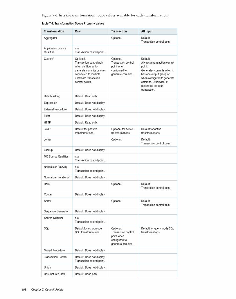
Figure 7-1 lists the transformation scope values available for each transformation:
Table 7-1. Transformation Scope Property Values
Transformation Row Transaction All Input
Aggregator Optional. Default. Transaction control point.
Application Source Qualifier
n/aTransaction control point.
Custom* Optional.Transaction control point when configured to generate commits or when connected to multiple upstream transaction control points.
Optional.Transaction control point when configured to generate commits.
Default. Always a transaction control point.Generates commits when it has one output group or when configured to generate commits. Otherwise, it generates an open transaction.
Data Masking Default. Read only.
Expression Default. Does not display.
External Procedure Default. Does not display.
Filter Default. Does not display.
HTTP Default. Read only.
Java* Default for passive transformations.
Optional for active transformations.
Default for active transformations.
Joiner Optional. Default. Transaction control point.
Lookup Default. Does not display.
MQ Source Qualifier n/aTransaction control point.
Normalizer (VSAM) n/aTransaction control point.
Normalizer (relational) Default. Does not display.
Rank Optional. Default. Transaction control point.
Router Default. Does not display.
Sorter Optional. Default. Transaction control point.
Sequence Generator Default. Does not display.
Source Qualifier n/aTransaction control point.
SQL Default for script mode SQL transformations.
Optional.Transaction control point when configured to generate commits.
Default for query mode SQL transformations.
Stored Procedure Default. Does not display.
Transaction Control Default. Does not display.Transaction control point.
Union Default. Does not display.
Unstructured Data Default. Read only.
108 Chapter 7: Commit Points

Understanding Transaction Control UnitsA transaction control unit is the group of targets connected to an active source that generates commits or an effective transaction generator. A transaction control unit is a subset of a target load order group and may contain multiple target connection groups.
When the Integration Service reaches the commit point for all targets in a transaction control unit, it issues commits sequentially for each target.
The following figure illustrates transaction control units with a Transaction Control transformation:
Note that T5_ora1 uses the same connection name as T1_ora1 and T2_ora1. Because T5_ora1 is connected to a separate Transaction Control transformation, it is in a separate transaction control unit and target connection group. If you connect T5_ora1 to tc_TransactionControlUnit1, it will be in the same transaction control unit as all targets, and in the same target connection group as T1_ora1 and T2_ora1.
Rules and GuidelinesConsider the following rules and guidelines when you work with transaction control:
♦ Transformations with Transaction transformation scope must receive data from a single transaction control point.
Update Strategy Default. Does not display.
XML Generator Optional.Transaction when the flush on commit is set to create a new document.
Default. Does not display.
XML Parser Default. Does not display.
XML Source Qualifier n/aTransaction control point.
*For more information about how the Transformation Scope property affects Custom or Java transformations, see “Custom Transformation” or “Java Transformation” in the PowerCenter Transformation Guide.
Table 7-1. Transformation Scope Property Values
Transformation Row Transaction All Input
Target Connection Group 1
Target Connection Group 2
Target Connection Group 3
Target Connection Group 4
Transaction Control Unit 1
Transaction Control Unit 2
Target Load Order Group
Understanding Transaction Control 109
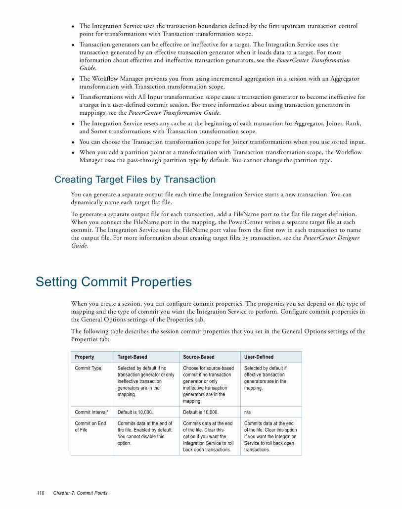
♦ The Integration Service uses the transaction boundaries defined by the first upstream transaction control point for transformations with Transaction transformation scope.
♦ Transaction generators can be effective or ineffective for a target. The Integration Service uses the transaction generated by an effective transaction generator when it loads data to a target. For more information about effective and ineffective transaction generators, see the PowerCenter Transformation Guide.
♦ The Workflow Manager prevents you from using incremental aggregation in a session with an Aggregator transformation with Transaction transformation scope.
♦ Transformations with All Input transformation scope cause a transaction generator to become ineffective for a target in a user-defined commit session. For more information about using transaction generators in mappings, see the PowerCenter Transformation Guide.
♦ The Integration Service resets any cache at the beginning of each transaction for Aggregator, Joiner, Rank, and Sorter transformations with Transaction transformation scope.
♦ You can choose the Transaction transformation scope for Joiner transformations when you use sorted input.
♦ When you add a partition point at a transformation with Transaction transformation scope, the Workflow Manager uses the pass-through partition type by default. You cannot change the partition type.
Creating Target Files by TransactionYou can generate a separate output file each time the Integration Service starts a new transaction. You can dynamically name each target flat file.
To generate a separate output file for each transaction, add a FileName port to the flat file target definition. When you connect the FileName port in the mapping, the PowerCenter writes a separate target file at each commit. The Integration Service uses the FileName port value from the first row in each transaction to name the output file. For more information about creating target files by transaction, see the PowerCenter Designer Guide.
Setting Commit PropertiesWhen you create a session, you can configure commit properties. The properties you set depend on the type of mapping and the type of commit you want the Integration Service to perform. Configure commit properties in the General Options settings of the Properties tab.
The following table describes the session commit properties that you set in the General Options settings of the Properties tab:
Property Target-Based Source-Based User-Defined
Commit Type Selected by default if no transaction generator or only ineffective transaction generators are in the mapping.
Choose for source-based commit if no transaction generator or only ineffective transaction generators are in the mapping.
Selected by default if effective transaction generators are in the mapping.
Commit Interval* Default is 10,000. Default is 10,000. n/a
Commit on End of File
Commits data at the end of the file. Enabled by default. You cannot disable this option.
Commits data at the end of the file. Clear this option if you want the Integration Service to roll back open transactions.
Commits data at the end of the file. Clear this option if you want the Integration Service to roll back open transactions.
110 Chapter 7: Commit Points

Roll Back Transactions on Errors
If the Integration Service encounters a non-fatal error, you can choose to roll back the transaction at the next commit point.When the Integration Service encounters a transformation error, it rolls back the transaction if the error occurs after the effective transaction generator for the target.
If the Integration Service encounters a non-fatal error, you can choose to roll back the transaction at the next commit point.When the Integration Service encounters a transformation error, it rolls back the transaction if the error occurs after the effective transaction generator for the target.
If the Integration Service encounters a non-fatal error, you can choose to roll back the transaction at the next commit point.When the Integration Service encounters a transformation error, it rolls back the transaction if the error occurs after the effective transaction generator for the target.
* Tip: When you bulk load to Microsoft SQL Server or Oracle targets, define a large commit interval. Microsoft SQL Server and Oracle start a new bulk load transaction after each commit. Increasing the commit interval reduces the number of bulk load transactions and increases performance.
Property Target-Based Source-Based User-Defined
Setting Commit Properties 111

112 Chapter 7: Commit Points

C H A P T E R 8
Row Error Logging
This chapter includes the following topics:
♦ Overview, 113
♦ Understanding the Error Log Tables, 114
♦ Understanding the Error Log File, 119
♦ Configuring Error Log Options, 120
OverviewWhen you configure a session, you can log row errors in a central location. When a row error occurs, the Integration Service logs error information that lets you determine the cause and source of the error. The Integration Service logs information such as source name, row ID, current row data, transformation, timestamp, error code, error message, repository name, folder name, session name, and mapping information.
You can log row errors into relational tables or flat files. When you enable error logging, the Integration Service creates the error tables or an error log file the first time it runs the session. Error logs are cumulative. If the error logs exist, the Integration Service appends error data to the existing error logs.
You can log source row data. Source row data includes row data, source row ID, and source row type from the source qualifier where an error occurs. The Integration Service cannot identify the row in the source qualifier that contains an error if the error occurs after a non pass-through partition point with more than one partition or one of the following active sources:
♦ Aggregator
♦ Custom, configured as an active transformation
♦ Joiner
♦ Normalizer (pipeline)
♦ Rank
♦ Sorter
By default, the Integration Service logs transformation errors in the session log and reject rows in the reject file. When you enable error logging, the Integration Service does not generate a reject file or write dropped rows to the session log. Without a reject file, the Integration Service does not log Transaction Control transformation rollback or commit errors. If you want to write rows to the session log in addition to the row error log, you can enable verbose data tracing.
Note: When you log row errors, session performance may decrease because the Integration Service processes one row at a time instead of a block of rows at once.
113

Error Log Code PagesThe Integration Service writes data to the error log file differently depending on the Integration Service process operating system:
♦ UNIX. The Integration Service writes data to the error log file using the Integration Service process code page. However, you can configure the Integration Service to write to the error log file using UTF-8 by enabling the LogsInUTF8 Integration Service property.
♦ Windows. The Integration Service writes all characters in the error log file using the UTF-8 encoding format.
The code page for the relational database where the error tables exist must be a subset of the target code page. If the error log table code page is not a subset of the target code page, the Integration Service might write inconsistent data in the error log tables.
Understanding the Error Log TablesWhen you choose relational database error logging, the Integration Service creates the following error tables the first time you run a session:
♦ PMERR_DATA. Stores data and metadata about a transformation row error and its corresponding source row.
♦ PMERR_MSG. Stores metadata about an error and the error message.
♦ PMERR_SESS. Stores metadata about the session.
♦ PMERR_TRANS. Stores metadata about the source and transformation ports, such as name and datatype, when a transformation error occurs.
You specify the database connection to the database where the Integration Service creates these tables. If the error tables exist for a session, the Integration Service appends row errors to these tables.
Relational database error logging lets you collect row errors from multiple sessions in one set of error tables. To do this, you specify the same error log table name prefix for all sessions. You can issue select statements on the generated error tables to retrieve error data for a particular session.
You can specify a prefix for the error tables. The error table names can have up to eleven characters. Do not specify a prefix that exceeds 19 characters when naming Oracle, Sybase, or Teradata error log tables, as these databases have a maximum length of 30 characters for table names. You can use a parameter or variable for the table name prefix. Use any parameter or variable type that you can define in the parameter file. For example, you can use a session parameter, $ParamMyErrPrefix, as the error log table name prefix, and set $ParamMyErrPrefix to the table prefix in a parameter file.
The Integration Service creates the error tables without specifying primary and foreign keys. However, you can specify key columns.
PMERR_DATAWhen the Integration Service encounters a row error, it inserts an entry into the PMERR_DATA table. This table stores data and metadata about a transformation row error and its corresponding source row.
The following table describes the structure of the PMERR_DATA table:
Column Name Datatype Description
REPOSITORY_GID Varchar Unique identifier for the repository.
WORKFLOW_RUN_ID Integer Unique identifier for the workflow.
114 Chapter 8: Row Error Logging

WORKLET_RUN_ID Integer Unique identifier for the worklet. If a session is not part of a worklet, this value is “0”.
SESS_INST_ID Integer Unique identifier for the session.
TRANS_MAPPLET_INST Varchar Name of the mapplet where an error occurred.
TRANS_NAME Varchar Name of the transformation where an error occurred.
TRANS_GROUP Varchar Name of the input group or output group where an error occurred. Defaults to either “input” or “output” if the transformation does not have a group.
TRANS_PART_INDEX Integer Specifies the partition number of the transformation where an error occurred.
TRANS_ROW_ID Integer Specifies the row ID generated by the last active source.
TRANS_ROW_DATA Long Varchar Delimited string containing all column data, including the column indicator. Column indicators are:D - validN - nullT - truncatedB - binaryU - data unavailableThe fixed delimiter between column data and column indicator is colon ( : ). The delimiter between the columns is pipe ( | ). You can override the column delimiter in the error handling settings.
The Integration Service converts all column data to text string in the error table. For binary data, the Integration Service uses only the column indicator.
This value can span multiple rows. When the data exceeds 2000 bytes, the Integration Service creates a new row. The line number for each row error entry is stored in the LINE_NO column.
SOURCE_ROW_ID Integer Value that the source qualifier assigns to each row it reads. If the Integration Service cannot identify the row, the value is -1.
SOURCE_ROW_TYPE Integer Row indicator that tells whether the row was marked for insert, update, delete, or reject. 0 - Insert1 - Update2 - Delete3 - Reject
Column Name Datatype Description
Understanding the Error Log Tables 115

PMERR_MSGWhen the Integration Service encounters a row error, it inserts an entry into the PMERR_MSG table. This table stores metadata about the error and the error message.
The following table describes the structure of the PMERR_MSG table:
SOURCE_ROW_DATA Long Varchar Delimited string containing all column data, including the column indicator. Column indicators are:D - validO - overflowN - nullT - truncatedB - binaryU - data unavailableThe fixed delimiter between column data and column indicator is colon ( : ). The delimiter between the columns is pipe ( | ). You can override the column delimiter in the error handling settings.
The Integration Service converts all column data to text string in the error table or error file. For binary data, the Integration Service uses only the column indicator.
This value can span multiple rows. When the data exceeds 2000 bytes, the Integration Service creates a new row. The line number for each row error entry is stored in the LINE_NO column.
LINE_NO Integer Specifies the line number for each row error entry in SOURCE_ROW_DATA and TRANS_ROW_DATA that spans multiple rows.
Note: Use the column names in bold to join tables.
Column Name Datatype Description
REPOSITORY_GID Varchar Unique identifier for the repository.
WORKFLOW_RUN_ID Integer Unique identifier for the workflow.
WORKLET_RUN_ID Integer Unique identifier for the worklet. If a session is not part of a worklet, this value is “0”.
SESS_INST_ID Integer Unique identifier for the session.
MAPPLET_INST_NAME Varchar Mapplet to which the transformation belongs. If the transformation is not part of a mapplet, this value is n/a.
TRANS_NAME Varchar Name of the transformation where an error occurred.
TRANS_GROUP Varchar Name of the input group or output group where an error occurred. Defaults to either “input” or “output” if the transformation does not have a group.
TRANS_PART_INDEX Integer Specifies the partition number of the transformation where an error occurred.
TRANS_ROW_ID Integer Specifies the row ID generated by the last active source.
ERROR_SEQ_NUM Integer Counter for the number of errors per row in each transformation group. If a session has multiple partitions, the Integration Service maintains this counter for each partition. For example, if a transformation generates three errors in partition 1 and two errors in partition 2, ERROR_SEQ_NUM generates the values 1, 2, and 3 for partition 1, and values 1 and 2 for partition 2.
Column Name Datatype Description
116 Chapter 8: Row Error Logging

PMERR_SESSWhen you choose relational database error logging, the Integration Service inserts entries into the PMERR_SESS table. This table stores metadata about the session where an error occurred.
The following table describes the structure of the PMERR_SESS table:
ERROR_TIMESTAMP Date/Time Timestamp of the Integration Service when the error occurred.
ERROR_UTC_TIME Integer Coordinated Universal Time, called Greenwich Mean Time, of when an error occurred.
ERROR_CODE Integer Error code that the error generates.
ERROR_MSG Long Varchar Error message, which can span multiple rows. When the data exceeds 2000 bytes, the Integration Service creates a new row. The line number for each row error entry is stored in the LINE_NO column.
ERROR_TYPE Integer Type of error that occurred. The Integration Service uses the following values:1 - Reader error2 - Writer error3 - Transformation error
LINE_NO Integer Specifies the line number for each row error entry in ERROR_MSG that spans multiple rows.
Note: Use the column names in bold to join tables.
Column Name Datatype Description
REPOSITORY_GID Varchar Unique identifier for the repository.
WORKFLOW_RUN_ID Integer Unique identifier for the workflow.
WORKLET_RUN_ID Integer Unique identifier for the worklet. If a session is not part of a worklet, this value is “0”.
SESS_INST_ID Integer Unique identifier for the session.
SESS_START_TIME Date/Time Timestamp of the Integration Service when a session starts.
SESS_START_UTC_TIME Integer Coordinated Universal Time, called Greenwich Mean Time, of when the session starts.
REPOSITORY_NAME Varchar Repository name where sessions are stored.
FOLDER_NAME Varchar Specifies the folder where the mapping and session are located.
WORKFLOW_NAME Varchar Specifies the workflow that runs the session being logged.
TASK_INST_PATH Varchar Fully qualified session name that can span multiple rows. The Integration Service creates a new line for the session name. The Integration Service also creates a new line for each worklet in the qualified session name. For example, you have a session named WL1.WL2.S1. Each component of the name appears on a new line:WL1WL2S1The Integration Service writes the line number in the LINE_NO column.
MAPPING_NAME Varchar Specifies the mapping that the session uses.
Column Name Datatype Description
Understanding the Error Log Tables 117

PMERR_TRANSWhen the Integration Service encounters a transformation error, it inserts an entry into the PMERR_TRANS table. This table stores metadata, such as the name and datatype of the source and transformation ports.
The following table describes the structure of the PMERR_TRANS table:
LINE_NO Integer Specifies the line number for each row error entry in TASK_INST_PATH that spans multiple rows.
Note: Use the column names in bold to join tables.
Column Name Datatype Description
REPOSITORY_GID Varchar Unique identifier for the repository.
WORKFLOW_RUN_ID Integer Unique identifier for the workflow.
WORKLET_RUN_ID Integer Unique identifier for the worklet. If a session is not part of a worklet, this value is “0”.
SESS_INST_ID Integer Unique identifier for the session.
TRANS_MAPPLET_INST Varchar Specifies the instance of a mapplet.
TRANS_NAME Varchar Name of the transformation where an error occurred.
TRANS_GROUP Varchar Name of the input group or output group where an error occurred. Defaults to either “input” or “output” if the transformation does not have a group.
TRANS_ATTR Varchar Lists the port names and datatypes of the input or output group where the error occurred. Port name and datatype pairs are separated by commas, for example: portname1:datatype, portname2:datatype.
This value can span multiple rows. When the data exceeds 2000 bytes, the Integration Service creates a new row for the transformation attributes and writes the line number in the LINE_NO column.
SOURCE_MAPPLET_INST
Varchar Name of the mapplet in which the source resides.
SOURCE_NAME Varchar Name of the source qualifier. n/a appears when a row error occurs downstream of an active source that is not a source qualifier or a non pass-through partition point with more than one partition.
SOURCE_ATTR Varchar Lists the connected field(s) in the source qualifier where an error occurred. When an error occurs in multiple fields, each field name is entered on a new line. Writes the line number in the LINE_NO column.
LINE_NO Integer Specifies the line number for each row error entry in TRANS_ATTR and SOURCE_ATTR that spans multiple rows.
Note: Use the column names in bold to join tables.
Column Name Datatype Description
118 Chapter 8: Row Error Logging
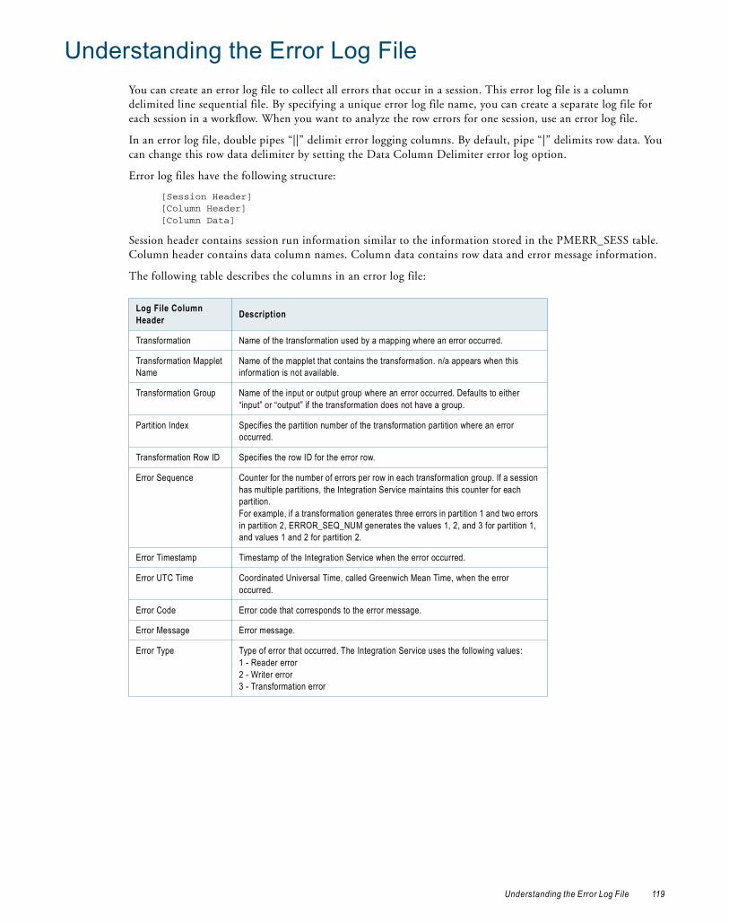
Understanding the Error Log FileYou can create an error log file to collect all errors that occur in a session. This error log file is a column delimited line sequential file. By specifying a unique error log file name, you can create a separate log file for each session in a workflow. When you want to analyze the row errors for one session, use an error log file.
In an error log file, double pipes “||” delimit error logging columns. By default, pipe “|” delimits row data. You can change this row data delimiter by setting the Data Column Delimiter error log option.
Error log files have the following structure:
[Session Header][Column Header][Column Data]
Session header contains session run information similar to the information stored in the PMERR_SESS table. Column header contains data column names. Column data contains row data and error message information.
The following table describes the columns in an error log file:
Log File Column Header Description
Transformation Name of the transformation used by a mapping where an error occurred.
Transformation Mapplet Name
Name of the mapplet that contains the transformation. n/a appears when this information is not available.
Transformation Group Name of the input or output group where an error occurred. Defaults to either “input” or “output” if the transformation does not have a group.
Partition Index Specifies the partition number of the transformation partition where an error occurred.
Transformation Row ID Specifies the row ID for the error row.
Error Sequence Counter for the number of errors per row in each transformation group. If a session has multiple partitions, the Integration Service maintains this counter for each partition. For example, if a transformation generates three errors in partition 1 and two errors in partition 2, ERROR_SEQ_NUM generates the values 1, 2, and 3 for partition 1, and values 1 and 2 for partition 2.
Error Timestamp Timestamp of the Integration Service when the error occurred.
Error UTC Time Coordinated Universal Time, called Greenwich Mean Time, when the error occurred.
Error Code Error code that corresponds to the error message.
Error Message Error message.
Error Type Type of error that occurred. The Integration Service uses the following values:1 - Reader error2 - Writer error3 - Transformation error
Understanding the Error Log File 119
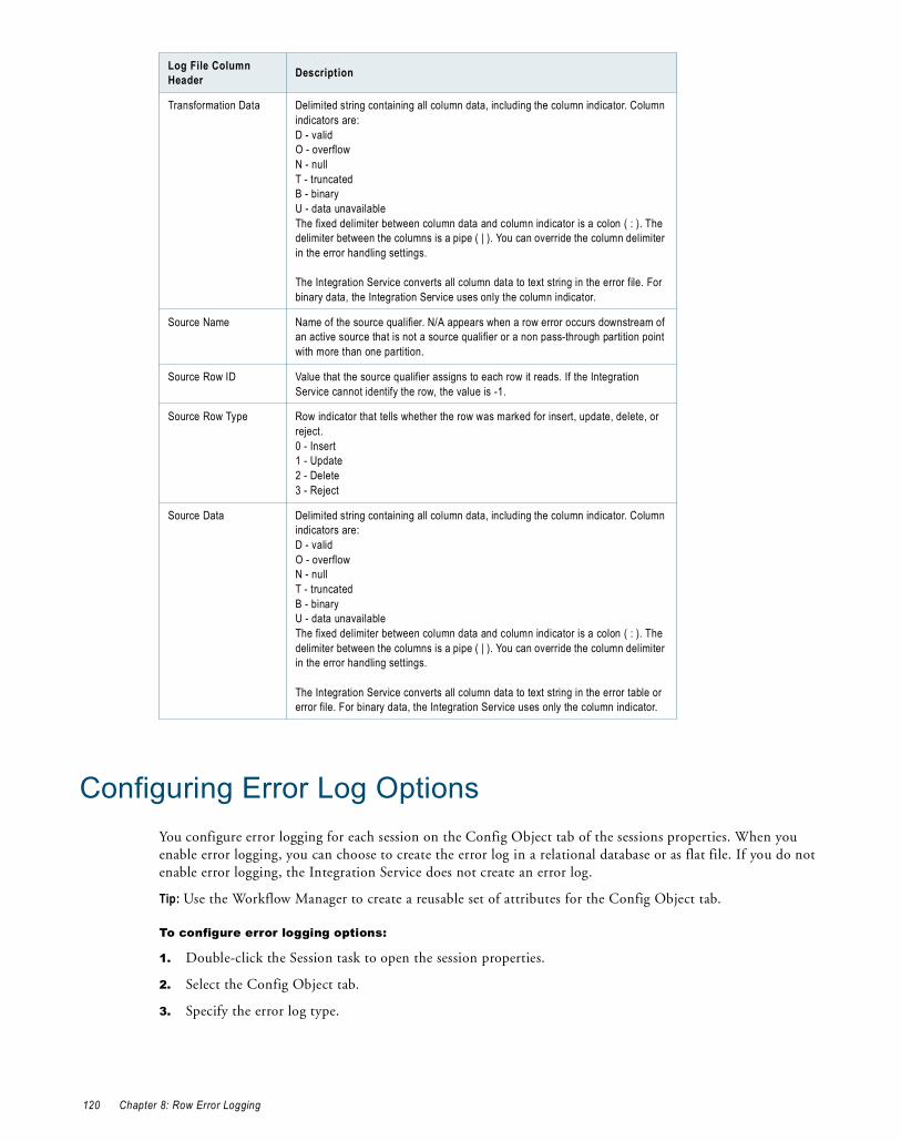
Configuring Error Log OptionsYou configure error logging for each session on the Config Object tab of the sessions properties. When you enable error logging, you can choose to create the error log in a relational database or as flat file. If you do not enable error logging, the Integration Service does not create an error log.
Tip: Use the Workflow Manager to create a reusable set of attributes for the Config Object tab.
To configure error logging options:
1. Double-click the Session task to open the session properties.
2. Select the Config Object tab.
3. Specify the error log type.
Transformation Data Delimited string containing all column data, including the column indicator. Column indicators are:D - validO - overflowN - nullT - truncatedB - binaryU - data unavailableThe fixed delimiter between column data and column indicator is a colon ( : ). The delimiter between the columns is a pipe ( | ). You can override the column delimiter in the error handling settings.
The Integration Service converts all column data to text string in the error file. For binary data, the Integration Service uses only the column indicator.
Source Name Name of the source qualifier. N/A appears when a row error occurs downstream of an active source that is not a source qualifier or a non pass-through partition point with more than one partition.
Source Row ID Value that the source qualifier assigns to each row it reads. If the Integration Service cannot identify the row, the value is -1.
Source Row Type Row indicator that tells whether the row was marked for insert, update, delete, or reject. 0 - Insert1 - Update2 - Delete3 - Reject
Source Data Delimited string containing all column data, including the column indicator. Column indicators are:D - validO - overflowN - nullT - truncatedB - binaryU - data unavailableThe fixed delimiter between column data and column indicator is a colon ( : ). The delimiter between the columns is a pipe ( | ). You can override the column delimiter in the error handling settings.
The Integration Service converts all column data to text string in the error table or error file. For binary data, the Integration Service uses only the column indicator.
Log File Column Header Description
120 Chapter 8: Row Error Logging

The following table describes the error logging settings of the Config Object tab:
4. Click OK.
Error Log Options Description
Error Log Type Specifies the type of error log to create. You can specify relational database, flat file, or none. By default, the Integration Service does not create an error log.
Error Log DB Connection
Specifies the database connection for a relational log. This option is required when you enable relational database logging.
Error Log Table Name Prefix
Specifies the table name prefix for relational logs. The Integration Service appends 11 characters to the prefix name. Oracle and Sybase have a 30 character limit for table names. If a table name exceeds 30 characters, the session fails.You can use a parameter or variable for the error log table name prefix. Use any parameter or variable type that you can define in the parameter file.
Error Log File Directory
Specifies the directory where errors are logged. By default, the error log file directory is $PMBadFilesDir\. This option is required when you enable flat file logging.
Error Log File Name Specifies error log file name. The character limit for the error log file name is 255. By default, the error log file name is PMError.log. This option is required when you enable flat file logging.
Log Row Data Specifies whether or not to log transformation row data. When you enable error logging, the Integration Service logs transformation row data by default. If you disable this property, n/a or -1 appears in transformation row data fields.
Log Source Row Data If you choose not to log source row data, or if source row data is unavailable, the Integration Service writes an indicator such as n/a or -1, depending on the column datatype.If you do not need to capture source row data, consider disabling this option to increase Integration Service performance.
Data Column Delimiter
Delimiter for string type source row data and transformation group row data. By default, the Integration Service uses a pipe ( | ) delimiter. Verify that you do not use the same delimiter for the row data as the error logging columns. If you use the same delimiter, you may find it difficult to read the error log file.
Configuring Error Log Options 121

122 Chapter 8: Row Error Logging

C H A P T E R 9
Workflow Recovery
This chapter includes the following topics:
♦ Overview, 123
♦ State of Operation, 124
♦ Recovery Options, 127
♦ Suspending the Workflow, 128
♦ Configuring Workflow Recovery, 129
♦ Configuring Task Recovery, 129
♦ Resuming Sessions, 132
♦ Working with Repeatable Data, 133
♦ Steps to Recover Workflows and Tasks, 136
♦ Rules and Guidelines for Session Recovery, 138
OverviewWorkflow recovery allows you to continue processing the workflow and workflow tasks from the point of interruption. You can recover a workflow if the Integration Service can access the workflow state of operation. The workflow state of operation includes the status of tasks in the workflow and workflow variable values. The Integration Service stores the state in memory or on disk, based on how you configure the workflow:
♦ Enable recovery. When you enable a workflow for recovery, the Integration Service saves the workflow state of operation in a shared location. You can recover the workflow if it terminates, stops, or aborts. The workflow does not have to be running.
♦ Suspend. When you configure a workflow to suspend on error, the Integration Service stores the workflow state of operation in memory. You can recover the suspended workflow if a task fails. You can fix the task error and recover the workflow.
The Integration Service recovers tasks in the workflow based on the recovery strategy of the task. By default, the recovery strategy for Session and Command tasks is to fail the task and continue running the workflow. You can configure the recovery strategy for Session and Command tasks. The strategy for all other tasks is to restart the task.
When you have high availability, PowerCenter recovers a workflow automatically if a service process that is running the workflow fails over to a different node. You can configure a running workflow to recover a task automatically when the task terminates. PowerCenter also recovers a session and workflow after a database connection interruption.
123

When the Integration Service runs in safe mode, it stores the state of operation for workflows configured for recovery. If the workflow fails the Integration Service fails over to a backup node, the Integration Service does not automatically recover the workflow. You can manually recover the workflow if you have the appropriate privileges on the Integration Service.
State of OperationWhen you recover a workflow or session, the Integration Service restores the workflow or session state of operation to determine where to begin recovery processing. The Integration Service stores the workflow state of operation in memory or on disk based on the way you configure the workflow. The Integration Service stores the session state of operation based on the way you configure the session.
Workflow State of Operation The Integration Service stores the workflow state of operation when you enable the workflow for recovery or for suspension. When the workflow is suspended, the state of operation is in memory.
When you enable a workflow for recovery, the Integration Service stores the workflow state of operation in the shared location, $PMStorageDir. The Integration Service can restore the state of operation to recover a stopped, aborted, or terminated workflow. When it performs recovery, it restores the state of operation to recover the workflow from the point of interruption. When the workflow completes, the Integration Service removes the workflow state of operation from the shared folder.
The workflow state of operation includes the following information:
♦ Active service requests
♦ Completed and running task status
♦ Workflow variable values
When you run concurrent workflows, the Integration Service appends the instance name or the workflow run ID to the workflow recovery storage file in $PMStorageDir.
When you enable a workflow for recovery the Integration Service does not store the session state of operation by default. You can configure the session recovery strategy to save the session state of operation.
Session State of OperationWhen you configure the session recovery strategy to resume from the last checkpoint, the Integration Service stores the session state of operation in the shared location, $PMStorageDir. The Integration Service also saves relational target recovery information in target database tables. When the Integration Service performs recovery, it restores the state of operation to recover the session from the point of interruption. It uses the target recovery data to determine how to recover the target tables.
You can configure the session to save the session state of operation even if you do not save the workflow state of operation. You can recover the session, or you can recover the workflow from the session.
The session state of operation includes the following information:
♦ Source. If the output from a source is not deterministic and repeatable, the Integration Service saves the result from the SQL query to a shared storage file in $PMStorageDir.
♦ Transformation. The Integration Service creates checkpoints in $PMStorageDir to determine where to start processing the pipeline when it runs a recovery session.
When you run a session with an incremental Aggregator transformation, the Integration Service creates a backup of the Aggregator cache files in $PMCacheDir at the beginning of a session run. The Integration Service promotes the backup cache to the initial cache at the beginning of a session recovery run.
124 Chapter 9: Workflow Recovery

♦ Relational target recovery data. The Integration Service writes recovery information to recovery tables in the target database to determine the last row committed to the target when the session was interrupted.
RELATED TOPICS:♦ “Working with Repeatable Data” on page 133
Target Recovery TablesWhen the Integration Service runs a session that has a resume recovery strategy, it writes to recovery tables on the target database system. When the Integration Service recovers the session, it uses information in the recovery tables to determine where to begin loading data to target tables.
If you want the Integration Service to create the recovery tables, grant table creation privilege to the database user name configured in the target database connection. If you do not want the Integration Service to create the recovery tables, create the recovery tables manually.
The Integration Service creates the following recovery tables in the target database:
♦ PM_RECOVERY. Contains target load information for the session run. The Integration Service removes the information from this table after each successful session and initializes the information at the beginning of subsequent sessions.
♦ PM_TGT_RUN_ID. Contains information the Integration Service uses to identify each target on the database. The information remains in the table between session runs. If you manually create this table, you must create a row and enter a value other than zero for LAST_TGT_RUN_ID to ensure that the session recovers successfully.
♦ PM_REC_STATE. Contains information the Integration Service uses to determine if it needs to write messages to the target table during recovery for a real-time session.
If you edit or drop the recovery tables before you recover a session, the Integration Service cannot recover the session. If you disable recovery, the Integration Service does not remove the recovery tables from the target database. You must manually remove the recovery tables.
The following table describes the format of PM_RECOVERY:
The following table describes the format of PM_TGT_RUN_ID:
Column Name Datatype
REP_GID VARCHAR(240)
WFLOW_ID INTEGER
WFLOW_RUN_ID INTEGER
WFLOW_RUN_INS_NAME VARCHAR(240)
SUBJ_ID INTEGER
TASK_INST_ID INTEGER
TGT_INST_ID INTEGER
PARTITION_ID INTEGER
TGT_RUN_ID INTEGER
RECOVERY_VER INTEGER
CHECK_POINT INTEGER
ROW_COUNT INTEGER
Column Name Datatype
LAST_TGT_RUN_ID INTEGER
State of Operation 125

The following table describes the format of PM_REC_STATE:
Oracle uses the NUMBER datatype instead of the INTEGER datatype.
Note: When concurrent recovery sessions write to the same target database, the Integration Service may encounter a deadlock on PM_RECOVERY. To retry writing to PM_RECOVERY on deadlock, you can configure the Session Retry on Deadlock option to retry the deadlock for the session.
RELATED TOPICS:♦ “PM_REC_STATE Table” on page 91
Creating Target Recovery TablesYou can manually create the target recovery tables. Informatica provides SQL scripts in the following directory:
<PowerCenter installation_dir>\server\bin\RecoverySQL
Run one of the following scripts to create the recovery tables in the target database:
Column Name Datatype
OWNER_TYPE_ID INTEGER
REP_GID VARCHAR(240)
FOLDER_ID INTEGER
WFLOW_ID INTEGER
WFLOW_RUN_INS_NAME VARCHAR(240)
WLET_ID INTEGER
TASK_INST_ID INTEGER
WID_INST_ID INTEGER
GROUP_ID INTEGER
PART_ID INTEGER
PLUGIN_ID INTEGER
APPL_ID VARCHAR(38)
SEQ_NUM INTEGER
VERSION INTEGER
CHKP_NUM INTEGER
STATE_DATA VARCHAR(1024)
Script Database
create_schema_db2.sql IBM DB2
create_schema_inf.sql Informix
create_schema_ora.sql Oracle
create_schema_sql.sql Microsoft SQL Server
create_schema_syb.sql Sybase
create_schema_ter.sql Teradata
126 Chapter 9: Workflow Recovery
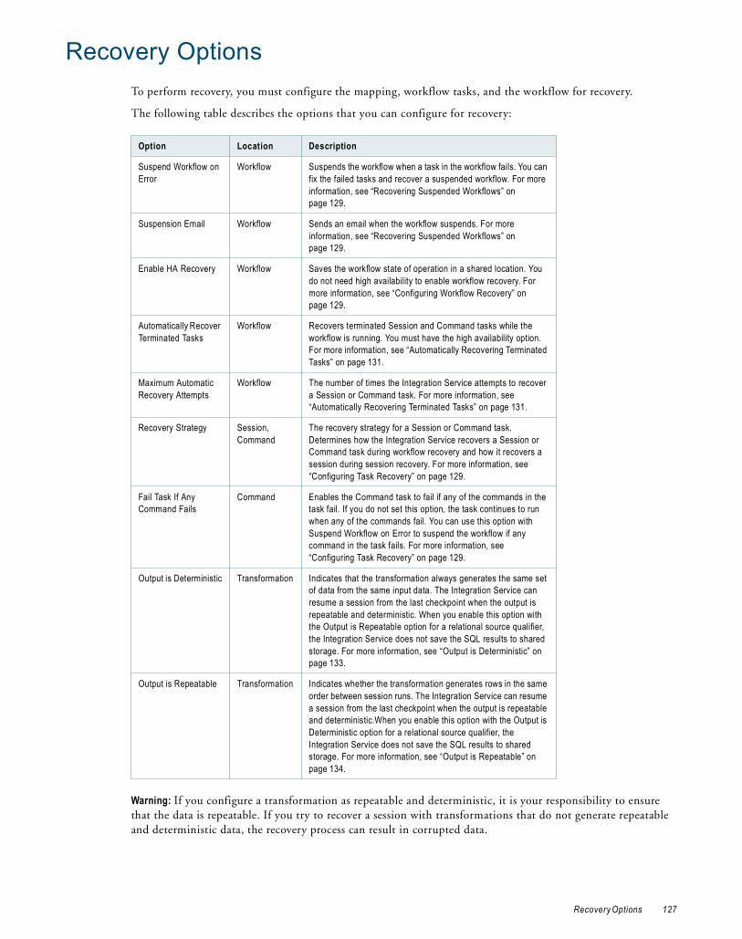
Recovery OptionsTo perform recovery, you must configure the mapping, workflow tasks, and the workflow for recovery.
The following table describes the options that you can configure for recovery:
Warning: If you configure a transformation as repeatable and deterministic, it is your responsibility to ensure that the data is repeatable. If you try to recover a session with transformations that do not generate repeatable and deterministic data, the recovery process can result in corrupted data.
Option Location Description
Suspend Workflow on Error
Workflow Suspends the workflow when a task in the workflow fails. You can fix the failed tasks and recover a suspended workflow. For more information, see “Recovering Suspended Workflows” on page 129.
Suspension Email Workflow Sends an email when the workflow suspends. For more information, see “Recovering Suspended Workflows” on page 129.
Enable HA Recovery Workflow Saves the workflow state of operation in a shared location. You do not need high availability to enable workflow recovery. For more information, see “Configuring Workflow Recovery” on page 129.
Automatically Recover Terminated Tasks
Workflow Recovers terminated Session and Command tasks while the workflow is running. You must have the high availability option. For more information, see “Automatically Recovering Terminated Tasks” on page 131.
Maximum Automatic Recovery Attempts
Workflow The number of times the Integration Service attempts to recover a Session or Command task. For more information, see “Automatically Recovering Terminated Tasks” on page 131.
Recovery Strategy Session,Command
The recovery strategy for a Session or Command task. Determines how the Integration Service recovers a Session or Command task during workflow recovery and how it recovers a session during session recovery. For more information, see “Configuring Task Recovery” on page 129.
Fail Task If Any Command Fails
Command Enables the Command task to fail if any of the commands in the task fail. If you do not set this option, the task continues to run when any of the commands fail. You can use this option with Suspend Workflow on Error to suspend the workflow if any command in the task fails. For more information, see “Configuring Task Recovery” on page 129.
Output is Deterministic Transformation Indicates that the transformation always generates the same set of data from the same input data. The Integration Service can resume a session from the last checkpoint when the output is repeatable and deterministic. When you enable this option with the Output is Repeatable option for a relational source qualifier, the Integration Service does not save the SQL results to shared storage. For more information, see “Output is Deterministic” on page 133.
Output is Repeatable Transformation Indicates whether the transformation generates rows in the same order between session runs. The Integration Service can resume a session from the last checkpoint when the output is repeatable and deterministic.When you enable this option with the Output is Deterministic option for a relational source qualifier, the Integration Service does not save the SQL results to shared storage. For more information, see “Output is Repeatable” on page 134.
Recovery Options 127

Suspending the WorkflowWhen a task in the workflow fails, you might want to suspend the workflow, fix the error, and recover the workflow. The Integration Service suspends the workflow when you enable the Suspend on Error option in the workflow properties. Optionally, you can set a suspension email so the Integration Service sends an email when it suspends a workflow.
When you enable the workflow to suspend on error, the Integration Service suspends the workflow when one of the following tasks fail:
♦ Session
♦ Command
♦ Worklet
When a task fails in the workflow, the Integration Service stops running tasks in the path. The Integration Service does not evaluate the output link of the failed task. If no other task is running in the workflow, the Workflow Monitor displays the status of the workflow as “Suspended.”
If you have the high availability option, the Integration Service suspends the workflow depending on how automatic task recovery is set. If you configure the workflow to suspend on error and do not enable automatic task recovery, the workflow suspends when a task fails. If you enable automatic task recovery, the Integration Service first attempts to restart the task up to the specified recovery limit, and then suspends the workflow if it cannot restart the failed task.
If one or more tasks are still running in the workflow when a task fails, the Integration Service stops running the failed task and continues running tasks in other paths. The Workflow Monitor displays the status of the workflow as “Suspending.”
When the status of the workflow is “Suspended” or “Suspending,” you can fix the error, such as a target database error, and recover the workflow in the Workflow Monitor. When you recover a workflow, the Integration Service restarts the failed tasks and continues evaluating the rest of the tasks in the workflow. The Integration Service does not run any task that already completed successfully.
Note: Editing a suspended workflow or tasks inside a suspended workflow can cause repository inconsistencies.
To suspend a workflow:
1. In the Workflow Designer, open the workflow.
2. Click Workflows > Edit.
3. In the General tab, enable Suspend on Error.
4. Click OK.
Configuring Suspension EmailYou can configure the workflow so that the Integration Service sends an email when it suspends a workflow. Select an existing reusable email task for the suspension email. When a task fails, the Integration Service starts suspending the workflow and sends the suspension email. If another task fails while the Integration Service is suspending the workflow, you do not receive the suspension email again.
The Integration Service sends a suspension email if another task fails after you resume the workflow.
128 Chapter 9: Workflow Recovery

Configuring Workflow RecoveryTo configure a workflow for recovery, you must enable the workflow for recovery or configure the workflow to suspend on task error. When the workflow is configured for recovery, you can recover it if it stops, aborts, terminates, or suspends.
The following table describes each recoverable workflow status:
For more information about workflow status, see the PowerCenter Workflow Basics Guide.
Recovering Stopped, Aborted, and Terminated WorkflowsWhen you enable a workflow for recovery, the Integration Service saves the workflow state of operation to a file during the workflow run. You can recover a stopped, terminated, or aborted workflow. Enable recovery on the Properties tab of the workflow.
Recovering Suspended WorkflowsYou can configure a workflow to suspend if a task in the workflow fails. By default, a workflow continues to run when a task fails. You can suspend the workflow at task failure, fix the task that failed, and recover the workflow. When you suspend a workflow, the workflow state of operation stays in memory. You can fix the error that caused the task to fail and recover the workflow from the point of interruption. If the task fails again, the Integration Service suspends the workflow again. You can recover a suspended workflow, but you cannot restart it. Configure a workflow to suspend on the General tab of the workflow properties.
You can also configure the workflow to send an email when a task suspends.
Configuring Task RecoveryWhen you recover a workflow, the Integration Service recovers the tasks based on the recovery strategy for each task. Depending on the task, the recovery strategy can be fail task and continue workflow, resume from the last checkpoint, or restart task.
Status Description
Aborted You abort the workflow in the Workflow Monitor or through pmcmd. You can also choose to abort all running workflows when you disable the service process in the Administration Console. You can recover an aborted workflow if you enable the workflow for recovery. You can recover an aborted workflow in the Workflow Monitor or by using pmcmd.
Stopped You stop the workflow in the Workflow Monitor or through pmcmd. You can also choose to stop all running workflows when you disable the service or service process in the Administration Console. You can recover a stopped workflow if you enable the workflow for recovery. You can recover a stopped workflow in the Workflow Monitor or by using pmcmd.
Suspended A task fails and the workflow is configured to suspend on a task error. If multiple tasks are running, the Integration Service suspends the workflow when all running tasks either succeed or fail. You can fix the errors that caused the task or tasks to fail before you run recovery. By default, a workflow continues after a task fails. To suspend the workflow when a task fails, configure the workflow to suspend on task error.
Terminated The service process running the workflow shuts down unexpectedly. Tasks terminate on all nodes running the workflow. A workflow can terminate when a task in the workflow terminates and you do not have the high availability option. You can recover a terminated workflow if you enable the workflow for recovery. When you have high availability, the service process fails over to another node and workflow recovery starts.
Note: A failed workflow is a workflow that completes with failure. You cannot recover a failed workflow.
Configuring Workflow Recovery 129
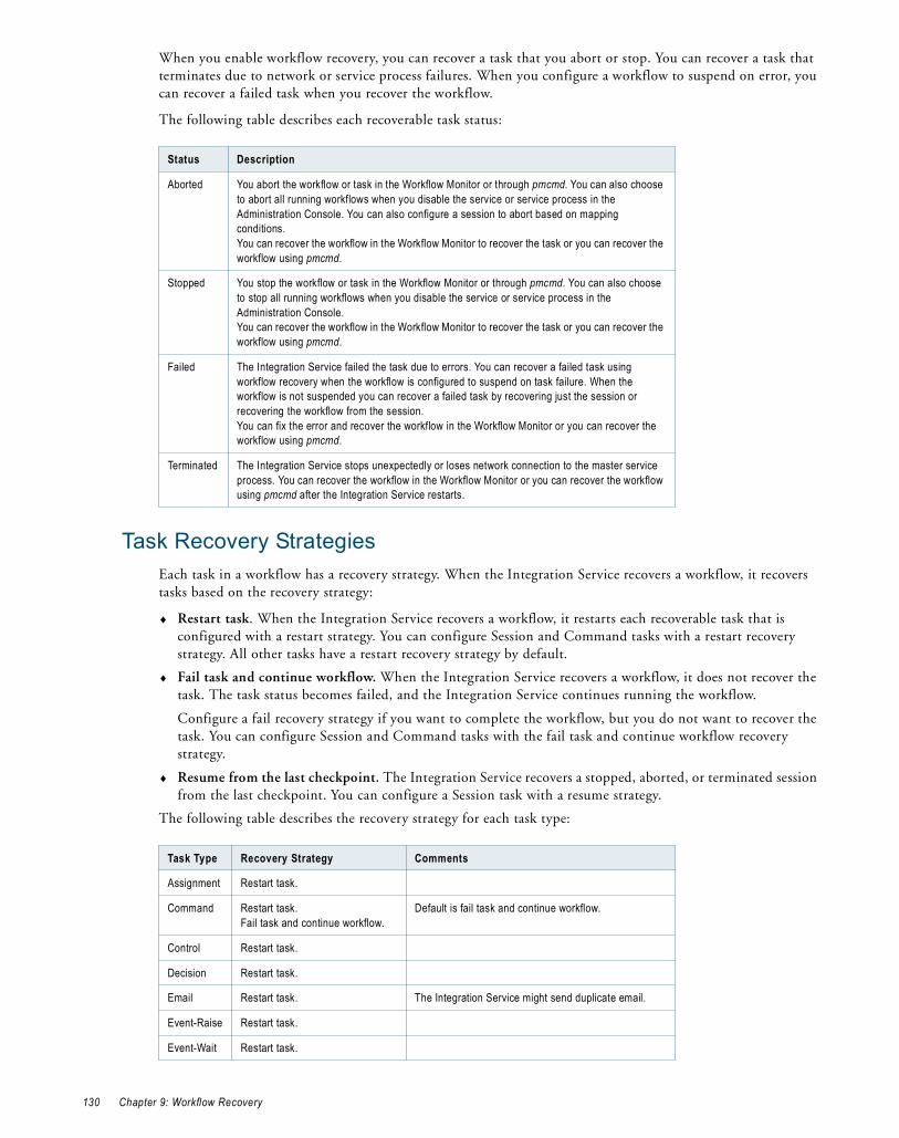
When you enable workflow recovery, you can recover a task that you abort or stop. You can recover a task that terminates due to network or service process failures. When you configure a workflow to suspend on error, you can recover a failed task when you recover the workflow.
The following table describes each recoverable task status:
Task Recovery StrategiesEach task in a workflow has a recovery strategy. When the Integration Service recovers a workflow, it recovers tasks based on the recovery strategy:
♦ Restart task. When the Integration Service recovers a workflow, it restarts each recoverable task that is configured with a restart strategy. You can configure Session and Command tasks with a restart recovery strategy. All other tasks have a restart recovery strategy by default.
♦ Fail task and continue workflow. When the Integration Service recovers a workflow, it does not recover the task. The task status becomes failed, and the Integration Service continues running the workflow.
Configure a fail recovery strategy if you want to complete the workflow, but you do not want to recover the task. You can configure Session and Command tasks with the fail task and continue workflow recovery strategy.
♦ Resume from the last checkpoint. The Integration Service recovers a stopped, aborted, or terminated session from the last checkpoint. You can configure a Session task with a resume strategy.
The following table describes the recovery strategy for each task type:
Status Description
Aborted You abort the workflow or task in the Workflow Monitor or through pmcmd. You can also choose to abort all running workflows when you disable the service or service process in the Administration Console. You can also configure a session to abort based on mapping conditions.You can recover the workflow in the Workflow Monitor to recover the task or you can recover the workflow using pmcmd.
Stopped You stop the workflow or task in the Workflow Monitor or through pmcmd. You can also choose to stop all running workflows when you disable the service or service process in the Administration Console.You can recover the workflow in the Workflow Monitor to recover the task or you can recover the workflow using pmcmd.
Failed The Integration Service failed the task due to errors. You can recover a failed task using workflow recovery when the workflow is configured to suspend on task failure. When the workflow is not suspended you can recover a failed task by recovering just the session or recovering the workflow from the session.You can fix the error and recover the workflow in the Workflow Monitor or you can recover the workflow using pmcmd.
Terminated The Integration Service stops unexpectedly or loses network connection to the master service process. You can recover the workflow in the Workflow Monitor or you can recover the workflow using pmcmd after the Integration Service restarts.
Task Type Recovery Strategy Comments
Assignment Restart task.
Command Restart task.Fail task and continue workflow.
Default is fail task and continue workflow.
Control Restart task.
Decision Restart task.
Email Restart task. The Integration Service might send duplicate email.
Event-Raise Restart task.
Event-Wait Restart task.
130 Chapter 9: Workflow Recovery

RELATED TOPICS:♦ “Configuring Task Recovery” on page 129
♦ “Session Task Strategies” on page 131
♦ “Resuming Sessions” on page 132
Command Task StrategiesWhen you configure a Command task, you can choose a recovery strategy to restart or fail:
♦ Fail task and continue workflow. If you want to suspend the workflow on Command task error, you must configure the task with a fail strategy. If the Command task has more than one command, and you configure a fail strategy, you need to configure the task to fail if any command fails.
♦ Restart task. When the Integration Service recovers a workflow, it restarts a Command task that is configured with a restart strategy.
Configure the recovery strategy on the Properties page of the Command task.
Session Task StrategiesWhen you configure a session for recovery, you can recover the session when you recover a workflow, or you can recover the session without running the rest of the workflow.
When you configure a session, you can choose a recovery strategy of fail, restart, or resume:
♦ Resume from the last checkpoint. The Integration Service saves the session state of operation and maintains target recovery tables. If the session aborts, stops, or terminates, the Integration Service uses the saved recovery information to resume the session from the point of interruption.
You cannot configure a session with a resume strategy if it uses mapping variables.
♦ Restart task. The Integration Service runs the session again when it recovers the workflow. When you recover with restart task, you might need to remove the partially loaded data in the target or design a mapping to skip the duplicate rows.
♦ Fail task and continue workflow. When the Integration Service recovers a workflow, it does not recover the session. The session status becomes failed, and the Integration Service continues running the workflow.
Configure the recovery strategy on the Properties page of the Session task.
Automatically Recovering Terminated TasksWhen you have the high availability option, you can configure automatic recovery of terminated tasks. When you enable automatic task recovery, the Integration Service recovers terminated Session and Command tasks without user intervention if the workflow is still running. You configure the number of times the Integration Service attempts to recover the task. Enable automatic task recovery in the workflow properties.
Session Resume from the last checkpoint.Restart task.Fail task and continue workflow.
Default is fail task and continue workflow.
Timer Restart task. If you use a relative time from the start time of a task or workflow, set the timer with the original value less the passed time.
Worklet n/a The Integration Service does not recover a worklet. You can recover the session in the worklet by expanding the worklet in the Workflow Monitor and choosing Recover Task.
Task Type Recovery Strategy Comments
Configuring Task Recovery 131

Resuming SessionsWhen you configure session recovery to resume from the last checkpoint, the Integration Service creates checkpoints in $PMStorageDir to determine where to start processing session recovery. When the Integration Service resumes a session, it restores the session state of operation, including the state of each source, target, and transformation. The Integration Service determines how much of the source data it needs to process.
When the Integration Service resumes a session, the recovery session must produce the same data as the original session. The session is not valid if you configure recovery to resume from the last checkpoint, but the session cannot produce repeatable data.
The Integration Service can recover flat file sources including FTP sources. It can truncate or append to flat file and FTP targets.
When you recover a session from the last checkpoint, the Integration Service restores the session state of operation to determine the type of recovery it can perform:
♦ Incremental. The Integration Service starts processing data at the point of interruption. It does not read or transform rows that it processed before the interruption. By default, the Integration Service attempts to perform incremental recovery.
♦ Full. The Integration Service reads all source rows again and performs all transformation logic if it cannot perform incremental recovery. The Integration Service begins writing to the target at the last commit point. If any session component requires full recovery, the Integration Service performs full recovery on the session.
The following table describes when the Integration Service performs incremental or full recovery, depending on the session configuration:
Component Incremental Recovery Full Recovery
Commit type The session uses a source-based commit. The mapping does not contain any transformation that generates commits.
The session uses a target-based commit or user-defined commit.
Transformation Scope
Transformations propagate transactions and the transformation scope must be Transaction or Row.
At least one transformation is configured with the All transformation scope.
File Source A file source supports incremental reads. n/a
FTP Source The FTP server must support the seek operation to allow incremental reads.
The FTP server does not support the seek operation.
Relational Source A relational source supports incremental reads when the output is deterministic and repeatable. If the output is not deterministic and repeatable, the Integration Service supports incremental relational source reads by staging SQL results to a storage file.
n/a
VSAM Source n/a Integration Service performs full recovery.
XML Source n/a Integration Service performs full recovery.
XML Generator Transformation
An XML Generator transformation must be configured with Transaction transformation scope.
n/a
XML Target An XML target must be configured to generate a new XML document on commit.
n/a
132 Chapter 9: Workflow Recovery

Working with Repeatable DataWhen you configure recovery to resume from the last checkpoint, the recovery session must be able to produce the same data in the same order as the original session.
When you validate a session, the Workflow Manager verifies that the transformations are configured to produce repeatable and deterministic data. The session is not valid if you configure recovery to resume from the last checkpoint, but the transformations are not configured for repeatable and deterministic data.
Session data is repeatable when all targets receive repeatable data from the following mapping objects:
♦ Source. The output data from the source is repeatable between the original run and the recovery run. For more information, see “Source Repeatability” on page 133.
♦ Transformation. The output data from each transformation to the target is repeatable. For more information, see “Transformation Repeatability” on page 133.
Source RepeatabilityYou can resume a session from the last checkpoint when each source generates the same set of data and the order of the output is repeatable between runs. Source data is repeatable based on the type of source in the session.
Relational SourceA relational source might produce data that is not the same or in the same order between workflow runs. When you configure recovery to resume from the last checkpoint, the Integration Service stores the SQL result in a cache file to guarantee the output order for recovery.
If you know the SQL result will be the same between workflow runs, you can configure the source qualifier to indicate that the data is repeatable and deterministic. When the relational source output is deterministic and the output is always repeatable, the Integration Service does not store the SQL result in a cache file. When the relational output is not repeatable, the Integration Service can skip creating the cache file if a transformation in the mapping always produces ordered data.
SDK SourceIf an SDK source produces repeatable data, you can enable Output is Deterministic and Output is Repeatable in the SDK Source Qualifier transformation.
Flat File SourceA flat file does not change between session and recovery runs. If you change a source file before you recover a session, the recovery session might produce unexpected results.
Transformation RepeatabilityYou can configure a session to resume from the last checkpoint when transformations in the session produce the same data between the session and recovery run. All transformations have properties that determine if the transformation can produce repeatable data. A transformation can produce the same data between a session and recovery run if the output is deterministic and the output is repeatable.
Warning: If you configure a transformation as repeatable and deterministic, it is your responsibility to ensure that the data is repeatable. If you try to recover a session with transformations that do not generate repeatable and deterministic data, the recovery process can result in corrupted data.
Output is Deterministic A transformation generates deterministic output when it always creates the same output data from the same input data.
Working with Repeatable Data 133

Output is Repeatable A transformation generates repeatable data when it generates rows in the same order between session runs. Transformations produce repeatable data based on the transformation type, the transformation configuration, or the mapping configuration.
Transformations produce repeatable data in the following circumstances:
♦ Always. The order of the output data is consistent between session runs even if the order of the input data is inconsistent between session runs.
♦ Based on input order. The transformation produces repeatable data between session runs when the order of the input data from all input groups is consistent between session runs. If the input data from any input group is not ordered, then the output is not ordered.
When a transformation generates repeatable data based on input order, during session validation, the Workflow Manager validates the mapping to determine if the transformation can produce repeatable data. For example, an Expression transformation produces repeatable data only if it receives repeatable data.
♦ Never. The order of the output data is inconsistent between session runs.
Configuring a Mapping for RecoveryYou can configure a mapping to enable transformations in the session to produce the same data between the session and recovery run. When a mapping contains a transformation that never produces repeatable data, you can add a transformation that always produces repeatable data immediately after it.
For example, you connect a transformation that never produces repeatable data directly to a transformation that produces repeatable data based on input order. You cannot configure recovery to resume from the last checkpoint unless the data is repeatable. To enable the session for recovery, you can add a transformation that always produces repeatable data after the transformation that never produces repeatable data.
The following figure shows a mapping that you cannot recover with resume from the last checkpoint:
The mapping contains two Source Qualifier transformations that produce repeatable data. The mapping contains a Union and Custom transformation that never produce repeatable data. The Lookup transformation produces repeatable data when it receives repeatable data. Therefore, the target does not receive repeatable data and you cannot configure the session to resume recovery.
You can modify the mapping to enable resume recovery. Add a Sorter transformation configured for distinct output rows immediately after the transformations that never output repeatable data. Add the Sorter transformation after the Custom transformation.
The following figure shows the mapping with a Sorter transformation connected to the Custom transformation:
Never produces repeatable data.
Produces repeatable data if it receives repeatable data.
134 Chapter 9: Workflow Recovery

The Lookup transformation produces repeatable data because it receives repeatable data from the Sorter transformation.
The following table describes when transformations produce repeatable data:
Transformation Repeatable Data
Aggregator Always.
Application Source Qualifier* Based on input order.
Custom* Based on input order. Configure the property according to the transformation procedure behavior.
Data Masking Based on input order. Configure the property according to the transformation procedure behavior. To produce repeatable data, configure repeatable masking or key masking for each port.
Expression Based on input order.
External Procedure* Based on input order. Configure the property according to the transformation procedure behavior.
Filter Based on input order.
HTTP Based on input order. Configure the property according to the transformation procedure behavior.
Joiner Based on input order.
Java Based on input order. Configure the property according to the transformation procedure behavior.
Lookup, dynamic Always. The lookup source must be the same as a target in the session.
Lookup, static Based on input order.
MQ Source Qualifier Always.
Normalizer, pipeline Based on input order.
Normalizer, VSAM Always. The normalizer generates source data in the form of unique primary keys. When you resume a session the session might generate different key values than if it completed successfully.
Rank Always.
Router Based on input order.
Sequence Generator Always. The Integration Service stores the current value to the repository.
Sorter, configured for distinct output rows
Always.
Sorter, not configured for distinct output rows
Based on input order.
Source Qualifier, flat file Always.
Configured for distinct output rows. Always produces repeatable data.
Working with Repeatable Data 135

Steps to Recover Workflows and TasksYou can recover a workflow if you configure the workflow for recovery. You can recover a session when you configure a session recovery strategy. When you configure a session recovery strategy, you do not have to enable workflow recovery to recover a session.
You can use one of the following methods to recover a workflow or task:
♦ Recover a workflow. Continue processing the workflow from the point of interruption.
♦ Recover a session. Recover a session but not the rest of the workflow.
♦ Recover a workflow from a session. Recover a session and continue processing a workflow.
If the Integration Service uses operating system profiles, recover the session or workflow using the same operating system profile that the Integration Service used to run the session or workflow.
If you want to restart a workflow or task without recovery, you can restart the workflow or task in cold start mode. Recovery behavior for real-time sessions varies depending on the real-time source.
Recovering a WorkflowWhen you recover a workflow, the Integration Service restores the workflow state of operation and continues processing from the point of failure. The Integration Service uses the task recovery strategy to recover the task that failed.
You configure a workflow for recovery by configuring the workflow to suspend when a task fails, or by enabling recovery in the Workflow Properties.
You can recover a workflow using the Workflow Manager, the Workflow Monitor, or pmcmd.
To recover a workflow using the Workflow Manager:
1. Select the workflow in the Navigator or open the workflow in the Workflow Designer workspace.
2. Right-click the workflow and choose Recover Workflow.
Source Qualifier, relational* Based on input order. Configure the transformation according to the source data. The Integration Service stages the data if the data is not repeatable.
SQL Transformation Based on input order. Configure the transformation according to the source data.
Stored Procedure* Based on input order. Configure the property according to the transformation procedure behavior.
Transaction Control Based on input order.
Union Never.
Unstructured Data Based on input order. Configure the property according to the transformation procedure behavior.
Update Strategy Based on input order.
XML Generator Always.
XML Parser Based on input order. Configure the transformation according to the source data.
XML Source Qualifier Always.
* You can configure the Output is Repeatable and Output is Deterministic properties for some transformations. Or you can add a transformation that produces repeatable data immediately after the transformation.
Transformation Repeatable Data
136 Chapter 9: Workflow Recovery

The Integration Service recovers the interrupted tasks and runs the rest of the workflow.
To recover a workflow using the Workflow Monitor:
1. Select the workflow in the Workflow Monitor.
2. Right-click the workflow and choose Recover.
The Integration Service recovers the failed tasks and runs the rest of the workflow.
You can also use the pmcmd recoverworkflow command to recover a workflow.
The Integration Service appends the session log of recovery run to the old session log when you recover a workflow from the Workflow Monitor.
Recovering a SessionYou can recover a failed, terminated, aborted, or stopped session without recovering the workflow. If the workflow completed, you can recover the session without running the rest of the workflow. You must configure a recovery strategy of restart or resume from the last checkpoint to recover a session. The Integration Service recovers the session according to the task recovery strategy. You do not need to suspend the workflow or enable workflow recovery to recover a session.
To recover a session from the Workflow Monitor:
1. Double-click the workflow in the Workflow Monitor to expand it and display the task.
2. Right-click the session and choose Recover Task.
The Integration Service recovers the failed session according to the recovery strategy.
You can also use the pmcmd starttask with the -recover option to recover a session.
The Integration Service creates a new session log of the recovery run when you recover a session from the Workflow Monitor.
RELATED TOPICS:♦ “Task Recovery Strategies” on page 130
Recovering a Workflow From a SessionIf a session stops, aborts, or terminates and the workflow does not complete, you can recover the workflow from a session if you configured a session recovery strategy. When you recover the session, the Integration Service uses the recovery strategy to recover the session and continue the workflow. You can recover a session even if you do not suspend the workflow or enable workflow recovery.
To recover a workflow from a session in the Workflow Monitor:
1. Double-click the workflow in the Workflow Monitor to expand it and display the session.
2. Right-click the session and choose Restart Workflow by Recovering this Task.
The Integration Service recovers the failed session according to the recovery strategy.
You can use the pmcmd startworkflow with the -recover option to recover a workflow from a session.
The Integration Service creates a new session log of the recovery run when you restart the workflow by recovering session from the Workflow Monitor.
Note: To recover a session within a worklet, expand the worklet and then choose to recover the task.
Steps to Recover Workflows and Tasks 137

Rules and Guidelines for Session RecoveryUse the following rules and guidelines when recovering sessions:
♦ The Integration Service creates a new session log when it runs a recovery session.
♦ A session reports performance statistics for the last successful run.
♦ You can recover a session containing a transformation that uses the random number generator (RAND) function if you provide a seed parameter.
Configuring Recovery to Resume from the Last CheckpointUse the following rules and guidelines when configuring recovery to resume from last checkpoint:
♦ You must use pass-through partitioning for each transformation.
♦ You cannot configure recovery to resume from the last checkpoint for a session that runs on a grid.
♦ When you configure a session for full pushdown optimization, the Integration Service runs the session on the database. As a result, it cannot perform incremental recovery if the session fails. When you perform recovery for sessions that contain SQL overrides, the Integration Service must drop and recreate views.
♦ When you modify a workflow or session between the interrupted run and the recovery run, you might get unexpected results. The Integration Service does not prevent recovery for a modified workflow. The recovery workflow or session log displays a message when the workflow or the task is modified since last run.
♦ The pre-session command and pre-SQL commands run only once when you resume a session from the last checkpoint. If a pre- or post- command or SQL command fails, the Integration Service runs the command again during recovery. Design the commands so you can rerun them.
♦ You cannot configure a session to resume if it writes to a relational target in bulk mode.
Unrecoverable Workflows or TasksIn some cases, the Integration Service cannot recover a workflow or task. You cannot recover a workflow or task under the following circumstances:
♦ You change the number of partitions. If you change the number of partitions after a session fails, the recovery session fails.
♦ The interrupted task has a fail recovery strategy. If you configure a Command or Session recovery to fail and continue the workflow recovery, the task is not recoverable.
♦ Recovery storage file is missing. The Integration Service fails the recovery session or workflow if the recovery storage file is missing from $PMStorageDir or if the definition of $PMStorageDir changes between the original and recovery run.
♦ Recovery table is empty or missing from the target database. The Integration Service fails a recovery session under the following circumstances:
− You deleted the table after the Integration Service created it.
− The session enabled for recovery failed immediately after the Integration Service removed the recovery information from the table.
You might get inconsistent data if you perform recovery under the following circumstances:
♦ The sources or targets change after the initial session. If you drop or create indexes or edit data in the source or target tables before recovering a session, the Integration Service may return missing or repeat rows.
♦ The source or target code pages change after the initial session failure. If you change the source or target code page, the Integration Service might return incorrect data. You can perform recovery if the code pages are two-way compatible with the original code pages.
138 Chapter 9: Workflow Recovery

C H A P T E R 1 0
Stopping and Aborting
This chapter includes the following topics:
♦ Overview, 139
♦ Stopping or Aborting the Workflow, 141
♦ Steps to Stop or Abort, 142
OverviewYou can stop or abort a task, workflow, or worklet at any time.
You can stop or abort a session just as you can stop or abort any task. You can also abort a session by using the ABORT() function in the mapping logic. Session errors can cause the Integration Service to stop a session early. You can control the stopping point by setting an error threshold in a session, using the ABORT function in mappings, or requesting the Integration Service to stop the session. You cannot control the stopping point when the Integration Service encounters fatal errors, such as loss of connection to the target database.
If a session fails as a result of error, you can recover the workflow to recover the session.
When you stop a workflow, the Integration Service tries to stop all the tasks that are currently running in the workflow. If the workflow contains a worklet, the Integration Service also tries to stop all the tasks that are currently running in the worklet. If it cannot stop the workflow, you need to abort the workflow.
The Integration Service can stop the following tasks completely:
♦ Session
♦ Command
♦ Timer
♦ Event-Wait
♦ Worklet
When you stop a Command task that contains multiple commands, the Integration Service finishes executing the current command and does not run the rest of the commands. The Integration Service cannot stop tasks such as the Email task. For example, if the Integration Service has already started sending an email when you issue the stop command, the Integration Service finishes sending the email before it stops running the workflow.
The Integration Service aborts the workflow if the Repository Service process shuts down.
RELATED TOPICS:♦ “Recovery Options” on page 127
139

♦ “Overview” on page 113
Error Handling
Threshold ErrorsYou can choose to stop a session on a designated number of non-fatal errors. A non-fatal error is an error that does not force the session to stop on its first occurrence. Establish the error threshold in the session properties with the Stop on Errors option. When you enable this option, the Integration Service counts non-fatal errors that occur in the reader, writer, and transformation threads.
The Integration Service maintains an independent error count when reading sources, transforming data, and writing to targets. The Integration Service counts the following non-fatal errors when you set the Stop on Errors option in the session properties:
♦ Reader errors. Errors encountered by the Integration Service while reading the source database or source files. Reader threshold errors can include alignment errors while running a session in Unicode mode.
♦ Writer errors. Errors encountered by the Integration Service while writing to the target database or target files. Writer threshold errors can include key constraint violations, loading nulls into a not null field, and database trigger responses.
♦ Transformation errors. Errors encountered by the Integration Service while transforming data. Transformation threshold errors can include conversion errors, and any condition set up as an ERROR, such as null input.
When you create multiple partitions in a pipeline, the Integration Service maintains a separate error threshold for each partition. When the Integration Service reaches the error threshold for any partition, it stops the session. The writer may continue writing data from one or more partitions, but it does not affect the ability to perform a successful recovery.
Note: If alignment errors occur in a non line-sequential VSAM file, the Integration Service sets the error threshold to 1 and stops the session.
Fatal ErrorA fatal error occurs when the Integration Service cannot access the source, target, or repository. This can include loss of connection or target database errors, such as lack of database space to load data. If the session uses a Normalizer or Sequence Generator transformation, the Integration Service cannot update the sequence values in the repository, and a fatal error occurs.
If the session does not use a Normalizer or Sequence Generator transformation, and the Integration Service loses connection to the repository, the Integration Service does not stop the session. The session completes, but the Integration Service cannot log session statistics into the repository.
ABORT FunctionUse the ABORT function in the mapping logic to abort a session when the Integration Service encounters a designated transformation error.
User CommandYou can stop or abort the session from the Workflow Manager. You can also stop the session using pmcmd.
140 Chapter 10: Stopping and Aborting

Integration Service Handling for Session FailureThe Integration Service handles session errors in different ways, depending on the error or event that causes the session to fail.
The following table describes the Integration Service behavior when a session fails:
Stopping or Aborting the WorkflowYou can specify when and how you want the Integration Service to stop or abort a workflow by using the Control task in the workflow. After you start a workflow, you can stop or abort it through the Workflow Monitor or pmcmd. You can issue the stop or abort command at any time during the execution of a workflow.
You can stop or abort a workflow by performing one of the following actions:
♦ Use a Control task in the workflow. For more information, see the PowerCenter Workflow Basics Guide.
♦ Issue a stop or abort command in the Workflow Monitor. For more information, see the PowerCenter Workflow Basics Guide.
♦ Issue a stop or abort command in pmcmd. For more information, see the PowerCenter Command Reference.
Stopping or Aborting a TaskYou can stop or abort a task within a workflow from the Workflow Monitor. When you stop or abort a task, the Integration Service stops processing the task. The Integration Service does not process other tasks in the path of the stopped or aborted task. The Integration Service continues processing concurrent tasks in the workflow. If the Integration Service cannot stop the task, you can abort the task.
When you abort a task, the Integration Service kills the process on the task. The Integration Service continues processing concurrent tasks in the workflow when you abort a task.
Cause for Session Errors Integration Service Behavior
- Error threshold met due to reader errors
- Stop command using Workflow Manager or pmcmd
Integration Service performs the following tasks:- Stops reading. - Continues processing data. - Continues writing and committing data to targets.If the Integration Service cannot finish processing and committing data, you need to issue the Abort command to stop the session.
Abort command using Workflow Manager
Integration Service performs the following tasks:- Stops reading. - Continues processing data.- Continues writing and committing data to targets.If the Integration Service cannot finish processing and committing data within 60 seconds, it kills the DTM process and terminates the session.
- Fatal error from database- Error threshold met due to
writer errors
Integration Service performs the following tasks:- Stops reading and writing.- Rolls back all data not committed to the target database.If the session stops due to fatal error, the commit or rollback may or may not be successful.
- Error threshold met due to transformation errors
- ABORT( )- Invalid evaluation of
transaction control expression
Integration Service performs the following tasks:- Stops reading. - Flags the row as an abort row and continues processing data.- Continues to write to the target database until it hits the abort row.- Issues commits based on commit intervals.- Rolls back all data not committed to the target database.
Stopping or Abort ing the Workflow 141

You can also stop or abort a worklet. The Integration Service stops and aborts a worklet similar to stopping and aborting a task. The Integration Service stops the worklet while executing concurrent tasks in the workflow. You can also stop or abort tasks within a worklet.
Stopping or Aborting a Session TaskIf the Integration Service is executing a Session task when you issue the stop command, the Integration Service stops reading data. It continues processing and writing data and committing data to targets. If the Integration Service cannot finish processing and committing data, you can issue the abort command.
The Integration Service handles the abort command for the Session task like the stop command, except it has a timeout period of 60 seconds. If the Integration Service cannot finish processing and committing data within the timeout period, it kills the DTM process and terminates the session.
Steps to Stop or AbortYou can stop or abort a task, workflow, or worklet in the Workflow Monitor at any time. When you stop a task in the workflow, the Integration Service stops processing the task and all other tasks in its path. The Integration Service continues running concurrent tasks. If the Integration Service cannot stop processing the task, you need to abort the task. When the Integration Service aborts a task, it kills the DTM process and terminates the task.
Behavior for real-time sessions depends on the real-time source.
To stop or abort workflows, tasks, or worklets in the Workflow Monitor:
1. In the Navigator, select the task, workflow, or worklet you want to stop or abort.
2. Click Tasks > Stop or Tasks > Abort.
-or-
Right-click the task, workflow, or worklet in the Navigator and select Stop or Abort.
The Workflow Monitor displays the status of the stop or abort command in the Output window.
RELATED TOPICS:♦ “Overview” on page 139
♦ “Stopping Real-time Sessions” on page 93
♦ “Stopping or Aborting Concurrent Workflows” on page 148
142 Chapter 10: Stopping and Aborting

C H A P T E R 1 1
Concurrent Workflows
This chapter includes the following topics:
♦ Overview, 143
♦ Configuring Unique Workflow Instances, 144
♦ Configuring Concurrent Workflows of the Same Name, 144
♦ Using Parameters and Variables, 146
♦ Steps to Configure Concurrent Workflows, 146
♦ Starting and Stopping Concurrent Workflows, 147
♦ Monitoring Concurrent Workflows, 148
♦ Viewing Session and Workflow Logs, 149
♦ Rules and Guidelines for Concurrent Workflows, 150
OverviewA concurrent workflow is a workflow that can run as multiple instances concurrently. A workflow instance is a representation of a workflow. When you configure a concurrent workflow, you enable the Integration Service to run one instance of the workflow multiple times concurrently, or you define unique instances of the workflow that run concurrently.
Configure a concurrent workflow with one of the following workflow options:
♦ Allow concurrent workflows with the same instance name. Configure one workflow instance to run multiple times concurrently. Each instance has the same source, target, and variables parameters. The Integration Service identifies each instance by the run ID. The run ID is a number that identifies a workflow instance that has run. For more information about running the same instance concurrently, see “Configuring Concurrent Workflows of the Same Name” on page 144.
♦ Configure unique workflow instances to run concurrently. Define each workflow instance name and configure a workflow parameter file for the instance. You can define different sources, targets, and variables in the parameter file. For more information about configuring the workflow instances, see “Configuring Unique Workflow Instances” on page 144.
When you run concurrent workflows, the Workflow Monitor displays each workflow by workflow name and instance name. If the workflow has no unique instance names, the Workflow Monitor displays the same workflow name for each concurrent workflow run. For more information about viewing concurrent workflows in the Workflow Monitor, see “Monitoring Concurrent Workflows” on page 148.
143

The Integration Service appends either an instance name or a run ID and time stamp to the workflow and session log names to create unique log files for concurrent workflows. For more information about viewing logs for concurrent workflows, see “Viewing Session and Workflow Logs” on page 149.
Configuring Unique Workflow InstancesYou can configure more than one instance of a workflow and run each instance at the same time. When you configure a workflow instance, you provide a unique name for the instance and configure a workflow parameter file for the instance.
Configure workflow instances to run a workflow with different sources and targets. For example, your organization receives sales data from three divisions. You create a workflow that reads the sales data and writes it to the database. You configure three instances of the workflow. Each instance has a different workflow parameter file that defines which sales file to process. You can run all instances of the workflow concurrently.
When you start the workflow, you can choose which instances to run. When you configure a concurrent workflow to run with unique instances, you can run the instances concurrently. To run one instance multiple times concurrently, configure the workflow to run with the same instance name.
RELATED TOPICS:♦ “Steps to Configure Concurrent Workflows” on page 146
♦ “Starting and Stopping Concurrent Workflows” on page 147
Recovering Workflow Instances by Instance NameYou can recover workflow instances from the Workflow Monitor or pmcmd. When you enable a workflow for recovery, the Integration Service appends the workflow run ID to the recovery storage file name.
When you recover a concurrent workflow, identify the instance that you want to recover. In the Workflow Monitor right-click the instance to recover. When you recover with pmcmd, enter the instance name parameter.
Rules and GuidelinesUse the following rules and guidelines when you run concurrent instances with unique instance names:
♦ The Integration Service can persist variables between concurrent workflow runs for concurrent workflows with unique instance names.
♦ You can stop or abort a workflow by instance name from pmcmd.
♦ The Workflow Monitor displays the instance name for each workflow run. The instance name appears in the workflow log and the Run Properties panel of the Workflow Monitor.
♦ When you configure a concurrent workflow to run with a unique instance name, the log file names contain the instance name. You can archive the log files or save them by instance name and time stamp.
Configuring Concurrent Workflows of the Same NameYou can enable a workflow to run concurrently without defining unique instance names. You can run more than one instance of the same workflow name. The Integration Service distinguishes between each workflow instance by a run identifier number, or run ID. Each workflow run has a unique run ID. The Integration Service appends the run ID to the workflow and session log names, recovery file names, and other temporary file names to create separate files for each workflow.
144 Chapter 11: Concurrent Workflows

Run concurrent workflows with the same instance name when the workflows read from a real-time source, such as a message queue or web service. For example, you manage data from multiple project teams. Create a workflow that reads data from a message queue that determines the source data and targets. You can run the instance multiple times concurrently and pass different connection parameters to the workflow instances from the message queue.
Running Concurrent Web Service WorkflowsWhen you run a web service workflow, the Integration Service can run more than one instance of a workflow to improve performance. When you configure a workflow to run as a web service, you configure the number of workflow instances to run on a hub and when to start a new workflow instance.
When you enable a workflow as a web service, the Workflow Designer enables the workflow to run concurrently with the same workflow name. The Web Services Hub determines when to start a new instance of a web service workflow based on the Maximum Run Count Per Hub and the Service Time property you configure for the web service.
When the Web Services Hub starts a web service workflow instance, the instance has the same name as the other workflow instance.
Note: When you enable a workflow as a web service, the Workflow Designer enables the workflow to run concurrently by default.
Configuring Workflow Instances of the Same NameWhen you enable a workflow to run concurrently with the same instance name, you can also configure workflow instances and parameter files for the workflow. You can start each instance more than one time concurrently.
For example, if you define a workflow and create two instances, you can start the workflow and run both instances. You can start the workflow again to run the same instances concurrently.
The Workflow Monitor Task View shows four instances running concurrently:
wf_sales [Instance1]wf_sales [Instance2]wf_sales [Instance1]wf_sales [Instance2]
RELATED TOPICS:♦ “Starting and Stopping Concurrent Workflows” on page 147
Recovering Workflow Instances of the Same NameWhen you enable the workflow for recovery, the Integration Service appends the run ID to the workflow recovery storage file. You can recover workflows of the same name from the Workflow Monitor or pmcmd.
When you recover a concurrent workflow, you must identify which instance to recover. In the Workflow Monitor right-click the instance to recover. When you recover with pmcmd, you enter the run ID parameter.
Note: You cannot recover a session from the last checkpoint if the workflow updates a relational target. The recovery session fails with an error message.
Rules and GuidelinesUse the following rules and guidelines when you run concurrent instances of the same instance name:
♦ The Integration Service overwrites variables between concurrent workflow runs when the variables are the same for each run.
♦ You can stop or abort a workflow by run ID from pmcmd.
♦ You can stop or abort workflow tasks by run ID from pmcmd.
Configuring Concurrent Workflows of the Same Name 145
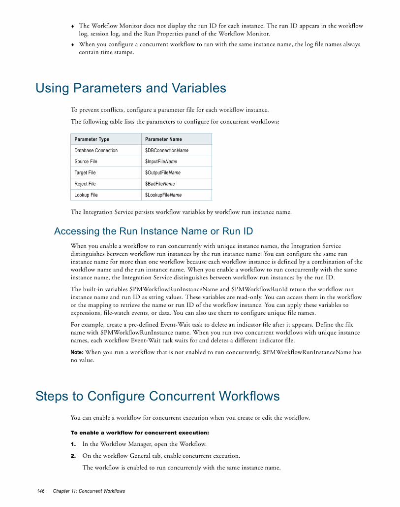
♦ The Workflow Monitor does not display the run ID for each instance. The run ID appears in the workflow log, session log, and the Run Properties panel of the Workflow Monitor.
♦ When you configure a concurrent workflow to run with the same instance name, the log file names always contain time stamps.
Using Parameters and VariablesTo prevent conflicts, configure a parameter file for each workflow instance.
The following table lists the parameters to configure for concurrent workflows:
The Integration Service persists workflow variables by workflow run instance name.
Accessing the Run Instance Name or Run IDWhen you enable a workflow to run concurrently with unique instance names, the Integration Service distinguishes between workflow run instances by the run instance name. You can configure the same run instance name for more than one workflow because each workflow instance is defined by a combination of the workflow name and the run instance name. When you enable a workflow to run concurrently with the same instance name, the Integration Service distinguishes between workflow run instances by the run ID.
The built-in variables $PMWorkflowRunInstanceName and $PMWorkflowRunId return the workflow run instance name and run ID as string values. These variables are read-only. You can access them in the workflow or the mapping to retrieve the name or run ID of the workflow instance. You can apply these variables to expressions, file-watch events, or data. You can also use them to configure unique file names.
For example, create a pre-defined Event-Wait task to delete an indicator file after it appears. Define the file name with $PMWorkflowRunInstance name. When you run two concurrent workflows with unique instance names, each workflow Event-Wait task waits for and deletes a different indicator file.
Note: When you run a workflow that is not enabled to run concurrently, $PMWorkflowRunInstanceName has no value.
Steps to Configure Concurrent WorkflowsYou can enable a workflow for concurrent execution when you create or edit the workflow.
To enable a workflow for concurrent execution:
1. In the Workflow Manager, open the Workflow.
2. On the workflow General tab, enable concurrent execution.
The workflow is enabled to run concurrently with the same instance name.
Parameter Type Parameter Name
Database Connection $DBConnectionName
Source File $InputFileName
Target File $OutputFileName
Reject File $BadFileName
Lookup File $LookupFileName
146 Chapter 11: Concurrent Workflows

3. To configure different instance names, click Configure Concurrent Execution.
The Configure Concurrent Execution dialog box appears.
4. Choose one of the following options:
♦ Allow concurrent run only with unique instance name. The Integration Service can run concurrent workflows if the instance names are unique.
♦ Allow concurrent run with the same instance name. The Integration Service can run concurrent workflows with the same name.
5. Optionally, click the Add button to add workflow instance names.
The workflow instance name is not case sensitive. The Workflow Designer validates the characters in the instance name. You cannot use the following special characters in the instance name:
$ . + - = ~ ` ! % ^ & * () [] {} ' \ " ; : / ? , < > \\ | \t \r \n
6. Optionally, enter the path to a workflow parameter file for the instance. To use different sources, targets, or variables for each workflow instance, configure a parameter file for each instance.
7. Click OK.
Starting and Stopping Concurrent WorkflowsYou can start concurrent workflows in the Workflow Designer or the Workflow Monitor. You can also start workflows from pmcmd. To run unique workflow instances choose the instances to run when you start the workflow.
Starting Workflow Instances from Workflow DesignerYou can choose which workflow instances to run when you start a workflow from the Workflow Designer. Follow these steps to start a workflow that has at least one instance defined.
To start workflow instances from the Workflow Designer:
1. Open the folder containing the workflow.
2. From the Navigator, select the workflow that you want to start.
3. Right-click the workflow and select Start Workflow Advanced.
4. Choose the workflow run instances to start. By default, all instances are selected. You can clear all the workflow instances and choose the instances to start.
5. Click OK to start the workflow instances.
The Workflow Monitor displays each concurrent workflow name and instance name.
Starting One Concurrent WorkflowWhen a concurrent workflow does not have unique instance names or when you do not want to run the configured instances, you can start a workflow with the Workflow Designer. If you start the concurrent workflow with the Start Workflow option, the Integration Service runs the workflow with the attributes and variables you define on the workflow Properties and Variables tabs. The Integration Service does not run any of the configured workflow instances.
To start one concurrent workflow instance:
1. Open the folder containing the workflow.
2. From the Navigator, select the workflow that you want to start.
Starting and Stopping Concurrent Workf lows 147

3. Right-click the workflow in the Navigator and choose Start Workflow.
The Integration Service runs one instance of the workflow with the attributes from the workflow Properties and Variables tabs.
Starting Concurrent Workflows from the Command LineYou can start one workflow instance at a time from the command line. The pmcmd startworkflow command has a parameter for an instance name. When you start a workflow from the command line and you enter an instance name parameter, the Integration Service runs that instance of the workflow. To run more than one workflow instance, run the pmcmd startworkflow command multiple times.
If you do not enter an instance name parameter with startworkflow, the Integration Service runs the workflow with the attributes and variables you define on the workflow Properties and Variables tabs. The Integration Service does not run any of the configured workflow instances.
Creating Workflow Instances from the Command LineYou can dynamically create an instance when you start the workflow with pmcmd. Enter an instance name and parameter file name. If the instance name is not configured, the Integration Service generates an instance. The Integration Service can persist variables for the instance in the repository, but the instance does not appear on the Concurrent Execution Configuration dialog box for the workflow.
Stopping or Aborting Concurrent WorkflowsYou can stop or abort a concurrent workflow from the Workflow Monitor or pmcmd. To stop or abort the workflow from the Workflow Monitor, right-click workflow in the Navigator and select Stop or Abort. The Workflow Monitor displays the status of the stop or abort command in the Output window.
To stop or abort a concurrent workflow from pmcmd, identify the workflow instance by entering the instance name or the workflow run ID parameter on the command line. To stop or abort a task in a concurrent workflow, enter the workflow instance name or run ID of the concurrent workflow that contains the task to stop. When a concurrent workflow does not have unique instance names, you can find the workflow run ID in the workflow log or the workflow run properties of the Workflow Monitor.
Monitoring Concurrent WorkflowsWhen you run a concurrent workflow, the Workflow Monitor displays each workflow run by workflow name. If the workflow has a unique instance name, the Workflow Monitor displays the instance name with the workflow name.
The following figure shows concurrent workflow and instance names in the Workflow Monitor Task view:
When you view concurrent workflows in Gantt Chart View, the Workflow Monitor displays one timeline for each workflow name or workflow instance name. You can scroll the Time Window to view information about specific workflow runs.
When the workflow has unique instance names, the Workflow Monitor displays the instance name for each workflow run.
148 Chapter 11: Concurrent Workflows

Viewing Session and Workflow LogsThe Integration Service names concurrent workflow session and workflow log files based on the way you configure concurrency:
♦ Unique instance names. The Integration Service appends the instance name to the log file name.
♦ Instances of the same name. The Integration Service appends a run ID and time stamp to the log file name.
The Integration Service writes the run ID and the workflow type to the workflow log. The workflow type describes if the workflow is a concurrent workflow.
For example:
Workflow SALES_REV started with run id [108], run instance name [WF_CONCURRENT_SALES1], run type [Concurrent Run with Unique Instance Name].
Each session log also includes an entry that describes the workflow run ID and instance name:
Workflow: [SALES_REV] Run Instance Name: [WF_CONCURRENT_SALES1] Run Id: [108]
Log Files for Unique Workflow InstancesWhen you configure a workflow to run concurrently with unique instance names, the Integration Service creates logs for each instance. Each log file name includes the instance name:
<workflow_name>.<workflow_instance_name><session_name>.<workflow_instance_name>
For example if the workflow log file name is wf_store_sales.log, and the instance name is store1_workflow, the Integration Service creates the following log file names for the binary workflow log file and the text workflow log file:
wf_store_sales.log.store1_workflow.binwf_store_sales.log.store1_workflow
To avoid overwriting the log files, you can archive the log files or save the log files by time stamp.
Log Files for Workflow Instances of the Same NameWhen you configure the workflow to run concurrently with the same instance name, the Integration Service creates logs for each instance. Each log file name includes a run ID and time stamp by default:
<workflow_name>.<runID>.<timestamp><session_name>.<run ID>.<timestamp>
For example if the workflow log file name is wf_store_sales.log, and the run ID is 845, the Integration Service creates the following log file names for the binary workflow log file and the text workflow log file if workflow runs on July 12, 2007 at 11:20:45:
wf_store_sales.log.845.20070712112045.binwf_store_sales.log.845.20070712112045
When you configure the workflow to run concurrently with the same instance name, and you also define instance names, the Integration Service appends the instance name and the time stamp to the log file name. For example:
<workflow_name>.<instance_name>.<run ID>.20070712112045.bin<session_name>.<instance_name>.<run ID>.20070712112045.bin
The Integration Service writes the instance name and run ID to the workflow log. For example:
Workflow wf_Stores started with run ID[86034], run instance name[Store1_workflow]
Viewing Session and Workflow Logs 149

Rules and Guidelines for Concurrent WorkflowsUse the following rules and guidelines for concurrent workflows:
♦ You cannot reference workflow run instances in parameter files. To use separate parameters for each instance, you must configure different parameter files.
♦ If you use the same cache file name for more than one concurrent workflow instance, each workflow instance will be valid. However, sessions will fail if conflicts occur writing to the cache.
♦ You can use pmcmd to restart concurrent workflows by run ID or instance name.
♦ If you configure multiple instances of a workflow and you schedule the workflow, the Integration Service runs all instances at the scheduled time. You cannot run instances on separate schedules.
♦ Configure a worklet to run concurrently on the worklet General tab.
♦ You must enable a worklet to run concurrently if the parent workflow is enabled to run concurrently. Otherwise the workflow is invalid.
♦ You can enable a worklet to run concurrently and place it in two non-concurrent workflows. The Integration Service can run the two worklets concurrently.
♦ Two workflows enabled to run concurrently can run the same worklet. One workflow can run two instances of the same worklet if the worklet has no persisted variables.
♦ A session in a worklet can run concurrently with a session in another worklet of the same instance name when the session does not contain persisted variables.
The following transformations have restrictions with concurrent workflows:
♦ Aggregator transformation. You cannot use an incremental aggregation in a concurrent workflow. The session fails.
♦ Lookup transformation. Use the following rules and guidelines for Lookup transformations in concurrent workflows:
− You can use static or dynamic lookup cache with concurrent workflows.
− When the cache is non-persistent, the Integration Service adds the workflow run ID as a prefix to the cache file name.
− When the cache is an unnamed persistent cache, the Integration Service adds the run instance name as a prefix to the cache file name.
− If the cache is a dynamic, unnamed, persistent cache and the current workflow is configured to allow concurrent runs with the same instance name, the session fails.
− If the lookup cache name is parameterized, the Integration Service names the cache file with the parameter value. Pass a different file name for each run instance.
♦ Sequence Generator transformation. To avoid generating the same set of sequence numbers for concurrent workflows, configure the number of cached values in the Sequence Generator transformation.
150 Chapter 11: Concurrent Workflows

C H A P T E R 1 2
Grid Processing
This chapter includes the following topics:
♦ Overview, 151
♦ Running Workflows on a Grid, 152
♦ Running Sessions on a Grid, 152
♦ Working with Partition Groups, 153
♦ Grid Connectivity and Recovery, 155
♦ Configuring a Workflow or Session to Run on a Grid, 155
OverviewWhen a PowerCenter domain contains multiple nodes, you can configure workflows and sessions to run on a grid. When you run a workflow on a grid, the Integration Service runs a service process on each available node of the grid to increase performance and scalability. When you run a session on a grid, the Integration Service distributes session threads to multiple DTM processes on nodes in the grid to increase performance and scalability.
You create the grid and configure the Integration Service in the Administration Console. To run a workflow on a grid, you configure the workflow to run on the Integration Service associated with the grid. To run a session on a grid, configure the session to run on the grid.
Figure 12-1 shows the relationship between the workflow and nodes when you run a workflow on a grid:
The Integration Service distributes workflow tasks and session threads based on how you configure the workflow or session to run:
♦ Running workflows on a grid. The Integration Service distributes workflows across the nodes in a grid. It also distributes the Session, Command, and predefined Event-Wait tasks within workflows across the nodes in a grid.
Figure 12-1. Running a Workflow on a Grid
Assign a workflow to run on an Integration Service.
The Integration Service is associated with a grid.
The grid is assigned to multiple nodes.
Node 1
Node 2
Node 3
Workflow Integration Service
Grid
The workflow runs on the nodes in the grid.
Overview 151

♦ Running sessions on a grid. The Integration Service distributes session threads across nodes in a grid.
Note: To run workflows on a grid, you must have the Server grid option. To run sessions on a grid, you must have the Session on Grid option.
Running Workflows on a GridWhen you run a workflow on a grid, the master service process runs the workflow and all tasks except Session, Command, and predefined Event-Wait tasks, which it may distribute to other nodes. The master service process is the Integration Service process that runs the workflow, monitors service processes running on other nodes, and runs the Load Balancer. The Scheduler runs on the master service process node, so it uses the date and time for the master service process node to start scheduled workflows.
The Load Balancer is the component of the Integration Service that dispatches Session, Command, and predefined Event-Wait tasks to the nodes in the grid. The Load Balancer distributes tasks based on node availability. If the Integration Service is configured to check resources, the Load Balancer also distributes tasks based on resource availability.
For example, a workflow contains a Session task, a Decision task, and a Command task. You specify a resource requirement for the Session task. The grid contains four nodes, and Node 4 is unavailable. The master service process runs the Start and Decision tasks. The Load Balancer distributes the Session and Command tasks to nodes on the grid based on resource availability and node availability.
Figure 12-2 shows a workflow distributed to the nodes in a grid:
Running Sessions on a GridWhen you run a session on a grid, the master service process runs the workflow and all tasks except Session, Command, and predefined Event-Wait tasks as it does when you run a workflow on a grid. The Scheduler runs on the master service process node, so it uses the date and time for the master service process node to start scheduled workflows. In addition, the Load Balancer distributes session threads to DTM processes running on different nodes.
When you run a session on a grid, the Load Balancer distributes session threads based on the following factors:
♦ Node availability. The Load Balancer verifies which nodes are currently running, enabled, and available for task dispatch.
♦ Resource availability. If the Integration Service is configured to check resources, it identifies nodes that have resources required by mapping objects in the session.
Figure 12-2. Workflow Distributed to the Nodes in a Grid
Start task runs on the master service process node.
Node 1 Node 2 Node 3
Session task runs on node where resources are available.
Command task runs on node where resources are available.
Node 1
Decision task runs on master service process node.
152 Chapter 12: Grid Processing

♦ Partitioning configuration. The Load Balancer dispatches groups of session threads to separate nodes based on the partitioning configuration.
You might want to configure a session to run on a grid when the workflow contains a session that takes a long time to run.
For example, a workflow contains a session with one partition. To balance the load, you configure the session to run on a grid and configure the Integration Service to check resources. The Load Balancer distributes the reader, writer, and transformation threads to DTM processes running on the nodes in the grid. The reader threads require a resource, so the Load Balancer distributes them to a DTM process on the node where resources are available.
Figure 12-3 shows session threads distributed to DTM processes running on nodes in a grid:
RELATED TOPICS:♦ “Assigning Resources to Tasks” on page 158
Working with Partition GroupsWhen you run a session on a grid, the Data Transformation Manager process (DTM) forms groups of session threads called partition groups. A partition group is a group of reader, writer, or transformation threads that run in a single DTM process. A partition group might include one or more pipeline stages. A pipeline stage is the section of a pipeline executed between any two partition points. Some transformations are not partitionable across a grid. When a transformation is not partitionable across a grid, the DTM creates a single partition group for the transformation threads and runs those threads on a single node.
Forming Partition Groups Without Resource RequirementsIf the session has more than one partition, the DTM forms partition groups based on the partitioning configuration. For example, a session is configured with two partitions. The DTM creates partition groups for the threads in each partition, and the Load Balancer distributes the groups to two nodes.
Figure 12-3. Session Threads Distributed to DTM Processes Running on Nodes in a Grid
Node 4 is unavailable so no threads run on it.
Node 1 Node 2 Node 3 Node 4
Reader threads run on node where resources are available.
Writer threads run on available node.
Transformation threads run on available node.
Working with Partition Groups 153

Figure 12-4 shows partition groups distributed for a session containing two partitions:
Forming Partition Groups With Resource RequirementsWhen you specify resource requirements for a mapping object, the DTM process creates partition groups based on the resources available on a particular node. For example, if the source files for the session are available on a particular node and you specified a resource requirement for the Source Qualifier transformation, the DTM process forms partition groups based on this requirement.
To meet the resource requirements of the Source Qualifier transformation, the DTM process creates a partition group from the reader threads. The Load Balancer distributes the reader threads to the node where the resource is available.
Note: To cause the Load Balancer to distribute threads to nodes where required resources are available, you must configure the Integration Service to check resources.
Figure 12-5 shows partition groups distributed based on partitioning configuration and resource availability:
Rules and GuidelinesThe Integration Service uses the following rules and guidelines to create partition groups:
♦ The Integration Service limits the number of partition groups to the number of nodes in a grid.
♦ When a transformation is partitionable locally, the DTM process forms one partition group for the transformation threads, and runs that group in one DTM process. The following transformations are partitioned locally:
− Custom transformation configured to partition locally
− External Procedure transformation
− Cached Lookup transformation
− Unsorted Joiner transformation
− SDK Reader or Writer transformation configured to partition locally
Working with CachesThe Integration Service creates index and data caches for the Aggregator, Rank, Joiner, Sorter, and Lookup transformations. When the session contains more than one partition, the transformation threads may be
Figure 12-4. Partition Groups Distributed Based on Partitioning Configuration
Figure 12-5. Partition Groups Distributed Based on Resource Availability
Reader 1 Transformation 1 Writer 1 Node 1
Node 2Reader 2 Transformation 2 Writer 2
Partition 1
Partition 2
Partition Group 1 runs on Node 1.
Partition Group 2 runs on Node 2.
Reader 1 Transformation 1 Writer 1
Node 1 Node 2
Reader 2 Transformation 2 Writer 2
Partition 1
Partition 2
Partition Group 1 runs on Node 1 where resources are available.
Partition Group 2 runs on Node 2.
154 Chapter 12: Grid Processing

distributed to more than one node in the grid. To create a single data and index cache for these transformation threads, verify that the root directory and cache directory point to the same location for all nodes in the grid.
When the Integration Service creates a cache for a Lookup transformation in a shared location, it builds a cache for the first partition group, and subsequent partition groups use this cache. When you do not configure a shared location for the Lookup transformation cache files, each service process on a separate node fetches data from the database or source files to create a cache. If the source data changes frequently, the caches created on separate nodes can be inconsistent.
RELATED TOPICS:♦ “Session Caches” on page 233
Grid Connectivity and RecoveryWhen you run a workflow or session on a grid, service processes and DTM processes run on different nodes. Network failures can cause connectivity loss between processes running on separate nodes. Services may shut down unexpectedly, or you may disable the Integration Service or service processes while a workflow or session is running. The Integration Service failover and recovery behavior in these situations depends on the service process that is disabled, shuts down, or loses connectivity. Recovery behavior also depends on the following factors:
♦ High availability option. When you have high availability, workflows fail over to another node if the node or service shuts down. If you do not have high availability, you can manually restart a workflow on another node to recover it.
♦ Recovery strategy. You can configure a workflow to suspend on error. You configure a recovery strategy for tasks within the workflow. When a workflow suspends, the recovery behavior depends on the recovery strategy you configure for each task in the workflow.
♦ Shutdown mode. When you disable an Integration Service or service process, you can specify that the service completes, aborts, or stops processes running on the service. Behavior differs when you disable the Integration Service or you disable a service process. Behavior also differs when you disable a master service process or a worker service process. The Integration Service or service process may also shut down unexpectedly. In this case, the failover and recovery behavior depend on which service process shuts down and the configured recovery strategy.
♦ Running mode. If the workflow runs on a grid, the Integration Service can recover workflows and tasks on another node. If a session runs on a grid, you cannot configure a resume recovery strategy.
♦ Operating mode. If the Integration Service runs in safe mode, recovery is disabled for sessions and workflows.
Note: You cannot configure an Integration Service to fail over in safe mode if it runs on a grid.
RELATED TOPICS:♦ “Workflow Recovery” on page 123
Configuring a Workflow or Session to Run on a GridBefore you can run a session or workflow on a grid, the grid must be assigned to multiple nodes, and the Integration Service must be configured to run on the grid. You create the grid and assign the Integration Service in the PowerCenter Administration Console. You may need to verify these settings with the domain administrator.
Grid Connectivity and Recovery 155

To run a workflow or session on a grid, configure the following properties and settings:
♦ Workflow properties. On the General tab of the workflow properties, assign an Integration Service to run the workflow. Verify that the Integration Service is configured to run on a grid.
♦ Session properties. To run a session on a grid, enable the session to run on a grid in the Config Object tab of the session properties.
♦ Resource requirements. You configure resource requirements on the General tab of the Session, Command, and predefined Event-Wait tasks.
RELATED TOPICS:♦ “Assigning Resources to Tasks” on page 158
Rules and GuidelinesUse the following rules and guidelines when you configure a session or workflow to run on a grid:
♦ If you override a service process variable, ensure that the Integration Service can access input files, caches, logs, storage and temporary directories, and source and target file directories.
♦ To ensure that a Session, Command, or predefined Event-Wait task runs on a particular node, configure the Integration Service to check resources and specify a resource requirement for a the task.
♦ To ensure that session threads for a mapping object run on a particular node, configure the Integration Service to check resources and specify a resource requirement for the object.
♦ When you run a session that creates cache files, configure the root and cache directory to use a shared location to ensure consistency between cache files.
♦ Ensure the Integration Service builds the cache in a shared location when you add a partition point at a Joiner transformation and the transformation is configured for 1:n partitioning. The cache for the Detail pipeline must be shared.
♦ Ensure the Integration Service builds the cache in a shared location when you add a partition point at a Lookup transformation, and the partition type is not hash auto-keys.
♦ When you run a session that uses dynamic partitioning, and you want to distribute session threads across all nodes in the grid, configure dynamic partitioning for the session to use the “Based on number of nodes in the grid” method.
♦ You cannot run a debug session on a grid.
♦ You cannot configure a resume recovery strategy for a session that you run on a grid.
♦ Configure the session to run on a grid when you work with sessions that take a long time to run.
♦ Configure the workflow to run on a grid when you have multiple concurrent sessions.
♦ You can run a persistent profile session on a grid, but you cannot run a temporary profile session on a grid.
♦ When you use a Sequence Generator transformation, increase the number of cached values to reduce the communication required between the master and worker DTM processes and the repository.
♦ To ensure that the Log Viewer can accurately order log events when you run a workflow or session on a grid, use time synchronization software to ensure that the nodes of a grid use a synchronized date/time.
♦ If the workflow uses an Email task in a Windows environment, configure the same Microsoft Outlook profile on each node to ensure the Email task can run.
156 Chapter 12: Grid Processing

C H A P T E R 1 3
Load Balancer
This chapter includes the following topics:
♦ Overview, 157
♦ Assigning Service Levels to Workflows, 157
♦ Assigning Resources to Tasks, 158
OverviewThe Load Balancer dispatches tasks to Integration Service processes running on nodes. When you run a workflow, the Load Balancer dispatches the Session, Command, and predefined Event-Wait tasks within the workflow. If the Integration Service is configured to check resources, the Load Balancer matches task requirements with resource availability to identify the best node to run a task. It may dispatch tasks to a single node or across nodes.
To identify the nodes that can run a task, the Load Balancer matches the resources required by the task with the resources available on each node. It dispatches tasks in the order it receives them. When the Load Balancer has more Session and Command tasks to dispatch than the Integration Service can run at the time, the Load Balancer places the tasks in the dispatch queue. When nodes become available, the Load Balancer dispatches the waiting tasks from the queue in the order determined by the workflow service level.
You assign resources and service levels using the Workflow Manager. You can perform the following tasks:
♦ Assign service levels. You assign service levels to workflows. Service levels establish priority among workflow tasks that are waiting to be dispatched.
♦ Assign resources. You assign resources to tasks. Session, Command, and predefined Event-Wait tasks require PowerCenter resources to succeed. If the Integration Service is configured to check resources, the Load Balancer dispatches these tasks to nodes where the resources are available.
Assigning Service Levels to WorkflowsService levels determine the order in which the Load Balancer dispatches tasks from the dispatch queue. When multiple tasks are waiting to be dispatched, the Load Balancer dispatches high priority tasks before low priority tasks. You create service levels and configure the dispatch priorities in the Administration Console.
You assign service levels to workflows on the General tab of the workflow properties.
157

Assigning Resources to TasksPowerCenter resources are the database connections, files, directories, node names, and operating system types required by a task to make the task succeed. The Load Balancer may use resources to dispatch tasks. If the Integration Service is not configured to run on a grid or check resources, the Load Balancer ignores resource requirements. It dispatches all tasks to the master Integration Service process running on the node.
If the Integration Service runs on a grid and is configured to check resources, the Load Balancer uses resources to dispatch tasks. The Integration Service matches the resources required by tasks in a workflow with the resources available on each node in the grid to determine which nodes can run the tasks. The Load Balancer distributes the Session, Command, and predefined Event-Wait tasks to nodes with available resources. For example, if a session requires a file resource for a reserved words file, the Load Balancer dispatches the session to nodes that have access to the file. A task fails if the Integration Service cannot identify a node where the required resource is available.
In the Administration Console, you define the resources that are available to each node. Resources are either predefined or user-defined. Predefined resources include connections available to a node, node name, and operating system type. User-defined resources include file/directory resources and custom resources.
In the task properties, you assign PowerCenter resources to nonreusable tasks that require those resources. You cannot assign resources to reusable tasks.
The following table lists resource types and the repository objects to which you can assign them:
If you try to assign a resource type that does not apply to a repository object, the Workflow Manager displays the following error message:
The selected resource cannot be applied to this type of object. Please select a different resource.
The Workflow Manager assigns connection resources. When you use a relational, FTP, or external loader connection, the Workflow Manager assigns the connection resource to sources, targets, and transformations in a session instance. You cannot manually assign a connection resource in the Workflow Manager.
Resource Type
Predefined/User-Defined Repository Objects that Use Resources
Custom User-defined Session, Command, and predefined Event-Wait task instances and all mapping objects within a session.
File/Directory User-defined Session, Command, and predefined Event-Wait task instances, and the following mapping objects within a session:- Source qualifiers- Aggregator transformation- Custom transformation- External Procedure transformation- Joiner transformation- Lookup transformation- Sorter transformation- Custom transformation- Java transformation- HTTP transformation- SQL transformation- Union transformation- Targets
Node Name Predefined Session, Command, and predefined Event-Wait task instances and all mapping objects within a session.
Operating System Type
Predefined Session, Command, and predefined Event-Wait task instances and all mapping objects within a session.
158 Chapter 13: Load Balancer

To assign resources to a task instance:
1. Open the task properties in the Worklet or Workflow Designer.
If the task is an Event-Wait task, you can assign resources only if the task waits for a predefined event.
2. On the General tab, click Edit.
3. In the Edit Resources dialog box, click the Add button to add a resource.
4. In the Select Resource dialog box, choose an object you want to assign a resource to. The Resources list shows the resources available to the nodes where the Integration Service runs.
5. Select the resource to assign and click Select.
6. In the Edit Resources dialog box, click OK.
Assigning Resources to Tasks 159

160 Chapter 13: Load Balancer

C H A P T E R 1 4
Workflow Variables
This chapter includes the following topics:
♦ Overview, 161
♦ Predefined Workflow Variables, 162
♦ User-Defined Workflow Variables, 166
♦ Using Worklet Variables, 169
♦ Assigning Variable Values in a Worklet, 170
OverviewYou can create and use variables in a workflow to reference values and record information. For example, use a variable in a Decision task to determine whether the previous task ran properly. If it did, you can run the next task. If not, you can stop the workflow.
Use the following types of workflow variables:
♦ Predefined workflow variables. The Workflow Manager provides predefined workflow variables for tasks within a workflow. For more information, see “Predefined Workflow Variables” on page 162.
♦ User-defined workflow variables. You create user-defined workflow variables when you create a workflow. For more information, see “User-Defined Workflow Variables” on page 166.
Use workflow variables when you configure the following types of tasks:
♦ Assignment tasks. Use an Assignment task to assign a value to a user-defined workflow variable. For example, you can increment a user-defined counter variable by setting the variable to its current value plus 1.
♦ Decision tasks. Decision tasks determine how the Integration Service runs a workflow. For example, use the Status variable to run a second session only if the first session completes successfully.
♦ Links. Links connect each workflow task. Use workflow variables in links to create branches in the workflow. For example, after a Decision task, you can create one link to follow when the decision condition evaluates to true, and another link to follow when the decision condition evaluates to false.
♦ Timer tasks. Timer tasks specify when the Integration Service begins to run the next task in the workflow. Use a user-defined date/time variable to specify the time the Integration Service starts to run the next task.
Use the Expression Editor to create an expression that uses variables. When you build an expression, you can select predefined variables on the Predefined tab. You can select user-defined variables on the User-Defined tab. The Functions tab contains functions that you use with workflow variables. Use the point-and-click method to enter an expression using a variable.
161

Use the following keywords to write expressions for user-defined and predefined workflow variables:
♦ AND
♦ OR
♦ NOT
♦ TRUE
♦ FALSE
♦ NULL
♦ SYSDATE
Predefined Workflow VariablesEach workflow contains a set of predefined variables that you use to evaluate workflow and task conditions. Use the following types of predefined variables:
♦ Task-specific variables. The Workflow Manager provides a set of task-specific variables for each task in the workflow. Use task-specific variables in a link condition to control the path the Integration Service takes when running the workflow. The Workflow Manager lists task-specific variables under the task name in the Expression Editor.
♦ Built-in variables. Use built-in variables in a workflow to return run-time or system information such as folder name, Integration Service Name, system date, or workflow start time. The Workflow Manager lists built-in variables under the Built-in node in the Expression Editor. For more information about built-in variables, see the PowerCenter Transformation Language Reference.
Tip: When you set the error severity level for log files to Tracing in the PowerCenter Server setup, the workflow log displays the values of workflow variables. Use this logging level for troubleshooting only.
The following table lists the task-specific workflow variables available in the Workflow Manager:
Task-SpecificVariables Description Task
Types Datatype
Condition Evaluation result of decision condition expression.If the task fails, the Workflow Manager keeps the condition set to null.Sample syntax:$Dec_TaskStatus.Condition = <TRUE | FALSE | NULL | any integer>
Decision Integer
EndTime Date and time the associated task ended. Precision is to the second.Sample syntax:$s_item_summary.EndTime > TO_DATE('11/10/2004 08:13:25')
All tasks Date/Time
ErrorCode Last error code for the associated task. If there is no error, the Integration Service sets ErrorCode to 0 when the task completes.Sample syntax:$s_item_summary.ErrorCode = 24013Note: You might use this variable when a task consistently fails with this final error message.
All tasks Integer
162 Chapter 14: Workflow Variables

ErrorMsg Last error message for the associated task.If there is no error, the Integration Service sets ErrorMsg to an empty string when the task completes.Sample syntax:$s_item_summary.ErrorMsg = 'PETL_24013 Session run completed with failureNote: You might use this variable when a task consistently fails with this final error message.
All tasks Nstring*
FirstErrorCode Error code for the first error message in the session.If there is no error, the Integration Service sets FirstErrorCode to 0 when the session completes.Sample syntax:$s_item_summary.FirstErrorCode = 7086
Session Integer
FirstErrorMsg First error message in the session.If there is no error, the Integration Service sets FirstErrorMsg to an empty string when the task completes.Sample syntax:$s_item_summary.FirstErrorMsg = 'TE_7086 Tscrubber: Debug info… Failed to evalWrapUp'
Session Nstring*
PrevTaskStatus Status of the previous task in the workflow that the Integration Service ran. Statuses include:- ABORTED- FAILED- STOPPED- SUCCEEDEDUse these key words when writing expressions to evaluate the status of the previous task. Sample syntax:$Dec_TaskStatus.PrevTaskStatus = FAILED
All tasks Integer
SrcFailedRows Total number of rows the Integration Service failed to read from the source.Sample syntax:$s_dist_loc.SrcFailedRows = 0
Session Integer
SrcSuccessRows Total number of rows successfully read from the sources.Sample syntax:$s_dist_loc.SrcSuccessRows > 2500
Session Integer
StartTime Date and time the associated task started. Precision is to the second.Sample syntax:$s_item_summary.StartTime > TO_DATE('11/10/2004 08:13:25')
All tasks Date/Time
Status Status of the previous task in the workflow. Statuses include:- ABORTED- DISABLED- FAILED- NOTSTARTED- STARTED- STOPPED- SUCCEEDEDUse these key words when writing expressions to evaluate the status of the current task. Sample syntax:$s_dist_loc.Status = SUCCEEDED
All tasks Integer
Task-SpecificVariables Description Task
Types Datatype
Predefined Workf low Variables 163

All predefined workflow variables except Status have a default value of null. The Integration Service uses the default value of null when it encounters a predefined variable from a task that has not yet run in the workflow. Therefore, expressions and link conditions that depend upon tasks not yet run are valid. The default value of Status is NOTSTARTED.
RELATED TOPICS:♦ “Evaluating Task Status in a Workflow” on page 165
Using Predefined Workflow Variables in ExpressionsWhen you use a workflow variable in an expression, the Integration Service evaluates the expression and returns True or False. If the condition evaluates to true, the Integration Service runs the next task. The Integration Service writes an entry in the workflow log similar to the following message:
INFO : LM_36506 : (1980|1040) Link [Session2 --> Session3]: condition is TRUE for the expression [$Session2.PrevTaskStatus = SUCCEEDED].
The Expression Editor displays the predefined workflow variables on the Predefined tab. The Workflow Manager groups task-specific variables by task and lists built-in variables under the Built-in node. To use a variable in an expression, double-click the variable. The Expression Editor displays task-specific variables in the Expression field in the following format:
$<TaskName>.<predefinedVariable>
Evaluating Condition in a WorkflowUse Condition in link conditions to evaluate the result of a decision condition expression.
TgtFailedRows Total number of rows the Integration Service failed to write to the target.Sample syntax:$s_dist_loc.TgtFailedRows = 0
Session Integer
TgtSuccessRows Total number of rows successfully written to the targetSample syntax:$s_dist_loc.TgtSuccessRows > 0
Session Integer
TotalTransErrors Total number of transformation errors.Sample syntax:$s_dist_loc.TotalTransErrors = 5
Session Integer
* Variables of type Nstring can have a maximum length of 600 characters.
Task-SpecificVariables Description Task
Types Datatype
164 Chapter 14: Workflow Variables
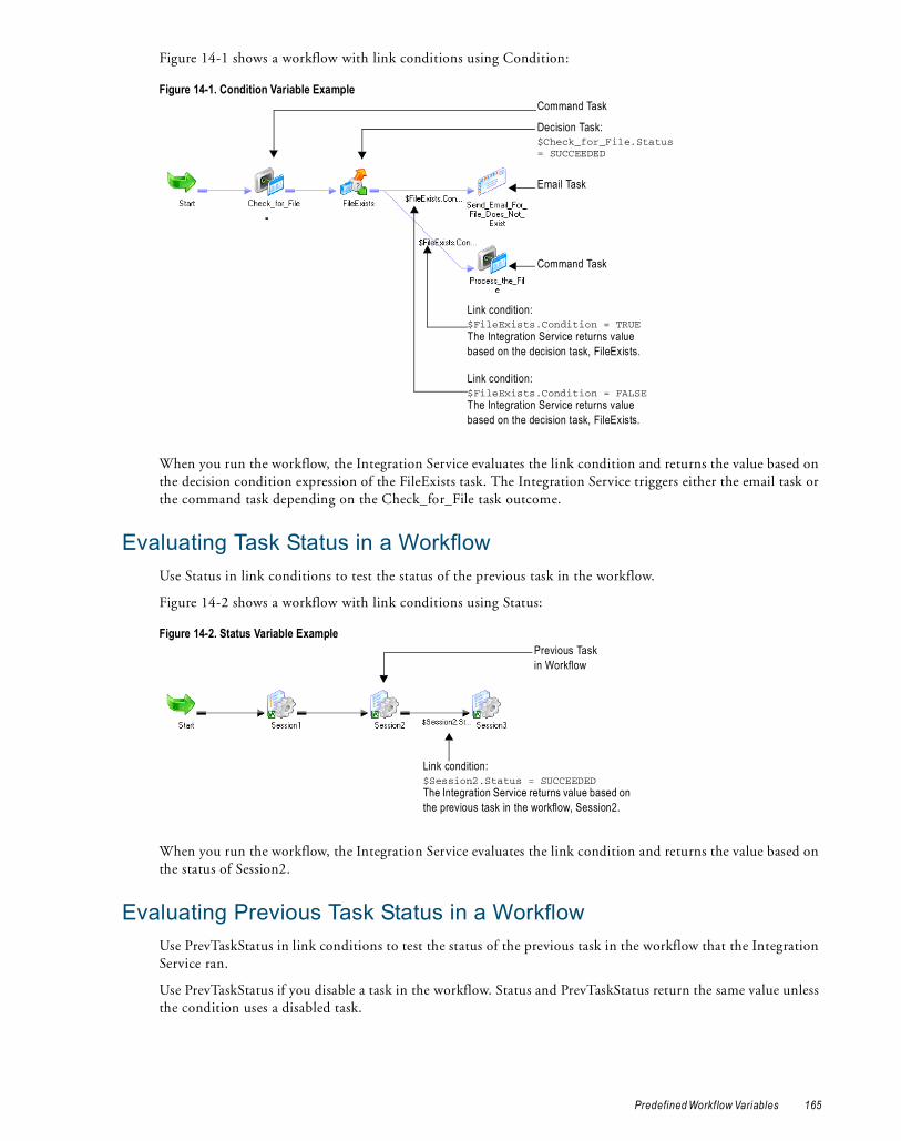
Figure 14-1 shows a workflow with link conditions using Condition:
When you run the workflow, the Integration Service evaluates the link condition and returns the value based on the decision condition expression of the FileExists task. The Integration Service triggers either the email task or the command task depending on the Check_for_File task outcome.
Evaluating Task Status in a WorkflowUse Status in link conditions to test the status of the previous task in the workflow.
Figure 14-2 shows a workflow with link conditions using Status:
When you run the workflow, the Integration Service evaluates the link condition and returns the value based on the status of Session2.
Evaluating Previous Task Status in a WorkflowUse PrevTaskStatus in link conditions to test the status of the previous task in the workflow that the Integration Service ran.
Use PrevTaskStatus if you disable a task in the workflow. Status and PrevTaskStatus return the same value unless the condition uses a disabled task.
Figure 14-1. Condition Variable Example
Figure 14-2. Status Variable Example
Decision Task:$Check_for_File.Status = SUCCEEDED
Command Task
Link condition:$FileExists.Condition = TRUEThe Integration Service returns value based on the decision task, FileExists.
Link condition:$FileExists.Condition = FALSEThe Integration Service returns value based on the decision task, FileExists.
Email Task
Command Task
Link condition:$Session2.Status = SUCCEEDEDThe Integration Service returns value based on the previous task in the workflow, Session2.
Previous Task in Workflow
Predefined Workf low Variables 165

Figure 14-3 shows a workflow with link conditions using PrevTaskStatus:
When you run the workflow, the Integration Service skips Session2 because the session is disabled. When the Integration Service evaluates the link condition, it returns the value based on the status of Session1.
Tip: If you do not disable Session2, the Integration Service returns the value based on the status of Session2. You do not need to change the link condition when you enable and disable Session2.
User-Defined Workflow VariablesYou can create variables within a workflow. When you create a variable in a workflow, it is valid only in that workflow. Use the variable in tasks within that workflow. You can edit and delete user-defined workflow variables.
Use user-defined variables when you need to make a workflow decision based on criteria you specify. For example, you create a workflow to load data to an orders database nightly. You also need to load a subset of this data to headquarters periodically, every tenth time you update the local orders database. Create separate sessions to update the local database and the one at headquarters.
Figure 14-4 shows the workflow:
Use a user-defined variable to determine when to run the session that updates the orders database at headquarters.
To configure user-defined workflow variables, complete the following steps:
1. Create a persistent workflow variable, $$WorkflowCount, to represent the number of times the workflow has run.
2. Add a Start task and both sessions to the workflow.
3. Place a Decision task after the session that updates the local orders database.
Figure 14-3. PrevTaskStatus Variable Example
Figure 14-4. Workflow Using Workflow Variable
Disabled Task
Link condition:$Session2.PrevTaskStatus = SUCCEEDEDThe Integration Service returns value based on the previous task run, Session1.
Previous Task Run
166 Chapter 14: Workflow Variables

Set up the decision condition to check to see if the number of workflow runs is evenly divisible by 10. Use the modulus (MOD) function to do this.
4. Create an Assignment task to increment the $$WorkflowCount variable by one.
5. Link the Decision task to the session that updates the database at headquarters when the decision condition evaluates to true. Link it to the Assignment task when the decision condition evaluates to false.
When you configure workflow variables using conditions, the session that updates the local database runs every time the workflow runs. The session that updates the database at headquarters runs every 10th time the workflow runs.
Workflow Variable Start and Current ValuesConceptually, the Integration Service holds two different values for a workflow variable during a workflow run:
♦ Start value of a workflow variable
♦ Current value of a workflow variable
The start value is the value of the variable at the start of the workflow. The start value could be a value defined in the parameter file for the variable, a value saved in the repository from the previous run of the workflow, a user-defined initial value for the variable, or the default value based on the variable datatype.
The Integration Service looks for the start value of a variable in the following order:
1. Value in parameter file
2. Value saved in the repository (if the variable is persistent)
3. User-specified default value
4. Datatype default value
For more information about datatype default values, see Table 14-1 on page 168.
For example, you create a workflow variable in a workflow and enter a default value, but you do not define a value for the variable in a parameter file. The first time the Integration Service runs the workflow, it evaluates the start value of the variable to the user-defined default value.
If you declare the variable as persistent, the Integration Service saves the value of the variable to the repository at the end of the workflow run. The next time the workflow runs, the Integration Service evaluates the start value of the variable as the value saved in the repository.
If the variable is non-persistent, the Integration Service does not save the value of the variable. The next time the workflow runs, the Integration Service evaluates the start value of the variable as the user-specified default value.
If you want to override the value saved in the repository before running a workflow, you need to define a value for the variable in a parameter file. When you define a workflow variable in the parameter file, the Integration Service uses this value instead of the value saved in the repository or the configured initial value for the variable.
The current value is the value of the variable as the workflow progresses. When a workflow starts, the current value of a variable is the same as the start value. The value of the variable can change as the workflow progresses if you create an Assignment task that updates the value of the variable.
If the variable is persistent, the Integration Service saves the current value of the variable to the repository at the end of a successful workflow run. If the workflow fails to complete, the Integration Service does not update the value of the variable in the repository.
The Integration Service states the value saved to the repository for each workflow variable in the workflow log.
Datatype Default ValuesIf the Integration Service cannot determine the start value of a variable by any other means, it uses a default value for the variable based on its datatype.
User-Defined Workf low Variables 167

Table 14-1 lists the datatype default values for user-defined workflow variables:
RELATED TOPICS:♦ “Workflow Variable Start and Current Values” on page 167
Creating User-Defined Workflow VariablesYou can create workflow variables for a workflow in the workflow properties.
To create a workflow variable:
1. In the Workflow Designer, create a new workflow or edit an existing one.
2. Select the Variables tab.
3. Click Add.
4. Enter the information in the following table and click OK:
Table 14-1. Datatype Default Values for User-Defined Workflow Variables
Datatype Workflow Manager Default Value
Date/Time 1/1/1753 00:00:00.000000000 A.D.
Double 0
Integer 0
Nstring Empty string
Field Description
Name Variable name. The correct format is $$VariableName. Workflow variable names are not case sensitive.Do not use a single dollar sign ($) for a user-defined workflow variable. The single dollar sign is reserved for predefined workflow variables.
Datatype Datatype of the variable. You can select from the following datatypes:- Date/Time- Double- Integer- Nstring
Persistent Whether the variable is persistent. Enable this option if you want the value of the variable retained from one execution of the workflow to the next.
Default Value Default value of the variable. The Integration Service uses this value for the variable during sessions if you do not set a value for the variable in the parameter file and there is no value stored in the repository.Variables of type Date/Time can have the following formats:- MM/DD/RR- MM/DD/YYYY- MM/DD/RR HH24:MI- MM/DD/YYYY HH24:MI- MM/DD/RR HH24:MI:SS- MM/DD/YYYY HH24:MI:SS- MM/DD/RR HH24:MI:SS.MS- MM/DD/YYYY HH24:MI:SS.MS- MM/DD/RR HH24:MI:SS.US- MM/DD/YYYY HH24:MI:SS.US- MM/DD/RR HH24:MI:SS.NS- MM/DD/YYYY HH24:MI:SS.NSYou can use the following separators: dash (-), slash (/), backslash (\), colon (:), period (.), and space. The Integration Service ignores extra spaces. You cannot use one- or three-digit values for year or the “HH12” format for hour.Variables of type Nstring can have a maximum length of 600 characters.
168 Chapter 14: Workflow Variables

5. To validate the default value of the new workflow variable, click the Validate button.
6. Click Apply to save the new workflow variable.
7. Click OK.
RELATED TOPICS:♦ “Workflow Variable Start and Current Values” on page 167
Using Worklet VariablesWorklet variables are similar to workflow variables. A worklet has the same set of predefined variables as any task. You can also create user-defined worklet variables. Like user-defined workflow variables, user-defined worklet variables can be persistent or non-persistent.
Persistent Worklet VariablesUser-defined worklet variables can be persistent or non-persistent. To create a persistent worklet variable, select Persistent when you create the variable. When you create a persistent worklet variable, the worklet variable retains its value the next time the Integration Service runs the worklet in the parent workflow.
For example, you have a worklet with a persistent variable. Use two instances of the worklet in a workflow to run the worklet twice. You name the first instance of the worklet Worklet1 and the second instance Worklet2.
When you run the workflow, the persistent worklet variable retains its value from Worklet1 and becomes the initial value in Worklet2. After the Integration Service runs Worklet2, it retains the value of the persistent variable in the repository and uses the value the next time you run the workflow.
Worklet variables only persist when you run the same workflow. A worklet variable does not retain its value when you use instances of the worklet in different workflows.
Overriding the Initial ValueFor each worklet instance, you can override the initial value of the worklet variable by assigning a workflow variable to it.
To override the initial value of a worklet variable:
1. Double-click the worklet instance in the Workflow Designer workspace.
2. On the Variables tab, click the Add button in the pre-worklet variable assignment.
3. Click the open button in the User-Defined Worklet Variables field to select a worklet variable.
4. Click Apply.
The worklet variable in this worklet instance has the selected workflow variable as its initial value.
Rules and GuidelinesUse the following rules and guidelines when you work with worklet variables:
♦ You cannot use parent workflow variables in the worklet.
Is Null Whether the default value of the variable is null. If the default value is null, enable this option.
Description Description associated with the variable.
Field Description
Using Worklet Variables 169

♦ You can assign the value of a workflow variable to a worklet variable to initialize it.
♦ You cannot use user-defined worklet variables in the parent workflow.
♦ You can use predefined worklet variables in the parent workflow, just as you use predefined variables for other tasks in the workflow.
Assigning Variable Values in a WorkletYou can update the values of variables before or after a worklet runs. This allows you to pass information from one worklet to another within the same workflow or parent worklet. For example, you have a workflow that contains two worklets that need to increment the same counter. You can increment the counter in the first worklet, pass the updated counter value to the second worklet, and increment the counter again in the second worklet.
You can also pass information from a worklet to a non-reusable session or from a non-reusable session to a worklet as long as the worklet and session are in the same workflow or parent worklet. You can assign variables in reusable and non-reusable worklets.
You can update the values of different variables depending on whether you assign them before or after a worklet runs. You can update the following types of variables before or after a worklet runs:
♦ Pre-worklet variable assignment. You can update user-defined worklet variables before a worklet runs. You can assign these variables the values of parent workflow or worklet variables or the values of mapping variables from other tasks in the workflow or parent worklet.
You can update worklet variables with values from the parent of the worklet. Therefore, if a worklet is in another worklet within a workflow, you can assign values from the parent worklet variables, but not the workflow variables.
♦ Post-worklet variable assignment. You can update parent workflow or worklet variables after the worklet completes. You can assign these variables the values of user-defined worklet variables.
You assign variables on the Variables tab when you edit a worklet.
Passing Variable Values between WorkletsYou can assign variable values in a worklet to pass values from one worklet to any subsequent worklet in the same workflow or parent worklet. For example, a workflow contains two worklets wklt_CreateCustList and wklt_UpdateCustOrders. Worklet wklt_UpdateCustOrders needs to use the value of a worklet variable updated in wklt_CreateCustList.
The following figure shows the workflow:
To pass the worklet variable value from wklt_CreateCustList to wklt_UpdateCustOrders, complete the following steps:
1. Configure worklet wklt_CreateCustList to use a worklet variable, for example, $$URLString1.
2. Configure worklet wklt_UpdateCustOrders to use a worklet variable, for example, $$URLString2.
3. Configure the workflow to use a workflow variable, for example, $$PassURLString.
4. Configure worklet wklt_CreateCustList to assign the value of worklet variable $$URLString1 to workflow variable $$PassURLString after the worklet completes.
170 Chapter 14: Workflow Variables

5. Configure worklet wklt_UpdateCustOrders to assign the value of workflow variable $$PassURLString to worklet variable $$URLString2 before the worklet starts.
Configuring Variable AssignmentsAssign variables on the Variables tab when you edit a worklet. Assign values to the following types of variables before or after a worklet runs:
♦ Pre-worklet variable assignment. Update user-defined worklet variables with the values of parent workflow or worklet variables or the values of mapping variables from other tasks in the workflow or parent worklet that run before this worklet.
♦ Post-worklet variable assignment. Update parent workflow and worklet variables with the values of user-defined worklet variables.
To assign variables in a worklet:
1. Edit the worklet for which you want to assign variables.
2. Click the Variables tab.
3. Select the variable assignment type:
♦ Pre-worklet variable assignment. Assign values to user-defined worklet variables before a worklet runs.
♦ Post-worklet variable assignment. Assign values to parent workflow and worklet variables after a worklet completes.
4. Click the edit button in the variable assignment field.
5. In the pre- or post-worklet variable assignment area, click the add button to add a variable assignment statement.
6. Click the open button in the User-Defined Worklet Variables and Parent Workflow/Worklet Variables fields to select the variables whose values you wish to read or assign. For pre-worklet variable assignment, you may enter parameter and variable names into these fields. The Workflow Manager does not validate parameter and variable names.
The Workflow Manager assigns values from the right side of the assignment statement to variables on the left side of the statement. So, if the variable assignment statement is “$$SiteURL_WFVar=$$SiteURL_WkltVar,” the Workflow Manager assigns the value of $$SiteURL_WkltVar to $$SiteURL_WFVar.
7. Repeat steps 5 to 6 to add more variable assignment statements.
To delete a variable assignment statement, click one of the fields in the assignment statement, and click the cut button.
8. Click OK.
Assigning Variable Values in a Worklet 171

172 Chapter 14: Workflow Variables
C H A P T E R 1 5
Parameters and Variables in Sessions
This chapter includes the following topics:
♦ Working with Session Parameters, 173
♦ Mapping Parameters and Variables in Sessions, 177
♦ Assigning Parameter and Variable Values in a Session, 177
Working with Session ParametersSession parameters represent values that can change between session runs, such as database connections or source and target files.
Session parameters are either user-defined or built-in. Use user-defined session parameters in session or workflow properties and define the values in a parameter file. When you run a session, the Integration Service matches parameters in the parameter file with the parameters in the session. It uses the value in the parameter file for the session property value. In the parameter file, folder and session names are case sensitive.
For example, you can write session logs to a log file. In the session properties, use $PMSessionLogFile as the session log file name, and set $PMSessionLogFile to TestRun.txt in the parameter file. When you run the session, the Integration Service creates a session log named TestRun.txt.
User-defined session parameters do not have default values, so you must define them in a parameter file. If the Integration Service cannot find a value for a user-defined session parameter, it fails the session, takes an empty string as the default value, or fails to expand the parameter at run time.
You can run a session with different parameter files when you use pmcmd to start a session. The parameter file you set with pmcmd overrides the parameter file in the session or workflow properties.
Use built-in session parameters to get run-time information such as folder name, service names, or session run statistics. You can use built-in session parameters in post-session shell commands, SQL commands, and email messages. You can also use them in input fields in the Designer and Workflow Manager that accept session parameters. The Integration Service sets the values of built-in session parameters. You cannot define built-in session parameter values in the parameter file. The Integration Service expands these parameters when the session runs.
173

The following table describe the user-defined session parameters:
The following table describes the built-in session parameters:
Parameter Type Naming Convention Description
Session Log File $PMSessionLogFile Defines the name of the session log between session runs.
Number of Partitions $DynamicPartitionCount Defines the number of partitions for a session.
Source File* $InputFileName Defines a source file name.
Lookup File* $LookupFileName Defines a lookup file name.
Target File* $OutputFileNames Defines a target file name.
Reject File* $BadFileName Defines a reject file name.
Database Connection*
$DBConnectionName Defines a relational database connection for a source, target, lookup, or stored procedure.
External Loader Connection*
$LoaderConnectionName Defines external loader connections.
FTP Connection* $FTPConnectionName Defines FTP connections.
Queue Connection* $QueueConnectionName Defines database connections for message queues.
Source or Target Application Connection*
$AppConnectionName Defines connections to source and target applications.
General Session Parameter*
$ParamName Defines any other session property. For example, you can use this parameter to define a table owner name, table name prefix, FTP file or directory name, lookup cache file name prefix, or email address. You can use this parameter to define source, lookup, target, and reject file names, but not the session log file name or database connections.
* Define the parameter name using the appropriate prefix, for example, $InputFileMySource.
Parameter Type Naming Convention Description
Folder name $PMFolderName Returns the folder name.
Integration Service name $PMIntegrationServiceName Returns the Integration Service name.
Mapping name $PMMappingName Returns the mapping name.
Repository Service name $PMRepositoryServiceName Returns the Repository Service name.
Repository user name $PMRepositoryUserName Returns the repository user name.
Session name $PMSessionName Returns the session name.
Session run mode $PMSessionRunMode Returns the session run mode (normal or recovery).
Source number of affected rows*
$PMSourceQualifierName @numAffectedRows
Returns the number of rows the Integration Service successfully read from the named Source Qualifier.
Source number of applied rows*
$PMSourceQualifierName @numAppliedRows
Returns the number of rows the Integration Service successfully read from the named Source Qualifier.
Source number of rejected rows*
$PMSourceQualifierName @numRejectedRows
Returns the number of rows the Integration Service dropped when reading from the named Source Qualifier.
Source table name* $PMSourceName @TableName
Returns the table name for the named source instance.
174 Chapter 15: Parameters and Variables in Sessions

Changing the Session Log NameYou can configure a session to write log events to a file. In the session properties, the Session Log File Directory defaults to the service process variable, $PMSessionLogDir. The Session Log File Name defaults to $PMSessionLogFile.
In a parameter file, you set $PMSessionLogFile to TestRun.txt. In the Administration Console, you defined $PMSessionLogDir as \\server\infa_shared\SessLogs. When the Integration ServiceIntegration Service runs the session, it creates a session log file named TestRun.txt in the \\server\infa_shared\SessLogs directory.
Changing the Target File and DirectoryUse a target file parameter in the session properties to change the target file and directory for a session. You can enter a path that includes the directory and file name in the Output Filename field. If you include the directory in the Output Filename field you must clear the Output File Directory. The Integration Service concatenates the Output File Directory and the Output Filename to determine the target file location.
For example, a session uses a file parameter to read internal and external weblogs. You want to write the results of the internal weblog session to one location and the external weblog session to another location.
In the session properties, you name the target file $OutputFileName and clear the Output File Directory field. In the parameter file, set $OutputFileName to E:/internal_weblogs/November_int.txt to create a target file for the internal weblog session. After the session completes, you change $OutputFileName to F:/external_weblogs/November_ex.txt for the external weblog session.
You can create a different parameter file for each target and use pmcmd to start a session with a specific parameter file. This parameter file overrides the parameter file name in the session properties.
Changing Source Parameters in a FileYou can define multiple parameters for a session property in a parameter file and use one of the parameters in a session. You can change the parameter name in the session properties and run the session again with a different parameter value.
For example, you create a session parameter named $InputFile_Products in a parameter file. You set the parameter value to “products.txt.” In the same parameter file, you create another parameter called $InputFile_Items. You set the parameter value to “items.txt.”
Target number of affected rows*
$PMTargetName @numAffectedRows
Returns the number of rows affected by the specified operation for the named target instance.
Target number of applied rows*
$PMTargetName @numAppliedRows
Returns the number of rows the Integration Service successfully applied to the named target instance.
Target number of rejected rows*
$PMTargetName @numRejectedRows
Returns the number of rows the Integration Service rejected when writing to the named target instance.
Target table name* $PMTargetName @TableName
Returns the table name for the named target instance.
Workflow name $PMWorkflowName Returns the workflow name.
Workflow run ID $PMWorkflowRunId Returns the workflow run ID.
Workflow run instance name
$PMWorkflowRunInstance Name
Returns the workflow run instance name.
* Define the parameter name using the appropriate prefix and suffix. For example, for a source instance named “Customers,” the parameter for source table name is $PMCustomers@TableName. If the Source Qualifier is named “SQ_Customers,” the parameter for source number of affected rows is $PMSQ_Customers@numAffectedRows.
Parameter Type Naming Convention Description
Working with Session Parameters 175

When you set the source file name to $InputFile_Products in the session properties, the Integration Service reads products.txt. When you change the source file name to $InputFile_Items, the Integration Service reads items.txt.
Changing Connection ParametersUse connection parameters to rerun sessions with different sources, targets, lookup tables, or stored procedures. You create a connection parameter in the session properties of any session. You can reference any connection in a parameter. Name all connection session parameters with the appropriate prefix, followed by any alphanumeric and underscore character.
For example, you run a session that reads from two relational sources. You access one source with a database connection named “Marketing” and the other with a connection named “Sales.” In the session properties, you create a source database connection parameter named $DBConnection_Source. In the parameter file, you define $DBConnection_Source as Marketing and run the session. Set $DBConnection_Source to Sales in the parameter file for the next session run.
If you use a connection parameter to override a connection for a source or target, you can override the connection attributes in the parameter file. You can override connection attributes when you use a non-relational connection parameter for a source or target instance. When you define the connection in the parameter file, the Integration Service searches for specific, user-defined session parameters that define the connection attributes. For example, you create an FTP connection parameter called $FTPConnectionMyFTPConn and define it in the parameter file. The Integration Service searches the parameter file for the following parameters:
♦ $Param_FTPConnectionMyFTPConn_Remote_Filename
♦ $Param_FTPConnectionMyFTPConn_Is_Staged
♦ $Param_FTPConnectionMyFTPConn_Is_Transfer_Mode_ASCII
If you do not define a value for any of these parameters, the Integration Service uses the value defined in the connection object.
The connection attributes you can override are listed in the following template file:
<PowerCenter Installation Directory>/server/bin/ConnectionParam.prm
Getting Run-Time InformationUse built-in session parameters to get run-time information such as folder name, Integration Service name, and source and target table name. You can use built-in session parameters in post-session shell commands, SQL commands, and email messages. You can also use them in input fields in the Designer and Workflow Manager that accept session parameters.
For example, you want to send a post-session email after session “s_UpdateCustInfo” completes that includes session run statistics for Source Qualifier “SQ_Customers” and target “T_CustInfo.” Enter the following text in the body of the email message:
Statistics for session $PMSessionNameIntegration service: $PMIntegrationServiceNameSource number of affected rows: $PMSQ_Customers@numAffectedRowsSource number of dropped rows: $PMSQ_Customers@numRejectedRowsTarget number of affected rows: $PMT_CustInfo@numAffectedRowsTarget number of applied rows: $PMT_CustInfo@numAppliedRowsTarget number of rejected rows: $PMT_CustInfo@numRejectedRows
You can also use email variables to get the session name, Integration Service name, number of rows loaded, and number of rows rejected. For more information about using email, see the PowerCenter Workflow Basics Guide.
Rules and GuidelinesSession file parameters and database connection parameters provide the flexibility to run sessions against different files and databases.
176 Chapter 15: Parameters and Variables in Sessions

Use the following rules and guidelines when you create file parameters:
♦ When you define the parameter file as a resource for a node, verify the Integration Service runs the session on a node that can access the parameter file. Define the resource for the node, configure the Integration Service to check resources, and edit the session to require the resource.
♦ When you create a file parameter, use alphanumeric and underscore characters. For example, to name a source file parameter, use $InputFileName, such as $InputFile_Data.
♦ All session file parameters of a particular type must have distinct names. For example, if you create two source file parameters, you might name them $SourceFileAccts and $SourceFilePrices.
♦ When you define the parameter in the file, you can reference any directory local to the Integration Service.
♦ Use a parameter to define the location of a file. Clear the entry in the session properties that define the file location. Enter the full path of the file in the parameter file.
♦ You can change the parameter value in the parameter file between session runs, or you can create multiple parameter files. If you use multiple parameter files, use the pmcmd Startworkflow command with the -paramfile or -localparamfile options to specify which parameter file to use.
Use the following rules and guidelines when you create database connection parameters:
♦ You can change connections for relational sources, targets, lookups, and stored procedures.
♦ When you define the parameter, you can reference any database connection in the repository.
♦ Use the same $DBConnection parameter for more than one connection in a session.
Mapping Parameters and Variables in SessionsUse mapping parameters in the session properties to alter certain mapping attributes. For example, use a mapping parameter in a transformation override to override a filter or user-defined join in a Source Qualifier transformation.
If you use mapping variables in a session, you can clear any of the variable values saved in the repository by editing the session. When you clear the variable values, the Integration Service uses the values in the parameter file the next time you run a session. If the session does not use a parameter file, the Integration Service uses the values assigned in the pre-session variable assignment. If there are no assigned values, the Integration Service uses the initial values defined in the mapping.
To view or delete values for mapping variables saved in the repository:
1. In the Navigator window of the Workflow Manager, right-click the Session task and select View Persistent Values.
You can see the variable name and value.
2. Click Delete Values to delete existing variable values.
3. Click OK.
Assigning Parameter and Variable Values in a SessionYou can update the values of certain parameters and variables before or after a non-reusable session runs. This allows you to pass information from one session to another within the same workflow or worklet. For example, you have a workflow that contains two sessions that need to increment the same counter. You can increment the counter in the first session, pass the updated counter value to the second session, and increment the counter again in the second session. Or, you have a worklet that contains sessions that access the same web site. You can
Mapping Parameters and Variables in Sessions 177

configure the first session to get a session ID from the web site and then pass the session ID value to subsequent sessions.
You can also pass information from a session to a worklet or from a worklet to a session as long as the session and worklet are in the same workflow or parent worklet.
Note: You cannot assign parameters and variables in reusable sessions.
The types of parameters and variables you can update depend on whether you assign them before or after a session runs. You can update the following types of parameters and variables before or after a session runs:
♦ Pre-session variable assignment. You can update mapping parameters, mapping variables, and session parameters before a session runs. You can assign these parameters and variables the values of workflow or worklet variables in the parent workflow or worklet. Therefore, if a session is in a worklet within a workflow, you can assign values from the worklet variables, but not the workflow variables.
You cannot update mapplet variables in the pre-session variable assignment.
♦ Post-session on success variable assignment. You can update workflow or worklet variables in the parent workflow or worklet after the session completes successfully. You can assign these variables the values of mapping parameters and variables.
♦ Post-session on failure variable assignment. You can update workflow or worklet variables in the parent workflow or worklet when the session fails. You can assign these variables the values of mapping parameters and variables.
You assign parameters and variables on the Components tab of the session properties.
Passing Parameter and Variable Values between SessionsYou can assign parameter and variable values in a session to pass values from one session to any subsequent session in the same workflow or worklet. For example, a workflow contains two sessions s_NewCustomers and s_MergeCustomers. Session s_MergeCustomers needs to use the value of a mapping variable updated in s_NewCustomers.
The following figure shows the workflow:
To pass the mapping variable value from s_NewCustomers to s_MergeCustomers, complete the following steps:
1. Configure the mapping associated with session s_NewCustomers to use a mapping variable, for example, $$Count1.
2. Configure the mapping associated with session s_MergeCustomers to use a mapping variable, for example, $$Count2.
3. Configure the workflow to use a user-defined workflow variable, for example, $$PassCountValue.
4. Configure session s_NewCustomers to assign the value of mapping variable $$Count1 to workflow variable $$PassCountValue after the session completes successfully.
5. Configure session s_MergeCustomers to assign the value of workflow variable $$PassCountValue to mapping variable $$Count2 before the session starts.
Configuring Parameter and Variable AssignmentsAssign parameters and variables on the Components tab of the session properties. Assign values to the following types of parameters and variables before or after a session runs:
♦ Pre-session variable assignment. Assign values to mapping parameters, mapping variables, and session parameters. You update these parameters and variables with the values of parent workflow or worklet variables.
178 Chapter 15: Parameters and Variables in Sessions

♦ Post-session variable assignment. Assign values to workflow and worklet variables. You update these variables with the values of mapping parameters or variables.
Mapping parameters and variables have different datatypes than workflow and worklet variables. When you assign parameter and variable values in a session, the Integration Service converts the datatypes as shown in Table 15-1 and Table 15-2.
Table 15-1 describes datatype conversion when you assign workflow or worklet variable values to mapping parameters or mapping variables:
Table 15-2 describes datatype conversion when you assign mapping parameter or variable values to workflow or worklet variables:
To assign parameters and variables in a session:
1. Edit the session for which you want to assign parameters and variables.
2. Click the Components tab.
3. Select the variable assignment type:
♦ Pre-session variable assignment. Assign values to mapping parameters, mapping variables, and session parameters before a session runs.
♦ Post-session on success variable assignment. Assign values to parent workflow or worklet variables after a session completes successfully.
♦ Post-session on failure variable assignment. Assign values to parent workflow or worklet variables after a session fails.
4. Click the Open button in the variable assignment field. The Pre- or Post-Session Variable Assignment dialog box appears.
Table 15-1. Datatype Conversion for Pre-Session Variable Assignment
Workflow/Worklet Variable Datatype Mapping Parameter/Variable Datatype
Date/Time Date/Time
Double Double
Integer Integer
NString NString
Table 15-2. Datatype Conversion for Post-Session Variable Assignment
Mapping Parameter/Variable Datatype Workflow/Worklet Variable Datatype
Date/Time Date/Time
Decimal NString*
Double Double
Integer Integer
NString NString
NText NString
Real Double
Small integer Integer
String NString
Text NString
* There is no workflow or worklet variable datatype for the Decimal datatype. The Integration Service converts Decimal values in mapping parameters and variables to NString values in workflow and worklet variables.
Assigning Parameter and Variable Values in a Session 179

5. In the Pre- or Post-Session Variable Assignment dialog box, click the add button to add a variable assignment row.
6. Click the open button in the Mapping Variables/Parameters and Parent Workflow/Worklet Variables fields to select the parameters and variables whose values you want to read or assign.
To assign values to a session parameter, enter the parameter name in the Mapping Variables/Parameters field.The Workflow Manager does not validate parameter names.
The Workflow Manager assigns values from the right side of the assignment statement to parameters and variables on the left side of the statement. So, if the variable assignment statement is “$$Counter_MapVar=$$Counter_WFVar,” the Workflow Manager assigns the value of $$Counter_WFVar to $$Counter_MapVar.
7. Repeat steps 5 to 6 to add more variable assignment statements. To delete a variable assignment statement, click one of the fields in the assignment statement, and click the delete button.
8. Click OK.
180 Chapter 15: Parameters and Variables in Sessions

C H A P T E R 1 6
Parameter Files
This chapter includes the following topics:
♦ Overview, 181
♦ Parameter and Variable Types, 182
♦ Where to Use Parameters and Variables, 183
♦ Overriding Connection Attributes in the Parameter File, 188
♦ Parameter File Structure, 189
♦ Configuring the Parameter File Name and Location, 192
♦ Parameter File Example, 194
♦ Guidelines for Creating Parameter Files, 194
♦ Troubleshooting, 195
♦ Tips, 196
OverviewA parameter file is a list of parameters and variables and their associated values. These values define properties for a service, service process, workflow, worklet, or session. The Integration Service applies these values when you run a workflow or session that uses the parameter file.
Parameter files provide you with the flexibility to change parameter and variable values each time you run a session or workflow. You can include information for multiple services, service processes, workflows, worklets, and sessions in a single parameter file. You can also create multiple parameter files and use a different file each time you run a session or workflow. The Integration Service reads the parameter file at the start of the workflow or session to determine the start values for the parameters and variables defined in the file. You can create a parameter file using a text editor such as WordPad or Notepad.
Consider the following information when you use parameter files:
♦ Types of parameters and variables. You can define different types of parameters and variables in a parameter file. These include service variables, service process variables, workflow and worklet variables, session parameters, and mapping parameters and variables. For more information, see “Parameter and Variable Types” on page 182.
♦ Properties you can set in parameter files. Use parameters and variables to define many properties in the Designer and Workflow Manager. For example, you can enter a session parameter as the update override for a relational target instance, and set this parameter to the UPDATE statement in the parameter file. The
181

Integration Service expands the parameter when the session runs. For information about the properties you can set in a parameter file, see “Where to Use Parameters and Variables” on page 183.
♦ Parameter file structure. Assign a value for a parameter or variable in the parameter file by entering the parameter or variable name and value on a single line in the form name=value. Groups of parameters and variables must be preceded by a heading that identifies the service, service process, workflow, worklet, or session to which the parameters or variables apply. For more information about the structure of a parameter file, see “Parameter File Structure” on page 189.
♦ Parameter file location. Specify the parameter file to use for a workflow or session. You can enter the parameter file name and directory in the workflow or session properties or in the pmcmd command line. For more information, see “Configuring the Parameter File Name and Location” on page 192.
Parameter and Variable TypesA parameter file can contain different types of parameters and variables. When you run a session or workflow that uses a parameter file, the Integration Service reads the parameter file and expands the parameters and variables defined in the file.
You can define the following types of parameter and variable in a parameter file:
♦ Service variables. Define general properties for the Integration Service such as email addresses, log file counts, and error thresholds. $PMSuccessEmailUser, $PMSessionLogCount, and $PMSessionErrorThreshold are examples of service variables. The service variable values you define in the parameter file override the values that are set in the Administration Console.
♦ Service process variables. Define the directories for Integration Service files for each Integration Service process. $PMRootDir, $PMSessionLogDir, and $PMBadFileDir are examples of service process variables. The service process variable values you define in the parameter file override the values that are set in the Administration Console. If the Integration Service uses operating system profiles, the operating system user specified in the operating system profile must have access to the directories you define for the service process variables.
♦ Workflow variables. Evaluate task conditions and record information in a workflow. For example, you can use a workflow variable in a Decision task to determine whether the previous task ran properly. In a workflow, $TaskName.PrevTaskStatus is a predefined workflow variable and $$VariableName is a user-defined workflow variable.
♦ Worklet variables. Evaluate task conditions and record information in a worklet. You can use predefined worklet variables in a parent workflow, but you cannot use workflow variables from the parent workflow in a worklet. In a worklet, $TaskName.PrevTaskStatus is a predefined worklet variable and $$VariableName is a user-defined worklet variable.
♦ Session parameters. Define values that can change from session to session, such as database connections or file names. $PMSessionLogFile and $ParamName are user-defined session parameters.
♦ Mapping parameters. Define values that remain constant throughout a session, such as state sales tax rates. When declared in a mapping or mapplet, $$ParameterName is a user-defined mapping parameter.
♦ Mapping variables. Define values that can change during a session. The Integration Service saves the value of a mapping variable to the repository at the end of each successful session run and uses that value the next time you run the session. When declared in a mapping or mapplet, $$VariableName is a mapping variable.
You cannot define the following types of variables in a parameter file:
♦ $Source and $Target connection variables. Define the database location for a relational source, relational target, lookup table, or stored procedure.
♦ Email variables. Define session information in an email message such as the number of rows loaded, the session completion time, and read and write statistics.
♦ Local variables. Temporarily store data in variable ports in Aggregator, Expression, and Rank transformations.
182 Chapter 16: Parameter Files

♦ Built-in variables. Variables that return run-time or system information, such as Integration Service name or system date.
♦ Transaction control variables. Define conditions to commit or rollback transactions during the processing of database rows.
♦ ABAP program variables. Represent SAP structures, fields in SAP structures, or values in the ABAP program.
Where to Use Parameters and VariablesYou can use parameters and variables to assign values to properties in the Designer and Workflow Manager and to override some service and service process properties. For example, you can use a parameter to specify the Lookup cache file name prefix or the default remote directory for an FTP connection.
If the property is a SQL statement or command, you can either use parameters and variables within the statement or command, or you can enter a parameter or variable in the input field for the property, and set the parameter or variable to the entire statement or command in the parameter file.
For example, you want to use a parameter or variable in a relational target override. You can enter a parameter or variable within the UPDATE statement of a relational target override and define the parameter or variable below the appropriate heading in the parameter file. Or, to define the UPDATE statement in a parameter file, complete the following steps:
1. In the Designer, edit the target instance, enter session parameter $ParamMyOverride in the Update Override field, and save the mapping.
2. In the Workflow Manager, configure the workflow or session to use a parameter file. For more information, see “Configuring the Parameter File Name and Location” on page 192.
3. Set $ParamMyOverride to the SQL UPDATE statement below the appropriate heading in the parameter file. For more information about parameter file headings, see “Parameter File Structure” on page 189.
You can also use a parameter file to override service and service process properties defined in the Administration Console. For example, you can override the session log directory, $PMSessionLogDir. To do this, configure the workflow or session to use a parameter file and set $PMSessionLogDir to the new file path in the parameter file.
You can specify parameters and variables for the following PowerCenter objects:
♦ Sources. You can use parameters and variables in input fields related to sources. For more information, see Table 16-1 on page 184.
♦ Targets. You can use parameters and variables in input fields related to targets. For more information, see Table 16-2 on page 184.
♦ Transformations. You can use parameters and variables in input fields related to transformations. For more information, see Table 16-3 on page 184.
♦ Tasks. You can use parameters and variables in input fields related to tasks in the Workflow Manager. For more information, see Table 16-4 on page 185.
♦ Sessions. You can use parameters and variables in input fields related to Session tasks. For more information, see Table 16-5 on page 186.
♦ Workflows. You can use parameters and variables in input fields related to workflows. For more information, see Table 16-6 on page 187.
♦ Connections. You can use parameters and variables in input fields related to connection objects. For more information, see Table 16-7 on page 188.
♦ Data profiling objects. You can use parameters and variables in input fields related to data profiling. For more information, see Table 16-8 on page 188.
Where to Use Parameters and Variables 183

Table 16-1 lists the input fields related to sources where you can specify parameters and variables:
Table 16-2 lists the input fields related to targets where you can specify parameters and variables:
Table 16-3 lists the input fields related to transformations where you can specify parameters and variables:
Table 16-1. Source Input Fields that Accept Parameters and Variables
Source Type Field Valid Parameter and Variable Types
Relational Source Table Name* Workflow variables, worklet variables, session parameters, mapping parameters, and mapping variables
PeopleSoft SetID, Effective date, Tree name, Set control value, Extract date
All
TIBCO TIB/Adapter SDK repository URL Service and service process variables
Web Service Endpoint URL* Mapping parameters and variables
* You can specify parameters and variables in this field when you override it in the session properties (Mapping tab) in the Workflow Manager.
Table 16-2. Target Input Fields that Accept Parameters and Variables
Target Type Field Valid Parameter and Variable Types
Relational Update override*Pre- and post-session SQL commands*
All
Relational Target Table Name* Workflow variables, worklet variables, session parameters, mapping parameters, and mapping variables
XML Cache directory* Service and service process variables
TIBCO TIB/Adapter SDK repository URL Service and service process variables
Web Service Endpoint URL* Mapping parameters and variables
* You can specify parameters and variables in this field when you override it in the session properties (Mapping tab) in the Workflow Manager.
Table 16-3. Transformation Input Fields that Accept Parameters and Variables
Transformation Type Field Valid Parameter and Variable Types
Transformations that allow you to use the Expression Editor
Transformation expressions Mapping parameters and variables
Aggregator, Joiner, Lookup, Rank, XML Generator
Cache directory* Service and service process variables
Custom, External Procedure, HTTP, XML Parser
Runtime location* Service and service process variables
Data Masking Seed Mapping parameters and variables
External Procedure Initialization properties Service and service process variables
HTTP Base URL Mapping parameters and variables
Lookup SQL override*Cache file name prefix*
All
184 Chapter 16: Parameter Files

Table 16-4 lists the input fields related to Workflow Manager tasks where you can specify parameters and variables:
Lookup Connection information* Session parameters $DBConnectionName and $AppConnectionName, connection variables $Source and $Target, mapping parameters and variables
Sorter Default work directory* Service and service process variables
Source Qualifier (relational source)
SQL query*User-defined join*Source filter condition*Pre- and post-session SQL commands*
All
SQL Script file name* Mapping parameters and variables
Stored Procedure Call text (unconnected Stored Procedure)*
All
Stored Procedure Connection information* Session parameter $DBConnectionName, connection variables $Source and $Target
Web Services Consumer
Endpoint URL* Mapping parameters and variables
* You can specify parameters and variables in this field when you override it in the session properties (Mapping tab) in the Workflow Manager.
Table 16-4. Task Input Fields that Accept Parameters and Variables
Task Type Field Valid Parameter and Variable Types
Assignment task Assignment (user defined variables and expression)
Workflow and worklet variables
Command task Command (name and command) Service, service process, workflow, and worklet variables
Command task Pre- and post-session shell commands
All
Decision task Decision name (condition to be evaluated)
Workflow and worklet variables
Email task Email user name, subject, and text
Service, service process, workflow, and worklet variables
Event-Wait task File watch name (predefined events)
Service, service process, workflow, and worklet variables
Link Link condition Service, service process, workflow, and worklet variables
Session See Table 16-5.
Timer task Absolute time: Workflow date-time variable to calculate the wait
Workflow and worklet variables
Table 16-3. Transformation Input Fields that Accept Parameters and Variables
Transformation Type Field Valid Parameter and Variable Types
Where to Use Parameters and Variables 185
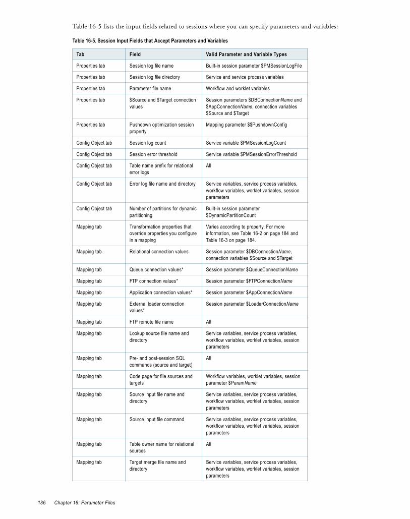
Table 16-5 lists the input fields related to sessions where you can specify parameters and variables:
Table 16-5. Session Input Fields that Accept Parameters and Variables
Tab Field Valid Parameter and Variable Types
Properties tab Session log file name Built-in session parameter $PMSessionLogFile
Properties tab Session log file directory Service and service process variables
Properties tab Parameter file name Workflow and worklet variables
Properties tab $Source and $Target connection values
Session parameters $DBConnectionName and $AppConnectionName, connection variables $Source and $Target
Properties tab Pushdown optimization session property
Mapping parameter $$PushdownConfig
Config Object tab Session log count Service variable $PMSessionLogCount
Config Object tab Session error threshold Service variable $PMSessionErrorThreshold
Config Object tab Table name prefix for relational error logs
All
Config Object tab Error log file name and directory Service variables, service process variables, workflow variables, worklet variables, session parameters
Config Object tab Number of partitions for dynamic partitioning
Built-in session parameter $DynamicPartitionCount
Mapping tab Transformation properties that override properties you configure in a mapping
Varies according to property. For more information, see Table 16-2 on page 184 and Table 16-3 on page 184.
Mapping tab Relational connection values Session parameter $DBConnectionName, connection variables $Source and $Target
Mapping tab Queue connection values* Session parameter $QueueConnectionName
Mapping tab FTP connection values* Session parameter $FTPConnectionName
Mapping tab Application connection values* Session parameter $AppConnectionName
Mapping tab External loader connection values*
Session parameter $LoaderConnectionName
Mapping tab FTP remote file name All
Mapping tab Lookup source file name and directory
Service variables, service process variables, workflow variables, worklet variables, session parameters
Mapping tab Pre- and post-session SQL commands (source and target)
All
Mapping tab Code page for file sources and targets
Workflow variables, worklet variables, session parameter $ParamName
Mapping tab Source input file name and directory
Service variables, service process variables, workflow variables, worklet variables, session parameters
Mapping tab Source input file command Service variables, service process variables, workflow variables, worklet variables, session parameters
Mapping tab Table owner name for relational sources
All
Mapping tab Target merge file name and directory
Service variables, service process variables, workflow variables, worklet variables, session parameters
186 Chapter 16: Parameter Files
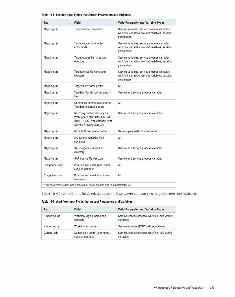
Table 16-6 lists the input fields related to workflows where you can specify parameters and variables:
Mapping tab Target merge command Service variables, service process variables, workflow variables, worklet variables, session parameters
Mapping tab Target header and footer commands
Service variables, service process variables, workflow variables, worklet variables, session parameters
Mapping tab Target output file name and directory
Service variables, service process variables, workflow variables, worklet variables, session parameters
Mapping tab Target reject file name and directory
Service variables, service process variables, workflow variables, worklet variables, session parameters
Mapping tab Target table name prefix All
Mapping tab Teradata FastExport temporary file
Service and service process variables
Mapping tab Control file content override for Teradata external loaders
All
Mapping tab Recovery cache directory for WebSphere MQ, JMS, SAP ALE IDoc, TIBCO, webMethods, Web Service Provider sources
Service and service process variables
Mapping tab Durable Subscription Name Session parameter $ParamName
Mapping tab MQ Source Qualifier filter condition
All
Mapping tab SAP stage file name and directory
Service and service process variables
Mapping tab SAP source file directory Service and service process variables
Components tab Post-session email (user name, subject, and text)
All
Components tab Post-session email attachment file name
All
* You can override connection attributes for this connection type in the parameter file.
Table 16-6. Workflow Input Fields that Accept Parameters and Variables
Tab Field Valid Parameter and Variable Types
Properties tab Workflow log file name and directory
Service, service process, workflow, and worklet variables
Properties tab Workflow log count Service variable $PMWorkflowLogCount
General tab Suspension email (user name, subject, and text)
Service, service process, workflow, and worklet variables
Table 16-5. Session Input Fields that Accept Parameters and Variables
Tab Field Valid Parameter and Variable Types
Where to Use Parameters and Variables 187

Table 16-7 lists the input fields related to connection objects in the Workflow Manager where you can specify parameters and variables:
Table 16-8 lists the input fields related to data profiling where you can specify parameters and variables:
Overriding Connection Attributes in the Parameter FileIf you use a session parameter to define a connection for a source or target, you can override the connection attributes in the parameter file. Use the $FTPConnectionName, $QueueConnectionName, $LoaderConnectionName, or $AppConnectionName session parameter.
When you define a connection in the parameter file, the Integration Service searches for specific, user-defined session parameters that define the connection attributes. For example, you create a Message Queue connection parameter called $QueueConnectionMyMQ and define it in the “[s_MySession]” section in the parameter file. The Integration Service searches this section of the parameter file for the “rows per message” parameter, $Param_QueueConnectionMyMQ_Rows_Per_Message.
When you install PowerCenter, the installation program creates a template file named ConnectionParam.prm that lists the connection attributes you can override for FTP, queue, loader, and application connections. The ConnectionParam.prm file is located in the following directory:
<PowerCenter Installation Directory>/server/bin
When you define a connection in the parameter file, copy the template for the appropriate connection type and paste it into the parameter file. Then supply the parameter values.
For example, to override connection attributes for an FTP connection in the parameter file, perform the following steps:
Table 16-7. Connection Object Input Fields that Accept Parameters and Variables
Connection Type Field Valid Parameter and Variable Types
Relational Database user name, password* Session parameter $ParamName
Relational: Source, Target, Lookup, Stored Procedure
Connection and transaction environment SQL
All
FTP User name, password* for host machine
Session parameter $ParamName
FTP Default remote directory All
Application Application user name, password*
Session parameter $ParamName
Application: Web Services Consumer
Endpoint URL Session parameter $ParamName, mapping parameters and variables
Application: HTTP Base URL Session parameter $ParamName
Application: JMS JMS Destination Session parameter $ParamName
Loader Database user name, password* Session parameter $ParamName
* Encrypt the password in the parameter file using the pmpasswd command line program with the CRYPT_DATA encryption type.
Table 16-8. Data Profiling Input Fields that Accept Parameters and Variables
Object Field Valid Parameter and Variable Types
Data Profile domain Data profiling domain value Service and service process variables
188 Chapter 16: Parameter Files

1. Configure the session or workflow to run with a parameter file.
2. In the session properties Mapping tab, select the source or target instance in the Connections node.
3. Click the Open button in the value field and configure the connection to use a session parameter. For example, use $FTPConnectionMyFTPConn for an FTP connection.
4. Open the ConnectionParam.prm template file in a text editor and scroll down to the section for the connection type whose attributes you want to override. For example, for an FTP connection, locate the “Connection Type: FTP” section:
Connection Type : FTP --------------------- ... Template ==================== $FTPConnection<VariableName>= $Param_FTPConnection<VariableName>_Remote_Filename= $Param_FTPConnection<VariableName>_Is_Staged= $Param_FTPConnection<VariableName>_Is_Transfer_Mode_ASCII=
5. Copy the template text for the connection attributes you want to override. For example, to override the “Remote File Name” and “Is Staged” attributes, copy the following lines:
$FTPConnection<VariableName>= $Param_FTPConnection<VariableName>_Remote_Filename= $Param_FTPConnection<VariableName>_Is_Staged=
6. Paste the text into the parameter file. Replace <VariableName> with the connection name, and supply the parameter values. For example:
[MyFolder.WF:wf_MyWorkflow.ST:s_MySession] $FTPConnectionMyFTPConn=FTP_Conn1 $Param_FTPConnectionMyFTPConn_Remote_Filename=ftp_src.txt $Param_FTPConnectionMyFTPConn_Is_Staged=YES
Note: The Integration Service interprets spaces or quotation marks before or after the equals sign as part of the parameter name or value.
If you do not define a value for an attribute, the Integration Service uses the value defined for the connection object.
Parameter File StructureA parameter file contains a list of parameters and variables with assigned values. You group parameters and variables in different sections of the parameter file. Each section is preceded by a heading that identifies the Integration Service, Integration Service process, workflow, worklet, or session to which you want to define parameters or variables. You define parameters and variables directly below the heading, entering each parameter or variable on a new line. You can list parameters and variables in any order within a section.
Enter the parameter or variable definition in the form name=value. For example, the following lines assign a value to service variable $PMSuccessEmailUser and session parameter $ParamTgtOverride:
[email protected]$ParamTgtOverride=UPDATE T_SALES SET DATE_SHIPPED = :TU.DATE_SHIPPED, TOTAL_SALES = :TU.TOTAL_SALES WHERE :TU.EMP_NAME = EMP_NAME and EMP_NAME = 'MIKE SMITH'
The Integration Service interprets all characters between the beginning of the line and the first equals sign as the parameter name and all characters between the first equals sign and the end of the line as the parameter value. Therefore, if you enter a space between the parameter name and the equals sign, the Integration Service interprets the space as part of the parameter name. If a line contains multiple equals signs, the Integration Service interprets all equals signs after the first one as part of the parameter value.
Parameter File Structure 189

Parameter File SectionsYou can define parameters and variables in any section in the parameter file. If you define a service or service process variable in a workflow, worklet, or session section, the variable applies to the service process that runs the task. Similarly, if you define a workflow variable in a session section, the value of the workflow variable applies only when the session runs.
The following table describes the parameter file headings that define each section in the parameter file and the scope of the parameters and variables that you define in each section:
Create each heading only once in the parameter file. If you specify the same heading more than once in a parameter file, the Integration Service uses the information in the section below the first heading and ignores the information in the sections below subsequent identical headings. For example, a parameter file contains the following identical headings:
[HET_TGTS.WF:wf_TCOMMIT1]$$platform=windows...[HET_TGTS.WF:wf_TCOMMIT1]$$platform=unix$DBConnection_ora=Ora2
In workflow wf_TCOMMIT1, the value for mapping parameter $$platform is “windows,” not “unix,” and session parameter $DBConnection_ora is not defined.
If you define the same parameter or variable in multiple sections in the parameter file, the parameter or variable with the smallest scope takes precedence over parameters or variables with larger scope. For example, a parameter file contains the following sections:
[HET_TGTS.WF:wf_TGTS_ASC_ORDR]$DBConnection_ora=Ora2[HET_TGTS.WF:wf_TGTS_ASC_ORDR.ST:s_TGTS_ASC_ORDR]$DBConnection_ora=Ora3
In session s_TGTS_ASC_ORDR, the value for session parameter $DBConnection_ora is “Ora3.” In all other sessions in the workflow, it is “Ora2.”
Heading Scope
[Global] All Integration Services, Integration Service processes, workflows, worklets, and sessions.
[Service:service name] The named Integration Service and workflows, worklets, and sessions that this service runs.
[Service:service name.ND:node name] The named Integration Service process and workflows, worklets, and sessions that this service process runs.
[folder name.WF:workflow name] The named workflow and all sessions within the workflow.
[folder name.WF:workflow name.WT:worklet name] The named worklet and all sessions within the worklet.
[folder name.WF:workflow name.WT:worklet name.WT:worklet name...]
The nested worklet and all sessions within the nested worklet.
[folder name.WF:workflow name.ST:session name]-or-[folder name.WF:workflow name.WT:worklet name.ST:session name]-or-[folder name.session name]-or-[session name]
The named session.
190 Chapter 16: Parameter Files

CommentsYou can include comments in parameter files. The Integration Service ignores lines that are not valid headings and do not contain an equals sign character (=). The following lines are examples of parameter file comments:
---------------------------------------Created 10/11/06 by JSmith.*** Update the parameters below this line when you run this workflow on Integration Service Int_01. ***; This is a valid comment because this line contains no equals sign.
Null ValuesYou can assign null values to parameters and variables in the parameter file. When you assign null values to parameters and variables, the Integration Service obtains the value from the following places, depending on the parameter or variable type:
♦ Service and service process variables. The Integration Service uses the value set in the Administration Console.
♦ Workflow and worklet variables. The Integration Service uses the value saved in the repository (if the variable is persistent), the user-specified default value, or the datatype default value.
♦ Session parameters. Session parameters do not have default values. If the Integration Service cannot find a value for a session parameter, it may fail the session, take an empty string as the default value, or fail to expand the parameter at run time. For example, the Integration Service fails a session where the session parameter $DBConnectionName is not defined.
♦ Mapping parameters and variables. The Integration Service uses the value saved in the repository (mapping variables only), the configured initial value, or the datatype default value.
To assign a null value, set the parameter or variable value to “<null>” or leave the value blank. For example, the following lines assign null values to service process variables $PMBadFileDir and $PMCacheDir:
$PMBadFileDir=<null>$PMCacheDir=
Sample Parameter FileThe following text is an excerpt from a parameter file that contains service variables for one Integration Service and parameters for four workflows:
----------------------------------------File created by RSmith 11/12/2005----------------------------------------[Service:IntSvs_01][email protected][email protected][HET_TGTS.WF:wf_TCOMMIT_INST_ALIAS]$$platform=unix[HET_TGTS.WF:wf_TGTS_ASC_ORDR.ST:s_TGTS_ASC_ORDR]$$platform=unix$DBConnection_ora=Ora2$ParamAscOrderOverride=UPDATE T_SALES SET CUST_NAME = :TU.CUST_NAME, DATE_SHIPPED = :TU.DATE_SHIPPED, TOTAL_SALES = :TU.TOTAL_SALES WHERE CUST_ID = :TU.CUST_ID[ORDERS.WF:wf_PARAM_FILE.WT:WL_PARAM_Lvl_1]$$DT_WL_lvl_1=02/01/2005 01:05:11$$Double_WL_lvl_1=2.2[ORDERS.WF:wf_PARAM_FILE.WT:WL_PARAM_Lvl_1.WT:NWL_PARAM_Lvl_2]$$DT_WL_lvl_2=03/01/2005 01:01:01$$Int_WL_lvl_2=3$$String_WL_lvl_2=ccccc
Parameter File Structure 191
Configuring the Parameter File Name and LocationWhen you start a workflow or session, use a parameter file to pass parameter and variable values to the Integration Service. You can specify the parameter file name and directory in the workflow or session properties or in the pmcmd command line. If the Integration Service uses operating system profiles, the operating system user specified in the operating system profile must have access to the parameter file.
The parameter file you use with pmcmd overrides the parameter file in the workflow or session properties. If you do not enter a parameter file name in the pmcmd command line, the Integration Service uses the parameter file you specify in the workflow properties for the workflow and all sessions in the workflow. If you do not enter a parameter file name in the pmcmd command line or the workflow properties, the Integration Service uses the parameter file you specify in the session properties.
Using a Parameter File with Workflows or SessionsYou can specify the parameter file name and directory in the workflow or session properties. Specify a workflow or worklet variable as the session parameter file name if you configure a workflow to run concurrently, and you want to use different parameter files for the sessions in each workflow run instance.
If you specify a parameter file for a workflow or session, and the Integration Service cannot locate the parameter file, it fails the workflow or session.
To enter a parameter file in the workflow properties:
1. Open a Workflow in the Workflow Manager.
2. Click Workflows > Edit.
The Edit Workflow dialog box appears.
3. Click the Properties tab.
4. Enter the parameter file location and name in the Parameter Filename field.
You can enter either a direct path or a service process variable. Use the appropriate delimiter for the Integration Service operating system. If you configured the PowerCenter environment for high availability, include the service process variable in the path
5. Click OK.
To enter a parameter file in the session properties:
1. Open a session in the Workflow Manager.
The Edit Tasks dialog box appears.
2. Click the Properties tab, and open the General Options settings.
3. Enter the parameter file location and name in the Parameter Filename field.
You can enter a direct path or a service process variable. Use the appropriate delimiter for the Integration Service operating system. If you configured the PowerCenter environment for high availability, include the service process variable in the path.
You can also enter a user-defined workflow or worklet variable. Enter a workflow or worklet variable to define the session parameter file name in the workflow parameter file.
4. Click OK.
Using Variables to Specify Session Parameter FilesYou can enter a workflow or worklet variable as the session parameter file name. Enter a workflow or worklet variable as the session parameter file name if you configure a workflow to run concurrently and you want to define different parameter and variable values for the sessions in each workflow run instance.
192 Chapter 16: Parameter Files

When you define a workflow parameter file and a session parameter file for a session within the workflow, the Integration Service uses the workflow parameter file, and ignores the session parameter file. To use a variable to define the session parameter file name, you must define the session parameter file name and set $PMMergeSessParamFile=TRUE in the workflow parameter file. The $PMMergeSessParamFile property causes the Integration Service to read both the session and workflow parameter files.
For example, you configured a workflow to run two concurrent instances that contains three sessions:
For the first and second workflow instances, you want the sessions to use the following session parameter files:
Create workflow variables to store the session parameter file names. For example, you create user-defined workflow variables $$s_1ParamFileName, $$s_2ParamFileName, and $$s_3ParamFileName. In the session properties for each session, set the parameter file name to a workflow variable:
In the workflow parameter file for each workflow instance, set each workflow variable to the correct session parameter file name, and set $PMMergeSessParamFile=TRUE.
If you use a variable as the session parameter file name, and you define the same parameter or variable in both the session and workflow parameter files, the Integration Service sets parameter and variable values according to the following rules:
♦ When a parameter or variable is defined in the same section of the workflow and session parameter files, the Integration Service uses the value in the workflow parameter file.
♦ When a parameter or variable is defined in both the session section of the session parameter file and the workflow section of the workflow parameter file, the Integration Service uses the value in the session parameter file.
Using a Parameter File with pmcmdUse parameter files with the pmcmd startworkflow or starttask commands. These commands allow you to specify the parameter file to use when you start a workflow or session.
The pmcmd -paramfile option defines which parameter file to use when a session or workflow runs. The -localparamfile option defines a parameter file on a local machine that you can reference when you do not have access to parameter files on the Integration Service machine.
The following command starts workflowA using the parameter file, myfile.txt:
pmcmd startworkflow -uv USERNAME -pv PASSWORD -s SALES:6258 -f east -w wSalesAvg -paramfile '\$PMRootDir/myfile.txt' workflowA
Session Session Parameter File Name (First workflow run instance)
Session Parameter File Name (Second workflow run instance)
s_1 s_1Inst1.txt s_1Inst2.txt
s_2 s_2Inst1.txt s_2Inst2.txt
s_3 s_3Inst1.txt s_3Inst2.txt
Session Session Parameter File Name in Session Properties
s_1 $$s_1ParamFileName
s_2 $$s_2ParamFileName
s_3 $$s_3ParamFileName
Configuring the Parameter File Name and Location 193
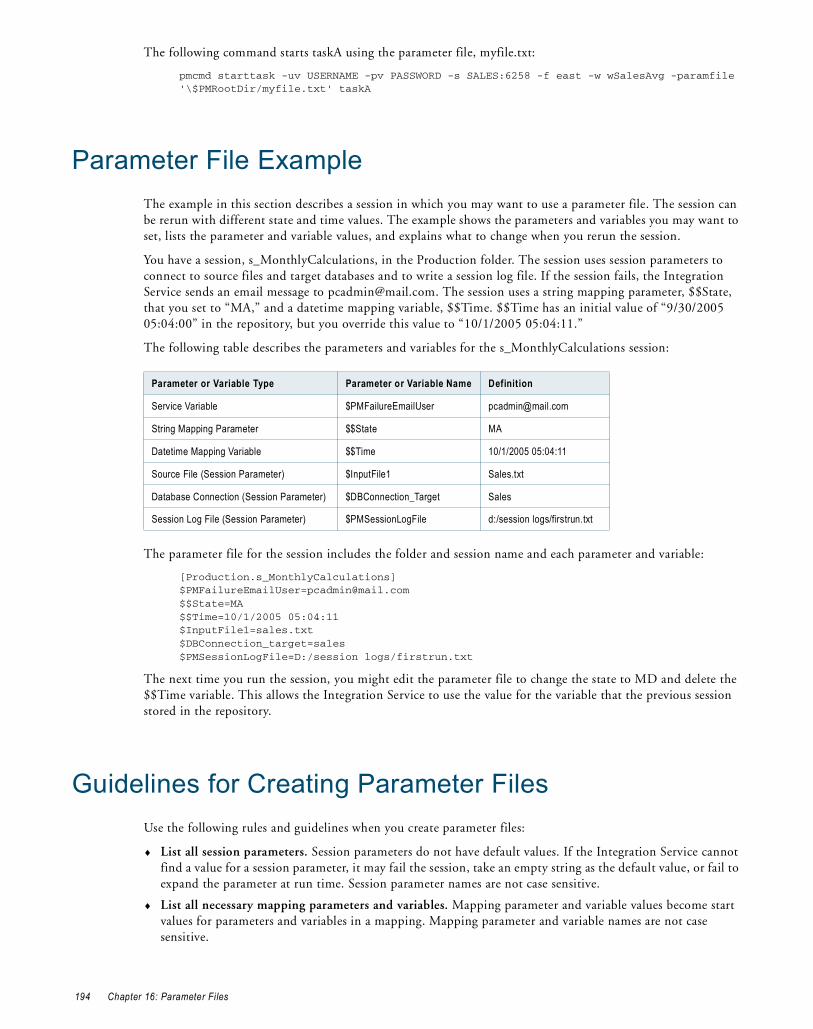
The following command starts taskA using the parameter file, myfile.txt:
pmcmd starttask -uv USERNAME -pv PASSWORD -s SALES:6258 -f east -w wSalesAvg -paramfile '\$PMRootDir/myfile.txt' taskA
Parameter File ExampleThe example in this section describes a session in which you may want to use a parameter file. The session can be rerun with different state and time values. The example shows the parameters and variables you may want to set, lists the parameter and variable values, and explains what to change when you rerun the session.
You have a session, s_MonthlyCalculations, in the Production folder. The session uses session parameters to connect to source files and target databases and to write a session log file. If the session fails, the Integration Service sends an email message to [email protected]. The session uses a string mapping parameter, $$State, that you set to “MA,” and a datetime mapping variable, $$Time. $$Time has an initial value of “9/30/2005 05:04:00” in the repository, but you override this value to “10/1/2005 05:04:11.”
The following table describes the parameters and variables for the s_MonthlyCalculations session:
The parameter file for the session includes the folder and session name and each parameter and variable:
[Production.s_MonthlyCalculations][email protected]$$State=MA$$Time=10/1/2005 05:04:11$InputFile1=sales.txt$DBConnection_target=sales$PMSessionLogFile=D:/session logs/firstrun.txt
The next time you run the session, you might edit the parameter file to change the state to MD and delete the $$Time variable. This allows the Integration Service to use the value for the variable that the previous session stored in the repository.
Guidelines for Creating Parameter FilesUse the following rules and guidelines when you create parameter files:
♦ List all session parameters. Session parameters do not have default values. If the Integration Service cannot find a value for a session parameter, it may fail the session, take an empty string as the default value, or fail to expand the parameter at run time. Session parameter names are not case sensitive.
♦ List all necessary mapping parameters and variables. Mapping parameter and variable values become start values for parameters and variables in a mapping. Mapping parameter and variable names are not case sensitive.
Parameter or Variable Type Parameter or Variable Name Definition
Service Variable $PMFailureEmailUser [email protected]
String Mapping Parameter $$State MA
Datetime Mapping Variable $$Time 10/1/2005 05:04:11
Source File (Session Parameter) $InputFile1 Sales.txt
Database Connection (Session Parameter) $DBConnection_Target Sales
Session Log File (Session Parameter) $PMSessionLogFile d:/session logs/firstrun.txt
194 Chapter 16: Parameter Files

♦ Enter folder names for non-unique session names. When a session name exists more than once in a repository, enter the folder name to indicate the location of the session.
♦ Precede parameters and variables in mapplets with the mapplet name. Use the following format:
mapplet_name.parameter_name=valuemapplet2_name.variable_name=value
♦ Use multiple parameter files. You assign parameter files to workflows, worklets, and sessions individually. You can specify the same parameter file for all of these tasks or create multiple parameter files.
♦ When defining parameter values, do not use unnecessary line breaks or spaces. The Integration Service interprets additional spaces as part of a parameter name or value.
♦ Use correct date formats for datetime values. Use the following date formats for datetime values:
− MM/DD/RR
− MM/DD/YYYY
− MM/DD/RR HH24:MI
− MM/DD/YYYY HH24:MI
− MM/DD/RR HH24:MI:SS
− MM/DD/YYYY HH24:MI:SS
− MM/DD/RR HH24:MI:SS.MS
− MM/DD/YYYY HH24:MI:SS.MS
− MM/DD/RR HH24:MI:SS.US
− MM/DD/YYYY HH24:MI:SS.US
− MM/DD/RR HH24:MI:SS.NS
− MM/DD/YYYY HH24:MI:SS.NS
You can use the following separators: dash (-), slash (/), backslash (\), colon (:), period (.), and space. The Integration Service ignores extra spaces. You cannot use one- or three-digit values for year or the “HH12” format for hour.
♦ Do not enclose parameter or variable values in quotes. The Integration Service interprets everything after the first equals sign as part of the value.
♦ Use a parameter or variable value of the proper length for the error log table name prefix. If you use a parameter or variable for the error log table name prefix, do not specify a prefix that exceeds 19 characters when naming Oracle, Sybase, or Teradata error log tables. The error table names can have up to 11 characters, and Oracle, Sybase, and Teradata databases have a maximum length of 30 characters for table names. The parameter or variable name can exceed 19 characters.
TroubleshootingI have a section in a parameter file for a session, but the Integration Service does not seem to read it.Make sure to enter folder and session names as they appear in the Workflow Manager. Also, use the appropriate prefix for all user-defined session parameters.
I am trying to use a source file parameter to specify a source file and location, but the Integration Service cannot find the source file.Make sure to clear the source file directory in the session properties. The Integration Service concatenates the source file directory with the source file name to locate the source file.
Also, make sure to enter a directory local to the Integration Service and to use the appropriate delimiter for the operating system.
Troubleshooting 195

I am trying to run a workflow with a parameter file and one of the sessions keeps failing.The session might contain a parameter that is not listed in the parameter file. The Integration Service uses the parameter file to start all sessions in the workflow. Check the session properties, and then verify that all session parameters are defined correctly in the parameter file.
I ran a workflow or session that uses a parameter file, and it failed. What parameter and variable values does the Integration Service use during the recovery run?For service variables, service process variables, session parameters, and mapping parameters, the Integration Service uses the values specified in the parameter file, if they exist. If values are not specified in the parameter file, then the Integration Service uses the value stored in the recovery storage file. For workflow, worklet, and mapping variables, the Integration Service always uses the value stored in the recovery storage file.
TipsUse a single parameter file to group parameter information for related sessions.When sessions are likely to use the same database connection or directory, you might want to include them in the same parameter file. When connections or directories change, you can update information for all sessions by editing one parameter file.
Use pmcmd and multiple parameter files for sessions with regular cycles.Sometimes you reuse session parameters in a cycle. For example, you might run a session against a sales database everyday, but run the same session against sales and marketing databases once a week. You can create separate parameter files for each session run. Instead of changing the parameter file in the session properties each time you run the weekly session, use pmcmd to specify the parameter file to use when you start the session.
Use reject file and session log parameters in conjunction with target file or target database connection parameters.When you use a target file or target database connection parameter with a session, you can keep track of reject files by using a reject file parameter. You can also use the session log parameter to write the session log to the target machine.
Use a resource to verify the session runs on a node that has access to the parameter file.In the Administration Console, you can define a file resource for each node that has access to the parameter file and configure the Integration Service to check resources. Then, edit the session that uses the parameter file and assign the resource. When you run the workflow, the Integration Service runs the session with the required resource on a node that has the resource available.
For more information about configuring the Integration Service to check resources, see the PowerCenter Administrator Guide.
You can override initial values of workflow variables for a session by defining them in a session section.If a workflow contains an Assignment task that changes the value of a workflow variable, the next session in the workflow uses the latest value of the variable as the initial value for the session. To override the initial value for the session, define a new value for the variable in the session section of the parameter file.
You can define parameters and variables using other parameters and variables.For example, in the parameter file, you can define session parameter $PMSessionLogFile using a service process variable as follows:
$PMSessionLogFile=$PMSessionLogDir/TestRun.txt
196 Chapter 16: Parameter Files

C H A P T E R 1 7
FastExport
This chapter includes the following topics:
♦ Overview, 197
♦ Step 1. Create a FastExport Connection, 198
♦ Step 2. Change the Reader, 200
♦ Step 3. Change the Source Connection, 200
♦ Step 4. Override the Control File (Optional), 200
♦ Rules and Guidelines, 201
OverviewFastExport is a utility that uses multiple Teradata sessions to quickly export large amounts of data from a Teradata database. You can create a PowerCenter session that uses FastExport to read Teradata sources.
To use FastExport, create a mapping with a Teradata source database. The mapping can include multiple source definitions from the same Teradata source database joined in a single Source Qualifier transformation. In the session, use FastExport reader instead of Relational reader. Use a FastExport connection to the Teradata tables you want to export in a session.
FastExport uses a control file that defines what to export. When a session starts, the Integration Service creates the control file from the FastExport connection attributes. If you create a SQL override for the Teradata tables, the Integration Service uses the SQL to generate the control file. You can override the control file for a session by defining a control file in the session properties.
The Integration Service writes FastExport messages in the session log and information about FastExport performance in the FastExport log. PowerCenter saves the FastExport log in the folder defined by the Temporary File Name session attribute. The default extension for the FastExport log is .log.
To use FastExport in a session, complete the following steps:
1. Create a FastExport connection in the Workflow Manager and configure the connection attributes.
2. Open the session and change the reader from Relational to Teradata FastExport.
3. Change the connection type and select a FastExport connection for the session.
4. Optionally, create a FastExport control file in a text editor and save it in the repository.
197

Step 1. Create a FastExport ConnectionCreate a FastExport connection in the Workflow Manager. If you edit a FastExport connection, all sessions using the connection use the updated connection.
To create a FastExport connection:
1. Click Connections > Application in the Workflow Manager.
The Connection Browser dialog box appears.
2. Click New.
3. Select a Teradata FastExport connection and click OK.
4. Enter a name for the FastExport connection.
5. Enter the database user name.
6. Enter the password for the database user name or click Use Parameter in Password to use the session parameter $ParamName for the database password.
If you enable Use Parameter in Password, define the password in the workflow or session parameter file and encrypt it using the pmpasswd CRYPT_DATA option.
7. Select the code page that FastExport uses to read Teradata sources.
FastExport uses the fexpcodepagemapfile.dat file to map the code page name to the Teradata character set that FastExport supports. Verify that the file includes the code page and that the assigned character set is enabled on the Teradata database. For more information, see “Verifying the Code Page Mapping File” on page 199.
8. Enter the FastExport attributes and click OK.
Table 17-1 describes the attributes that you configure for a Teradata FastExport connection:
Table 17-1. FastExport Connection Attributes
Attribute Default Value Description
TDPID n/a Teradata database ID.
Tenacity 4 Number of hours that FastExport tries to log on to the Teradata database. When FastExport tries to log on but the maximum number of Teradata sessions is already running, FastExport waits for the amount of time defined by the SLEEP option. After the SLEEP time, FastExport tries to log on to the Teradata Database again.FastExport repeats this process until it has either logged on for the required number of sessions or exceeded the TENACITY hours time period.
Max Sessions 1 Maximum number of FastExport sessions per FastExport job. Max Sessions must be between 1 and the total number of access module processes (AMPs) on your system.
Sleep 6 Number of minutes FastExport pauses before retrying a login. FastExport attempts a login until the login succeeds or the Tenacity hours elapse.
Block Size 64000 Maximum block size to use for the exported data.
Data Encryption Disabled Enables data encryption for FastExport. You can use data encryption with the version 8 Teradata client.
198 Chapter 17: FastExport

For more information about the connection attributes, see the Teradata documentation.
Verifying the Code Page Mapping FileWhen you create a FastExport connection, you select the PowerCenter code page that FastExport uses to read Teradata sources. FastExport uses the fexpcodepagemapfile.dat file to map the PowerCenter code page name to the Teradata character set that FastExport supports. For example, if you select “MS Windows Latin 1 (ANSI), superset of Latin1” as the connection code page, PowerCenter uses the code page named “MS1252” while Teradata uses the character set named “Latin1252_0A.”
The fexpcodepagemapfile.dat file maps the most appropriate Teradata character sets to PowerCenter code pages as specified in Teradata International Character Set Support. Teradata character sets must be enabled on the database before you can use them. By default, only the following character sets are enabled on a Teradata database:
♦ ASCII
♦ EBCDIC
♦ UTF8
♦ UTF16
If the PowerCenter code page you select in the FastExport connection does not exist in fexpcodepagemapfile.dat or if the assigned Teradata character set is not enabled on the database, the Integration Service fails the session.
The fexpcodepagemapfile.dat file is located in <PowerCenter installation directory>\server\bin. Verify that the file includes the PowerCenter code page you select in the FastExport connection and that the assigned character set is enabled on the Teradata database. You can use a text editor to assign additional PowerCenter code pages to Teradata character sets or to modify the existing mappings. Assign a PowerCenter code page to a Teradata character set by entering the names on a single line in the following format:
<PowerCenter_code_page> = <Teradata_character_set>.
For example, MS1252 = Latin1252_0A
Use the following rules and guidelines when you edit the file:
♦ To designate a comment, start a line with an exclamation point (!).
♦ A line cannot consist of blank spaces or tab characters only.
♦ If the file maps a single PowerCenter code page to multiple Teradata character sets, FastExport uses the character set that is assigned last in the file.
Note: Teradata does not distinguish between Big Endian and Lower Endian for UTF-16 encoding of Unicode. If you process UTF-16 characters, select the “UTF-16 encoding of Unicode (Platform Endian)” code page when creating the FastExport connection in the Workflow Manager.
Logtable Name FE_<source_table_name>
Restart log table name. The FastExport utility uses the information in the restart log table to restart jobs that halt because of a Teradata database or client system failure. Each FastExport job should use a separate logtable. If you specify a table that does not exist, the FastExport utility creates the table and uses it as the restart log.PowerCenter does not support restarting FastExport, but if you stage the output, you can restart FastExport manually.
Executable Name fexp Teradata command used to read the source data. Use the default value.
Database Name n/a The name of the Teradata database you want to connect to. The Integration Service generates the SQL statement using the database name as a prefix to the table name.
Table 17-1. FastExport Connection Attributes
Attribute Default Value Description
Step 1. Create a FastExport Connection 199

Step 2. Change the ReaderThe default reader for Teradata is relational. To use FastExport, change the reader to Teradata FastExport.
Step 3. Change the Source ConnectionTo use FastExport in the session, change the Teradata source connection to a Teradata FastExport connection. You can override some session attributes.
Table 17-2 describes the session attributes you can change for FastExport:
Step 4. Override the Control File (Optional)By default, the Integration Service generates a FastExport control file based on session and connection properties when you run a session with FastExport. The Integration Service saves the control file it generates in the temporary file directory and overwrites it the next time you run the session.
You can override the control file that the Integration Service generates. When you override the control file, the Workflow Designer saves the control file to the repository. The Integration Service uses the saved control file when you run the session.
Each FastExport statement must meet the following criteria:
♦ Begin on a new line.
♦ Start with a period (.).
♦ End with a semicolon (;).
For more information about the control file, see the Teradata documentation.
Table 17-2. Fast Export Session Attributes
Attribute Default Value Precision
Is Staged Disabled If enabled, FastExport writes data to a stage file. Otherwise, FastExport writes data to a named pipe.
Fractional seconds precision
0 The precision for fractional seconds following the decimal point in a timestamp. You can enter 0 to 6. For example, a timestamp with a precision of 6 is 'hh:mi:ss.ss.ss.ss.' The fractional seconds precision must match the setting in the Teradata database.
Temporary File $PMTempDir\ PowerCenter uses the temporary file name to generate the names for the log file, control file, and the staged output file. Enter a complete path for the file.
Control File Override Blank The control file text. Use this attribute to override the control file the Integration Service creates for a session.
200 Chapter 17: FastExport

Table 17-3 describes the control file statements you can use with PowerCenter:
To override the control file:
1. Create a control file in a text editor.
2. Copy the control file text to the clipboard.
3. Paste the control file text into the Control File Override field.
The Workflow Manager does not validate the control file syntax. Teradata verifies the control file syntax when you run a session. If the control file is invalid, the session fails.
Tip: You can change the control file to read-only to use the control file for each session. The Integration Service does not overwrite the read-only file.
Rules and GuidelinesUse the following rules and guidelines when you use FastExport with PowerCenter:
♦ When you use an SQL override for Teradata, PowerCenter uses it to create the FastExport control file. If you do not use an SQL override, PowerCenter generates a control file based on the connected ports in the source qualifier.
♦ FastExport supports a maximum export file size of 2 GB on a UNIX MP-RAS operating system. Other operating systems have no file size limitation.
♦ You cannot concatenate exported data files.
♦ The session fails if you use a pre-session SQL command and FastExport.
Table 17-3. FastExport Control File Statements
Control File Statement Description
.LOGTABLE utillog; The restart logtable name.
LOGON tdpz/user,pswd; The database login string, including the database, user name, and password.
BEGIN EXPORT The first export command.
.SESSIONS 20; The number of Teradata sessions.
.EXPORT OUTFILE ddname2; The destination file for the exported data.
SELECT EmpNo, Hours FROM charges The SQL statements to select data.
WHERE Proj_ID = 20
ORDER BY EmpNo ;
.END EXPORT ; Indicates the end of an export task and initiates the export process.
LOGOFF ; Disconnect from the database.
Rules and Guidelines 201

202 Chapter 17: FastExport

C H A P T E R 1 8
External Loading
This chapter includes the following topics:
♦ Overview, 203
♦ External Loader Behavior, 204
♦ Loading to IBM DB2, 205
♦ Loading to Oracle, 210
♦ Loading to Sybase IQ, 212
♦ Loading to Teradata, 214
♦ Configuring External Loading in a Session, 224
♦ Troubleshooting, 226
OverviewYou can configure a session to use IBM DB2, Oracle, Sybase IQ, and Teradata external loaders to load session target files into their respective databases. External loaders can increase session performance by loading information directly from a file or pipe rather than running the SQL commands to insert the same data into the database.
Use multiple external loaders within one session. For example, if a mapping contains two targets, you can create a session that uses an Oracle external loader connection and a Sybase IQ external loader connection.
For information about creating external loader connections, see the PowerCenter Workflow Basics Guide.
Before You BeginBefore you run external loaders, complete the following tasks:
♦ Disable constraints. You disable constraints built into the tables receiving the data before performing the load. For information about disabling constraints, see the database documentation.
♦ Turn off or disable database logging. To preserve high performance, you can increase commit intervals and turn off database logging. However, to perform database recovery on failed sessions, you must have database logging turned on.
♦ Configure code pages. IBM DB2, Oracle, Sybase IQ, and Teradata database servers must use the same code page as the target flat file code page. The Integration Service creates the control files and target flat files using the target flat file code page. If you use a code page other than 7-bit ASCII for the target flat file, run the Integration Service in Unicode data movement mode.
203

♦ Configure the external loader connection as a resource. If the Integration Service is configured to run on a grid, configure the external loader connection as a resource on the node where the external loader is available. For more information, see the PowerCenter Administrator Guide.
External Loader BehaviorWhen you run a session that uses an external loader, the Integration Service creates a control file and a target flat file. The control file contains information such as data format and loading instructions for the external loader. The control file has an extension of .ctl. You can view the control file and the target flat file in the target file directory.
When you run a session, the Integration Service deletes and recreates the target file. The external loader uses the control file to load session output to the database. The Integration Service processes datetime data before loading to the database in the following ways:
♦ If the session is configured to trim subseconds, the Integration Service processes datetime data with a precision of 19.
♦ If the session is not configured to trim subseconds, the Integration Service processes datetime data based on the precision specified in the target flat file. Precision ranges from 19 to 29. Subseconds are trimmed according to the precision specified.
♦ If the precision specified in the target file is greater than that specified for the database, the Integration Service limits the precision to the maximum precision specified for the database.
The Integration Service waits for all external loading to complete before it performs post-session commands, runs external procedures, and sends post-session email.
The Integration Service writes external loader initialization and completion messages in the session log. For more information about the external loader performance, check the external loader log. The loader saves the log in the same directory as the target flat files. The default extension for external loader logs is .ldrlog.
The behavior of the external loader depends on how you choose to load the data. You can load data to a named pipe or to a flat file.
Loading Data to a Named PipeThe external loader starts to load data to the database as soon as the data appears in the pipe. The loader deletes the named pipe as soon as it completes the load.
On UNIX, the Integration Service writes to a named pipe that is named after the configured target file name.
On Windows, the Integration Service writes data to a named pipe using the specified format:
\\.\pipe\<pipe name>
The pipe name is the same as the configured target file name.
Staging Data to a Flat FileWhen you stage data to a flat file on Windows or UNIX, the Integration Service writes data to a flat file, which is named after the configured target file name. The external loader starts loading data to the target database after the Integration Service writes all the data to the target flat file. The external loader does not delete the target flat file after loading it to the database. Make sure the target file directory can accommodate the size of the target flat file.
Note: The Integration Service rounds numerical values based on the scale of the port when staging data to a flat file. It does not round results when you use an external loader that loads the data to a named pipe or if you configure the target for a normal load.
204 Chapter 18: External Loading

If a session aborts or fails before the Integration Service writes all the data to the flat file target, the external loader does not start. If a session aborts or fails after the Integration Service writes all the data to the flat file target, the external loader completes loading data to the target database before the external loader exits.
Partitioning Sessions with External LoadersWhen you configure multiple partitions in a session using a flat file target, the Integration Service creates a separate flat file for each partition. Some external loaders cannot load data from multiple files. When you use an external loader in a session with multiple partitions, you must configure the target partition type according to the external loader you use.
When you use an external loader that can load data from multiple files, you can choose any partition type available for a flat file target. You also choose an external loader connection for each partition. The Integration Service creates an output file for each partition, and the external loader loads the output from each target file to the database. Use any partition type for the target when you use the following loaders:
♦ Oracle, with parallel load enabled
♦ Teradata Tpump
♦ Teradata Warehouse Builder
If you use a loader that cannot load from multiple files, use round-robin partitioning to route the data to a single target file. You choose an external loader connection for each partition. However, the Integration Service uses the loader connection for the first partition. The Integration Service creates a single output file, and the external loader loads the output from the target file to the database. If you choose any other partition type for the target, the Integration Service fails the session. Use round-robin partition type for the target when you use the following loaders:
♦ IBM DB2 EE
♦ IBM DB2 EEE Autoloader
♦ Oracle, with parallel load disabled
♦ Sybase IQ
♦ Teradata MultiLoad
♦ Teradata Fastload
Loading to IBM DB2When you load to IBM DB2 targets, use the IBM DB2 EE or IBM DB2 EEE external loader. Both external loaders perform insert and replace operations on targets. They can also restart or terminate load operations. Both external loaders can partition data and load the partitioned data simultaneously to the corresponding database partitions.
IBM DB2 EE External LoaderUse the IBM DB2 EE external loader to load into one of the following databases:
♦ IBM DB2 EE version 8.x
♦ IBM DB2 EEE version 8.x
♦ IBM DB2 version 9.x
The IBM DB2 EE external loader invokes one of the following executables located in the Integration Service installation directory:
♦ db2load. Use for the IBM DB2 client earlier than version 9.5.
♦ db2load95. Use for the IBM DB2 client version 9.5.
Loading to IBM DB2 205

When you create the external loader connection, specify the executable file name depending on the IBM DB2 client version installed on the machine where the Integration Service process runs.
The IBM DB2 EE external loader can load data to an IBM DB2 server on a machine that is remote from the Integration Service.
Processing LOB DataThe IBM DB2 EE external loader cannot load LOB data, such as Blob, Clob, or Dbclob data. When you run a session that uses the IBM DB2 EE external loader and the source contains LOB data, the external loader successfully loads the remaining data to the target depending on the following mapping configurations:
♦ LOB ports are unconnected. The external loader successfully loads all remaining data to the target.
♦ LOB ports are connected. When loading to a database version 8.x, the external loader loads the LOB data as NULL and correctly loads the remaining data. When loading to a database version 9.x, the external loader does not load any data. It logs rejected rows in the external loader log.
IBM DB2 EEE External LoaderUse the IBM DB2 EEE external loader to load into an IBM DB2 EEE version 8.x database. The IBM DB2 EEE external loader invokes the IBM DB2 Autoloader program to load data. The Autoloader program uses the db2atld executable. The IBM DB2 EEE loader requires that the IBM DB2 server be on the same machine hosting the Integration Service.
Note: If the IBM DB2 EEE server is on a machine that is remote from the Integration Service, use the IBM DB2 EE external loader or connect to the IBM DB2 EEE database using a relational database connection. Use database partitioning for the IBM DB2 target. When you use database partitioning, the Integration Service queries the IBM DB2 system for table partition information and loads partitioned data to the corresponding nodes in the target database. For more information about database partitioning, see “Database Partitioning Partition Type” on page 38.
Rules and GuidelinesUse the following rules and guidelines when you use external loaders to load to IBM DB2:
♦ The IBM DB2 external loaders load from a delimited flat file. Verify that the target table columns are wide enough to store all of the data.
♦ For a connection that uses IBM DB2 client authentication, enter the PmNullUser user name and PmNullPasswd when you create the external loader connection. PowerCenter uses IBM DB2 client authentication when the connection user name is PmNullUser and the connection is to an IBM DB2 database.
♦ For a session with multiple partitions, use the round-robin partition type to route data to a single target file. For more information about partitioning sessions with external loaders, see “Partitioning Sessions with External Loaders” on page 205.
♦ If you configure multiple targets in the same pipeline to use IBM DB2 external loaders, each loader must load to a different tablespace on the target database. For more information about selecting external loaders, see “Configuring External Loading in a Session” on page 224.
♦ You must have the correct authority levels and privileges to load data to the database tables. For more information, see “Configuring Authorities, Privileges, and Permissions” on page 207.
Setting Operation ModesIBM DB2 operation modes specify the type of load the external loader runs. You can configure the IBM DB2 EE or IBM DB2 EEE external loader to run in one of the following operation modes:
♦ Insert. Adds loaded data to the table without changing existing table data.
206 Chapter 18: External Loading

♦ Replace. Deletes all existing data from the table, and inserts the loaded data. The table and index definitions do not change.
♦ Restart. Restarts a previously interrupted load operation.
♦ Terminate. Terminates a previously interrupted load operation and rolls back the operation to the starting point, even if consistency points were passed. The tablespaces return to normal state, and the external loader makes all table objects consistent.
Configuring Authorities, Privileges, and PermissionsIBM DB2 privileges allow you to create or access database resources. Authority levels allow you to group privileges and perform higher-level database manager maintenance and utility operations. Together, these act to control access to the database manager and its database objects. You can access objects for which you have the required privilege or authority.
To load data into a table, you must have one of the following authorities:
♦ SYSADM authority
♦ DBADM authority
♦ LOAD authority on the database and one of the following privileges:
− INSERT privilege on the table when the load utility is invoked in insert, terminate, or restart mode.
− INSERT and DELETE privilege on the table when the load utility is invoked in replace, terminate, or restart mode.
In addition, you must have proper read access and read/write permissions:
♦ The database instance owner must have read access to the external loader input files.
♦ If you run IBM DB2 as a service on Windows, you must configure the service start account with a user account that has read/write permissions to use LAN resources, including drives, directories, and files.
♦ If you load to IBM DB2 EEE, the database instance owner must have write access to the load dump file and the load temporary file.
For more information, see the IBM DB2 database documentation.
Configuring IBM DB2 EE External Loader AttributesThe IBM DB2 EE external loader creates a single log or multiple logs depending on the following databases that you are loading to:
♦ IBM DB2 EE version 8.x or non-partitioned IBM DB2 version 9.x. The external loader creates a single external loader log with the extension .ldrlog in the same directory as the target flat files.
♦ IBM DB2 EEE version 8.x or partitioned IBM DB2 version 9.x. The external loader creates multiple external loader logs in the same directory as the target flat files. The loader logs have the following extensions:
− ldrlog.load.number. Created by the Load Agent external loader process. The Load Agent creates two log files.
− ldrlog.part.partition_number. Created by the Partitioning Agent external loader process. The Partitioning Agent can create multiple log files depending on the number of partitions in the target table.
− ldrlog.prep.partition_number. Created by the Pre-partitioning Agent external loader process. The Pre-partitioning Agent can create multiple log files depending on the number of partitions in the target table.
− ldrlog. Created by the IBM DB2 EE external loader.
Loading to IBM DB2 207

The following table describes attributes for IBM DB2 EE external loader connections:
Loading Blank Spaces using the IBM DB2 EE External LoaderIf you need to load blank spaces through the IBM DB2 EE external loader, you must configure the session. In staged mode, configure the flat file to use double optional quotes. In non-staged mode, add the following line to the control file:
MODIFIEDBY = keepblanks
Configure the control file to be read-only.
IBM DB2 EE External Loader Return CodesThe IBM DB2 EE external loader indicates the success or failure of a load operation with a return code. The Integration Service writes the external loader return code to the session log. Return code (0) indicates that the load operation succeeded. The Integration Service writes the following message to the session log if the external loader successfully completes the load operation:
WRT_8029 External loader process <external loader name> exited successfully.
Any other return code indicates that the load operation failed. The Integration Service writes the following error message to the session log:
WRT_8047 Error: External loader process <external loader name> exited with error <return code>.
The following table describes the return codes for the IBM DB2 EE external loader:
Attributes Default Value Description
Opmode Insert IBM DB2 external loader operation mode. Select one of the following operation modes:- Insert- Replace- Restart- TerminateFor more information about IBM DB2 operation modes, see “Setting Operation Modes” on page 206.
External Loader Executable
db2load Name of the IBM DB2 EE external loader executable file. Enter one of the following file names depending on the IBM DB2 client version installed on the machine where the Integration Service process runs:- db2load. Use for the IBM DB2 client earlier than version 9.5.- db2load95. Use for the IBM DB2 client version 9.5.
DB2 Server Location Remote Location of the IBM DB2 database server relative to the Integration Service. Select Local if the database server resides on the machine hosting the Integration Service. Select Remote if the database server resides on another machine.
Is Staged Disabled Method of loading data. Select Is Staged to load data to a flat file staging area before loading to the database. By default, the data is loaded to the database using a named pipe. For more information, see “External Loader Behavior” on page 204.
Recoverable Enabled Sets tablespaces in backup pending state if forward recovery is enabled. If you disable forward recovery, the IBM DB2 tablespace will not set to backup pending state. If the IBM DB2 tablespace is in backup pending state, you must fully back up the database before you perform any other operation on the tablespace.
Code Description
0 External loader operation completed successfully.
1 External loader cannot locate the control file.
208 Chapter 18: External Loading

Configuring IBM DB2 EEE External Loader AttributesYou can configure the IBM DB2 EEE external loader to use different loading modes when loading to the database. Loading modes determine how the IBM DB2 EEE external loader loads data across partitions in the database. You can configure the IBM DB2 EEE external loader to use the following loading modes:
♦ Split and load. Partitions the data and loads it simultaneously using the corresponding database partitions.
♦ Split only. Partitions the data and writes the output to files in the specified split file directory.
♦ Load only. Does not partition the data. It loads data in existing split files using the corresponding database partitions.
♦ Analyze. Generates an optimal partitioning map with even distribution across all database partitions. If you run the external loader in split and load mode after you run it in analyze mode, the external loader uses the optimal partitioning map to partition the data.
For more information about IBM DB2 loading modes, see the IBM DB2 database documentation.
The IBM DB2 EEE external loader creates multiple logs based on the number of database partitions it loads to. For each partition, the external loader appends a number corresponding to the partition number to the external loader log file name. The IBM DB2 EEE external loader log file format is file_name.ldrlog.partition_number.
The Integration Service does not archive or overwrite IBM DB2 EEE external loader logs. If an external loader log of the same name exists when the external loader runs, the external loader appends new external loader log messages to the end of the existing external loader log file. You must manually archive or delete the external loader log files. For more information about log files generated by DB2 Autoload, see the IBM DB2 documentation.
For information about IBM DB2 EEE external loader return codes, see the IBM DB2 documentation.
The following table describes attributes for IBM DB2 EEE external loader connections:
2 External loader could not open the external loader log file.
3 External loader could not access the control file because the control file is locked by another process.
4 IBM DB2 database returned an error.
Attribute Default Value Description
Opmode Insert IBM DB2 external loader operation mode. Select one of the following operation modes:- Insert- Replace- Restart- TerminateFor more information about IBM DB2 operation modes, see “Setting Operation Modes” on page 206.
External Loader Executable
db2atld Name of the IBM DB2 EEE external loader executable file.
Split File Location n/a Location of the split files. The external loader creates split files if you configure SPLIT_ONLY loading mode.
Output Nodes n/a Database partitions on which the load operation is to be performed.
Split Nodes n/a Database partitions that determine how to split the data. If you do not specify this attribute, the external loader determines an optimal splitting method.
Code Description
Loading to IBM DB2 209

Loading to OracleWhen you load to Oracle targets, use the Oracle SQL Loader to perform insert, update, and delete operations on targets.
The Oracle external loader creates a reject file for data rejected by the database. The reject file has an extension of .ldrreject. The loader saves the reject file in the target files directory.
Rules and GuidelinesUse the following rules and guidelines when you use external loaders to load to Oracle:
♦ If you select an Oracle external loader, the default external loader executable name is sqlload. This is accurate for most UNIX platforms, but if you use Windows, check the Oracle documentation to find the name of the external loader executable.
Mode Split and load
Loading mode the external loader uses to load the data. Select one of the following loading modes:- Split and load- Split only- Load only- Analyze
Max Num Splitters 25 Maximum number of splitter processes.
Force No Forces the external loader operation to continue even if it determines at startup time that some target partitions or tablespaces are offline.
Status Interval 100 Number of megabytes of data the external loader loads before writing a progress message to the external loader log. Specify a value between 1 and 4,000 MB.
Ports 6000-6063 Range of TCP ports the external loader uses to create sockets for internal communications with the IBM DB2 server.
Check Level Nocheck Checks for record truncation during input or output.
Map File Input n/a Name of the file that specifies the partitioning map. To use a customized partitioning map, specify this attribute. Generate a customized partitioning map when you run the external loader in Analyze loading mode.
Map File Output n/a Name of the partitioning map when you run the external loader in Analyze loading mode. You must specify this attribute if you want to run the external loader in Analyze loading mode.
Trace 0 Number of rows the external loader traces when you need to review a dump of the data conversion process and output of hashing values.
Is Staged Disabled Method of loading data. Select Is Staged to load data to a flat file staging area before loading to the database. Otherwise, the data is loaded to the database using a named pipe. For more information, see “External Loader Behavior” on page 204.
Date Format mm/dd/yyyy Date format. Must match the date format you define in the target definition. IBM DB2 supports the following date formats:- MM/DD/YYYY- YYYY-MM-DD- DD.MM.YYYY- YYYY-MM-DD
Attribute Default Value Description
210 Chapter 18: External Loading

♦ For a connection that uses Oracle OS Authentication, enter the PmNullUser user name and PmNullPasswd when you create the external loader connection. PowerCenter uses Oracle OS Authentication when the connection user name is PmNullUser and the connection is to an Oracle database.
♦ The target flat file for an Oracle external loader can be fixed-width or delimited.
♦ For optimal performance when writing to a partitioned target, select Direct Path. For more information, see the Oracle documentation.
♦ If you configure a session to write subsecond data to a Timestamp column in an Oracle 10.x or Oracle 11.x target, the Integration Service writes subsecond data up to microseconds by default. To ensure greater precision, edit the control file and change the Timestamp precision. For example, specify TIMESTAMP(9) to process nanoseconds.
♦ For optimal performance, use the following guidelines to determine settings for partitioned and non-partitioned targets:
Loading Multibyte Data to OracleWhen you load multibyte data to Oracle, data precision is measured in bytes for fixed-width files and in characters for delimited files. Make sure the target table columns are wide enough to store all the data.
Oracle supports character-oriented datatypes, such as Nchar, where the precision is measured in characters. If you use the Nchar datatype, multiply the maximum number of characters by K, where K is the maximum number of bytes a character contains in the selected target code page. This ensures that the Integration Service does not truncate data before loading the target file.
Configuring Oracle External Loader AttributesThe following table describes the attributes for Oracle external loader connections:
Target Load Method Parallel Load Load Mode
Partitioned Direct Path enable Append
Partitioned Conventional Path enable n/a
Non-partitioned n/a disable* n/a
* If you disable parallel load, you must choose round-robin partitioning to route data to a single target file.
Attribute Default Value Description
Error Limit 1 Number of errors to allow before the external loader stops the load operation.
Load Mode Append Loading mode the external loader uses to load data. Select one of the following loading modes:- Append- Insert- Replace- Truncate
Load Method Use Conventional Path
Method the external loader uses to load data. Select one of the following load methods:- Use Conventional Path.- Use Direct Path (Recoverable). - Use Direct Path (Unrecoverable).
Enable Parallel Load
Enable Parallel Load
Determines whether the Oracle external loader loads data in parallel to a partitioned Oracle target table. - Enable Parallel Load to load to partitioned targets.- Do Not Enable Parallel Load to load to non-partitioned
targets.
Loading to Oracle 211
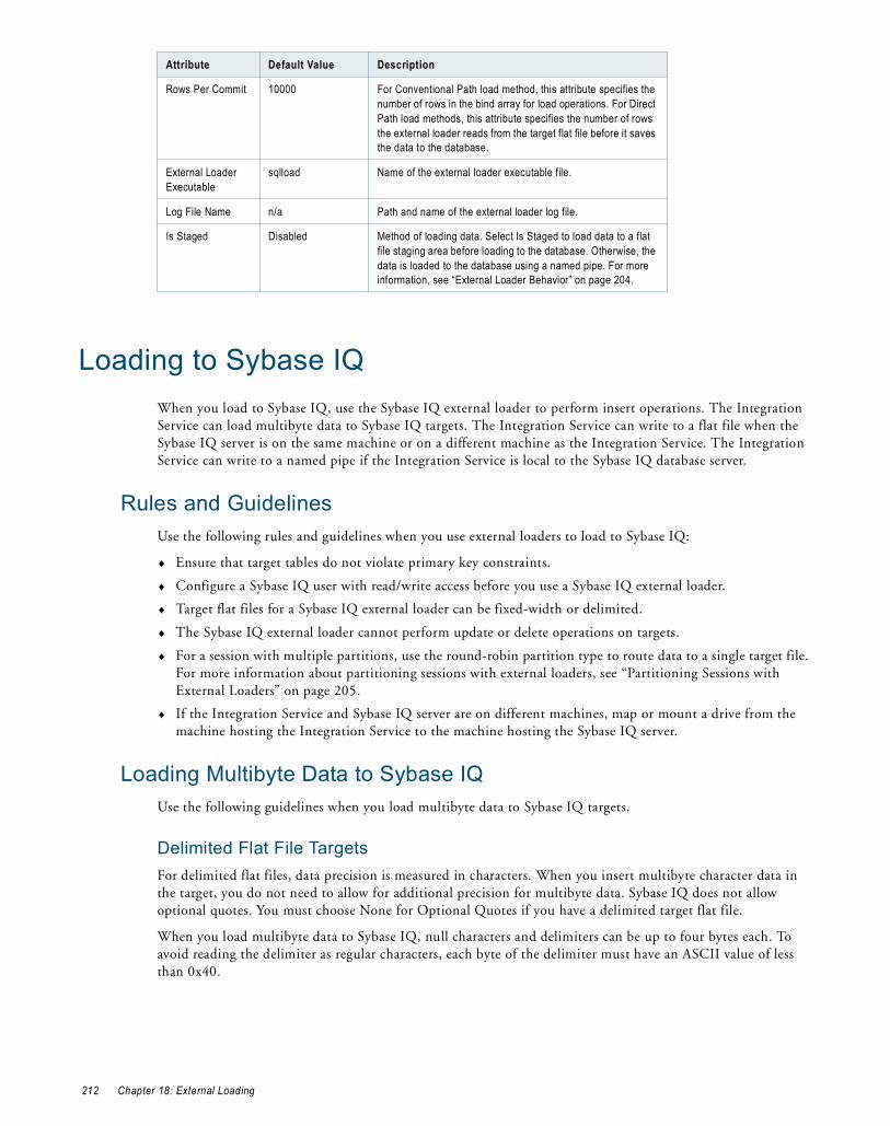
Loading to Sybase IQWhen you load to Sybase IQ, use the Sybase IQ external loader to perform insert operations. The Integration Service can load multibyte data to Sybase IQ targets. The Integration Service can write to a flat file when the Sybase IQ server is on the same machine or on a different machine as the Integration Service. The Integration Service can write to a named pipe if the Integration Service is local to the Sybase IQ database server.
Rules and GuidelinesUse the following rules and guidelines when you use external loaders to load to Sybase IQ:
♦ Ensure that target tables do not violate primary key constraints.
♦ Configure a Sybase IQ user with read/write access before you use a Sybase IQ external loader.
♦ Target flat files for a Sybase IQ external loader can be fixed-width or delimited.
♦ The Sybase IQ external loader cannot perform update or delete operations on targets.
♦ For a session with multiple partitions, use the round-robin partition type to route data to a single target file. For more information about partitioning sessions with external loaders, see “Partitioning Sessions with External Loaders” on page 205.
♦ If the Integration Service and Sybase IQ server are on different machines, map or mount a drive from the machine hosting the Integration Service to the machine hosting the Sybase IQ server.
Loading Multibyte Data to Sybase IQUse the following guidelines when you load multibyte data to Sybase IQ targets.
Delimited Flat File TargetsFor delimited flat files, data precision is measured in characters. When you insert multibyte character data in the target, you do not need to allow for additional precision for multibyte data. Sybase IQ does not allow optional quotes. You must choose None for Optional Quotes if you have a delimited target flat file.
When you load multibyte data to Sybase IQ, null characters and delimiters can be up to four bytes each. To avoid reading the delimiter as regular characters, each byte of the delimiter must have an ASCII value of less than 0x40.
Rows Per Commit 10000 For Conventional Path load method, this attribute specifies the number of rows in the bind array for load operations. For Direct Path load methods, this attribute specifies the number of rows the external loader reads from the target flat file before it saves the data to the database.
External Loader Executable
sqlload Name of the external loader executable file.
Log File Name n/a Path and name of the external loader log file.
Is Staged Disabled Method of loading data. Select Is Staged to load data to a flat file staging area before loading to the database. Otherwise, the data is loaded to the database using a named pipe. For more information, see “External Loader Behavior” on page 204.
Attribute Default Value Description
212 Chapter 18: External Loading

Fixed-Width Flat File TargetsFor fixed-width flat files, data precision is measured in bytes, not characters. When you load multibyte data into a fixed-width flat file target, configure the precision to accommodate the multibyte data. The Integration Service writes the row to the reject file if the precision is not large enough to accommodate the multibyte data.
Configuring Sybase IQ External Loader AttributesUse the following rules and guidelines when you enter attributes for the Sybase IQ external loader connection:
♦ The connect string must contain the following attributes:
uid=user ID; pwd=password; eng=Sybase IQ database server name; links=tcpip (host=host name; port=port number)
For example, you might use the following connect string:
uid=qasrvr65;pwd=qasrvr65;eng=SUNQA2SybaseIQ_1243;links=tcpip(host=sunqa2)
♦ The session might fail if you use quotes in the connect string.
The following table describes the attributes for Sybase IQ external loader connections:
Attribute Default Value Description
Block Factor 10000 Number of records per block in the target Sybase table. The external loader applies the Block Factor attribute to load operations for fixed-width flat file targets only.
Block Size 50000 Size of blocks used in Sybase database operations. The external loader applies the Block Size attribute to load operations for delimited flat file targets only.
Checkpoint Enabled If enabled, the Sybase IQ database issues a checkpoint after successfully loading the table. If disabled, the database issues no checkpoints.
Notify Interval 1000 Number of rows the Sybase IQ external loader loads before it writes a status message to the external loader log.
Server Datafile Directory n/a The Sybase IQ server location that is accessible from the machine that hosts the Integration Service. If you specify the target file location, the Sybase IQ server may fail to access the file.Specify this attribute relative to the database server installation directory.If the directory is in a Windows system, use a backslash (\) in the directory path:D:\mydirectory\inputfile.outIf the directory is in a UNIX system, use a forward slash (/) in the directory path:/mydirectory/inputfile.outEnter the directory path using the syntax for the machine hosting the database server installation. For example, if the Integration Service is on a Windows machine and the Sybase IQ server is on a UNIX machine, use UNIX syntax.
Loading to Sybase IQ 213

Loading to TeradataWhen you load to Teradata targets, use one of the following external loaders:
♦ Multiload. Performs insert, update, delete, and upsert operations for large volume incremental loads. Use this loader when you run a session with a single partition. Multiload acquires table level locks, making it appropriate for offline loading. For more information about configuring the Multiload external loader connection object, see “Configuring Teradata MultiLoad External Loader Attributes” on page 216.
♦ TPump. Performs insert, update, delete, and upsert operations for relatively low volume updates. Use this loader when you run a session with multiple partitions. TPump acquires row-hash locks on the table, allowing other users to access the table as TPump loads to it. For more information about configuring the Tpump external loader connection object, see “Configuring Teradata TPump External Loader Attributes” on page 218.
♦ FastLoad. Performs insert operations for high volume initial loads, or for high volume truncate and reload operations. Use this loader when you run a session with a single partition. Use this loader on empty tables with no secondary indexes. For more information about configuring the FastLoad external loader connection object, see “Configuring Teradata FastLoad External Loader Attributes” on page 220.
♦ Warehouse Builder. Performs insert, update, upsert, and delete operations on targets. Use this loader when you run a session with multiple partitions. You can achieve the functionality of the other loaders based on the operator you use. For more information about configuring the Warehouse Builder external loader connection object, see “Configuring Teradata Warehouse Builder Attributes” on page 222.
If you use a Teradata external loader to perform update or upsert operations, use the Target Update Override option in the Mapping Designer to override the UPDATE statement in the external loader control file. For upsert, the INSERT statement in the external loader control file remains unchanged. For more information about using the Target Update Override option, see the PowerCenter Designer Guide.
Rules and GuidelinesUse the following rules and guidelines when you use external loaders to load to Teradata:
♦ The Integration Service can use Teradata external loaders to load fixed-width and delimited flat files to a Teradata database. Since all Teradata loaders delimit individual records using the line-feed (\n) character, you cannot use the line-feed character as a delimiter for Teradata loaders.
♦ If a session contains one partition, the target output file name, including the file extension, must not exceed 27 characters. If the session contains multiple partitions, the target output file name, including the file extension, must not exceed 25 characters.
♦ Use the Teradata external loaders to load multibyte data.
External Loader Executable
dbisql Name of the Sybase IQ external loader executable. When you create a Sybase IQ external loader connection, the Workflow Manager sets the name of the external loader executable file to dbisql by default. If you use an executable file with a different name, for example, dbisqlc, you must update the External Loader Executable field. If the external loader executable file directory is not in the system path, you must enter the file path and file name in this field.
Is Staged Enabled Method of loading data. Select Is Staged to load data to a flat file staging area before loading to the database. Clear the attribute to load data from a named pipe. The Integration Service can write to a named pipe if the Integration Service is local to the Sybase IQ database. For more information, see “External Loader Behavior” on page 204.
Attribute Default Value Description
214 Chapter 18: External Loading

♦ You cannot use the Teradata external loaders to load binary data.
♦ When you load to Teradata using named pipes, set the checkpoint value to 0 to prevent external loaders from performing checkpoint operations.
♦ You can specify error, log, or work table names, depending on the loader you use. You can also specify error, log, or work database names.
♦ You can override the control file in the session properties.
♦ When you use Teradata, you can enter PmNullPasswd as the database password to prevent the password from appearing in the control file. Instead, the Integration Service writes an empty string for the password in the control file.
For more information about Teradata external loaders, see the Teradata documentation.
Overriding the Control FileWhen you edit the loader connection in a session, you can override the control file. You might want to override the control file to change some loader properties that you cannot edit in the loader connection. For example, you can specify the tracing option in the control file.
When you override the control file, the Workflow Manager saves the control file to the repository. The Integration Service uses the saved control file when you run the session and for each subsequent session run until you clear the control file attribute. If you change a target or loader connection setting after you edit the control file, the control file does not include those changes. To include those changes, you must generate the control file again and edit it.
If you do not override the control file, the Integration Service generates a new control file based on the session and loader properties each time you run a session. The Integration Service generates the control file in the output file directory. It overwrites each time you run the session.
Note: The Workflow Manager does not validate the control file syntax. Teradata verifies the control file syntax when you run a session. If the control file is invalid, the session fails.
You can view the edited control file by opening the Control File Editor.
To override a control file:
1. In the Workflow Manager, open the session properties.
2. Click the Mapping tab and open the Transformations view.
3. Click the Targets node.
4. In the Connections settings, in the Value field, click Change.
5. In the Control File Content Override field, click Open.
The Control File Editor dialog box appears.
6. Click Generate.
The Workflow Manager generates the control file based on the session and loader properties.
7. Edit the generated control file and click OK to save the changes.
Creating User Variables in the Control FileWhen you configure MultiLoad or TPump external loader attributes, you can create user variables. User variables are custom-defined substitution variables that you use in the control file. User variables capture session specific information that may not be available in the connection object attributes. User variables are often used for pre- or post-load processing.
You define the user variable name and substitution value in the connection object. In the control file, you add the substitution variable prefix and the user variable name to the corresponding command. When you run the session, the Integration Service replaces the substitution variable prefix and the user variable name in the
Loading to Teradata 215

control file with the substitution value. If you change the substitution value after you edit the control file, the control file uses the new value.
Use the following rules and guidelines when you create user variables:
♦ When you create the user variable, use the following syntax:
<User_Variable_Name>=<Substitution_Value>
♦ If you include spaces in the user variable name or the substitution value, the session may fail.
♦ When you add the user variable to the control file, use the following syntax:
:CF.<User_Variable_Name>
ExampleAfter the Integration Service loads data to the target, you want to display the system date to an output file. In the connection object, you configure the following user variable:
OutputFileName=output_file.txt
In the control file, you configure the following:
DISPLAY ‘&SYSDATE’ TO FILE ‘:CF.OutputFileName’
When you run the session, the Integration Service replaces :CF.OutputFileName with output_file.txt in the control file.
Configuring Teradata MultiLoad External Loader AttributesUse the following rules and guidelines when you work with the MultiLoad external loader:
♦ You can perform insert, update, delete, and upsert operations on targets. You can also use data driven mode to perform insert, update, or delete operations based on an Update Strategy or Custom transformation.
♦ For a session with multiple partitions, use the round-robin partition type to route data to a single target file. For more information about partitioning sessions with external loaders, see “Partitioning Sessions with External Loaders” on page 205.
♦ If you invoke a greater number of sessions than the maximum number of concurrent sessions the database allows, the session may hang. You can set the minimum value for Tenacity and Sleep to ensure that sessions fail rather than hang.
To configure attributes for the Teradata MultiLoad external loader, click Connections > Loader, select the Type, and click Edit.
The following table shows the attributes that you configure for the Teradata MultiLoad external loader:
Attribute Default Value Description
TDPID n/a Teradata database ID.
Database Name n/a Optional database name. If you do not specify a database name, the Integration Service uses the target table database name defined in the mapping.
Date Format n/a Date format. The date format in the connection object must match the date format you define in the target definition. The Integration Service supports the following date formats:- DD/MM/YYYY- MM/DD/YYYY- YYYY/DD/MM- YYYY/MM/DD
Error Limit 0 Total number of rejected records that MultiLoad can write to the MultiLoad error tables. Uniqueness violations do not count as rejected records.An error limit of 0 means that there is no limit on the number of rejected records.
216 Chapter 18: External Loading

Checkpoint 10,000 Interval between checkpoints. You can set the interval to the following values:- 60 or more. MultiLoad performs a checkpoint operation after it processes
each multiple of that number of records.- 1–59. MultiLoad performs a checkpoint operation at the specified
interval, in minutes.- 0. MultiLoad does not perform any checkpoint operation during the
import task.
Tenacity 10,000 Amount of time, in hours, MultiLoad tries to log in to the required sessions. If a login fails, MultiLoad delays for the number of minutes specified in the Sleep attribute, and then retries the login. MultiLoad keeps trying until the login succeeds or the number of hours specified in the Tenacity attribute elapses.
Load Mode Upsert Mode to generate SQL commands: Insert, Delete, Update, Upsert, or Data Driven. When you select Data Driven loading, the Integration Service follows instructions in an Update Strategy or Custom transformation to determine how to flag rows for insert, delete, or update. The Integration Service writes a column in the target file or named pipe to indicate the update strategy. The control file uses these values to determine how to load data to the target. The Integration Service uses the following values to indicate the update strategy:0 - Insert1 - Update2 - Delete
Drop Error Tables Enabled Drops the MultiLoad error tables before beginning the next session. Select this option to drop the tables, or clear it to keep them.
External Loader Executable
mload Name and optional file path of the Teradata external loader executable. If the external loader executable directory is not in the system path, you must enter the full path.
Max Sessions 1 Maximum number of MultiLoad sessions per MultiLoad job. Max Sessions must be between 1 and 32,767.Running multiple MultiLoad sessions causes the client and database to use more resources. Therefore, setting this value to a small number may improve performance.
Sleep 6 Number of minutes MultiLoad waits before retrying a login. MultiLoad tries until the login succeeds or the number of hours specified in the Tenacity attribute elapses.Sleep must be greater than 0. If you specify 0, MultiLoad issues an error message and uses the default value, 6 minutes.
Is Staged Disabled Method of loading data. Select Is Staged to load data to a flat file staging area before loading to the database. Otherwise, the data is loaded to the database using a named pipe. For more information, see “External Loader Behavior” on page 204.
Error Database n/a Error database name. Use this attribute to override the default error database name. If you do not specify a database name, the Integration Service uses the target table database.
Work Table Database
n/a Work table database name. Use this attribute to override the default work table database name. If you do not specify a database name, the Integration Service uses the target table database.
Log Table Database
n/a Log table database name. Use this attribute to override the default log table database name. If you do not specify a database name, the Integration Service uses the target table database.
User Variables n/a User-defined variable used in the default control file. For more information, see “Creating User Variables in the Control File” on page 215.
Attribute Default Value Description
Loading to Teradata 217
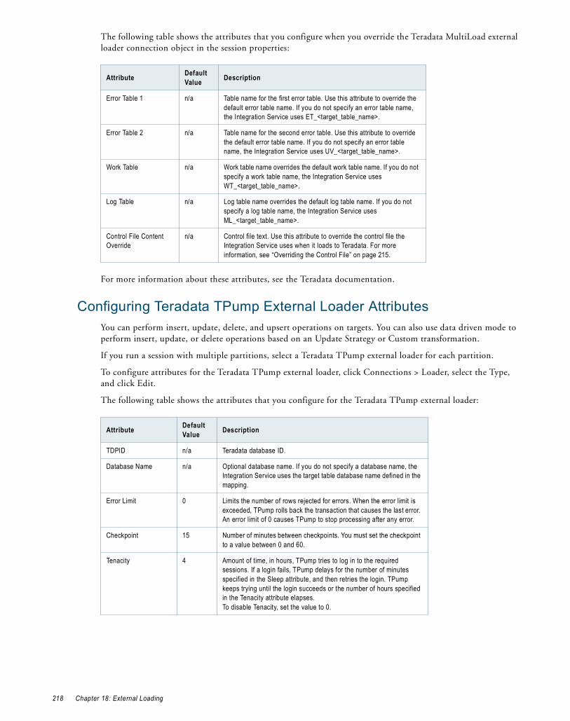
The following table shows the attributes that you configure when you override the Teradata MultiLoad external loader connection object in the session properties:
For more information about these attributes, see the Teradata documentation.
Configuring Teradata TPump External Loader AttributesYou can perform insert, update, delete, and upsert operations on targets. You can also use data driven mode to perform insert, update, or delete operations based on an Update Strategy or Custom transformation.
If you run a session with multiple partitions, select a Teradata TPump external loader for each partition.
To configure attributes for the Teradata TPump external loader, click Connections > Loader, select the Type, and click Edit.
The following table shows the attributes that you configure for the Teradata TPump external loader:
Attribute Default Value Description
Error Table 1 n/a Table name for the first error table. Use this attribute to override the default error table name. If you do not specify an error table name, the Integration Service uses ET_<target_table_name>.
Error Table 2 n/a Table name for the second error table. Use this attribute to override the default error table name. If you do not specify an error table name, the Integration Service uses UV_<target_table_name>.
Work Table n/a Work table name overrides the default work table name. If you do not specify a work table name, the Integration Service uses WT_<target_table_name>.
Log Table n/a Log table name overrides the default log table name. If you do not specify a log table name, the Integration Service uses ML_<target_table_name>.
Control File Content Override
n/a Control file text. Use this attribute to override the control file the Integration Service uses when it loads to Teradata. For more information, see “Overriding the Control File” on page 215.
Attribute Default Value Description
TDPID n/a Teradata database ID.
Database Name n/a Optional database name. If you do not specify a database name, the Integration Service uses the target table database name defined in the mapping.
Error Limit 0 Limits the number of rows rejected for errors. When the error limit is exceeded, TPump rolls back the transaction that causes the last error. An error limit of 0 causes TPump to stop processing after any error.
Checkpoint 15 Number of minutes between checkpoints. You must set the checkpoint to a value between 0 and 60.
Tenacity 4 Amount of time, in hours, TPump tries to log in to the required sessions. If a login fails, TPump delays for the number of minutes specified in the Sleep attribute, and then retries the login. TPump keeps trying until the login succeeds or the number of hours specified in the Tenacity attribute elapses.To disable Tenacity, set the value to 0.
218 Chapter 18: External Loading

Load Mode Upsert Mode to generate SQL commands: Insert, Delete, Update, Upsert, or Data Driven.When you select Data Driven loading, the Integration Service follows instructions in an Update Strategy or Custom transformation to determine how to flag rows for insert, delete, or update. The Integration Service writes a column in the target file or named pipe to indicate the update strategy. The control file uses these values to determine how to load data to the database. The Integration Service uses the following values to indicate the update strategy:0 - Insert1 - Update2 - Delete
Drop Error Tables Enabled Drops the TPump error tables before beginning the next session. Select this option to drop the tables, or clear it to keep them.
External Loader Executable
tpump Name and optional file path of the Teradata external loader executable. If the external loader executable directory is not in the system path, you must enter the full path.
Max Sessions 1 Maximum number of TPump sessions per TPump job. Each partition in a session starts its own TPump job. Running multiple TPump sessions causes the client and database to use more resources. Therefore, setting this value to a small number may improve performance.
Sleep 6 Number of minutes TPump waits before retrying a login. TPump tries until the login succeeds or the number of hours specified in the Tenacity attribute elapses.
Packing Factor 20 Number of rows that each session buffer holds. Packing improves network/channel efficiency by reducing the number of sends and receives between the target flat file and the Teradata database.
Statement Rate 0 Initial maximum rate, per minute, at which the TPump executable sends statements to the Teradata database. If you set this attribute to 0, the statement rate is unspecified.
Serialize Disabled Determines whether or not operations on a given key combination (row) occur serially.You may want to enable this if the TPump job contains multiple changes to one row. Sessions that contain multiple partitions with the same key range but different filter conditions may cause multiple changes to a single row. In this case, you may want to enable Serialize to prevent locking conflicts in the Teradata database, especially if you set the Pack attribute to a value greater than 1.If you enable Serialize, the Integration Service uses the primary key specified in the target table as the Key column. If no primary key exists in the target table, you must either clear this option or indicate the Key column in the data layout section of the control file.
Robust Disabled When Robust is not selected, it signals TPump to use simple restart logic. In this case, restarts cause TPump to begin at the last checkpoint. TPump reloads any data that was loaded after the checkpoint. This method does not have the extra overhead of the additional database writes in the robust logic.
No Monitor Enabled When selected, this attribute prevents TPump from checking for statement rate changes from, or update status information for, the TPump monitor application.
Is Staged Disabled Method of loading data. Select Is Staged to load data to a flat file staging area before loading to the database. Otherwise, the data is loaded to the database using a named pipe. For more information, see “External Loader Behavior” on page 204.
Error Database n/a Error database name. Use this attribute to override the default error database name. If you do not specify a database name, the Integration Service uses the target table database.
Attribute Default Value Description
Loading to Teradata 219

The following table shows the attributes that you configure when you override the Teradata TPump external loader connection object in the session properties:
For more information about these attributes, see the Teradata documentation.
Configuring Teradata FastLoad External Loader AttributesUse the following guidelines when you work with the FastLoad external loader:
♦ Each FastLoad job loads data to one Teradata database table. If you want to load data to multiple tables using FastLoad, you must create multiple FastLoad jobs.
♦ For a session with multiple partitions, use the round-robin partition type to route data to a single target file. For more information about partitioning sessions with external loaders, see “Partitioning Sessions with External Loaders” on page 205.
♦ The target table must be empty with no defined secondary indexes.
♦ FastLoad does not load duplicate rows from the output file to the target table in the Teradata database if the target table has a primary key.
♦ If you load date values to the target table, you must configure the date format for the column in the target table in the format YYYY-MM-DD.
♦ You cannot use FastLoad to load binary data.
♦ You can use comma (,), tab (\t), and pipe ( | ) as delimiters.
To configure attributes for the Teradata FastLoad external loader, click Connections > Loader, select the Type, and click Edit.
The following table shows the attributes that you configure for the Teradata FastLoad external loader:
Log Table Database n/a Log table database name. Use this attribute to override the default log table database name. If you do not specify a database name, the Integration Service uses the target table database.
User Variables n/a User-defined variable used in the default control file. For more information, see “Creating User Variables in the Control File” on page 215.
Attribute Default Value Description
Error Table n/a Error table name. Use this attribute to override the default error table name. If you do not specify an error table name, the Integration Service uses ET_<target_table_name><partition_number>.
Log Table n/a Log table name. Use this attribute to override the default log table name. If you do not specify a log table name, the Integration Service uses TL_<target_table_name><partition_number>.
Control File Content Override
n/a Control file text. Use this attribute to override the control file the Integration Service uses when it loads to Teradata. For more information, see “Overriding the Control File” on page 215.
Attribute Default Value Description
TDPID n/a Teradata database ID.
Database Name n/a Database name.
Error Limit 1,000,000 Maximum number of rows that FastLoad rejects before it stops loading data to the database table.
Attribute Default Value Description
220 Chapter 18: External Loading

The following table shows the attributes that you configure when you override the Teradata FastLoad external loader connection object in the session properties:
For more information about these attributes, see the Teradata documentation.
Checkpoint 0 Number of rows transmitted to the Teradata database between checkpoints. If processing stops while a FastLoad job is running, you can restart the job at the most recent checkpoint.If you enter 0, FastLoad does not perform checkpoint operations.
Tenacity 4 Number of hours FastLoad tries to log in to the required FastLoad sessions when the maximum number of load jobs are already running on the Teradata database. When FastLoad tries to log in to a new session, and the Teradata database indicates that the maximum number of load sessions is already running, FastLoad logs off all new sessions that were logged in, delays for the number of minutes specified in the Sleep attribute, and then retries the login. FastLoad keeps trying until it logs in for the required number of sessions or exceeds the number of hours specified in the Tenacity attribute.
Drop Error Tables Enabled Drops the FastLoad error tables before beginning the next session. FastLoad will not run if non-empty error tables exist from a prior job.Select this option to drop the tables, or clear it to keep them.
External Loader Executable
fastload Name and optional file path of the Teradata external loader executable. If the external loader executable directory is not in the system path, you must enter the full path.
Max Sessions 1 Maximum number of FastLoad sessions per FastLoad job. Max Sessions must be between 1 and the total number of access module processes (AMPs) on the system.
Sleep 6 Number of minutes FastLoad pauses before retrying a login. FastLoad tries until the login succeeds or the number of hours specified in the Tenacity attribute elapses.
Truncate Target Table
Disabled Truncates the target database table before beginning the FastLoad job. FastLoad cannot load data to non-empty tables.
Is Staged Disabled Method of loading data. Select Is Staged to load data to a flat file staging area before loading to the database. Otherwise, the data is loaded to the database using a named pipe. For more information, see “External Loader Behavior” on page 204.
Error Database n/a Error database name. Use this attribute to override the default error database name. If you do not specify a database name, the Integration Service uses the target table database.
Attribute Default Value Description
Error Table 1 n/a Table name for the first error table overrides the default error table name. If you do not specify an error table name, the Integration Service uses ET_<target_table_name>.
Error Table 2 n/a Table name for the second error table overrides the default error table name. If you do not specify an error table name, the Integration Service uses UV_<target_table_name>.
Control File Content Override
n/a Control file text. Use this attribute to override the control file the Integration Service uses when it loads to Teradata. For more information, see “Overriding the Control File” on page 215.
Attribute Default Value Description
Loading to Teradata 221
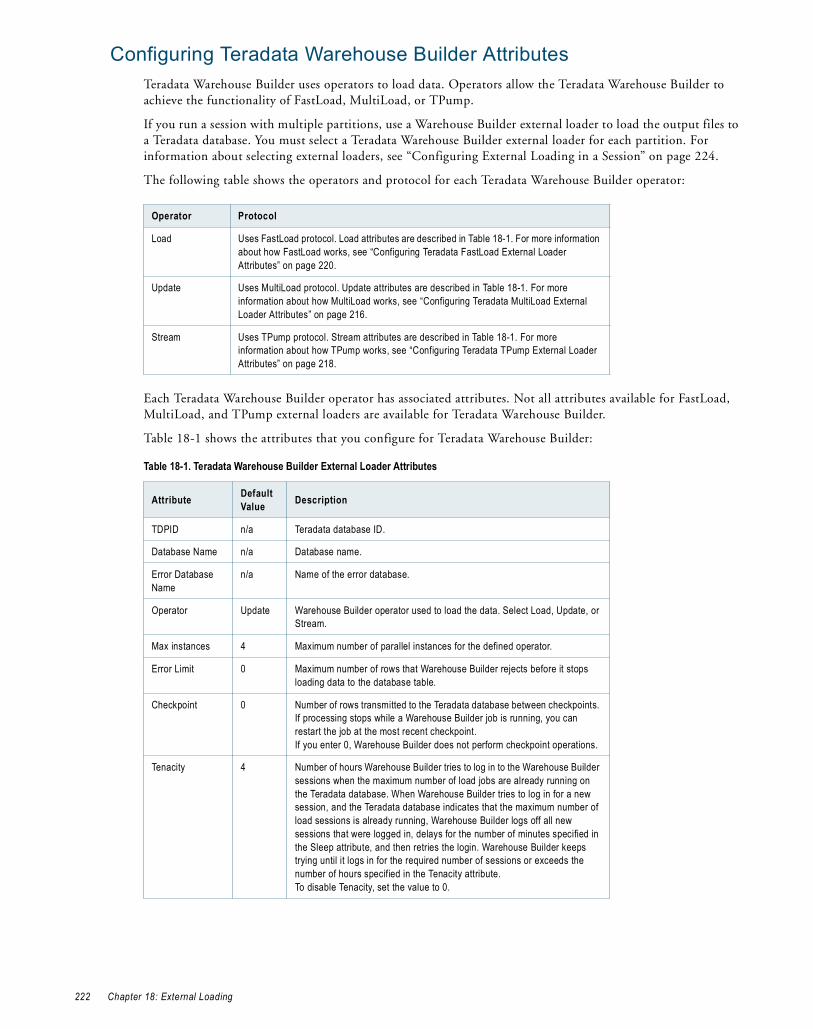
Configuring Teradata Warehouse Builder AttributesTeradata Warehouse Builder uses operators to load data. Operators allow the Teradata Warehouse Builder to achieve the functionality of FastLoad, MultiLoad, or TPump.
If you run a session with multiple partitions, use a Warehouse Builder external loader to load the output files to a Teradata database. You must select a Teradata Warehouse Builder external loader for each partition. For information about selecting external loaders, see “Configuring External Loading in a Session” on page 224.
The following table shows the operators and protocol for each Teradata Warehouse Builder operator:
Each Teradata Warehouse Builder operator has associated attributes. Not all attributes available for FastLoad, MultiLoad, and TPump external loaders are available for Teradata Warehouse Builder.
Table 18-1 shows the attributes that you configure for Teradata Warehouse Builder:
Operator Protocol
Load Uses FastLoad protocol. Load attributes are described in Table 18-1. For more information about how FastLoad works, see “Configuring Teradata FastLoad External Loader Attributes” on page 220.
Update Uses MultiLoad protocol. Update attributes are described in Table 18-1. For more information about how MultiLoad works, see “Configuring Teradata MultiLoad External Loader Attributes” on page 216.
Stream Uses TPump protocol. Stream attributes are described in Table 18-1. For more information about how TPump works, see “Configuring Teradata TPump External Loader Attributes” on page 218.
Table 18-1. Teradata Warehouse Builder External Loader Attributes
Attribute Default Value Description
TDPID n/a Teradata database ID.
Database Name n/a Database name.
Error Database Name
n/a Name of the error database.
Operator Update Warehouse Builder operator used to load the data. Select Load, Update, or Stream.
Max instances 4 Maximum number of parallel instances for the defined operator.
Error Limit 0 Maximum number of rows that Warehouse Builder rejects before it stops loading data to the database table.
Checkpoint 0 Number of rows transmitted to the Teradata database between checkpoints. If processing stops while a Warehouse Builder job is running, you can restart the job at the most recent checkpoint.If you enter 0, Warehouse Builder does not perform checkpoint operations.
Tenacity 4 Number of hours Warehouse Builder tries to log in to the Warehouse Builder sessions when the maximum number of load jobs are already running on the Teradata database. When Warehouse Builder tries to log in for a new session, and the Teradata database indicates that the maximum number of load sessions is already running, Warehouse Builder logs off all new sessions that were logged in, delays for the number of minutes specified in the Sleep attribute, and then retries the login. Warehouse Builder keeps trying until it logs in for the required number of sessions or exceeds the number of hours specified in the Tenacity attribute.To disable Tenacity, set the value to 0.
222 Chapter 18: External Loading

Load Mode Upsert Mode to generate SQL commands. Select Insert, Update, Upsert, Delete, or Data Driven.When you use the Update or Stream operators, you can choose Data Driven load mode. When you select data driven loading, the Integration Service follows instructions in Update Strategy or Custom transformations to determine how to flag rows for insert, delete, or update. The Integration Service writes a column in the target file or named pipe to indicate the update strategy. The control file uses these values to determine how to load data to the database. The Integration Service uses the following values to indicate the update strategy:0 - Insert1 - Update2 - Delete
Drop Error Tables Enabled Drops the Warehouse Builder error tables before beginning the next session. Warehouse Builder will not run if error tables containing data exist from a prior job. Clear the option to keep error tables.
Truncate Target Table
Disabled Specifies whether to truncate target tables. Enable this option to truncate the target database table before beginning the Warehouse Builder job.
External Loader Executable
tbuild Name and optional file path of the Teradata external loader executable file. If the external loader directory is not in the system path, enter the file path and file name.
Max Sessions 4 Maximum number of Warehouse Builder sessions per Warehouse Builder job. Max Sessions must be between 1 and the total number of access module processes (AMPs) on the system.
Sleep 6 Number of minutes Warehouse Builder pauses before retrying a login. Warehouse Builder tries until the login succeeds or the number of hours specified in the Tenacity attribute elapses.
Serialize Disabled Specifies whether operations on a column occur serially. Available with Update and Stream operators.
Packing Factor 20 Number of rows that each session buffer holds. Packing improves network/channel efficiency by reducing the number of sends and receives between the target file and the Teradata database. Available with Stream operator.
Robust Disabled Recovery or restart mode. When you disable Robust, the Stream operator uses simple restart logic. The Stream operator reloads any data that was loaded after the last checkpoint. When you enable Robust, Warehouse Builder uses robust restart logic. In robust mode, the Stream operator determines how many rows were processed since the last checkpoint. The Stream operator processes all the rows that were not processed after the last checkpoint. Available with Stream operator.
Is Staged Disabled Method of loading data. Select Is Staged to load data to a flat file staging area before loading to the database. Otherwise, the data is loaded to the database using a named pipe. For more information, see “External Loader Behavior” on page 204.
Error Database n/a Error database name. Use this attribute to override the default error database name. If you do not specify a database name, the Integration Service uses the target table database.
Work Table Database
n/a Work table database name. Use this attribute to override the default work table database name. If you do not specify a database name, the Integration Service uses the target table database.
Log Table Database
n/a Log table database name. Use this attribute to override the default log table database name. If you do not specify a database name, the Integration Service uses the target table database.
Note: Available attributes depend on the operator you select.
Table 18-1. Teradata Warehouse Builder External Loader Attributes
Attribute Default Value Description
Loading to Teradata 223

The following table shows the attributes that you configure when you override the Teradata Warehouse Builder external loader connection object in the session properties:
For more information about these attributes, see the Teradata documentation.
Configuring External Loading in a SessionBefore you can configure external loading in a session, you must create an external loader connection in the Workflow Manager and configure the external loader attributes. For more information about creating external loader connections, see the PowerCenter Workflow Basics Guide.
Complete the following steps to use an external loader for a session:
1. Configure the session to write to flat file instead of to a relational database. For more information, see “Configuring a Session to Write to a File” on page 224.
2. Configure the file properties. For more information, see “Configuring File Properties” on page 225.
3. Select an external loader connection in the session properties. For more information, see “Selecting an External Loader Connection” on page 225.
Configuring a Session to Write to a FileTo use an external loader, create the target definition in the mapping according to the target database type. The session configures a relational target type by default. To select an external loader connection, you must configure the session to write to a file instead of a relational target. To configure the session to write to a file, change the writer type from relational writer to file writer. You change the writer type using the Writers settings on the Mapping tab.
To change the writer type for the target, select the target instance and change the writer type from Relational Writer to File Writer.
Attribute Default Value Description
Error Table 1 n/a Table name for the first error table. Use this attribute to override the default error table name. If you do not specify an error table name, the Integration Service uses ET_<target_table_name>.
Error Table 2 n/a Table name for the second error table. Use this attribute to override the default error table name. If you do not specify an error table name, the Integration Service uses UV_<target_table_name>.
Work Table n/a Work table name. This attribute overrides the default work table name. If you do not specify a work table name, the Integration Service uses WT_<target_table_name>.
Log Table n/a Log table name. This attribute overrides the default log table name. If you do not specify a log table name, the Integration Service uses RL_<target_table_name>.
Control File Content Override
n/a Control file text. This attribute overrides the control file the Integration Service uses to loads to Teradata. For more information, see “Overriding the Control File” on page 215.
Note: Available attributes depend on the operator you select.
224 Chapter 18: External Loading

Configuring File PropertiesAfter you configure the session to write to a file, you can set the file properties. You need to specify the output file name and directory, and the reject file name and directory. You configure these properties in the Properties settings on the Mapping tab. To set the file properties, select the target instance.
The following table shows the attributes in Properties settings:
Note: Do not select Merge Partitioned Files or enter a merge file name. You cannot merge partitioned output files when you use an external loader.
Selecting an External Loader ConnectionAfter you configure file properties, you can select the external loader connection. To select the external loader connection, choose the connection type and the connection object. You configure connection options in the Connections settings on the Mapping tab.
If the session contains multiple partitions, and you choose a loader that can load from multiple output files, you can select a different connection for each partition, but each connection must be of the same type. For example, you can select different Teradata TPump external loader connections for each partition, but you cannot select a Teradata TPump connection for one partition and an Oracle connection for another partition.
If the session contains multiple partitions, and you choose a loader that can load from only one output file, use round-robin partitioning to route data to a single target file. You can choose a loader for each connection, but the Integration Service uses the connection for the first partition.
Attribute Description
Output File Directory Name and path of the output file directory. Enter the directory name in this field. By default, the Integration Service writes output files to the directory $PMTargetFileDir.If you enter a full directory and file name in the Output Filename field, clear this field. External loader sessions may fail if you use double spaces in the path for the output file.
Output Filename Name of the output file. Enter the file name, or file name and path. By default, the Workflow Manager names the target file based on the target definition used in the mapping: target_name.out. External loader sessions may fail if you use double spaces in the path for the output file.
Reject File Directory Name and path of the reject file directory. By default, the Integration Service writes all reject files to the directory $PMBadFileDir.If you enter a full directory and file name in the Reject Filename field, clear this field.
Reject Filename Name of the reject file. Enter the file name, or file name and directory. The Integration Service appends information in this field to that entered in the Reject File Directory field. For example, if you have “C:/reject_file/” in the Reject File Directory field, and enter “filename.bad” in the Reject Filename field, the Integration Service writes rejected rows to C:/reject_file/filename.bad.By default, the Integration Service names the reject file after the target instance name: target_name.bad.You can also enter a reject file session parameter to represent the reject file or the reject file and directory. Name all reject file parameters $BadFileName. For more information about session parameters, see “Parameter Files” on page 181.
Set File Properties Definition of flat file properties. When you use an external loader, you must define the flat file properties by clicking the Set File Properties link.For Oracle external loaders, the target flat file can be fixed-width or delimited.For Sybase IQ external loaders, the target flat file can be fixed-width or delimited.For Teradata external loaders, the target flat file must be fixed-width. For IBM DB2 external loaders, the target flat file must be delimited.For more information about flat file properties, see the PowerCenter Workflow Basics Guide.
Configuring External Loading in a Session 225

For more information about running external loader sessions with multiple partitions, see “Partitioning Sessions with External Loaders” on page 205.
To select an external loader connection:
1. On the Mapping tab, select the target instance in the Navigator.
2. Select the Loader connection type.
3. Click the Open button in the Value field.
4. Select a connection object or variable:
♦ Use object. Select a loader connection object. Click the Override button to override connection attributes. The attributes you can override vary according to loader type.
♦ Use connection variable. Use the $LoaderConnectionName session parameter, and define the parameter in the parameter file. Override connection attributes in the parameter file.
For information about overriding connection attributes and parameter files, see the PowerCenter Workflow Basics Guide.
5. Click OK.
TroubleshootingI am trying to set up a session to load data to an external loader, but I cannot select an external loader connection in the session properties.Verify that the mapping contains a relational target. When you create the session, select a file writer in the Writers settings of the Mapping tab in the session properties. Then open the Connections settings and select an external loader connection.
I am trying to run a session that uses TPump, but the session fails. The session log displays an error saying that the Teradata output file name is too long.The Integration Service uses the Teradata output file name to generate names for the TPump error and log files and the log table name. To generate these names, the Integration Service adds a prefix of several characters to the output file name. It adds three characters for sessions with one partition and five characters for sessions with multiple partitions.
Teradata allows log table names of up to 30 characters. Because the Integration Service adds a prefix, if you are running a session with a single partition, specify a target output file name with a maximum of 27 characters, including the file extension. If you are running a session with multiple partitions, specify a target output file name with a maximum of 25 characters, including the file extension.
I tried to load data to Teradata using TPump, but the session failed. I corrected the error, but the session still fails.Occasionally, Teradata does not drop the log table when you rerun the session. Check the Teradata database, and manually drop the log table if it exists. Then rerun the session.
226 Chapter 18: External Loading

C H A P T E R 1 9
FTP
This chapter includes the following topics:
♦ Overview, 227
♦ Integration Service Behavior, 228
♦ Configuring FTP in a Session, 229
OverviewYou can configure a session to use File Transfer Protocol (FTP) to read from flat file or XML sources or write to flat file or XML targets. The Integration Service can use FTP to access any machine it can connect to, including mainframes. With both source and target files, use FTP to transfer the files directly or stage them in a local directory. Access source files directly or use a file list to access indirect source files in a session.
To use FTP file sources and targets in a session, complete the following tasks:
1. Create an FTP connection object in the Workflow Manager and configure the connection attributes. For more information about creating FTP connections, see the PowerCenter Workflow Basics Guide.
2. Configure the session to use the FTP connection object in the session properties. For more information, see “Configuring FTP in a Session” on page 229.
Configure an FTP connection to use SSH File Transfer Protocol (SFTP) if you are connecting to an SFTP server. SFTP enables file transfer over a secure data stream. The Integration Service creates an SSH2 transport layer that enables a secure connection and access to the files on an SFTP server.
Rules and GuidelinesUse the following guidelines when using FTP with flat file or XML sources and targets:
♦ Specify the source or target output directory in the session properties. If you do not specify a directory, the Integration Service stages the file in the directory where the Integration Service runs on UNIX or in the Windows system directory.
♦ You cannot run sessions concurrently if the sessions use the same FTP source file or target file located on a mainframe.
♦ If you abort a workflow containing a session that stages an FTP source or target from a mainframe, you may need to wait for the connection to timeout before you can run the workflow again.
♦ To run a session using an FTP connection for an SFTP server that requires public key authentication, the public key and private key files must be accessible on nodes where the session will run.
227

Integration Service BehaviorThe behavior of the Integration Service using FTP depends on the way you configure the FTP connection and the session. The Integration Service can use FTP to access source and target files in the following ways:
♦ Source files. Stage source files on the machine hosting the Integration Service or access the source files directly from the FTP host. Use a single source file or a file list that contains indirect source files for a single source instance.
♦ Target files. Stage target files on the machine hosting the Integration Service or write to the target files on the FTP host.
Select staging options for the session when you select the FTP connection object in the session properties. You can also stage files by creating a pre- or post-session shell command to copy the files to or from the FTP host. You generally get better performance when you access source files directly with FTP. However, you may want to stage FTP files to keep a local archive.
Using FTP with Source FilesUse FTP in a session that reads flat file or XML file sources. You can stage the source files for a session on the machine hosting the Integration Service. Use a single source file or a file list for each source instance.
When you stage source files, the Integration Service copies the source file from the FTP host to the machine hosting the Integration Service. The Integration Service uses the local file as the source file for the session. If the local source file exists, the Integration Service replaces the file.
The following table describes the behavior of the Integration Service using FTP with source files:
Using FTP with Target FilesUse FTP in a session that writes to flat file or XML file targets. You can stage the target files on the machine hosting the Integration Service before copying them to the FTP host.
When you stage target files, the Integration Service creates a target file locally and transfers it to the FTP host after the session completes. If you do not stage the target file, the Integration Service writes directly to the target file on the FTP host. If the target file exists, the Integration Service truncates the file.
If you have the Partitioning option, use FTP for multiple target partition instances. You can write to multiple target files or a merge file on the Integration Service or the FTP host.
RELATED TOPICS:♦ “Partitioning File Targets” on page 22
Source Type Is Staged Integration Service Behavior
Direct Yes Integration Service copies the file from the FTP host to the machine hosting the Integration Service after the session begins.
Direct No Integration Service uses FTP to access the source file directly.
Indirect Yes Integration Service reads the file list and copies the file list and the source files to the machine hosting the Integration Service after the session begins.
Indirect No Integration Service copies the file list to the machine hosting the Integration Service after the session begins. The Integration Service uses FTP to access the source files directly.
228 Chapter 19: FTP
Configuring FTP in a SessionBefore you can configure a session to use FTP, you must create an FTP connection object in the Workflow Manager. The Integration Service uses the FTP connection attributes to connect to the FTP server.
After you create an FTP connection in the Workflow Manager, you can configure a session to use FTP. To use a secure connection, select an FTP connection object configured for SFTP. Use any session with flat file or XML sources or targets.
To configure the session, complete the following tasks for each source and target that requires an FTP connection:
♦ Select an FTP connection.
♦ Configure source file properties.
♦ Configure target file properties.
To stage the source or target file on the Integration Service machine, edit the FTP connection in the session properties to configure the directory and file name for the staged file.
Configuring SFTP in a SessionTo run a session using an FTP connection for an SFTP server that requires public key authentication, the public key and private key files must be accessible on nodes where the session will run.
If the Integration Service is configured to run on primary and backup nodes, make the key files accessible on each node configured to run the Integration Service process.
If the Integration Service is configured to run on a grid, make the key files accessible on each node configured to run on the grid. If you cannot put the files on each node in the grid, create a resource in the domain and assign it to each node where you put the files. When you create a session, configure it to use the resource.
For example, create a custom resource called SFTP. When you create a session, you can require the session to use the SFTP resource. The Load Balancer will only dispatch the session to nodes where the key files are accessible.
Selecting an FTP ConnectionTo configure a session to use FTP, select the connection type and the connection object. Select an FTP connection object for each source and target that will use the FTP connection. To use SFTP, select an FTP connection object that is configured for SFTP. You configure connection options in the Connections settings on the Mapping tab.
To select an FTP connection for a source or target instance:
1. On the Mapping tab, select the source or target instance in the Transformation view.
2. Select the FTP connection type.
3. Click the Open button in the Value field.
4. Select a connection object or variable:
♦ Use object. Select an FTP connection object. Click the Override button to override connection attributes.
♦ Use connection variable. Use the $FTPConnectionName session parameter, and define the parameter in the parameter file. Override connection attributes in the parameter file.
Configuring FTP in a Session 229

You can override the following attributes:
5. Click OK.
Configuring Source File PropertiesIf you access source files with FTP, configure the source file properties after you choose the FTP connection for the source instance. The source file properties determine the source file type and the staging location. You can configure source file properties in the Properties settings on the Mapping tab.
If you stage the source file, select the source file name, directory, and file type.
If you do not stage the source file, specify the source file type. The Integration Service uses the remote file name and directory from the FTP connection object and ignores the source file name and directory.
The following table describes the source file properties on the Mapping tab:
Configuring Target File PropertiesIf you write to target files with FTP, specify the target file properties after you specify the FTP connection for the target instance. The target file properties determine the reject file and directory and staging location. Specify target file properties in the Properties settings on the Mapping tab.
Attribute Description
Remote Filename The remote file name for the source or target. If you use an indirect source file, enter the indirect source file name.You must use 7-bit ASCII characters for the file name. The session fails if you use a remote file name with Unicode characters.If you enter a fully qualified name for the source file name, the Integration Service ignores the path entered in the Default Remote Directory field. The session will fail if you enclose the fully qualified file name in single or double quotation marks.You can use a parameter or variable for the remote file name. Use any parameter or variable type that you can define in the parameter file. For example, you can use a session parameter, $ParamMyRemoteFile, as the source or target remote file name, and set $ParamMyRemoteFile to the file name in the parameter file.
Is Staged Stages the source or target file on the Integration Service. Default is not staged.
Is Transfer Mode ASCII
Changes the transfer mode. When enabled, the Integration Service uses ASCII transfer mode. You can use ASCII mode when transferring files on Windows machines to ensure that the end of line character is translated properly in text files. When disabled, the Integration Service uses binary transfer mode. Use binary transfer mode when transferring files on UNIX machines. Default is disabled.
Attribute Description
Source File Type Indicates whether the source file contains the source data or a list of files with the same file properties. Choose Direct if the source file contains the source data. Choose Indirect if the source file contains a list of files.
Source File Directory Name and path of the local source file directory used to stage the source data. By default, the Integration Service uses the service process variable directory, $PMSourceFileDir, for file sources. The Integration Service concatenates this field with the Source file name field when it runs the session.If you do not stage the source file, the Integration Service uses the file name and directory from the FTP connection object. The Integration Service ignores this field if you enter a fully qualified file name in the Source file name field.
Source File Name Name of the local source file used to stage the source data. You can enter the file name or the file name and path. If you enter a fully qualified file name, the Integration Service ignores the Source file directory field.If you do not stage the source file, the Integration Service uses the remote file name and default directory from the FTP connection object.
230 Chapter 19: FTP

If you stage the target file, configure the target file name and directory and the reject file name and directory. If you do not stage the target file, configure the reject file and directory. The Integration Service uses the remote file name and directory from the FTP connection object.
If you have the Partitioning option, you can also select merge file properties.
The following table describes the target file attributes on the Mapping tab:
Partitioning FTP File TargetsWhen you choose an FTP connection type for the partitioned targets in a session, you configure FTP settings for the target partitions. You can merge the target files or individual target files for each partition.
Use the following rules and guidelines when you configure FTP settings for target partitions:
♦ You must use an FTP connection for each target partition.
♦ You can choose to stage the files when selecting the connection object for the target partition. You must stage the files to use sequential merge.
♦ If the FTP connections for the target partitions have any settings other than a remote file name, the Integration Service does not create a merge file.
The following table describes the actions of the Integration Service with partitioned FTP file targets:
Attribute Description
Output File Directory Name and path of the local target file directory used to stage the target data. By default, the Integration Service uses the service process variable directory, $PMTargetFileDir. The Integration Service concatenates this field with the Output file name field when it runs the session.If you do not stage the target file, the Integration Service uses the file name and directory from the FTP connection object. The Integration Service ignores this field if you enter a fully qualified file name in the Output file name field.
Output File Name Name of the local target file used to stage the target data. You can enter the file name, or the file name and path. If you enter a fully qualified file name, the Integration Service ignores the Output file directory field.If you do not stage the source file, the Integration Service uses the remote file name and default directory from the FTP connection object.
Merge Type Integration Service Behavior
No Merge If you stage the files, The Integration Service creates one target file for each partition. At the end of the session, the Integration Service transfers the target files to the remote location.If you do not stage the files, the Integration Service generates a target file for each partition at the remote location.
Sequential Merge Enable the Is Staged option in the connection object. Integration Service creates one output file for each partition. At the end of the session, the Integration Service merges the individual output files into a single merge file, deletes the individual output files, and transfers the merge file to the remote location.
Configuring FTP in a Session 231

File List If you stage the files, the Integration Service creates the following files:- Output file for each partition- File list that contains the names and paths of the local files- File list that contains the names and paths of the remote filesAt the end of the session, the Integration Service transfers the files to the remote location. If the individual target files are in the Merge File Directory, file list contains relative paths. Otherwise, the file list contains absolute paths.If you do not stage the files, the Integration Service writes the data for each partition at the remote location and creates a remote file list that contains a list of the individual target files.Use the file list as a source file in another mapping.
Concurrent Merge If you stage the files, the Integration Service concurrently writes the data for all target partitions to a local merge file. At the end of the session, the Integration Service transfers the merge file to the remote location. The Integration Service does not write to any intermediate output files.If you do not stage the files, the Integration Service concurrently writes the target data for all partitions to a merge file at the remote location.
Merge Type Integration Service Behavior
232 Chapter 19: FTP

C H A P T E R 2 0
Session Caches
This chapter includes the following topics:
♦ Overview, 233
♦ Cache Memory, 234
♦ Cache Files, 235
♦ Configuring the Cache Size, 237
♦ Cache Partitioning, 239
♦ Aggregator Caches, 240
♦ Joiner Caches, 242
♦ Lookup Caches, 245
♦ Rank Caches, 246
♦ Sorter Caches, 247
♦ XML Target Caches, 248
♦ Optimizing the Cache Size, 249
OverviewThe Integration Service allocates cache memory for XML targets and Aggregator, Joiner, Lookup, Rank, and Sorter transformations in a mapping. The Integration Service creates index and data caches for the XML targets and Aggregator, Joiner, Lookup, and Rank transformations. The Integration Service stores key values in the index cache and output values in the data cache. The Integration Service creates one cache for the Sorter transformation to store sort keys and the data to be sorted.
You configure memory parameters for the caches in the session properties. When you first configure the cache size, you can calculate the amount of memory required to process the transformation or you can configure the Integration Service to automatically configure the memory requirements at run time.
After you run a session, you can tune the cache sizes for the transformations in the session. You can analyze the transformation statistics to determine the cache sizes required for optimal session performance, and then update the configured cache sizes.
If the Integration Service requires more memory than what you configure, it stores overflow values in cache files. When the session completes, the Integration Service releases cache memory, and in most circumstances, it deletes the cache files.
233

If the session contains multiple partitions, the Integration Service creates one memory cache for each partition. In particular situations, the Integration Service uses cache partitioning, creating a separate cache for each partition.
The following table describes the type of information that the Integration Service stores in each cache:
Cache MemoryThe Integration Service creates each memory cache based on the configured cache size. When you create a session, you can configure the cache sizes for each transformation instance in the session properties.
The Integration Service might increase the configured cache size for one of the following reasons:
♦ The configured cache size is less than the minimum cache size required to process the operation. The Integration Service requires a minimum amount of memory to initialize each session. If the configured cache size is less than the minimum required cache size, then the Integration Service increases the configured cache size to meet the minimum requirement. If the Integration Service cannot allocate the minimum required memory, the session fails.
♦ The configured cache size is not a multiple of the cache page size. The Integration Service stores cached data in cache pages. The cached pages must fit evenly into the cache. Thus, if you configure 10 MB (1,048,576 bytes) for the cache size and the cache page size is 10,000 bytes, then the Integration Service increases the configured cache size to 1,050,000 bytes to make it a multiple of the 10,000-byte page size.
When the Integration Service increases the configured cache size, it continues to run the session and writes a message similar to the following message in the session log:
MAPPING> TE_7212 Increasing [Index Cache] size for transformation <transformation name> from <configured index cache size> to <new index cache size>.
Review the session log to verify that enough memory is allocated for the minimum requirements.
For optimal performance, set the cache size to the total memory required to process the transformation. If there is not enough cache memory to process the transformation, the Integration Service processes some of the transformation in memory and pages information to disk to process the rest.
Use the following information to understand how the Integration Service handles memory caches differently on 32-bit and 64-bit machines:
♦ An Integration Service process running on a 32-bit machine cannot run a session if the total size of all the configured session caches is more than 2 GB. If you run the session on a grid, the total cache size of all session threads running on a single node must not exceed 2 GB.
♦ If a grid has 32-bit and 64-bit Integration Service processes and a session exceeds 2 GB of memory, you must configure the session to run on an Integration Service on a 64-bit machine.
Mapping Object Cache Types and Descriptions
Aggregator - Index. Stores group values as configured in the group by ports.- Data. Stores calculations based on the group by ports.
Joiner - Index. Stores all master rows in the join condition that have unique keys.- Data. Stores master source rows.
Lookup - Index. Stores lookup condition information.- Data. Stores lookup data that is not stored in the index cache.
Rank - Index. Stores group values as configured in the group by ports.- Data. Stores ranking information based on the group by ports.
Sorter - Sorter. Stores sort keys and data.
XML Target - Index. Stores primary and foreign key information in separate caches.- Data. Stores XML row data while it generates the XML target.
234 Chapter 20: Session Caches

RELATED TOPICS:♦ “Running Workflows on a Grid” on page 152
Cache FilesWhen you run a session, the Integration Service creates at least one cache file for each transformation. If the Integration Service cannot process a transformation in memory, it writes the overflow values to the cache files.
The following table describes the types of cache files that the Integration Service creates for different mapping objects:
The Integration Service creates cache files based on the Integration Service code page.
When you run a session, the Integration Service writes a message in the session log indicating the cache file name and the transformation name. When a session completes, the Integration Service releases cache memory and usually deletes the cache files. You may find index and data cache files in the cache directory under the following circumstances:
♦ The session performs incremental aggregation.
♦ You configure the Lookup transformation to use a persistent cache.
♦ The session does not complete successfully. The next time you run the session, the Integration Service deletes the existing cache files and creates new ones.
Note: Since writing to cache files can slow session performance, configure the cache sizes to process the transformation in memory.
Naming Convention for Cache FilesThe Integration Service uses the different naming conventions for index, data, and sorter cache files.
The following table describes the naming convention for each type of cache file:
Mapping Object Cache File
Aggregator, Joiner, Lookup, and Rank transformations
The Integration Service creates the following types of cache files:- One header file for each index cache and data cache- One data file for each index cache and data cache
Sorter transformation The Integration Service creates one sorter cache file.
XML target The Integration Service creates the following types of cache files:- One data cache file for each XML target group- One primary key index cache file for each XML target group- One foreign key index cache file for each XML target group
Cache Files Naming Convention
Data and sorter [<Name Prefix> | <prefix> <session ID>_<transformation ID>]_[partition index]_[OS][BIT].<suffix> [overflow index]
Index <prefix> <session id>_<transformation id>_<group id>_<key type>.<suffix> <overflow>
Cache Files 235

The following table describes the components of the cache file names:
For example, the name of the data file for the index cache is PMLKUP748_2_5S32.idx1. PMLKUP identifies the transformation type as Lookup, 748 is the session ID, 2 is the transformation ID, 5 is the partition index, S (Solaris) is the operating system, and 32 is the bit platform.
Cache File DirectoryThe Integration Service creates the cache files by default in the $PMCacheDir directory. If the Integration Service process does not find the directory, it fails the session and writes a message to the session log indicating that it could not create or open the cache file.
The Integration Service may create multiple cache files. The number of cache files is limited by the amount of disk space available in the cache directory.
File Name Component Description
Name Prefix Cache file name prefix configured in the Lookup transformation. For Lookup transformation cache file.
Prefix Describes the type of transformation:- Aggregator transformation is PMAGG.- Joiner transformation is PMJNR.- Lookup transformation is PMLKUP.- Rank transformation is PMAGG.- Sorter transformation is PMSORT.- XML target is PMXML.
Session ID Session instance ID number.
Transformation ID Transformation instance ID number.
Group ID ID for each group in a hierarchical XML target. The Integration Service creates one index cache for each group. For XML target cache file.
Key Type Type of key. Can be foreign key or primary key. For XML target cache file.
Partition Index If the session contains more than one partition, this identifies the partition number. The partition index is zero-based, so the first partition has no partition index. Partition index 2 indicates a cache file created in the third partition.
OS Identifies the operating system of the machine running the Integration Service process:- W is Windows.- H is HP-UX.- S is Solaris.- A is AIX.- L is Linux.- M is Mainframe.For Lookup transformation cache file.
BIT Identifies the bit platform of the machine running the Integration Service process: 32-bit or 64-bit. For Lookup transformation cache file.
Suffix Identifies the type of cache file:- Index cache file is .idx0 for the header file and .idxn for the data files.- Data cache file is .dat0 for the header file and .datn for the data files.- Sorter cache file is .PMSORT().
Overflow Index If a cache file handles more than 2 GB of data, the Integration Service creates more cache files. When creating these files, the Integration Service appends an overflow index to the file name, such as PMAGG*.idx2 and PMAGG*.idx3. The number of cache files is limited by the amount of disk space available in the cache directory.
236 Chapter 20: Session Caches

If you run the Integration Service on a grid and only some Integration Service nodes have fast access to the shared cache file directory, configure each session with a large cache to run on the nodes with fast access to the directory. To configure a session to run on a node with fast access to the directory, complete the following steps:
1. Create a PowerCenter resource.
2. Make the resource available to the nodes with fast access to the directory.
3. Assign the resource to the session.
If all Integration Service processes in a grid have slow access to the cache files, set up a separate, local cache file directory for each Integration Service process. An Integration Service process may have faster access to the cache files if it runs on the same machine that contains the cache directory.
Configuring the Cache SizeConfigure the amount of memory for a cache in the session properties. The cache size specified in the session properties overrides the value set in the transformation properties.
The amount of memory you configure depends on how much memory cache and disk cache you want to use. If you configure the cache size and it is not enough to process the transformation in memory, the Integration Service processes some of the transformation in memory and pages information to cache files to process the rest of the transformation. For optimal session performance, configure the cache size so that the Integration Service can process all data in memory.
If the session is reusable, all instances of the session use the cache size configured in the reusable session properties. You cannot override the cache size in the session instance.
Use one of the following methods to configure a cache size:
♦ Cache calculator. Use the calculator to estimate the total amount of memory required to process the transformation. For more information, see “Calculating the Cache Size” on page 237.
♦ Auto cache memory. Use auto memory to specify a maximum limit on the cache size that is allocated for processing the transformation. Use this method if the machine on which the Integration Service process runs has limited cache memory. For more information, see “Using Auto Memory Size” on page 238.
♦ Numeric value. Configure a specific value for the cache size. Configure a specific value when you want to tune the cache size. For more information, see “Configuring a Numeric Cache Size” on page 238.
You configure the memory requirements differently when the Integration Service uses cache partitioning. If the Integration Service uses cache partitioning, it allocates the configured cache size for each partition. To configure the memory requirements for a transformation with cache partitioning, calculate the total requirements for the transformation and divide by the number of partitions.
The cache size requirements for a transformation may change when the inputs to the transformation change. Monitor the cache sizes in the session logs on a regular basis to help you tune the cache size.
RELATED TOPICS:♦ “Configuring the Cache Size for Cache Partitioning” on page 240
♦ “Optimizing the Cache Size” on page 249
Calculating the Cache SizeUse the cache calculator to estimate the total amount of memory required to process the transformation. You must provide inputs to calculate the cache size. The inputs depend on the type of transformation. For example, to calculate the cache size for an Aggregator transformation, you supply the number of groups.
You can select one of the following modes in the cache calculator:
Configuring the Cache Size 237

♦ Auto. Choose auto mode if you want the Integration Service to determine the cache size at run time based on the maximum memory configured on the Config Object tab.
♦ Calculate. Select to calculate the total requirements for a transformation based on inputs. The cache calculator requires different inputs for each transformation. You must select the applicable cache type to apply the calculated cache size. For example, to apply the calculated cache size for the data cache and not the index cache, select only the Data Cache Size option.
The cache calculator estimates the cache size required for optimal session performance based on your input. After you configure the cache size and run the session, you can review the transformation statistics in the session log to tune the configured cache size.
Note: You cannot use the cache calculator to estimate the cache size for an XML target.
RELATED TOPICS:♦ “Optimizing the Cache Size” on page 249
Using Auto Memory SizeUse auto cache memory to specify a maximum limit on the cache size that is allocated for processing the transformation. If you use auto cache memory, you configure the Integration Service to determine the cache size for a transformation at run time.
The Integration Service allocates memory cache based on the maximum memory size specified in the auto memory attributes in the session properties. The Integration Service distributes the maximum cache size specified among all transformations in the session.
You might use auto memory cache if the machine on which the Integration Service process runs has limited cache memory. For example, you use the cache calculator to determine that the Aggregator transformation requires 1 GB of cache memory to process the transformation. The machine only has 800 MB of cache memory available.
When you configure a numeric value and a percentage for the auto cache memory, the Integration Service compares the values and uses the lesser of the two for the maximum memory limit. The Integration Service allocates up to 800 MB as long as 800 MB is less than 5% of the total memory.
To configure auto cache memory, you can use the cache calculator or you can enter ‘Auto’ directly into the session properties. By default, transformations use auto cache memory.
If a session has multiple transformations that require caching, you can configure some transformations with auto memory cache and other transformations with numeric cache sizes. The Integration Service allocates the maximum memory specified for auto caching in addition to the configured numeric cache sizes. For example, a session has three transformations. You assign auto caching to two transformations and specify a maximum memory cache size of 800 MB. You specify 500 MB as the cache size for the third transformation. The Integration Service allocates a total of 1,300 MB of memory.
If the Integration Service uses cache partitioning, the Integration Service distributes the maximum cache size specified for the auto cache memory across all transformations in the session and divides the cache memory for each transformation among all of its partitions.
Configuring a Numeric Cache SizeYou can configure a specific value for the cache size. You configure a specific value when you tune a cache size. The first time you configure the cache size, you can use the cache calculator or auto cache memory. After you configure the cache size and run the session, you can analyze the transformation statistics in the session log to tune the cache size. The session log shows the cache size required to process the transformation in memory without paging to disk. Use the cache size specified in the session log for optimal session performance.
238 Chapter 20: Session Caches

Steps to Configure the Cache SizeYou can configure the cache size for a transformation in the session properties. When you configure the cache size, you specify the total requirements for the transformation, unless the Integration Service uses cache partitioning.
You configure the cache size differently if the Integration Services uses cache partitioning. To calculate the cache size when the Integration Service uses cache partitioning, calculate the total requirements for the transformation, and divide by the number of partitions.
To configure the cache size in the session:
1. In the Workflow Manager, open the session.
2. Click the Mapping tab.
3. Select the mapping object in the left pane.
The right pane of the Mapping tab shows the object properties where you can configure the cache size.
4. Use one of the following methods to set the cache size:
Enter a value for the cache size, click OK, and then skip to step 8. If you enter a value, all values are in bytes by default. However, you can enter a value and specify one of the following units: KB, MB, or GB. If you enter the units, do not enter a space between the value and unit. For example, enter 350000KB, 200MB, or 1GB.
or
Enter ‘Auto’ for the cache size, click OK, and then skip to step 8.
or
Click the Open button to open the cache calculator.
5. Select a mode.
Select the Auto mode to limit the amount of cache allocated to the transformation. Skip to step 8.
or
Select the Calculate mode to calculate the total memory requirement for the transformation.
6. Provide the input based on the transformation type, and click Calculate.
Note: If the input value is too large and you cannot enter the value in the cache calculator, use auto memory cache.
The cache calculator calculates the cache sizes in kilobytes.
7. If the transformation has a data cache and index cache, select Data Cache Size, Index Cache Size, or both.
8. Click OK to apply the calculated values to the cache sizes you selected in step 7.
Cache PartitioningWhen you create a session with multiple partitions, the Integration Service may use cache partitioning for the Aggregator, Joiner, Lookup, Rank, and Sorter transformations. When the Integration Service partitions a cache, it creates a separate cache for each partition and allocates the configured cache size to each partition. The Integration Service stores different data in each cache, where each cache contains only the rows needed by that partition. As a result, the Integration Service requires a portion of total cache memory for each partition.
When the Integration Service uses cache partitioning, it accesses the cache in parallel for each partition. If it does not use cache partitioning, it accesses the cache serially for each partition.
Cache Part it ioning 239

The following table describes the situations when the Integration Service uses cache partitioning for each applicable transformation:
Configuring the Cache Size for Cache PartitioningYou configure the memory requirements differently when the Integration Service uses cache partitioning. If the Integration Service uses cache partitioning, it allocates the configured cache size for each partition. To configure the memory requirements for a transformation with cache partitioning, calculate the total requirements for the transformation and divide by the number of partitions.
For example, you create four partitions in a session with an Aggregator transformation. You determine that an Aggregator transformation requires 400 MB of memory for the data cache. Configure 100 MB for the data cache size for the Aggregator transformation. When you run the session, the Integration Service allocates 100 MB for each partition, using a total of 400 MB for the Aggregator transformation.
Use the cache calculator to calculate the total requirements for the transformation. If you use dynamic partitioning, you can determine the number of partitions based on the dynamic partitioning method. If you use dynamic partitioning based on the nodes in a grid, the Integration Service creates one partition for each node. If you use dynamic partitioning based on the source partitioning, use the number of partitions in the source database.
Aggregator CachesThe Integration Service uses cache memory to process Aggregator transformations with unsorted input. When you run the session, the Integration Service stores data in memory until it completes the aggregate calculations.
The Integration Service creates the following caches for the Aggregator transformation:
♦ Index cache. Stores group values as configured in the group by ports.
♦ Data cache. Stores calculations based on the group by ports.
By default, the Integration Service creates one memory cache and one disk cache for both the data and index in the transformation.
When you create multiple partitions in a session with an Aggregator transformation, the Integration Service uses cache partitioning. It creates one disk cache for all partitions and a separate memory cache for each partition.
Transformation Description
Aggregator Transformation You create multiple partitions in a session with an Aggregator transformation. You do not have to set a partition point at the Aggregator transformation. For more information about Aggregator transformation caches, see “Aggregator Caches” on page 240.
Joiner Transformation You create a partition point at the Joiner transformation. For more information about caches for the Joiner transformation, see “Joiner Caches” on page 242.
Lookup Transformation You create a hash auto-keys partition point at the Lookup transformation. For more information about Lookup transformation caches, see “Lookup Caches” on page 245.
Rank Transformation You create multiple partitions in a session with a Rank transformation. You do not have to set a partition point at the Rank transformation. For more information about Rank transformation caches, see “Rank Caches” on page 246.
Sorter Transformation You create multiple partitions in a session with a Sorter transformation. You do not have to set a partition point at the Sorter transformation. For more information about Sorter transformation caches, see “Sorter Caches” on page 247.
240 Chapter 20: Session Caches

Incremental AggregationThe first time you run an incremental aggregation session, the Integration Service processes the source. At the end of the session, the Integration Service stores the aggregated data in two cache files, the index and data cache files. The Integration Service saves the cache files in the cache file directory. The next time you run the session, the Integration Service aggregates the new rows with the cached aggregated values in the cache files.
When you run a session with an incremental Aggregator transformation, the Integration Service creates a backup of the Aggregator cache files in $PMCacheDir at the beginning of a session run. The Integration Service promotes the backup cache to the initial cache at the beginning of a session recovery run. The Integration Service cannot restore the backup cache file if the session aborts.
When you create multiple partitions in a session that uses incremental aggregation, the Integration Service creates one set of cache files for each partition.
Configuring the Cache Sizes for an Aggregator TransformationYou configure the cache sizes for an Aggregator transformation with unsorted ports.
You do not need to configure cache memory for Aggregator transformations that use sorted ports. The Integration Service uses system memory to process an Aggregator transformation with sorted ports.
The following table describes the input you provide to calculate the Aggregator cache sizes:
Enter the input and then click Calculate to calculate the data and index cache sizes. The calculated values appear in the Data Cache Size and Index Cache Size fields.
RELATED TOPICS:♦ “Configuring the Cache Size” on page 237
TroubleshootingUse the information in this section to help troubleshoot caching for an Aggregator transformation.
The following warning appears when I use the cache calculator to calculate the cache size for an Aggregator transformation:
CMN_2019 Warning: The estimated data cache size assumes the number of aggregate functions equals the number of connected output-only ports. If there are more aggregate functions, increase the cache size to cache all data in memory.
You can use one or more aggregate functions in an Aggregator transformation. The cache calculator estimates the cache size when the output is based on one aggregate function. If you use multiple aggregate functions to determine a value for one output port, then you must increase the cache size.
Review the transformation statistics in the session log and tune the cache size for the Aggregator transformation in the session.
Option Name Description
Number of Groups
Number of groups. The Aggregator transformation aggregates data by group. Calculate the number of groups using the group by ports. For example, if you group by Store ID and Item ID, you have 5 stores and 25 items, and each store contains all 25 items, then calculate the number of groups as:5 * 25 = 125 groups
Data Movement Mode
The data movement mode of the Integration Service. The cache requirement varies based on the data movement mode. Each ASCII character uses one byte. Each Unicode character uses two bytes.
Aggregator Caches 241

The following memory allocation error appears in the session log when I run a session with an aggregator cache size greater than 4 GB and the Integration Service process runs on a Hewlett Packard 64-bit machine with a PA RISC processor:
FATAL 8/17/2006 5:12:21 PM node01_havoc *********** FATAL ERROR : Failed to allocate memory (out of virtual memory). *********** FATAL 8/17/2006 5:12:21 PM node01_havoc *********** FATAL ERROR : Aborting the DTM process due to memory allocation failure. ***********
By default, a 64-bit HP-UX machine with a PA RISC processor allocates up to 4 GB of memory for each process. If a session requires more than 4 GB of memory, increase the maximum data memory limit for the machine using the maxdsiz_64bit operating system variable. For more information about maxdsiz_64bit, see the following URL:
http://docs.hp.com/en/B3921-90010/maxdsiz.5.html
Joiner CachesThe Integration Service uses cache memory to process Joiner transformations. When you run a session, the Integration Service reads rows from the master and detail sources concurrently and builds index and data caches based on the master rows. The Integration Service performs the join based on the detail source data and the cached master data.
The Integration Service stores a different number of rows in the caches based on the type of Joiner transformation.
The following table describes the information that Integration Service stores in the caches for different types of Joiner transformations:
If the data is sorted, the Integration Service creates one disk cache for all partitions and a separate memory cache for each partition. It releases each row from the cache after it joins the data in the row.
If the data is not sorted and there is not a partition at the Joiner transformation, the Integration Service creates one disk cache and a separate memory cache for each partition. If the data is not sorted and there is a partition at the Joiner transformation, the Integration Service creates a separate disk cache and memory cache for each
Joiner Transformation Type
Index Cache Data Cache
Unsorted Input Stores all master rows in the join condition with unique index keys.
Stores all master rows.
Sorted Input with Different Sources
Stores 100 master rows in the join condition with unique index keys.
Stores master rows that correspond to the rows stored in the index cache. If the master data contains multiple rows with the same key, the Integration Service stores more than 100 rows in the data cache.
Sorted Input with the Same Source
Stores all master or detail rows in the join condition with unique keys. Stores detail rows if the Integration Service processes the detail pipeline faster than the master pipeline. Otherwise, stores master rows. The number of rows it stores depends on the processing rates of the master and detail pipelines. If one pipeline processes its rows faster than the other, the Integration Service caches all rows that have already been processed and keeps them cached until the other pipeline finishes processing its rows.
Stores data for the rows stored in the index cache. If the index cache stores keys for the master pipeline, the data cache stores the data for master pipeline. If the index cache stores keys for the detail pipeline, the data cache stores data for detail pipeline.
242 Chapter 20: Session Caches

partition. When the data is not sorted, the Integration Service keeps all master data in the cache until it joins all data.
When you create multiple partitions in a session, you can use 1:n partitioning or n:n partitioning. The Integration Service processes the Joiner transformation differently when you use 1:n partitioning and when you use n:n partitioning.
1:n PartitioningYou can use 1:n partitioning with Joiner transformations with sorted input. When you use 1:n partitioning, you create one partition for the master pipeline and more than one partition in the detail pipeline. When the Integration Service processes the join, it compares the rows in a detail partition against the rows in the master source. When processing master and detail data for outer joins, the Integration Service outputs unmatched master rows after it processes all detail partitions.
n:n PartitioningYou can use n:n partitioning with Joiner transformations with sorted or unsorted input. When you use n:n partitioning for a Joiner transformation, you create n partitions in the master and detail pipelines. When the Integration Service processes the join, it compares the rows in a detail partition against the rows in the corresponding master partition, ignoring rows in other master partitions. When processing master and detail data for outer joins, the Integration Service outputs unmatched master rows after it processes the partition for each detail cache.
Tip: If the master source has a large number of rows, use n:n partitioning for better session performance.
To use n:n partitioning, you must create multiple partitions in the session and create a partition point at the Joiner transformation. You create the partition point at the Joiner transformation to create multiple partitions for both the master and detail source of the Joiner transformation.
If you create a partition point at the Joiner transformation, the Integration Service uses cache partitioning. It creates one memory cache for each partition. The memory cache for each partition contains only the rows needed by that partition. As a result, the Integration Service requires a portion of total cache memory for each partition.
Configuring the Cache Sizes for a Joiner TransformationYou can configure the index and data cache sizes for a Joiner transformation session properties.
When you use 1:n partitioning, the Integration Service replicates the memory cache for each partition. Each partition requires as much memory as the total requirements for the transformation. When you configure the cache size for the Joiner transformation with 1:n partitioning, set the cache size to the total requirements for the transformation.
When you use n:n partitioning, each partition requires a portion of the total memory required to process the transformation. When you configure the cache size for the Joiner transformation with n:n partitioning, calculate the total requirements for the transformation, and then divide it by the number of partitions.
You can use the cache calculator to determine the cache size required to process the transformation. For example, you use the cache calculator to determine that the Joiner transformation requires 2,000,000 bytes of memory for the index cache and 4,000,000 bytes of memory for the data cache. You create four partitions for the pipeline. If you use 1:n partitioning, configure 2,000,000 bytes for the index cache and 4,000,000 bytes for the data cache. If you use n:n partitioning, configure 500,000 bytes for the index cache and 1,000,000 bytes for the data cache.
Joiner Caches 243

The following table describes the input you provide to calculate the Joiner cache sizes:
Enter the input and then click Calculate to calculate the data and index cache sizes. The calculated values appear in the Data Cache Size and Index Cache Size fields.
RELATED TOPICS:♦ “Configuring the Cache Size” on page 237
TroubleshootingUse the information in this section to help troubleshoot caching for a Joiner transformation.
The following warning appears when I use the cache calculator to calculate the cache size for a Joiner transformation with sorted input:
CMN_2020 Warning: If the master and detail pipelines of a sorted Joiner transformation are from the same source, the Integration Service cannot determine how fast it will process the rows in each pipeline. As a result, the cache size estimate may be inaccurate.
The master and detail pipelines process rows concurrently. If you join data from the same source, the pipelines may process the rows at different rates. If one pipeline processes its rows faster than the other, the Integration Service caches all rows that have already been processed and keeps them cached until the other pipeline finishes processing its rows. The amount of rows cached depends on the difference in processing rates between the two pipelines.
The cache size must be large enough to store all cached rows to achieve optimal session performance. If the cache size is not large enough, increase it.
Note: This message applies if you join data from the same source even though it also appears when you join data from different sources.
The following warning appears when I use the cache calculator to calculate the cache size for a Joiner transformation with sorted input:
CMN_2021 Warning: Increase the data cache size if the sorted Joiner transformation processes master rows that share the same key. To determine the new cache size, divide the existing cache size by 2.5 and multiply the result by the average number of master rows per key.
When you calculate the cache size for the Joiner transformation with sorted input, the cache calculator bases the estimated cache requirements on an average of 2.5 master rows for each unique key. If the average number of master rows for each unique key is greater than 2.5, increase the cache size accordingly. For example, if the average number of master rows for each unique key is 5 (double the size of 2.5), then double the cache size calculated by the cache calculator.
Input Description
Number of Master Rows
Number of rows in the master source. Applies to a Joiner transformation with unsorted input. The number of master rows does not affect the cache size for a sorted Joiner transformation.Note: If rows in the master source share unique keys, the cache calculator overestimates the index cache size.
Data Movement Mode
The data movement mode of the Integration Service. The cache requirement varies based on the data movement mode. ASCII characters use one byte. Unicode characters use two bytes.
244 Chapter 20: Session Caches

Lookup CachesIf you enable caching in a Lookup transformation, the Integration Service builds a cache in memory to store lookup data. When the Integration Service builds a lookup cache in memory, it processes the first row of data in the transformation and queries the cache for each row that enters the transformation. If you do not enable caching, the Integration Service queries the lookup source for each input row.
The result of the Lookup query and processing is the same, whether or not you cache the lookup source. However, using a lookup cache can increase session performance. You can optimize performance by caching the lookup source when the source is large.
If the lookup does not change between sessions, you can configure the transformation to use a persistent lookup cache. When you run the session, the Integration Service rebuilds the persistent cache if any cache file is missing or invalid.
The Integration Service creates the following caches for the Lookup transformation:
♦ Data cache. For a connected Lookup transformation, stores data for the connected output ports, not including ports used in the lookup condition. For an unconnected Lookup transformation, stores data from the return port.
♦ Index cache. Stores data for the columns used in the lookup condition.
The Integration Service creates disk and memory caches based on the lookup caching and partitioning information.
The following table describes the caches that the Integration Service creates based on the cache and partitioning information:
When you create multiple partitions in a session with a Lookup transformation and create a hash auto-keys partition point at the Lookup transformation, the Integration Service uses cache partitioning.
When the Integration Service uses cache partitioning, it creates caches for the Lookup transformation when the first row of any partition reaches the Lookup transformation. If you configure the Lookup transformation for concurrent caches, the Integration Service builds all caches for the partitions concurrently.
Sharing CachesThe Integration Service handles shared lookup caches differently depending on whether the cache is static or dynamic:
♦ Static cache. If two Lookup transformations share a static cache, the Integration Service does not allocate additional memory for shared transformations in the same pipeline stage. For shared transformations in different pipeline stages, the Integration Service does allocate additional memory.
Static Lookup transformations that use the same data or a subset of data to create a disk cache can share the disk cache. However, the lookup keys may be different, so the transformations must have separate memory caches.
♦ Dynamic cache. When Lookup transformations share a dynamic cache, the Integration Service updates the memory cache and disk cache. To keep the caches synchronized, the Integration Service must share the disk cache and the corresponding memory cache between the transformations.
Lookup Conditions Disk Cache Memory Cache
- Static cache- No hash auto-keys partition point
One disk cache for all partitions. One memory cache for each partition.
- Dynamic cache - No hash auto-keys partition point
One disk cache for all partitions. One memory cache for all partitions.
- Static or dynamic cache- Hash auto-keys partition point
One disk cache for each partition. One memory cache for each partition.
Lookup Caches 245
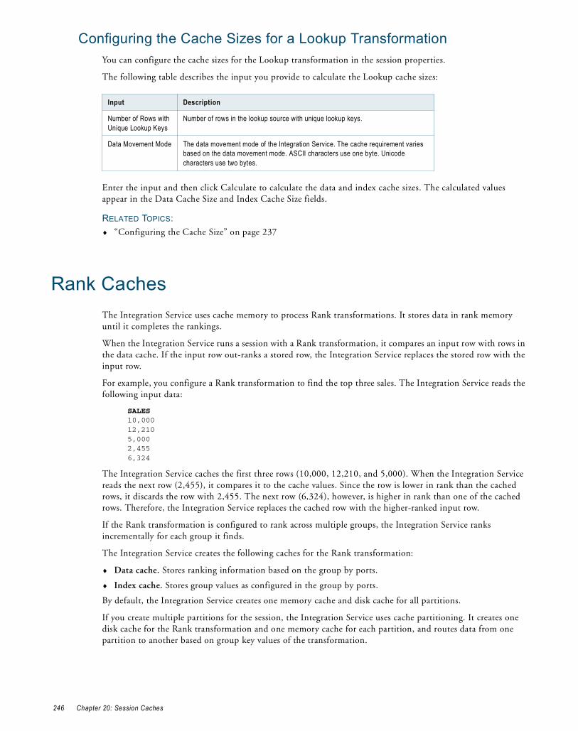
Configuring the Cache Sizes for a Lookup TransformationYou can configure the cache sizes for the Lookup transformation in the session properties.
The following table describes the input you provide to calculate the Lookup cache sizes:
Enter the input and then click Calculate to calculate the data and index cache sizes. The calculated values appear in the Data Cache Size and Index Cache Size fields.
RELATED TOPICS:♦ “Configuring the Cache Size” on page 237
Rank CachesThe Integration Service uses cache memory to process Rank transformations. It stores data in rank memory until it completes the rankings.
When the Integration Service runs a session with a Rank transformation, it compares an input row with rows in the data cache. If the input row out-ranks a stored row, the Integration Service replaces the stored row with the input row.
For example, you configure a Rank transformation to find the top three sales. The Integration Service reads the following input data:
SALES 10,00012,2105,0002,4556,324
The Integration Service caches the first three rows (10,000, 12,210, and 5,000). When the Integration Service reads the next row (2,455), it compares it to the cache values. Since the row is lower in rank than the cached rows, it discards the row with 2,455. The next row (6,324), however, is higher in rank than one of the cached rows. Therefore, the Integration Service replaces the cached row with the higher-ranked input row.
If the Rank transformation is configured to rank across multiple groups, the Integration Service ranks incrementally for each group it finds.
The Integration Service creates the following caches for the Rank transformation:
♦ Data cache. Stores ranking information based on the group by ports.
♦ Index cache. Stores group values as configured in the group by ports.
By default, the Integration Service creates one memory cache and disk cache for all partitions.
If you create multiple partitions for the session, the Integration Service uses cache partitioning. It creates one disk cache for the Rank transformation and one memory cache for each partition, and routes data from one partition to another based on group key values of the transformation.
Input Description
Number of Rows with Unique Lookup Keys
Number of rows in the lookup source with unique lookup keys.
Data Movement Mode The data movement mode of the Integration Service. The cache requirement varies based on the data movement mode. ASCII characters use one byte. Unicode characters use two bytes.
246 Chapter 20: Session Caches
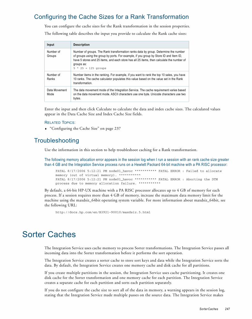
Configuring the Cache Sizes for a Rank TransformationYou can configure the cache sizes for the Rank transformation in the session properties.
The following table describes the input you provide to calculate the Rank cache sizes:
Enter the input and then click Calculate to calculate the data and index cache sizes. The calculated values appear in the Data Cache Size and Index Cache Size fields.
RELATED TOPICS:♦ “Configuring the Cache Size” on page 237
TroubleshootingUse the information in this section to help troubleshoot caching for a Rank transformation.
The following memory allocation error appears in the session log when I run a session with an rank cache size greater than 4 GB and the Integration Service process runs on a Hewlett Packard 64-bit machine with a PA RISC processor:
FATAL 8/17/2006 5:12:21 PM node01_havoc *********** FATAL ERROR : Failed to allocate memory (out of virtual memory). ***********FATAL 8/17/2006 5:12:21 PM node01_havoc *********** FATAL ERROR : Aborting the DTM process due to memory allocation failure. ***********
By default, a 64-bit HP-UX machine with a PA RISC processor allocates up to 4 GB of memory for each process. If a session requires more than 4 GB of memory, increase the maximum data memory limit for the machine using the maxdsiz_64bit operating system variable. For more information about maxdsiz_64bit, see the following URL:
http://docs.hp.com/en/B3921-90010/maxdsiz.5.html
Sorter CachesThe Integration Service uses cache memory to process Sorter transformations. The Integration Service passes all incoming data into the Sorter transformation before it performs the sort operation.
The Integration Service creates a sorter cache to store sort keys and data while the Integration Service sorts the data. By default, the Integration Service creates one memory cache and disk cache for all partitions.
If you create multiple partitions in the session, the Integration Service uses cache partitioning. It creates one disk cache for the Sorter transformation and one memory cache for each partition. The Integration Service creates a separate cache for each partition and sorts each partition separately.
If you do not configure the cache size to sort all of the data in memory, a warning appears in the session log, stating that the Integration Service made multiple passes on the source data. The Integration Service makes
Input Description
Number of Groups
Number of groups. The Rank transformation ranks data by group. Determine the number of groups using the group by ports. For example, if you group by Store ID and Item ID, have 5 stores and 25 items, and each store has all 25 items, then calculate the number of groups as:5 * 25 = 125 groups
Number of Ranks
Number items in the ranking. For example, if you want to rank the top 10 sales, you have 10 ranks. The cache calculator populates this value based on the value set in the Rank transformation.
Data Movement Mode
The data movement mode of the Integration Service. The cache requirement varies based on the data movement mode. ASCII characters use one byte. Unicode characters use two bytes.
Sorter Caches 247

multiple passes on the data when it has to page information to disk to complete the sort. The message specifies the number of bytes required for a single pass, which is when the Integration Service reads the data once and performs the sort in memory without paging to disk. To increase session performance, configure the cache size so that the Integration Service makes one pass on the data.
Configuring the Cache Size for a Sorter TransformationYou can configure the sorter cache for a Sorter transformation in the session properties.
The following table describes the input you provide to calculate the Sorter cache size:
Enter the input and then click Calculate to calculate the sorter cache size. The calculated value appears in the Sorter Cache Size field.
RELATED TOPICS:♦ “Configuring the Cache Size” on page 237
XML Target CachesThe Integration Service uses cache memory to create an XML target. The Integration Service stores the data and XML hierarchies in cache memory while it generates the XML target.
The Integration Service creates the following types of caches for an XML target:
♦ Data cache. Stores XML row data while it generates an XML target document. Stores one data cache for all groups.
♦ Index caches. Stores primary keys or foreign keys. Creates a primary key index cache and a foreign key index cache for each group.
Configuring the Cache Size for an XML TargetYou configure the cache size for an XML target in the target or session properties. By default, cache size is set to “auto.” The Integration Service determines the required amount of cache memory at run-time.
You can also configure the cache size and specify the amount of cache memory in bytes. Complete the following steps to calculate the cache size:
1. Estimate the number of rows in each group.
2. Use the following formula to calculate the cache size for each group:
Group cache size = Data cache size + Primary key index cache size + Foreign key index cache size
3. Use the following formula to calculate the total cache size:
Total cache size = Σ(Cache size of all groups)
Input Description
Number of Rows Number of rows.
Data Movement Mode
The data movement mode of the Integration Service. The cache requirement varies based on the data movement mode. ASCII characters use one byte. Unicode characters use two bytes.
248 Chapter 20: Session Caches

The following table shows how to calculate the size of the data cache and trees for a group:
Note: You cannot use the cache calculator to configure the cache size for an XML target.
Optimizing the Cache SizeFor optimal session performance, configure the cache size so that the Integration Service processes the transformation in memory without paging to disk. Session performance decreases when the Integration Service pages to disk.
When you use the cache calculator to calculate the cache size, the cache calculator estimates the cache size required for optimal session performance based on your input. You can tune the estimate by using the cache size specified in the session log. After you run the session, review the transformation statistics in the session log to get the cache size.
For example, you run an Aggregator transformation called AGGTRANS. The session log contains the following text:
MAPPING> TT_11031 Transformation [AGGTRANS]:MAPPING> TT_11114 [AGGTRANS]: Input Group Index = [0], Input Row Count [110264]MAPPING> TT_11034 [SQ_V_PETL]: Input - 110264MAPPING> TT_11115 [AGGTRANS]: Output Group Index = [0]MAPPING> TT_11037 [FILTRANS]: Output - 1098,Dropped - 0MAPPING> CMN_1791 The index cache size that would hold [1098] aggregate groups of input rows for [AGGTRANS], in memory, is [286720] bytesMAPPING> CMN_1790 The data cache size that would hold [1098] aggregate groups of input rows for [AGGTRANS], in memory, is [1774368] bytes
The log shows that the index cache requires 286,720 bytes and the data cache requires 1,774,368 bytes to process the transformation in memory without paging to disk.
The cache size may vary depending on changes to the session or source data. Review the session logs after subsequent session runs to monitor changes to the cache size.
You must set the tracing level to Verbose Initialization in the session properties to enable the Integration Service to write the transformation statistics to the session log.
Note: The session log does not contain transformation statistics for a Sorter, a Joiner transformation with sorted input, an Aggregator transformation with sorted input, or an XML target.
Data Cache = (Number of rows in a group) X (Row size of the group)
Primary Key Tree Size = (Number of rows in a group) X (Primary key index cache size)
Foreign Key Tree Size = Σ ((Number of rows in parent group) X (Foreign key index cache size))
Optimizing the Cache Size 249

250 Chapter 20: Session Caches

C H A P T E R 2 1
Incremental Aggregation
This chapter includes the following topics:
♦ Overview, 251
♦ Integration Service Processing for Incremental Aggregation, 252
♦ Reinitializing the Aggregate Files, 252
♦ Moving or Deleting the Aggregate Files, 253
♦ Partitioning Guidelines with Incremental Aggregation, 253
♦ Preparing for Incremental Aggregation, 254
OverviewWhen using incremental aggregation, you apply captured changes in the source to aggregate calculations in a session. If the source changes incrementally and you can capture changes, you can configure the session to process those changes. This allows the Integration Service to update the target incrementally, rather than forcing it to process the entire source and recalculate the same data each time you run the session.
For example, you might have a session using a source that receives new data every day. You can capture those incremental changes because you have added a filter condition to the mapping that removes pre-existing data from the flow of data. You then enable incremental aggregation.
When the session runs with incremental aggregation enabled for the first time on March 1, you use the entire source. This allows the Integration Service to read and store the necessary aggregate data. On March 2, when you run the session again, you filter out all the records except those time-stamped March 2. The Integration Service then processes the new data and updates the target accordingly.
Consider using incremental aggregation in the following circumstances:
♦ You can capture new source data. Use incremental aggregation when you can capture new source data each time you run the session. Use a Stored Procedure or Filter transformation to process new data.
♦ Incremental changes do not significantly change the target. Use incremental aggregation when the changes do not significantly change the target. If processing the incrementally changed source alters more than half the existing target, the session may not benefit from using incremental aggregation. In this case, drop the table and recreate the target with complete source data.
Note: Do not use incremental aggregation if the mapping contains percentile or median functions. The Integration Service uses system memory to process these functions in addition to the cache memory you configure in the session properties. As a result, the Integration Service does not store incremental aggregation values for percentile and median functions in disk caches.
251

Integration Service Processing for Incremental Aggregation
The first time you run an incremental aggregation session, the Integration Service processes the entire source. At the end of the session, the Integration Service stores aggregate data from that session run in two files, the index file and the data file. The Integration Service creates the files in the cache directory specified in the Aggregator transformation properties.
Each subsequent time you run the session with incremental aggregation, you use the incremental source changes in the session. For each input record, the Integration Service checks historical information in the index file for a corresponding group. If it finds a corresponding group, the Integration Service performs the aggregate operation incrementally, using the aggregate data for that group, and saves the incremental change. If it does not find a corresponding group, the Integration Service creates a new group and saves the record data.
When writing to the target, the Integration Service applies the changes to the existing target. It saves modified aggregate data in the index and data files to be used as historical data the next time you run the session.
If the source changes significantly and you want the Integration Service to continue saving aggregate data for future incremental changes, configure the Integration Service to overwrite existing aggregate data with new aggregate data.
Each subsequent time you run a session with incremental aggregation, the Integration Service creates a backup of the incremental aggregation files. The cache directory for the Aggregator transformation must contain enough disk space for two sets of the files.
When you partition a session that uses incremental aggregation, the Integration Service creates one set of cache files for each partition.
The Integration Service creates new aggregate data, instead of using historical data, when you perform one of the following tasks:
♦ Save a new version of the mapping.
♦ Configure the session to reinitialize the aggregate cache.
♦ Move the aggregate files without correcting the configured path or directory for the files in the session properties.
♦ Change the configured path or directory for the aggregate files without moving the files to the new location.
♦ Delete cache files.
♦ Decrease the number of partitions.
When the Integration Service rebuilds incremental aggregation files, the data in the previous files is lost.
Note: To protect the incremental aggregation files from file corruption or disk failure, periodically back up the files.
Reinitializing the Aggregate FilesIf the source tables change significantly, you might want the Integration Service to create new aggregate data, instead of using historical data. To have the Integration Service create new aggregate data, configure the session to reinitialize the aggregate cache.
For example, you can reinitialize the aggregate cache if the source for a session changes incrementally every day and completely changes once a month. When you receive the new source data for the month, you might configure the session to reinitialize the aggregate cache, truncate the existing target, and use the new source table during the session.
252 Chapter 21: Incremental Aggregation
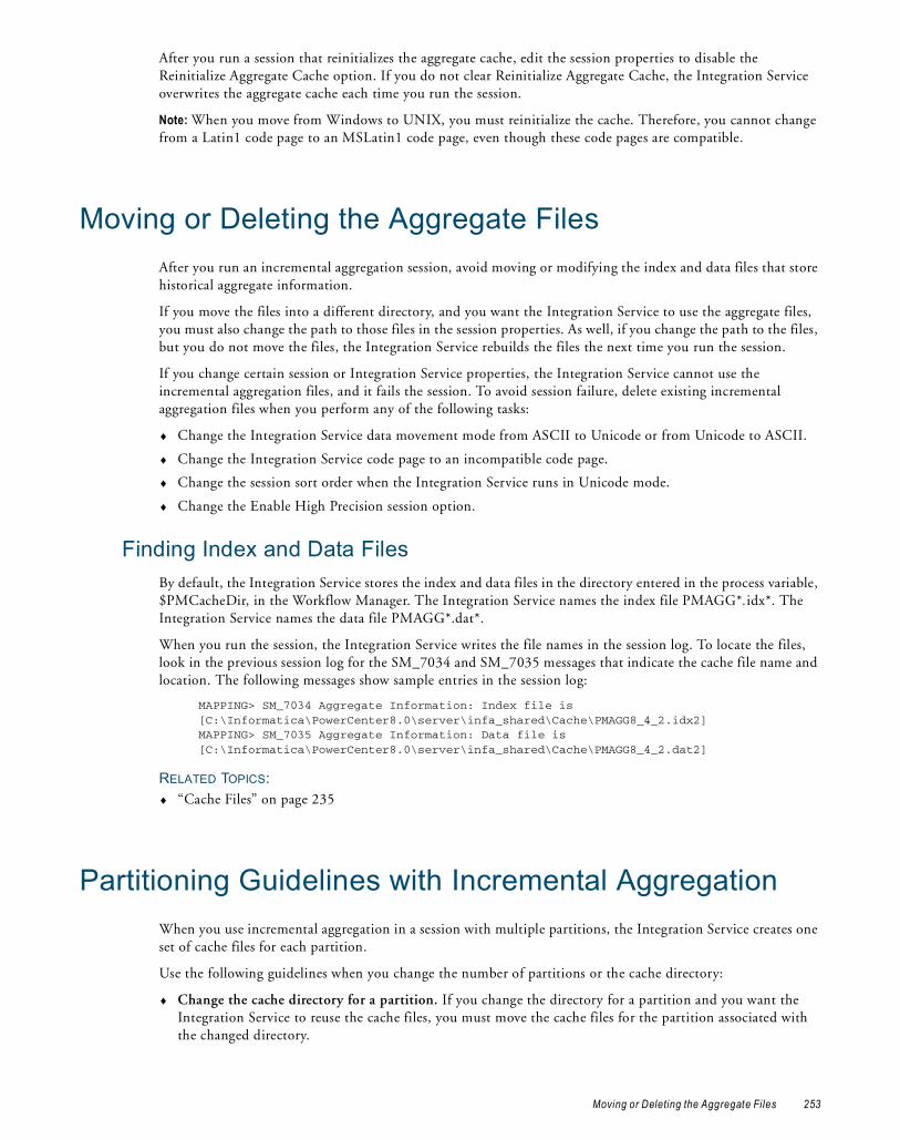
After you run a session that reinitializes the aggregate cache, edit the session properties to disable the Reinitialize Aggregate Cache option. If you do not clear Reinitialize Aggregate Cache, the Integration Service overwrites the aggregate cache each time you run the session.
Note: When you move from Windows to UNIX, you must reinitialize the cache. Therefore, you cannot change from a Latin1 code page to an MSLatin1 code page, even though these code pages are compatible.
Moving or Deleting the Aggregate FilesAfter you run an incremental aggregation session, avoid moving or modifying the index and data files that store historical aggregate information.
If you move the files into a different directory, and you want the Integration Service to use the aggregate files, you must also change the path to those files in the session properties. As well, if you change the path to the files, but you do not move the files, the Integration Service rebuilds the files the next time you run the session.
If you change certain session or Integration Service properties, the Integration Service cannot use the incremental aggregation files, and it fails the session. To avoid session failure, delete existing incremental aggregation files when you perform any of the following tasks:
♦ Change the Integration Service data movement mode from ASCII to Unicode or from Unicode to ASCII.
♦ Change the Integration Service code page to an incompatible code page.
♦ Change the session sort order when the Integration Service runs in Unicode mode.
♦ Change the Enable High Precision session option.
Finding Index and Data FilesBy default, the Integration Service stores the index and data files in the directory entered in the process variable, $PMCacheDir, in the Workflow Manager. The Integration Service names the index file PMAGG*.idx*. The Integration Service names the data file PMAGG*.dat*.
When you run the session, the Integration Service writes the file names in the session log. To locate the files, look in the previous session log for the SM_7034 and SM_7035 messages that indicate the cache file name and location. The following messages show sample entries in the session log:
MAPPING> SM_7034 Aggregate Information: Index file is [C:\Informatica\PowerCenter8.0\server\infa_shared\Cache\PMAGG8_4_2.idx2]MAPPING> SM_7035 Aggregate Information: Data file is [C:\Informatica\PowerCenter8.0\server\infa_shared\Cache\PMAGG8_4_2.dat2]
RELATED TOPICS:♦ “Cache Files” on page 235
Partitioning Guidelines with Incremental AggregationWhen you use incremental aggregation in a session with multiple partitions, the Integration Service creates one set of cache files for each partition.
Use the following guidelines when you change the number of partitions or the cache directory:
♦ Change the cache directory for a partition. If you change the directory for a partition and you want the Integration Service to reuse the cache files, you must move the cache files for the partition associated with the changed directory.
Moving or Deleting the Aggregate Files 253
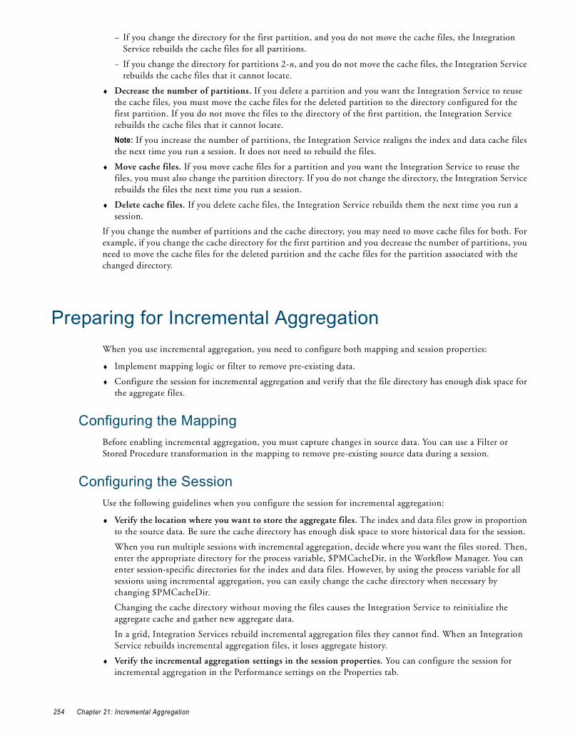
− If you change the directory for the first partition, and you do not move the cache files, the Integration Service rebuilds the cache files for all partitions.
− If you change the directory for partitions 2-n, and you do not move the cache files, the Integration Service rebuilds the cache files that it cannot locate.
♦ Decrease the number of partitions. If you delete a partition and you want the Integration Service to reuse the cache files, you must move the cache files for the deleted partition to the directory configured for the first partition. If you do not move the files to the directory of the first partition, the Integration Service rebuilds the cache files that it cannot locate.
Note: If you increase the number of partitions, the Integration Service realigns the index and data cache files the next time you run a session. It does not need to rebuild the files.
♦ Move cache files. If you move cache files for a partition and you want the Integration Service to reuse the files, you must also change the partition directory. If you do not change the directory, the Integration Service rebuilds the files the next time you run a session.
♦ Delete cache files. If you delete cache files, the Integration Service rebuilds them the next time you run a session.
If you change the number of partitions and the cache directory, you may need to move cache files for both. For example, if you change the cache directory for the first partition and you decrease the number of partitions, you need to move the cache files for the deleted partition and the cache files for the partition associated with the changed directory.
Preparing for Incremental AggregationWhen you use incremental aggregation, you need to configure both mapping and session properties:
♦ Implement mapping logic or filter to remove pre-existing data.
♦ Configure the session for incremental aggregation and verify that the file directory has enough disk space for the aggregate files.
Configuring the MappingBefore enabling incremental aggregation, you must capture changes in source data. You can use a Filter or Stored Procedure transformation in the mapping to remove pre-existing source data during a session.
Configuring the SessionUse the following guidelines when you configure the session for incremental aggregation:
♦ Verify the location where you want to store the aggregate files. The index and data files grow in proportion to the source data. Be sure the cache directory has enough disk space to store historical data for the session.
When you run multiple sessions with incremental aggregation, decide where you want the files stored. Then, enter the appropriate directory for the process variable, $PMCacheDir, in the Workflow Manager. You can enter session-specific directories for the index and data files. However, by using the process variable for all sessions using incremental aggregation, you can easily change the cache directory when necessary by changing $PMCacheDir.
Changing the cache directory without moving the files causes the Integration Service to reinitialize the aggregate cache and gather new aggregate data.
In a grid, Integration Services rebuild incremental aggregation files they cannot find. When an Integration Service rebuilds incremental aggregation files, it loses aggregate history.
♦ Verify the incremental aggregation settings in the session properties. You can configure the session for incremental aggregation in the Performance settings on the Properties tab.
254 Chapter 21: Incremental Aggregation

You can also configure the session to reinitialize the aggregate cache. If you choose to reinitialize the cache, the Workflow Manager displays a warning indicating the Integration Service overwrites the existing cache and a reminder to clear this option after running the session.
Note: You cannot use incremental aggregation when the mapping includes an Aggregator transformation with Transaction transformation scope. The Workflow Manager marks the session invalid.
Preparing for Incremental Aggregation 255

256 Chapter 21: Incremental Aggregation

C H A P T E R 2 2
Session Log Interface
This chapter includes the following topics:
♦ Overview, 257
♦ Implementing the Session Log Interface, 257
♦ Functions in the Session Log Interface, 258
♦ Session Log Interface Example, 261
OverviewBy default, the Integration Service writes session events to binary log files on the node where the service process runs. In addition, the Integration Service can pass the session event information to an external library. In the external shared library, you can provide the procedure for how the Integration Service writes the log events.
PowerCenter provides access to the session event information through the Session Log Interface. When you create the shared library, you implement the functions provided in the Session Log Interface.
When the Integration Service writes the session events, it calls the functions specified in the Session Log Interface. The functions in the shared library you create must match the function signatures defined in the Session Log Interface.
Implementing the Session Log InterfaceTo configure the Integration Service to use a custom procedure for handling session event information, complete the following steps:
1. Create a shared library that implements the Session Log Interface.
2. When you configure the Integration Service properties on the Administration Console, set the ExportSessionLogLibName property to the name of the shared library that you create.
The Integration Service and the Session Log InterfaceWhen you set the ExportSessionLogLibName property of the Integration Service to the name of a shared library, the Integration Service performs the procedures defined in the shared library in addition to creating the event log files.
The Integration Service uses the shared library in the following manner:
Overview 257

1. The Integration Service loads the shared library and calls the INFA_InitSessionLog() function before it logs the first event in the session.
2. Each time the Integration Service logs an event to the session log file, it calls the INFA_OutputSessionLog() function to pass the message, codes, and session information to the shared library.
3. When the session completes and the last event is logged, the Integration Service calls the INFA_EndSessionLog() and then unloads the shared library.
To ensure that the shared library can be correctly called by the Integration Service, follow the guidelines for writing the shared library.
Rules and Guidelines for Implementing the Session Log InterfaceUse the following rules and guidelines when you write the code to implement the Session Log Interface:
♦ You must implement all the functions in the Session Log Interface.
♦ All calls from the Integration Service to the functions in the Session Log Interface are serialized except for abnormal termination. The Integration Service makes the calls to the functions as it logs events to the session log. Therefore, when you implement the functions in the Session Log Interface, you do not need to use mutex objects to ensure that only one thread executes a section of code at a time.
♦ When you implement the Session Log Interface in UNIX, do not perform any signal handling within the functions. This ensures that the functions do not interfere with the way that PowerCenter handles signals. Do not register or unregister any signal handlers.
♦ Since the Integration Service is a multi-threaded process, you must compile the shared library as a multi-threaded library so that it can be loaded correctly.
Functions in the Session Log InterfaceThe functions in the Session Log Interface do not return values. Therefore, a session cannot fail because of an Integration Service call to a function in the Session Log Interface.
The following table describes the functions in the Session Log Interface:
The functions described in this section use the time structures declared in the standard C header file time.h. The functions also assume the following declarations:
typedef int INFA_INT32; typedef unsigned int INFA_UINT32; typedef unsigned short INFA_UNICHAR; typedef char INFA_MBCSCHAR; typedef int INFA_MBCS_CODEPAGE_ID;
Function Description
INFA_InitSessionLog Provides information about the session for which the Integration Service will write the event logs.
INFA_OutputSessionLogMsg Called each time an event is logged. Passes the information about the event.
INFA_OutputSessionLogFatalMsg Called when the last event is logged before an abnormal termination.
INFA_EndSessionLog Called after the last message is sent to the session log and the session terminates normally.
INFA_AbnormalSessionTermination Called after the last message is sent to the session log and the session terminates abnormally.
258 Chapter 22: Session Log Interface

INFA_InitSessionLogvoid INFA_InitSessionLog(void ** dllContext, const INFA_UNICHAR * sServerName, const INFA_UNICHAR * sFolderName, const INFA_UNICHAR * sWorkflowName, const INFA_UNICHAR * sessionHierName[]);
The Integration Service calls the INFA_InitSessionLog function before it writes any session log event. The parameters passed to this function provide information about the session for which the Integration Service will write the event logs.
INFA_InitSessionLog has the following parameters:
INFA_OutputSessionLogMsgvoid INFA_OutputSessionLogMsg( void * dllContext, time_t curTime, INFA_UINT32 severity, const INFA_UNICHAR * msgCategoryName, INFA_UINT32 msgCode, const INFA_UNICHAR * msg, const INFA_UNICHAR * threadDescription);
The Integration Service calls this function each time it logs an event. The parameters passed to the function include the different elements of the log event message. You can use the parameters to customize the format for the log output or to filter out messages.
INFA_OutputSessionLogMsg has the following parameters:
Parameter Data Type Description
dllContext Unspecified User-defined information specific to the shared library. This parameter is passed to all functions in subsequent function calls. You can use this parameter to store information related to network connection or to allocate memory needed during the course of handling the session log output. The shared library must allocate and deallocate any memory associated with this parameter.
sServerName unsigned short Name of the Integration Service running the session.
sFolderName unsigned short Name of the folder that contains the session.
sWorkflowName unsigned short Name of the workflow associated with the session
sessionHierName[] unsigned short array
Array that contains the session hierarchy. The array includes the repository, workflow, and worklet (if any) to which the session belongs. The size of the array divided by the size of the pointer equals the number of array elements.
Parameter Data Type Description
dllContext Unspecified User-defined information specific to the shared library. You can use this parameter to store information related to network connection or to allocate memory needed during the course of handling the session log output. The shared library must allocate and deallocate any memory associated with this parameter.
curTime time_t Time that the Integration Service logs the event.
severity unsigned int Code that indicates the type of the log event message. The event logs use the following severity codes:32: Debug Messages 8: Informational Messages 2: Error Messages
Functions in the Session Log Interface 259

INFA_OutputSessionLogFatalMsgvoid INFA_OutputSessionLogFatalMsg(void * dllContext, const char * msg);
The Integration Service calls this function to log the last event before an abnormal termination. The parameter msg is MBCS characters in the Integration Service code page.
When you implement this function in UNIX, make sure that you call only asynchronous signal safe functions from within this function.
INFA_OutputSessionLogFatalMsg has the following parameters:
INFA_EndSessionLogvoid INFA_EndSessionLog(void * dllContext);
The Integration Service calls this function after the last message is sent to the session log and the session terminates normally. You can use this function to perform clean up operations and release memory and resources.
INFA_EndSessionLog has the following parameter:
msgCategoryName constant unsigned short
Code prefix that indicates the category of the log event message.In the following example message, the string BLKR is the value passed in the msgCategoryName parameter.READER_1_1_1> BLKR_16003 Initialization completed successfully.
msgCode unsigned int Number that identifies the log event message.In the following example message, the string 16003 is the value passed in the msgCode parameter.READER_1_1_1> BLKR_16003 Initialization completed successfully.
msg constant unsigned short
Text of the log event message. In the following example message, the string Initialization completed successfully is the value passed in the msg parameter.READER_1_1_1> BLKR_16003 Initialization completed successfully.
threadDescription constant unsigned short
Code that indicates which thread is generating the event log.In the following example message, the string READER_1_1_1 is the value passed in the threadDescription parameter.READER_1_1_1> BLKR_16003 Initialization completed successfully.
Parameter Data Type Description
dllContext Unspecified User-defined information specific to the shared library. You can use this parameter to store information related to network connection or to allocate memory needed during the course of handling the session log output. The shared library must allocate and deallocate any memory associated with this parameter.
msg constant char Text of the error message. Typically, these messages are assertion error messages or operating system error messages.
Parameter Data Type Description
dllContext Unspecified User-defined information specific to the shared library. You can use this parameter to store information related to network connection or to allocate memory needed during the course of handling the session log output. The shared library must allocate and deallocate any memory associated with this parameter.
Parameter Data Type Description
260 Chapter 22: Session Log Interface

INFA_AbnormalSessionTerminationvoid INFA_AbnormalSessionTermination(void * dllContext);
The Integration Service calls this function after the last message is sent to the session log and the session terminates abnormally. The Integration Service calls this function after it calls the INFA_OutputSessionLogFatalMsg function. If the Integration Service calls this function, then it does not call INFA_EndSessionLog.
For example, the Integration Service calls this function when the DTM aborts or times out. In UNIX, the Integration Service calls this function when a signal exception occurs.
Include only minimal functionality when you implement this function. In UNIX, make sure that you call only asynchronous signal safe functions from within this function.
INFA_AbnormalSessionTermination has the following parameter:
Session Log Interface ExampleInformatica provides a sample program that uses the Session Log Interface. The sample program sends session log events to a text file called sesslog.log. You can view the sample program to gain more understanding about how to use the Session Log Interface to handle session log events based on your requirements. You can also compile the sample program and build an external library to send session log events to a text file.
The session log sample program is available when you install the PowerCenter SDK files from the Informatica Development Platform installer. By default, the session log sample program is installed in the following directory:
<SDKInstallationDir>/SessionLog_API/samples
Building the External Session Log LibraryUse the make files provided with the sample program demo_sesslog.cpp to build the external library. The command to compile the library depends on the platform on which you build it.
Building the Library in UNIXThe following table shows the command to build the library on the different platforms:
Parameter Data Type Description
dllContext Unspecified User-defined information specific to the shared library. You can use this parameter to store information related to network connection or to allocate memory needed during the course of handling the session log output. The shared library must allocate and deallocate any memory associated with this parameter.
Platform Compiler Command
Solaris CC make -f makefile_sol
HP-UX aCC make -f makefile_hpux
HP-UX 64 bit aCC make -f makefile_hpux64
AIX xCl_r make -f makefile_aix
AIX 64 bit xCl_r make -f makefile_aix64
Linux g++ make -f makefile_linux
Session Log Interface Example 261

Building the Library in WindowsUse Microsoft Visual C++ 6.0 to build the sample session log library in Windows. Open the sample program demo_sesslog.dsw in Visual C++ 6.0 and build the project.
Using the External Session Log LibraryAfter you build the library, you can use it to write the output of the session log into a file.
To use the sample external session log library, complete the following steps:
1. Log in to the Administration Console and select the Integration Service for which you want to set up the session log file.
2. On the Properties tab of the Integration Service, edit the configuration properties.
3. Set the ExportSessionLogLibName property to the path and file name of the session log library you created from the session log sample program.
262 Chapter 22: Session Log Interface

C H A P T E R 2 3
Understanding Buffer Memory
This chapter includes the following topics:
♦ Overview, 263
♦ Configuring Automatic Memory Settings, 264
♦ Configuring Buffer Memory, 265
♦ Configuring Session Cache Memory, 265
OverviewWhen you run a session, the Integration Service process starts the Data Transformation Manager (DTM). The DTM allocates buffer memory to the session at run time based on the DTM Buffer Size setting in the session properties.
The DTM divides the memory into buffer blocks as configured in the Default Buffer Block Size setting in the session properties. The reader, transformation, and writer threads use buffer blocks to move data from sources to targets. The buffer block size should be larger than the precision for the largest row of data in a source or target.
The Integration Service allocates at least two buffer blocks for each source and target partition. Use the following calculation to determine buffer block requirements:
[(total number of sources + total number of targets)* 2] = (session buffer blocks)
For example, a session that contains a single partition using a mapping that contains 50 sources and 50 targets requires a minimum of 200 buffer blocks.
[(50 + 50)* 2] = 200
You configure buffer memory settings by adjusting the following session properties:
♦ DTM Buffer Size. The DTM buffer size specifies the amount of buffer memory the Integration Service uses when the DTM processes a session. Configure the DTM buffer size on the Properties tab in the session properties.
♦ Default Buffer Block Size. The buffer block size specifies the amount of buffer memory used to move a block of data from the source to the target. Configure the buffer block size on the Config Object tab in the session properties.
The Integration Service specifies a minimum memory allocation for the buffer memory and buffer blocks. By default, the Integration Service allocates 12,000,000 bytes of memory to the buffer memory and 64,000 bytes per block.
263

If the DTM cannot allocate the configured amount of buffer memory for the session, the session cannot initialize. Usually, you do not need more than 1 GB for the buffer memory.
You can configure a numeric value for the buffer size, or you can configure the session to determine the buffer memory size at run time.
Configuring Automatic Memory SettingsYou can configure the Integration Service to determine buffer memory size and session cache size at run time. When you run a session, the Integration Service allocates buffer memory to the session to move the data from the source to the first transformation and from the last transformation to the target. It also creates session caches in memory. Session caches include index and data caches for the Aggregator, Rank, Joiner, and Lookup transformations. The values stored in the data and index caches depend on the requirements of the transformation. For example, the Aggregator index cache stores group values as configured in the group by ports, and the data cache stores calculations based on the group by ports. When the Integration Service processes a Sorter transformation or writes data to an XML target, it also creates a cache.
Configure buffer memory and cache memory settings in the transformation and session properties. When you configure buffer memory and cache memory settings, consider the overall memory usage for best performance.
You enable automatic memory settings by configuring a value for the Maximum Memory Allowed for Auto Memory Attributes and the Maximum Percentage of Total Memory Allowed for Auto Memory Attributes. If you set either of these properties to zero, the Integration Service uses default values for memory attributes that you set to auto.
RELATED TOPICS:♦ “Overview” on page 233
Configuring Automatic Memory Settings for Multiple SessionsYou can configure automatic memory settings for multiple sessions using session configuration objects. Configure automatic memory settings in the session configuration object when you migrate from a test to a production environment or when you have multiple sessions with different automatic memory requirements.
Configure automatic memory settings in the default session configuration object when you want to migrate sessions from a test environment to a production environment.
The following table shows an example of the automatic memory settings you might want to configure:
When you create sessions in the test environment, set the Maximum Memory Allowed for Auto Memory Attributes to 50 MB and the Maximum Percentage of Total Memory Allowed for Auto Memory Attributes to 2% in the default session configuration object. In the production environment, set the automatic memory settings to 500 MB and 5% in the default session configuration object. In each environment, the Integration Service uses the values in the default session configuration object.
Use different session configuration objects when you have sessions with different memory requirements. For example, most sessions you run require 1 GB of memory, but a few large sessions require 4 GB of memory. In the default session configuration object, set Maximum Memory Allowed for Auto Memory Attributes to 1 GB.
Automatic Memory Setting Test Environ-ment
Production Environment
Maximum Memory Allowed for Auto Memory Attributes 50 MB 500 MB
Maximum Percentage of Total Memory Allowed for Auto Memory Attributes
2% 5%
264 Chapter 23: Understanding Buffer Memory

Create another session configuration object and set Maximum Memory Allowed for Auto Memory Attributes to 4 GB. Use this session configuration object for the large memory sessions.
For more information about session configuration objects, see the PowerCenter Workflow Basics Guide.
Configuring Buffer MemoryThe Integration Service can determine the memory requirements for the following buffer memory:
♦ DTM Buffer Size
♦ Default Buffer Block Size
You can configure DTM buffer size and the default buffer block size in the session properties. If you specify a numeric value that is less than 12MB for the DTM buffer size, the Integration Service updates the DTM buffer size to 12MB. When the session requires more memory than the value you configure for the DTM buffer size, session performance decreases and the session can fail.
If the session is configured to retry on deadlock and the value for the DTM buffer size is less than what the session requires, the Integration Service writes the following message in the session log:
WRT_8193 Deadlock retry will not be used. The free buffer pool must be at least [number of bytes] bytes. The current size of the free buffer pool is [number of bytes] bytes.
To configure automatic memory settings for the DTM buffer size:
1. Open the session, and click the Config Object tab.
2. Enter a value for the Default Buffer Block Size.
You can specify auto or a numeric value. If you enter 2000, the Integration Service interprets the number as 2,000 bytes. Append KB, MB, or GB to the value to specify other units. For example, specify 512MB.
3. Click the Properties tab.
4. Enter a value for the DTM buffer size.
You can specify auto or a numeric value. If you enter 2000, the Integration Service interprets the number as 2,000 bytes. Append KB, MB, or GB to the value to specify other units. For example, specify 512MB.
Note: If you specify auto for the DTM buffer size or the default Buffer Block Size, enable automatic memory settings by configuring a non-zero value for the Maximum Memory Allowed for Auto Memory Attributes and the Maximum Percentage of Total Memory Allowed for Auto Memory Attributes. If you do not enable automatic memory settings after you specify auto for the DTM buffer size or the default Buffer Block Size, the Integration Service uses default values.
Configuring Session Cache MemoryThe Integration Service can determine memory requirements for the following session caches:
♦ Lookup transformation index and data caches
♦ Aggregator transformation index and data caches
♦ Rank transformation index and data caches
♦ Joiner transformation index and data caches
♦ Sorter transformation cache
♦ XML target cache
Configuring Buffer Memory 265

You can configure auto for the index and data cache size in the transformation properties or on the mappings tab of the session properties.
Configuring Maximum Memory LimitsWhen you configure automatic memory settings for session caches, configure the maximum memory limits. Configuring memory limits allows you to ensure that you reserve a designated amount or percentage of memory for other processes. You can configure the memory limit as a numeric value and as a percent of total memory. Because available memory varies, the Integration Service bases the percentage value on the total memory on the Integration Service process machine.
For example, configure automatic caching for three Lookup transformations in a session. Then, configure a maximum memory limit of 500 MB for the session. When you run the session, the Integration Service divides the 500 MB of allocated memory among the index and data caches for the Lookup transformations. The maximum memory limit for the session does not apply to transformations that you did not configure for automatic cashing.
When you configure a maximum memory value, the Integration Service divides memory among transformation caches based on the transformation type.
When you configure a maximum memory, you must specify the value as both a numeric value and a percentage. When you configure a numeric value and a percent, the Integration Service compares the values and determines which value is lower. The Integration Service uses the lesser of these values as the maximum memory limit.
When you configure automatic memory settings, the Integration Service specifies a minimum memory allocation for the index and data caches. By default, the Integration Service allocates 1megabyte to the index cache and 2 megabytes to the data cache for each transformation instance. If you configure a maximum memory limit that is less than the minimum value for an index or data cache, the Integration Service overrides the value based on the transformation metadata.
When you run a session on a grid and you configure Maximum Memory Allowed For Auto Memory Attributes, the Integration Service divides the allocated memory among all the nodes in the grid. When you configure Maximum Percentage of Total Memory Allowed For Auto Memory Attributes, the Integration Service allocates the specified percentage of memory on each node in the grid.
Configuring Automatic Memory Settings for Session CachesTo use automatic memory settings for session caches, configure the caches for auto and configure the maximum memory size.
To configure automatic memory settings for session caches:
1. Open the transformation in the Transformation Developer or the Mappings tab of the session properties.
2. In the transformation properties, select or enter auto for the following cache size settings:
♦ Index and data cache
♦ Sorter cache
♦ XML cache
3. Open the session in the Task Developer or Workflow Designer, and click the Config Object tab.
4. Enter a value for the Maximum Memory Allowed for Auto Memory Attributes.
If you enter 2000, the Integration Service interprets the number as 2,000 bytes. Append KB, MB, or GB to the value to specify other units. For example, specify 512MB. This value specifies the maximum amount of memory to use for session caches. If you set the value to zero, the Integration Service uses default values for memory attributes that you set to auto.
5. Enter a value for the Maximum Percentage of Total Memory Allowed for Auto Memory Attributes.
This value specifies the maximum percentage of total memory the session caches may use. If the value is set to zero, the Integration Service uses default values for memory attributes that you set to auto.
266 Chapter 23: Understanding Buffer Memory
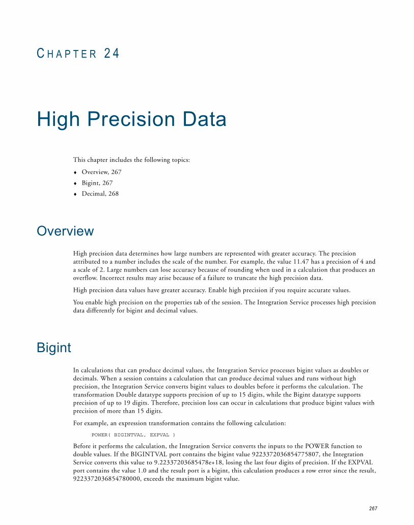
C H A P T E R 2 4
High Precision Data
This chapter includes the following topics:
♦ Overview, 267
♦ Bigint, 267
♦ Decimal, 268
OverviewHigh precision data determines how large numbers are represented with greater accuracy. The precision attributed to a number includes the scale of the number. For example, the value 11.47 has a precision of 4 and a scale of 2. Large numbers can lose accuracy because of rounding when used in a calculation that produces an overflow. Incorrect results may arise because of a failure to truncate the high precision data.
High precision data values have greater accuracy. Enable high precision if you require accurate values.
You enable high precision on the properties tab of the session. The Integration Service processes high precision data differently for bigint and decimal values.
BigintIn calculations that can produce decimal values, the Integration Service processes bigint values as doubles or decimals. When a session contains a calculation that can produce decimal values and runs without high precision, the Integration Service converts bigint values to doubles before it performs the calculation. The transformation Double datatype supports precision of up to 15 digits, while the Bigint datatype supports precision of up to 19 digits. Therefore, precision loss can occur in calculations that produce bigint values with precision of more than 15 digits.
For example, an expression transformation contains the following calculation:
POWER( BIGINTVAL, EXPVAL )
Before it performs the calculation, the Integration Service converts the inputs to the POWER function to double values. If the BIGINTVAL port contains the bigint value 9223372036854775807, the Integration Service converts this value to 9.22337203685478e+18, losing the last four digits of precision. If the EXPVAL port contains the value 1.0 and the result port is a bigint, this calculation produces a row error since the result, 9223372036854780000, exceeds the maximum bigint value.
267

When you use a bigint value in a calculation that can produce decimal values and you run the session with high precision, the Integration Service converts the bigint values to decimals. The transformation Decimal datatype supports precision of up to 28 digits. Therefore, precision loss does not occur in a calculation unless the result produces a value with precision greater than 28 digits. In this case, the Integration Service stores the result as a double.
DecimalWhen a session runs without high precision, the Integration Service converts decimal values to doubles. The transformation Decimal datatype supports precision of up to 28 digits, while the Double datatype supports precision of up to 15 digits. Therefore, precision loss occurs if the decimal value has a precision greater than 15 digits.
For example, you have a mapping with Decimal (20,0) that passes the number 40012030304957666903. If the session does not run with high precision, the Integration Service converts the decimal value to double and passes 4.00120303049577 x 10¹⁹.
To ensure precision of up to 28 digits, use the Decimal datatype and enable high precision in the session properties. When you run a session with high precision, the Integration Service processes decimal values as Decimal. Precision loss does not occur in a calculation unless the result produces a value with precision greater than 28 digits. In this case, the Integration Service stores the result as a double.
268 Chapter 24: High Precision Data

I N D E X
AABORT function
See also PowerCenter Transformation Language Referencesession failure 140
abortingIntegration Service handling 139sessions 142tasks 141workflows 141
active databasesdescription 49
active sourcesgenerating commits 101source-based commit 100, 101
aggregate cachesreinitializing 252
aggregate filesdeleting 253moving 253reinitializing 252
Aggregator cachedescription 240overview 240
Aggregator transformationSee also PowerCenter Transformation Guideadding to concurrent workflows 150cache partitioning 240caches 240configure caches 241inputs for cache calculator 241pushdown optimization 73sorted ports 241using partition points 14
$AppConnectionusing 174
Append if Existsflat file target property 23
application connectionsparameter types 186password, parameter types 188session parameter 174user name, parameter types 188
Assignment tasksvariables in 161, 185
attributespartition-level 6
automatic memory settingsconfiguring 264configuring for multiple sessions 264
automatic task recoveryconfiguring 131
B$BadFile
naming convention 174using 174
Base URLparameter and variable types 188
Based on Number of CPUssetting 5
Based on Number of Partitionssetting 5
biginthigh precision handling 267
block sizeFastExport attribute 198
buffer block sizeconfiguring 263
buffer memoryallocating 263buffer blocks 263configuring 263
bulk loadingusing user-defined commit 104
Ccache calculator
Aggregator transformation inputs 241description 237Joiner transformation inputs 244Lookup transformation inputs 246Rank transformation inputs 247Sorter transformation inputs 248using 239
cache directoriesoptimal, choosing 237sharing 237variable types 184
cache fileslocating 253naming convention 235
cache partitioningAggregator transformation 240configuring cache size 239described 6incremental aggregation 241
269

Joiner transformation 240, 243Lookup transformation 31, 240, 245performance 6Rank transformation 240, 246Sorter transformation 240, 247transformations 239
cache sizeconfiguring 237optimizing 249session memory requirements, configuring 265
cachesAggregator transformation 240auto memory 238cache calculator 237, 239configuring 239configuring for Aggregator transformation 241configuring for Joiner transformation 243, 248configuring for Lookup transformation 246configuring for Rank transformation 247configuring for XML target 248configuring maximum memory limits 266data caches on a grid 154for non-reusable sessions 237for reusable sessions 237for sorted-input Aggregator transformations 241for transformations 234index caches on a grid 154Joiner transformation 242Lookup transformation 245memory 234methods to configure 237numeric value 238optimizing 249overriding 237overview 233partitioning 6persistent lookup 245Rank transformation 246resetting with real-time sessions 107session cache files 233Sorter transformation 247XML targets 248
changed source datareal-time data 84
checkpointsession recovery 132session state of operation 124, 132
code pagesexternal loader files 203
cold startreal-time sessions 94
commandpartitioned sources 17partitioned targets 23
Command propertyconfiguring partitioned targets 23partitioning file sources 19
Command tasksassigning resources 158variable types 185
Command Typepartitioning file sources 19
commit intervalconfiguring 110description 99source- and target-based 99
commit sourcesource-based commit 101
commit typeconfiguring 88real-time sessions 88
committing datatarget connection groups 100transaction control 104
concurrent connectionsin partitioned pipelines 21
concurrent mergefile targets 24
concurrent read partitioningsession properties 19
concurrent workflowsadding instance names 146configuring to run with same name 144configuring unique instances 144creating workflow instances with pmcmd 148rules and guidelines 150running web service workflows 145scheduling 150Start Workflow Advanced option 147Start Workflow option 147starting and stopping 147starting from command line 148steps to configure 146stopping from command line 148transformation restrictions 150using different session parameter files 192using parameters 146viewing in Workflow Monitor 148viewing logs 149
concurrent workletsdescription 150
Configure Concurrent Executionconfiguring workflow instances 146
connection environment SQLparameter and variable types 188
ConnectionParam.prm fileusing 188
connectionschanging Teradata FastExport connections 200creating Teradata FastExport connections 198parameter file template 188
control file overridedescription 200loading Teradata 215setting Teradata FastExport statements 201steps to override Teradata FastExport 201
Control tasksstopping or aborting the workflow 141
creatingdata files directory 254error log tables 114file list for partitioned sources 18FTP sessions 229index directory 254workflow variables 168
270 Index
CUME functionpartitioning restrictions 34
Custom transformationpartitioning guidelines 34pipeline partitioning 24threads 25
Ddata
capturing incremental source changes 251, 254data cache
for incremental aggregation 253naming convention 235
data encryptionFastExport attribute 198
data filescreating directory 254finding 253
data flowSee pipelines
data movement modeaffecting incremental aggregation 253
Data Profiling domainsdomain value, variable types 188
database connectionsparameter 176parameter types 186password, parameter types 188pushdown compatible 52session parameter 174user name parameter types 188
database partitioningdescription 4, 35Integration Service handling for sources 40multiple sources 39one source 38performance 38, 40rules and guidelines for Integration Service 40rules and guidelines for sources 40rules and guidelines for targets 41targets 40
database sequencesdropping during recovery 63dropping orphaned sequences 63pushdown optimization 63troubleshooting 63
database viewscreating with pushdown optimization 62dropping during recovery 63dropping orphaned views 63pushdown optimization 63troubleshooting 63
$DBConnectionnaming convention 174using 174
deadlock retries 265decimal
high precision handling 267decimal arithmetic
See high precision
Decision tasksvariable types 185variables in 161
directoriesfor historical aggregate data 254shared caches 237
DTM (Data Transformation Manager)buffer size 265
DTM buffer size errorsdeadlock retry 265
DTM buffer size requirementconfiguring 265
durable subscription namevariable types for JMS 187
$DynamicPartitionCountdescription 174
dynamic partitioningbased on number of CPUs 5based on number of nodes in grid 5based on number of partitions 5description 4disabled 5number of partitions, parameter types 186performance 4rules and guidelines 5using source partitions 5using with partition types 6
EEdit Partition Point
dialog box options 10effective dates
PeopleSoft, parameter and variable types 184email
See also Email taskspost-session, parameter and variable types 187suspension, variable types 187
Email taskssuspension email 128variable types 185
end of filetransaction control 104
endpoint URLparameter and variable types 184, 185, 188web services, parameter and variable types 184
environment SQLparameter and variable types 188
error handlingerror log files 119options 120overview 141PMError_MSG table schema 116PMError_ROWDATA table schema 114PMError_Session table schema 117pushdown optimization 60transaction control 104
error log filesdirectory, parameter and variable types 186name, parameter and variable types 186overview 119table name prefix length restriction 195
Index 271

error log tablescreating 114overview 114
error logsoptions 121overview 113session errors 141
error messagesexternal loader 204
error thresholdpipeline partitioning 140stop on errors 140variable types 186
errorsfatal 140threshold 140
Event-Wait tasksfile watch name, variable types 185
executable nameFastExport attribute 199
Expression transformationSee also PowerCenter Transformation Guidepushdown optimization 73
expressionsparameter and variable types 184pushdown optimization 55
external loaderbehavior 204code page 203configuring as a resource 204DB2 205error messages 204Integration Service support 203loading multibyte data 211, 212, 213on Windows systems 204Oracle 210overview 203processing subseconds 204setting up Workflow Manager 224Sybase IQ 212Teradata 214using with partitioned pipeline 22
external loader connectionsparameter types 186password, parameter types 188session parameter 174user name, parameter types 188
External Procedure transformationSee also PowerCenter Transformation Guideinitialization properties, variable types 184partitioning guidelines 34
Extract DatePeopleSoft, parameter and variable types 184
Ffail task recovery strategy
description 130, 131fatal errors
session failure 140file list
creating for partitioned sources 18
merging target files 24file sources
code page, parameter and variable types 186directories, parameter and variable types 186input file commands, parameter and variable types 186names, parameter and variable types 186partitioning 17
file targetscode page, parameter and variable types 186partitioning 22
filter conditionsadding 44in partitioned pipelines 16parameter and variable types 185WebSphere MQ, parameter and variable types 187
Filter transformationSee also PowerCenter Transformation Guidepushdown optimization 74
flat file loggingerror log file directory, configuring 121error log file name, configuring 121error log type, configuring 121
flat filesconfiguring recovery 133Footer Command property 23Header Command property 23Header Options property 23output file session parameter 174preserving input row order 20source file session parameter 174
flush latencyconfiguring 87description 87
Flush Session Recovery Data (property)Integration Service 90
footercreating in file targets 23parameter and variable types 187
Footer Commandflat file targets 23
fractional seconds precisionTeradata FastExport attribute 200
FTPaccessing source files 229accessing target files 229connecting to file targets 22creating a session 229overview 227partitioning targets 231remote directory, parameter and variable types 188remote file name, parameter and variable types 186SFTP 227
FTP connectionsparameter types 186password, parameter types 188session parameter 174user name parameter types 188
$FTPConnectionusing 174
full pushdown optimizationdescription 48
full recoverydescription 132
272 Index

functionsavailable in databases 56pushdown optimization 56Session Log Interface 258
Ggenerating
commits with source-based commit 101grid
cache requirements 154configuring resources 156configuring session properties 156configuring workflow properties 156distributing sessions 152, 155distributing workflows 152, 155Integration Service behavior 155Integration Service property settings 155overview 151pipeline partitioning 153recovering sessions 155recovering workflows 155requirements 156running sessions 152specifying maximum memory limits 266
Hhash auto-key partitioning
description 4overview 41
hash partitioningadding hash keys 42description 35
hash user keysdescription 4
hash user keys partitioningoverview 42performance 42
headercreating in file targets 23parameter and variable types 187
Header Commandflat file targets 23
Header Optionsflat file targets 23
high precisionBigint datatype 267Decimal datatype 267handling 267
HTTP transformationpipeline partitioning 24threads 25
IIBM DB2
database partitioning 35, 38, 40IBM DB2 EE
attributes 207connecting with client authentication 206
external loading 205Loading Blank Spaces 208
IBM DB2 EEEattributes 209connecting with client authentication 206external loading 205
idle databasesdescription 49
idle timeconfiguring 87
incremental aggregationcache partitioning 241changing session sort order 253configuring the session 254deleting files 253Integration Service data movement mode 253moving files 253overview 251partitioning data 253preparing to enable 254processing 252reinitializing cache 252
incremental changescapturing 254
incremental recoverydescription 132
index cachefor incremental aggregation 253
index cachesnaming convention 235
indexescreating directory 254finding 253
INFA_AbnormalSessionTerminationSession Log Interface 261
INFA_EndSessionLogSession Log Interface 260
INFA_InitSessionLogSession Log Interface 259
INFA_OutputSessionLogFatalMsgSession Log Interface 260
INFA_OutputSessionLogMsgSession Log Interface 259
Informixrow-level locking 21
Input Typefile source partitioning property 19
$InputFilenaming convention 174using 174
Integration Serviceassigning a grid 155behavior on a grid 155calling functions in the Session Log Interface 257commit interval overview 99external loader support 203grid overview 151running sessions on a grid 152
Integration Service code pageSee also Integration Serviceaffecting incremental aggregation 253
is stagedFastExport session attribute 200
Index 273

JJava transformation
pipeline partitioning 24threads 25
JMS Destinationparameter and variable types 188
joiner cachedescription 242
Joiner transformationSee also PowerCenter Transformation Guidecache partitioning 240, 243caches 242configure caches 243, 248inputs for cache calculator 244joining sorted flat files 27joining sorted relational data 29partitioning 243partitioning guidelines 34pushdown optimization 74
KKeep absolute input row order
session properties 21Keep relative input row order
session properties 21key range partitioning
adding 42adding key ranges 44adding partition key 43description 4, 35Partitions View 9performance 44pushdown optimization 68
Llatency
description 84links
variable types 185variables in 161
Load Balancerassigning priorities to tasks 157assigning resources to tasks 158workflow settings 157
$LoaderConnectionusing 174
loggingpushdown optimization 60
logtable nameFastExport attribute 199
lookup cachedescription 245
lookup cachesfile name prefix, parameter and variable types 184
lookup databasesdatabase connection session parameter 174
lookup fileslookup file session parameter 174
lookup source filesusing parameters 174
Lookup SQL Override optionparameter and variable types 184
Lookup transformationSee also Transformation GuideSee also PowerCenter Transformation Guideadding to concurrent workflows 150cache partitioning 31, 240, 245caches 245configure caches 246connection information, parameter and variable types 185inputs for cache calculator 246pushdown optimization 75source file, parameter and variable types 186
$LookupFilenaming convention 174using 174
lookupspersistent cache 245
Mmapping parameters
See also PowerCenter Designer Guidein parameter files 182in session properties 177overriding 177passing values between sessions 177$$PushdownConfig 65
mapping variablesSee also PowerCenter Designer Guideavailable in databases 56in parameter files 182in partitioned pipelines 7passing values between sessions 177pushdown optimization 56
mappingssession failure from partitioning 8
max sessionsFastExport attribute 198
maximum memory limitconfiguring for caches 266session on a grid 266
memorycaches 234configuring automatic settings 264configuring automatic settings for multiple sessions 264
memory requirementsDTM buffer size 265session cache size 265
Merge Commanddescription 23parameter and variable types 187
Merge File Directorydescription 23parameter and variable types 186
Merge File Namedescription 23parameter and variable types 186
Merge Typedescription 23
274 Index

merging target filescommands 23concurrent merge 24file list 24FTP 22FTP file targets 231local connection 22, 23sequential merge 24session properties 22
message countconfiguring 87
message processingreal-time sessions 90, 91, 92recovery files 90recovery queues 92recovery tables 91recovery topics 92rules and guidelines 95
message queueprocessing real-time data 84using with partitioned pipeline 22
message recoverydescription 88enabling 89prerequisites 89real-time sessions 88, 90, 91, 93recovery files 88, 90recovery queues 88, 93recovery tables 88, 91recovery topics 88, 93rules and guidelines 95session recovery data flush 90
messagesprocessing real-time data 84
messages and message queuesreal-time data 84
Microsoft Accesspipeline partitioning 21
MOVINGAVG functionSee also PowerCenter Transformation Language Referencepartitioning restrictions 34
MOVINGSUM functionSee also PowerCenter Transformation Language Referencepartitioning restrictions 34
multibyte dataOracle external loader 211Sybase IQ external loader 212Teradata FastExport 199
multiple group transformationspartitioning 3
multiple input group transformationscreating partition points 14
Nnaming conventions
session parameters 174Netezza connections
pushdown optimization, rules and guidelines 52non-persistent variables
definition 167
non-reusable sessionscaches 237
Normalizer transformationusing partition points 14
number of CPUssetting for dynamic partitioning 5
number of nodes in gridsetting with dynamic partitioning 5
number of partitionsoverview 3performance 3session parameter 174setting for dynamic partitioning 5
Oopen transaction
definition 106operators
available in databases 55pushdown optimization 55
Optimize throughputsession properties 21
Oracledatabase partitioning 35, 38
Oracle external loaderattributes 211connecting with OS Authentication 211data precision 211delimited flat file target 211external loader support 203, 210fixed-width flat file target 211multibyte data 211partitioned target files 211processing subseconds 211reject file 210
Output File Directory propertyFTP targets 231parameter and variable types 187partitioning target files 23
Output File Name propertyFTP targets 231parameter and variable types 187partitioning target files 23
Output is Deterministic (property)about 133
Output is Repeatable (property)about 134
Output Type propertypartitioning file targets 23
$OutputFilenaming convention 174using 174
overridingTeradata loader control file 215
Pparameter files
comments, adding 191configuring concurrent workflow instances 146datetime formats 195
Index 275

defining properties in 183description 181example of use 194guidelines for creating 189, 194headings 190input fields that accept parameters and variables 184location, configuring 192name, configuring 192null values, entering 191overriding connection attributes 188overview 181parameter and variable types in 182precedence of 193sample parameter file 191scope of parameters and variables in 189sections 190session parameter file name, variable types 186, 192specifying which to use 182structure of 189template file 188tips for creating 196troubleshooting 195using variables to specify 192using with pmcmd 193using with sessions 192using with workflows 192
parametersdatabase connection 176defining in parameter files 183input fields that accept parameters 184overview of types 182session 173
partition countsession parameter 174
partition groupsdescription 153stages 153
partition keysadding 42, 43adding key ranges 44rows with null values 44rules and guidelines 44
partition namessetting 10
partition pointsadding and deleting 13adding, steps 9Custom transformation 24, 25editing 9HTTP transformation 24, 25Java transformation 24, 25Joiner transformation 26Lookup transformation 31overview 2
partition typeschanging 10default 37description 35key range 42overview 4pass-through 45performance 36round-robin 46
setting 37using with partition points 37
partitioningincremental aggregation 253Joiner transformation 243performance 46pipeline lookup source table 32using FTP with multiple targets 228
partitioning restrictionsInformix 21number of partitions 8numerical functions 34relational targets 21Sybase IQ 22transformations 33unconnected transformations 15XML Generator 33XML targets 34
partition-level attributesdescription 6
partitionsadding 10deleting 10description 3entering description 10merging for pushdown optimization 68merging target data 23properties 10scaling 4session properties 22with XML Generator 33
pass-through partition typedescription 4overview 36performance 45processing 45pushdown optimization 68
performancecache settings 237commit interval 101
persistent variablesdefinition 167in worklets 169
pipelinedescription 1, 13, 35
pipeline lookuppartitioning the source table 32
pipeline partitioningadding hash keys 42adding key ranges 44cache 6concurrent connections 21configuring a session 9configuring for sorted data 26configuring pushdown optimization 66configuring to optimize join performance 26Custom transformation 24database compatibility 21description 1, 13, 35dynamic partitioning 4editing partition points 9error threshold 140example of use 36
276 Index

external loaders 22, 205file lists 18file sources 17file targets 22filter conditions 16FTP file targets 231guidelines 17hash auto-keys partitioning 41hash user keys partitioning 42HTTP transformation 24Java transformation 24Joiner transformation 26key range 42loading to Informix 21mapping variables 7merging target files 22, 23message queues 22multiple group transformations 3numerical functions restrictions 34object validation 8on a grid 153partition keys 42, 43partitioning indirect files 18pass-through partitioning type 45performance 42, 44, 46pipeline stage 1recovery 140relational targets 21round-robin partitioning 46rules 8Sequence Generator transformation 33sorted flat files 27sorted relational data 29Sorter transformation 30, 33SQL queries 16threads and partitions 3Transaction Control transformation 37valid partition types 37
pipeline stagedescription 1
pipelinesSee also source pipelines
$PMStorageDirsession state of operations 124workflow state of operations 124
PM_REC_STATE tablecreating manually 126description 125real-time sessions 91
PM_RECOVERY tablecreating manually 126deadlock retry 125description 125format 125
PM_TGT_RUN_IDcreating manually 126description 125format 125
PMError_MSG tableschema 116
PMError_ROWDATA tableschema 114
PMError_Session tableschema 117
$PMSessionLogFileusing 174
$PMWorkflowRunIdconcurrent workflows 146
$PMWorkflowRunInstanceNameconcurrent workflows 146
post-session emailparameter and variable types 187
post-session shell commandparameter and variable types 185
post-session variable assignmentdatatype conversion 179performing after failure 178performing on success 178
post-worklet variable assignmentperforming 170
PowerCenter resourcesSee resources
PowerExchange Client for PowerCenterreal-time data 84
Pre 85 Timestamp Compatibility option, for pushdown optimization on Netezza 52pre- and post-session SQL
commands, parameter and variable types 184, 185, 186pre-session variable assignment
datatype conversion 179performing 178
pre-worklet variable assignmentperforming 170
prioritiesassigning to tasks 157
pushdown compatibilitydescription 52incompatible database users 53requirements 52
$$PushdownConfigdescription 65
pushdown groupviewing 68
pushdown groupsdescription 68Pushdown Optimization Viewer, using 68
pushdown optimizationadding transformations to mappings 68Aggregator transformation 73configuring partitioning 66configuring sessions 66creating database views 62database sequences 63database views 63error handling 60Expression transformation 73expressions 55Filter transformation 74full pushdown optimization 48, 49functions 56Joiner transformation 74key range partitioning, using 68loading to targets 68logging 60Lookup transformation
Index 277

mapping variables 56merging partitions 68native database drivers 50ODBC drivers 50operators 55overview 47parameter types 186pass-through partition type 68performance issues 49$$PushdownConfig parameter 65recovery 60Router transformation 76rules and guidelines 68Sequence Generator transformation 77sessions 48Sorter transformation 78source database partitioning 40Source Qualifier transformation 78source-side optimization 48SQL generated 48, 49SQL versus ANSI SQL 50targets 79target-side optimization 48temporary sequences 61temporary views 62transformations 71Union transformation 80Update Strategy transformation 81
Pushdown Optimization Viewerviewing pushdown groups 68
Qqueue connections
parameter types 186session parameter 174
$QueueConnectionusing 174
Rrank cache
description 246Rank transformation
See also PowerCenter Transformation Guidecache partitioning 240, 246caches 246configure caches 247inputs for cache calculator 247using partition points 14
readerselecting for Teradata FastExport 200
reader time limitconfiguring 87
real-time datachanged source data 84messages and message queues 84overview 84supported products 97web service messages 84
real-time flush latencyconfiguring 87
real-time processingdescription 83sample mapping 96
real-time productsoverview 97
real-time sessionsaborting 93cold start 94commit type, configuring 88configuring 86description 84flush latency, configuring 87idle time, configuring 87message count, configuring 87message processing 90, 91, 92message recovery 90, 91, 93overview 83PM_REC_STATE table 91reader time limit, configuring 87recovering 94resilience 95restarting 94resuming 94rules and guidelines 95sample mapping 96stopping 93supported products 97terminating conditions, configuring 86transformation scope 107transformations 95
recoverable tasksdescription 130
recoveringsessions containing Incremental Aggregator 124sessions from checkpoint 132with repeatable data in sessions 133
recovering workflowsrecovering instances by run ID 145recovering workflows by instance name 144
recovery 123, 124, 125, 126See also message recoverycompleting unrecoverable sessions 138dropping database sequences 63dropping database views 63flat files 133full recovery 132incremental 132overview 123pipeline partitioning 140PM_RECOVERY table format 125PM_TGT_RUN_ID table format 125pushdown optimization 60real-time sessions 88recovering a task 136recovering a workflow from a task 137recovering by instance name 144recovering workflows by run ID 145resume from last checkpoint 130, 131rules and guidelines 138SDK sources 133session state of operations 124sessions on a grid 155strategies 130
278 Index

target recovery tables 125validating the session for 133workflow state of operations 124workflows on a grid 155
recovery cache foldervariable types for JMS 187variable types for TIBCO 187variable types for webMethods 187variable types for WebSphere MQ 187
recovery filesmessage processing 90message recovery 88, 90
recovery queuesmessage processing 92message recovery 88, 93
recovery strategyfail task and continue workflow 130, 131restart task 130, 131resume from last checkpoint 130, 131
recovery tablesdescription 125manually creating from scripts 126message processing 91message recovery 88, 91
recovery topicsmessage processing 92message recovery 88, 93
reinitializingaggregate cache 252
reject fileOracle external loader 210parameter and variable types 187session parameter 174transaction control 104
reject file directoryparameter and variable types 187target file properties 23
Reject File Namedescription 23
relational database loggingerror log type, configuring 121
relational targetspartitioning 21partitioning restrictions 21
repeatable datarecovering workflows 133with sources 133with transformations 133
resiliencereal-time sessions 95
resourcesassigning external loader 204assigning to tasks 158
restart task recovery strategydescription 130, 131
resume from last checkpointrecovery strategy 130, 131
resume recovery strategyusing recovery target tables 125using repeatable data 133
reusable sessionscaches 237
rolling back datatransaction control 104
round-robin partitioningdescription 4, 35, 46
Router transformationSee also PowerCenter Transformation Guidepushdown optimization 76
runtime locationvariable types 184
runtime partitioningsetting in session properties 5
Sscheduling workflows
concurrent workflows 150script files
parameter and variable types 185SDK sources
recovering 133Sequence Generator transformation
See also PowerCenter Transformation Guideadding to concurrent workflows 150partitioning 33partitioning guidelines 15, 34pushdown optimization 77
sequential mergefile targets 24
service levelsassigning to tasks 157
service process variablesin parameter files 182
service variablesin parameter files 182
sessionstate of operations 124
session errorshandling 141
session log countvariable types 186
Session Log Interfacedescription 257functions 258guidelines 258implementing 257INFA_AbnormalSessionTermination 261INFA_EndSessionLog 260INFA_InitSessionLog 259INFA_OutputSessionLogFatalMsg 260INFA_OutputSessionLogMsg 259Integration Service calls 257
session logsdirectory, variable types 186external loader error messages 204file name, parameter types 186passing to external library 257session parameter 174workflow recovery 138
session on griddescription 152partitioning for Sequence Generator transformations 33
Index 279

session parameter file namevariable types 186, 192
session parametersapplication connection parameter 174built-in 173database connection parameter 174external loader connection parameter 174file name, variable types 186, 192FTP connection parameter 174in parameter files 182naming conventions 174number of partitions 174overview 173passing values between sessions 177queue connection parameter 174reject file parameter 174session log parameter 174setting as a resource 177source file parameter 174target file parameter 174user-defined 173
session propertiesFastExport sources 200partition attributes 10sort order 253target-based commit 110
session recovery data flushmessage recovery 90
sessionsaborting 139, 142assigning resources 158assigning variables pre- and post-session 177assigning variables pre- and post-session, procedure 179configuring for pushdown optimization 66configuring to optimize join performance 26datatype conversion when passing variables 178distributing over grids 152, 155external loading 203, 224failure 8, 140full pushdown optimization 48parameters 173passing information between 177passing information between, example 178pushdown optimization 48recovering on a grid 155running on a grid 152source-side pushdown optimization 48stopping 139, 142target-side pushdown optimization 48using FTP 229using SFTP 229
Set Control ValuePeopleSoft, parameter and variable types 184
SetIDPeopleSoft, parameter and variable types 184
SFTPSee also FTPcreating a session 229description 227key file location 229running a session on a grid 229
shared libraryimplementing the Session Log Interface 258
shell commandsparameter and variable types 185
sleepFastExport attribute 198
sort orderSee also session propertiesaffecting incremental aggregation 253preserving for input rows 20
sorted flat filespartitioning for optimized join performance 27
sorted portscaching requirements 241
sorted relational datapartitioning for optimized join performance 29
sorter cachedescription 247naming convention 235
Sorter transformationSee also PowerCenter Transformation Guidecache partitioning 240, 247caches 247inputs for cache calculator 248partitioning 33partitioning for optimized join performance 30pushdown optimization 78work directory, variable types 185
$Source connection valueparameter and variable types 186
source datacapturing changes for aggregation 251
source databasesdatabase connection session parameter 174
Source File Directorydescription 230
Source File Namedescription 19, 230
Source File Typedescription 19, 230
source filesaccessing through FTP 227, 229session parameter 174session properties 19using parameters 174
source locationsession properties 19
source pipelinedescription 1, 13, 35
Source Qualifier transformationSee also PowerCenter Transformation Guidepushdown optimization 78pushdown optimization, SQL override 62using partition points 14
source tablesparameter and variable types 184
source-based commitactive sources 101configuring 88description 100real-time sessions 88
sourcescommands 17partitioning 17preserving input row sort order 20
280 Index

reading concurrently 19session properties 18
source-side pushdown optimizationdescription 48
SQLgenerated for pushdown optimization 48, 49queries in partitioned pipelines 16
SQL overridepushdown optimization 62
SQL queryparameter and variable types 185
staging filesSAP file name and directory, variable types 187
Start Workflow Advancedstarting concurrent workflows 147
state of operationscheckpoints 124, 132session recovery 124workflow recovery 124
statussuspended 128suspending 128
stop onerror threshold 140
stoppingIntegration Service handling 139sessions 142tasks 141workflows 141
Stored Procedure transformationcall text, parameter and variable types 185connection information, parameter and variable types 185
subsecondsexternal loading 204Oracle external loader 211
suspendedstatus 128
suspendingbehavior 128email 128status 128workflows 128
suspension emailvariable types 187
Sybase IQpartitioning restrictions 22
Sybase IQ external loaderattributes 213data precision 213delimited flat file targets 212fixed-width flat file targets 213multibyte data 212optional quotes 212overview 212support 203
Ttable name prefix
relational error logs, length restriction 195relational error logs, parameter and variable types 186target, parameter and variable types 187
table namesqualifying for pushdown compatibility 53syntax for idle databases 54
table owner nameparameter and variable types 186
target commandstargets 23using with partitions 23
target connection groupscommitting data 100Transaction Control transformation 109
$Target connection valueparameter and variable types 186
target databasesdatabase connection session parameter 174
target filesappending 23session parameter 174
target recovery tablesdescription 125manually creating 126
target tablesparameter and variable types 184
target updateparameter and variable types 184
target-based commitconfiguring 88real-time sessions 88WriterWaitTimeOut 100
target-based commit intervaldescription 100
targetsaccessing through FTP 227, 229deleting partition points 14merging output files 22, 23partitioning 21, 22pushdown optimization 79using pushdown optimization 68
target-side pushdown optimizationdescription 48
tasksaborting 141assigning resources 158automatic recovery 131Load Balancer settings 157recovery strategies 130stopping 141
TDPIDdescription 198
temporary filesTeradata FastExport attribute 200
tenacityFastExport attribute 198
Teradata external loadercode page 214control file content override, parameter and variable types 187date format 214FastLoad attributes 220MultiLoad attributes 216overriding the control file 215support 203Teradata Warehouse Builder attributes 222TPump attributes 218
Index 281

Teradata FastExportchanging the source connection 200connection attributes 198creating a connection 198description 197fexp command 199overriding the control file 200reading multibyte characters 199rules and guidelines 201selecting the reader 200session attributes description 200staging data 200steps for using 197TDPID attribute 198temporary file, variable types 187
Teradata Warehouse Builderattributes 222operators 222
terminating conditionsconfiguring 86
threadsCustom transformation 25HTTP transformation 25Java transformation 25partitions 3
TIB/RepositoryTIB/Adapter SDK repository URL, variable types 184
Timer tasksvariables in 161, 185
transactiondefined 106
transaction boundarydropping 107transaction control 106
transaction controlbulk loading 104end of file 104Integration Service handling 104open transaction 106overview 106points 107real-time sessions 107reject file 104rules and guidelines 109transformation error 104transformation scope 107user-defined commit 104
Transaction Control transformationpartitioning guidelines 37target connection groups 109
transaction control unit See also target connection groupdescription 109
transaction environment SQLparameter and variable types 188
transaction generatortransaction control points 107
transformation expressionsparameter and variable types 184
transformation scopedescription 107real-time processing 107transformations 108
transformationscaches 234configuring pushdown optimization 71partitioning restrictions 33producing repeatable data 133real-time sessions 95recovering sessions with Incremental Aggregator 124
treesPeopleSoft, parameter and variable types 184
Uunconnected transformations
partitioning restrictions 15Union transformation
See also PowerCenter Transformation Guidepushdown optimization 80
UNIX systemsexternal loader behavior 204
Update Strategy transformationSee also PowerCenter Transformation Guidepushdown optimization 81
updatingincrementally 254
user-defined commitSee also transaction controlbulk loading 104
user-defined joinsparameter and variable types 185
Vvalidating
session for recovery 133variable values
calculating across partitions 7variables
$PMWorkflowRunId 146$PMWorkflowRunInstanceName 146defining in parameter files 183input fields that accept variables 184overview of types 182workflow 161
viewsSee also database views
Wweb service messages
real-time data 84Web Services Hub
running concurrent workflows 145Windows systems
external loader behavior 204workflow
state of operations 124workflow instance
adding workflow instances 147creating dynamically 148starting and stopping 147starting from command line 148
282 Index
using $PMWorkflowRunInstanceName variable 146viewing in Workflow Monitor 148
workflow log filesviewing concurrent workflows 149
workflow logsfile name and directory, variable types 187workflow log count, variable types 187
Workflow Managerrunning sessions on a grid 151running workflows on a grid 151
Workflow Monitorviewing concurrent workflows 148
workflow propertiesservice levels 157
workflow run IDdescription 144viewing in the workflow log 149
workflow variablesbuilt-in variables 162creating 168datatypes 162, 168datetime formats 168default values 164, 167in parameter files 182keywords 162naming convention 168non-persistent variables 167passing values to and from sessions 177passing values to and from worklets 170persistent variables 167predefined 162start and current values 167user-defined 166using 161using in expressions 164
workflowsaborting 141configuring concurrent with same name 144configuring instance names 146configuring unique instances 144dispatching tasks 157distributing over grids 152, 155parameter file 167recovering on a grid 155running on a grid 152scheduling concurrent workflows 150service levels 157starting concurrent workflows with pmcmd 148status 128stopping 141suspending 128variables 161
worklet variablesin parameter files 182passing values between worklets 170passing values to and from sessions 177
workletsadding to concurrent workflows 150assigning variables pre- and post-worklet 170assigning variables pre- and post-worklet, procedure 171overriding variable value 169parameters tab 169passing information between 170
passing information between, example 170persistent variable example 169persistent variables 169variables 169
WriterWaitTimeOuttarget-based commit 100
XXML Generator transformation
partitioning restrictions 33XML target cache
description 248variable types 184
XML targetscaches 248configure caches 248partitioning restrictions 34target-based commit 100
Index 283

284 Index

NOTICES
This Informatica product (the “Software”) includes certain drivers (the “DataDirect Drivers”) from DataDirect Technologies, an operating company of Progress Software Corporation (“DataDirect”) which are subject to the following terms and conditions:
1. THE DATADIRECT DRIVERS ARE PROVIDED “AS IS” WITHOUT WARRANTY OF ANY KIND, EITHER EXPRESSED OR IMPLIED, INCLUDING BUT NOT LIMITED TO, THE IMPLIED WARRANTIES OF MERCHANTABILITY, FITNESS FOR A PARTICULAR PURPOSE AND NON-INFRINGEMENT.
2. IN NO EVENT WILL DATADIRECT OR ITS THIRD PARTY SUPPLIERS BE LIABLE TO THE END-USER CUSTOMER FOR ANY DIRECT, INDIRECT, INCIDENTAL, SPECIAL, CONSEQUENTIAL OR OTHER DAMAGES ARISING OUT OF THE USE OF THE ODBC DRIVERS, WHETHER OR NOT INFORMED OF THE POSSIBILITIES OF DAMAGES IN ADVANCE. THESE LIMITATIONS APPLY TO ALL CAUSES OF ACTION, INCLUDING, WITHOUT LIMITATION, BREACH OF CONTRACT, BREACH OF WARRANTY, NEGLIGENCE, STRICT LIABILITY, MISREPRESENTATION AND OTHER TORTS.