Power Xpert® Multi-Point (PXMP) Energy Portal …pub/@electrical/...1 1. Introduction Power Xpert®...
90
Power Xpert® Multi-Point (PXMP) Energy Portal Module Web Interface and User Manual MN150003EN Effective September 2017 Supercedes May 2014
Transcript of Power Xpert® Multi-Point (PXMP) Energy Portal …pub/@electrical/...1 1. Introduction Power Xpert®...

Power Xpert® Multi-Point (PXMP) Energy Portal Module Web Interface and User Manual
MN150003EN Effective September 2017Supercedes May 2014

ii
Contents
Power Xpert® Multi-Point (PXMP) Energy Portal Module Web Interface and User Manual MN150003EN September 2017 www.eaton.com
Contents
1. INTRODUCTION . . . . . . . . . . . . . . . . . . . . . . . . . . . . . . . . . . . . . . . . . . . . . . . . . . 11.1 Safety Precautions . . . . . . . . . . . . . . . . . . . . . . . . . . . . . . . . . . . . . . . . . . . . . . . . . .1
1.2 Product Overview . . . . . . . . . . . . . . . . . . . . . . . . . . . . . . . . . . . . . . . . . . . . . . . . . .1
1.3 Ordering Information . . . . . . . . . . . . . . . . . . . . . . . . . . . . . . . . . . . . . . . . . . . . . . . .1
1.4 Symbols . . . . . . . . . . . . . . . . . . . . . . . . . . . . . . . . . . . . . . . . . . . . . . . . . . . . . . . . . .1
2 POWER XPERT MULTI-POINT ENERGY PORTAL MODULE (PXMP-EPM) HARDWARE . . . . . . . . . . . . . . . . . . . . . . . . . . . . . . . . . . . . . . . . . . . . . . . . . . . . . . . 2
2.1 Onboard LEDs . . . . . . . . . . . . . . . . . . . . . . . . . . . . . . . . . . . . . . . . . . . . . . . . . . . . .2
2.2 COM Reset Switch and Procedure to Reset Communications . . . . . . . . . . . . . . .3
3. PXMP-EPM(-M) INSTALLATION . . . . . . . . . . . . . . . . . . . . . . . . . . . . . . . . . . . . . 3
4. PXMP-EPM(-M) COMMISSIONING AND CONFIGURATION . . . . . . . . . . . . . . 44.1 Local Ethernet Port . . . . . . . . . . . . . . . . . . . . . . . . . . . . . . . . . . . . . . . . . . . . . . . . .4
4.2 LAN/WAN Ethernet Port . . . . . . . . . . . . . . . . . . . . . . . . . . . . . . . . . . . . . . . . . . . . .5
4.3 Configure PXMP Through PXMP-EPM(-M) Using Configuration Software . . . . . . .5
5. PXMP-EPM(-M) EMBEDDED WEB SERVER INTERFACE . . . . . . . . . . . . . . . . . 65.1 Login Into PXMP-EPM(-M) Web Server . . . . . . . . . . . . . . . . . . . . . . . . . . . . . . . . .6
5.2 User Access Levels . . . . . . . . . . . . . . . . . . . . . . . . . . . . . . . . . . . . . . . . . . . . . . . . .7
5.3 Overview . . . . . . . . . . . . . . . . . . . . . . . . . . . . . . . . . . . . . . . . . . . . . . . . . . . . . . . .15
5.4 Trends Screen . . . . . . . . . . . . . . . . . . . . . . . . . . . . . . . . . . . . . . . . . . . . . . . . . . . .21
5.5 Energy Screens . . . . . . . . . . . . . . . . . . . . . . . . . . . . . . . . . . . . . . . . . . . . . . . . . . .24
5.6 Channel Screen . . . . . . . . . . . . . . . . . . . . . . . . . . . . . . . . . . . . . . . . . . . . . . . . . . .29
5.7 Timeline Screen . . . . . . . . . . . . . . . . . . . . . . . . . . . . . . . . . . . . . . . . . . . . . . . . . . .30
5.8 Settings Screen . . . . . . . . . . . . . . . . . . . . . . . . . . . . . . . . . . . . . . . . . . . . . . . . . . .31
6 PXMP-EPM(-M) SECURE FTP SERVICE . . . . . . . . . . . . . . . . . . . . . . . . . . . . . . 696.1 Client Access to PXMP-EPM(-M) SFTP Service . . . . . . . . . . . . . . . . . . . . . . . . . .69
6.2 SFTP Folders and Files . . . . . . . . . . . . . . . . . . . . . . . . . . . . . . . . . . . . . . . . . . . . .70
APPENDIX A SPECIFICATIONS . . . . . . . . . . . . . . . . . . . . . . . . . . . . . . . . . . . . . . 76General Specifications: . . . . . . . . . . . . . . . . . . . . . . . . . . . . . . . . . . . . . . . . . . . . . . . .76
Communication Ports: . . . . . . . . . . . . . . . . . . . . . . . . . . . . . . . . . . . . . . . . . . . . . . . .76
APPENDIX B MODBUS REGISTERS MAP . . . . . . . . . . . . . . . . . . . . . . . . . . . . . 77
APPENDIX C GLOSSARY, ACRONYMS, AND CONSTRUCTS . . . . . . . . . . . . . . 86Glossary and Acronyms . . . . . . . . . . . . . . . . . . . . . . . . . . . . . . . . . . . . . . . . . . . . . . . .86
Energy Portal Web Interface Constructs . . . . . . . . . . . . . . . . . . . . . . . . . . . . . . . . . . .86

1
1. Introduction
Power Xpert® Multi-Point (PXMP) Energy Portal Module Web Interface and User Manual MN150003EN September 2017 www.eaton.com
1. Introduction
1.1 Safety PrecautionsAll safety codes, safety standards, and/or regulations must be strictly observed in the installation, operation, and main-tenance of this device.
c WARNINGS THE WARNINGS AND CAUTIONS INCLUDED AS PART OF THE PROCEDURAL STEPS IN THIS DOCUMENT ARE FOR PERSONNEL SAFETY AND PROTECTION OF EQUIPMENT FROM DAMAGE. AN EXAMPLE OF A TYPICAL WARNING CALL-OUT IS SHOWN ABOVE. THIS WILL HELP TO ENSURE THAT PERSONNEL ARE ALERT TO WARNINGS THAT MAY APPEAR THROUGHOUT THE DOCUMENT. IN ADDITION, CAUTIONS ARE ALL UPPER CASE AND BOLDFACED AS SHOWN BELOW.
c WARNING COMPLETELY READ AND UNDERSTAND THE MATERIAL PRESENTED IN THIS DOCUMENT BEFORE ATTEMPTING INSTALLATION, OPERATION, OR APPLICATION OF THE EQUIPMENT. ONLY QUALIFIED PERSONS SHOULD BE PERMITTED TO PERFORM ANY WORK ASSOCIATED WITH THE EQUIPMENT. THE WIRING, INSTALLATION AND APPLICATION USE INSTRUCTIONS PRESENTED IN THIS DOCUMENT MUST BE FOLLOWED PRECISELY.. FAILURE TO DO SO COULD CAUSE PERMANENT EQUIPMENT DAMAGE, BODILY INJURY, OR DEATH.
c WARNING DO NOT ATTEMPT TO INSTALL OR PERFORM MAINTENANCE ON EQUIPMENT WHILE IT IS ENERGIZED. DEATH, SEVERE PERSONAL INJURY, OR SUBSTANTIAL PROPERTY DAMAGE CAN RESULT FROM CONTACT WITH ENERGIZED EQUIPMENT. ALWAYS VERIFY THAT NO VOLTAGE IS PRESENT BEFORE PROCEEDING WITH THE TASK, AND ALWAYS FOLLOW GENERALLY ACCEPTED SAFETY PROCEDURES. EATON IS NOT LIABLE FOR THE MISAPPLICATION OR MISINSTALLATION OF ITS PRODUCTS.
1.2 Product OverviewThe Power Xpert® Multi-Point Energy Portal Module (PXMP-EPM) is designed to be used with the PXMP-MB (-AB) Meter Base. The PXMP Energy Portal Module (EPM) adds sophisticated Web enabled metering capability to the PXMP Meter. A typical application would be for storing the results of metering utilities (electric, gas, water, or steam) and for serving an apartment complex. The EPM provides a graphically rich web user interface to help the User easily understand their energy usage patterns and make informed decision on conservation. The EPM combined with Eaton’s E-Allocation software provides a Facility Manager with tools required to allocate cost of the energy in facilities.
The PXMP-EPM makes metered data available to individual tenants via an embedded web server. The EPM enables each tenant to view graphical comparisons of their day-to-day and month-to-month power usage to help them under-
stand their usage patterns. Tenants can be provided with unique logon credentials that permit them to see only their own power and energy consumption data. The JAVA applet loads automatically into a standard internet browser when the browser is directed to the EPM IP address.
The EPM also supports a variety of protocols including Modbus TCP, SMTP, SNMP, SFTP, HTTP, HTTPS, BACnet/IP1, and more. In addition to Ethernet, the EPM supports an optional dial-up telephone connection for interface with remote billing software. A Touch Screen Display is available for local display of metered data from any circuit.
Once the EPM is configured with an IP address, the JAVA Applet can be accessed over a Local Area Network (LAN). Metering data can be viewed for each tenant, as well as an aggregated sum of the tenant meters. PXMP Meters equipped with the EPM also support the use of the Eaton E-Allocation software. E-Allocation software is available for download from the Eaton website. This application allows tenant contributions to an overall utility bill to be divided among the tenants. E-Allocation can allocate costs from pulse metering such as gas and water as well as electrical.
1.3 Ordering InformationCatalog Number Description
PXMP-EPM PXMP Meter Energy Portal Module
PXMP-EPM-M PXMP Meter Energy Portal Module w/ Modem
1.4 SymbolsThe following symbols are used in this PXMP Energy Portal User manual.
Diode
Fuse
Protective Earth Ground
Resistor
Switch
ELECTRICAL WARNING: Refers to instructions that, if not followed, can result in death or injury.
WARNING: Refers to instructions that, if not followed, can result in death or injury.
CAUTION: Refers to instructions that, if not followed, can result in equipment damage.
1 BACnet/IP support will be available through a firmware upgrade. Please contact Eaton Customer Success Team for instructions by emailing [email protected] or calling 800-809-2772 option 4 (US) or 414-449-7100 option 4 (outside US).
2
2 Power Xpert Multi-Point Energy Portal Module (PXMP-EPM) Hardware
Power Xpert® Multi-Point (PXMP) Energy Portal Module Web Interface and User Manual MN150003EN September 2017 www.eaton.com
2 Power Xpert Multi-Point Energy Portal Module (PXMP-EPM) Hardware
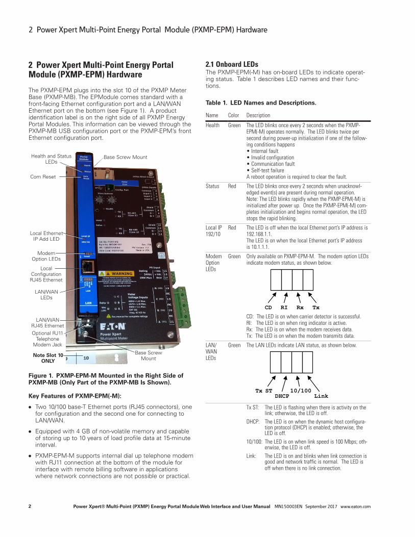
The PXMP-EPM plugs into the slot 10 of the PXMP Meter Base (PXMP-MB). The EPModule comes standard with a front-facing Ethernet configuration port and a LAN/WAN Ethernet port on the bottom (see Figure 1). A product identification label is on the right side of all PXMP Energy Portal Modules. This information can be viewed through the PXMP-MB USB configuration port or the PXMP-EPM’s front Ethernet configuration port.
Figure 1. PXMP-EPM-M Mounted in the Right Side of PXMP-MB (Only Part of the PXMP-MB Is Shown).
Key Features of PXMP-EPM(-M):
●● Two 10/100 base-T Ethernet ports (RJ45 connectors), one for configuration and the second one for connecting to LAN/WAN.
●● Equipped with 4 GB of non-volatile memory and capable of storing up to 10 years of load profile data at 15-minute interval.
●● PXMP-EPM-M supports internal dial up telephone modem with RJ11 connection at the bottom of the module for interface with remote billing software in applications where network connections are not possible or practical.
2.1 Onboard LEDsThe PXMP-EPM(-M) has on-board LEDs to indicate operat-ing status. Table 1 describes LED names and their func-tions.
Table 1. LED Names and Descriptions.
Name Color Description
Health Green The LED blinks once every 2 seconds when the PXMP-EPM(-M) operates normally. The LED blinks twice per second during power-up initialization if one of the follow-ing conditions happens • Internal fault • Invalid configuration • Communication fault • Self-test failure A reboot operation is required to clear the fault.
Status Red The LED blinks once every 2 seconds when unacknowl-edged event(s) are present during normal operation. Note: The LED blinks rapidly when the PXMP-EPM(-M) is initialized after power up. Once the PXMP-EPM(-M) com-pletes initialization and begins normal operation, the LED stops the rapid blinking.
Local IP 192/10
Red The LED is off when the local Ethernet port’s IP address is 192.168.1.1. The LED is on when the local Ethernet port’s IP address is 10.1.1.1.
Modem Option LEDs
Green Only available on PXMP-EPM-M. The modem option LEDs indicate modem status, as shown below.
CD RI Rx Tx CD: The LED is on when carrier detector is successful. RI: The LED is on when ring indicator is active. Rx: The LED is on when the modem receives data. Tx: The LED is on when the modem transmits data.
LAN/WAN LEDs
Green The LAN LEDs indicate LAN status, as shown below.
Tx ST
DHCP10/100
Link
Tx ST: The LED is flashing when there is activity on the link; otherwise, the LED is off.
DHCP: The LED is on when the dynamic host configura-tion protocol (DHCP) is enabled; otherwise, the LED is off.
10/100: The LED is on when link speed is 100 Mbps; oth-erwise, the LED is off.
Link: The LED is on and blinks when link connection is good and network traffic is normal. The LED is off when there is no link connection.
Health and Status LEDs
Local Ethernet IP Add LED
Com Reset
Local Configuration RJ45 Ethernet
Base Screw Mount
Modem Option LEDs
LAN/WAN LEDs
LAN/WAN RJ45 EthernetOptional RJ11
Telephone Modem Jack
Note Slot 10 ONLY
Base Screw Mount

3
3. PXMP-EPM(-M) Installation
Power Xpert® Multi-Point (PXMP) Energy Portal Module Web Interface and User Manual MN150003EN September 2017 www.eaton.com
2.2 COM Reset Switch and Procedure to Reset CommunicationsThe PXMP-EPM(-M) must be configured the first time before it is used. To do so, follow the steps below.
1. Install and secure the PXMP-EPM(-M) into slot 10 of the PXMP Meter Base (PXMP-MB).
2. On power up, press and hold the Com Reset Switch for more than 2 seconds.
3. Within 15 minutes, connect to the PXMP-EPM(-M) module through its local Ethernet port. Refer to Section 4.1 for connection instructions.
4. Login with the default Username and Password. Refer to Section 5.1 for login instructions. The default admin-istrative Username is admin. The default administrative Password is admin.
ote:N For security purposes, please change the adminis-trative Password as soon as possible. In case the administrative Password is lost, the administrative Password can be restored to factory default by fol-lowing the steps listed above.
3. PXMP-EPM(-M) Installation
c WARNINGBE SURE THAT ALL SYSTEM POWER IS OFF WHEN ASSEMBLING A PXMP METER INCLUDING THE INSTALLATION OF THE PXMP-EPM AND ITS ASSOCIATED EXTERNAL COMM. CIRCUITS.
To install a PXMP-EPM(-M) into the PXMP-MB assembly, first remove the metal slot cover on the Meter Base, slot 10 only, using a compatible head screw driver for the screws at top/bottom. Remove the EPM from its packing and remove the black plastic retainers from the mounting screws. Align the EPM connectors and screw mounts with those of the Meter Base. Then push the Module into the Base and tighten the mounting screws until the module housing is tight against the Backplane. The module is secured with captive screws that, when tightened, ground the module to the Meter Base and to the earth ground stud.
ote:N The PXMP-EPM(-M) will not ground to the PXMP-MB if the black plastic retainers are not removed from the mounting screws.
ote:N The PXMP-EPM(-M) will not function properly in a slot other than slot 10.

4
4. PXMP-EPM(-M) Commissioning and Configuration
Power Xpert® Multi-Point (PXMP) Energy Portal Module Web Interface and User Manual MN150003EN September 2017 www.eaton.com
4. PXMP-EPM(-M) Commissioning and Con-figuration
The PXMP-EPM(-M) may be configured either through the front-facing local Ethernet configuration port or through the LAN/WAN Ethernet port on the bottom (see Figure 1).
To set up of the LAN/WAN Ethernet port, User must first connect to the PXMP-EPM(-M) through the local Ethernet configuration port. After the LAN/WAN Ethernet port is configured, the PXMP-EPM(-M) can be accessed and config-ured remotely through the LAN/WAN connection.
4.1 Local Ethernet PortTo configure the PXMP-EPM(-M) module through the local Ethernet configuration port:
1. Connect one end of a standard Ethernet cable to the front facing Ethernet configuration port on the PXMP-EPM(-M), and the other end of the Ethernet cable to a computer.
ote:N The PXMP-EPM(-M) local Ethernet configuration port has a permanent Internet Protocol (IP) address of 192.168.1.1.
2. If Java Runtime Environment (JRE) is not already on the computer, download and install the latest version of JRE from www.java.com.
3. Set the computer’s IP address to 192.168.1.100 by com-pleting the following
a. Click Window’s Start. Then click Settings > Control Panel (Windows 2000) or Control Panel (Windows XP/Vista/7).
b. In Control Panel, click Network and right-click Local PC Area Connection. Select Properties from the shortcut menu.
For Windows 7, in Control Panel, click Network and Internet > Network and Sharing Center > Change adapter settings. Double-click Local Area Connection. Click Properties button.
c. In the Properties dialog, select Internet Protocol (TCP/IP) and click the Properties button.
For Windows 7, in the Local Area Connection Properties dialog window, select Internet Protocol Version 4 (TCP/IPv4) and click the Properties but-ton.
d. In the Internet Protocol (TCP/IP) Properties win-dow, select “Use the following IP address” and then enter the IP address of:
192.168.1.100,
with a Subnet Mask set to:
255.255.255.0
For Windows 7, in the Internet Protocol Version 4 (TCP/IP) Properties window, select “Use the following IP address” and then enter the IP address of:
192.168.1.100,
with a Subnet mask set to:
255.255.255.0
Figure 2. Internet Protocol Version 4 (TCP/IPv4) Properties Dialog Box.
e. Click OK.
4. Launch Internet Explorer and then navigate to:
http://192.168.1.1

5
4. PXMP-EPM(-M) Commissioning and Configuration
Power Xpert® Multi-Point (PXMP) Energy Portal Module Web Interface and User Manual MN150003EN September 2017 www.eaton.com
ote:N
●● When connected to a computer, the Link LED will illu-minate and, when communicating, the 10/100 LED will flicker.
●● When the PXMP-EPM(-M) is connected to a router through its LAN/WAN Ethernet port, and the router has an IP address of:
192.168.1.1,
the PXMP-EPM(-M)’s local Ethernet port automatically switches to an alternative IP address of:
10.1.1.1
The 192/10 LED will illuminate. To reset the local Ethernet port’s IP address back to 192.168.1.1, discon-nect the Ethernet cable to the LAN/WAN Ethernet port, and the press and hold the Com Reset button for at least 3 seconds before releasing.
Once the commissioning is completed, and the connec-tion through the local Ethernet port is no longer needed, disconnect the standard Ethernet cable from the front fac-ing Ethernet configuration port, and change the Internet Protocol (TCP/IP) Properties in Figure 2 back to their original settings.
4.2 LAN/WAN Ethernet PortTo configure the PXMP-EPM(-M) through the LAN/WAN Ethernet port, connect one end of a standard Ethernet cable to the Ethernet port on the bottom of the PXMP-EPM(-M), and the other end of the Ethernet cable to a network.
The PXMP-EPM(-M) ships with Dynamic Host Configuration Protocol (DHCP) enabled. Connect the standard Ethernet cable from the LAN/WAN Ethernet port to a network. Because DHCP is enabled, the User must find the IP address via the local Ethernet port. See Section 5.1 and 5.2 in this manual on how to obtain LAN/WAN Ethernet port’s IP address.
4.3 Configure PXMP Through PXMP-EPM(-M) Using Configuration SoftwareTo support commissioning and configuring the PXMP-MB, Eaton provides a separate PXMP Configuration Software. The software is a Java-based application and is included on a CD provided with each PXMP-MB. The software can also be downloaded from the Eaton Power Xpert Multi-Point Meter Web site at www.eaton.com/meters.
For detailed instructions on configuring PXMP-MB through PXMP-EPM(-M) using the configuration software, please refer to the Power Xpert Multi-Point Meter Configuration Software User Manual (MN150002EN).

6
5. PXMP-EPM(-M) Embedded Web Server Interface
Power Xpert® Multi-Point (PXMP) Energy Portal Module Web Interface and User Manual MN150003EN September 2017 www.eaton.com
5. PXMP-EPM(-M) Embedded Web Server Interface
PXMP-EPM(-M) Embedded Web Server makes data in a PXMP Meter available to Users. Users can access the Web Server from web browsers and connect to the PXMP-EPM(-M) web interfaces over secure network communica-tions.
When users connect to the PXMP-EPM(-M) Embedded Web Server using hypertext transfer protocol (HTTP), the communication proxy automatically redirects the request to an HTTP secure (HTTPS) connection. The HTTPS connec-tion provides bidirectional encryption of communications between the web server and the User. The web server encrypts the session with a digital certificate for authentica-tion.
To install a Root CA Certificate on a client machine, navigate to the ca.html file within the Energy Portal:
https://<PXMP-EPM IP Addr>/ca.html
Click on Root CA Certificate then Open the file and follow the series of screens to install the file.
Store the file within “Trusted Root Certification Authorities” to access the Energy Portal without warning messages.
Figure 3. Root CA Installation Screen.
5.1 Login Into PXMP-EPM(-M) Web ServerOnce users connect to the PXMP-EPM(-M) Embedded Web Server, either through Local Ethernet Configuration Port or LAN, a Power Xpert Multi Point Meter Login screen is dis-played (see Figure 4).
Figure 4. Power Xpert Multi-Point Meter Login Screen.
The PXMP-EPM(-M) web server supports individual Usernames and Passwords to ensure that User access is limited to authorized information only. A User signs into the web server by providing Username and corresponding Password.
The Energy Portal Login screen appears if the User has not previously signed in. The User provides login credentials by entering appropriate Username and Password. The login credentials are then validated by the web server after the User clicks the “Login” button.
ote:N The default administrative Username is admin. The default administrative Password is unique to each Energy Portal and the password is provided on the device label. For security purposes, please change the Password as soon as possible after login.

7
5. PXMP-EPM(-M) Embedded Web Server Interface
Power Xpert® Multi-Point (PXMP) Energy Portal Module Web Interface and User Manual MN150003EN September 2017 www.eaton.com
5.2 User Access LevelsThe web server offers 2 levels of User access:
●● Facility Manager and
●● Tenant(s).
The Facility Manager has administrative rights, and can add, modify, or remove Tenant accounts, as well as change account Passwords. The Tenant(s) can customize dash boards, view their own load profiles, and print results.
Depending on the User-supplied login credentials, the web server provides separate web interfaces after successful logins for Facility Manager and Tenant(s). The web interfac-es are designed to help the Facility Manager and Tenant(s) complete energy-monitoring-related tasks. Table 2 lists tasks the Facility Manager and Tenant(s) can perform via menu options in web interfaces.
Table 2. Menu Options for the Facility Manager and Tenant(s).
Menu Options Facility Manager Tenant(s)
Dashboard
Meter
Power
Load Profile
Channel Data
Events
Setup
5.2.1 Login as Facility ManagerFor the Facility Manager, a typical web interface screen is similar to the one shown in Figure 5. Click on the Welcome, Administrator! link in the upper black bar to sign off the web server.
Figure 5. Overview Screen for the Facility Manager.
8
5. PXMP-EPM(-M) Embedded Web Server Interface
Power Xpert® Multi-Point (PXMP) Energy Portal Module Web Interface and User Manual MN150003EN September 2017 www.eaton.com
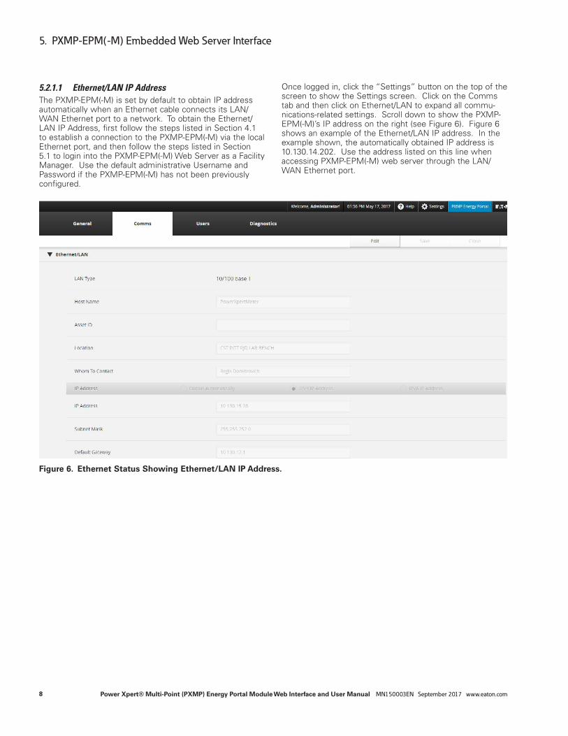
5.2.1.1 Ethernet/LAN IP AddressThe PXMP-EPM(-M) is set by default to obtain IP address automatically when an Ethernet cable connects its LAN/WAN Ethernet port to a network. To obtain the Ethernet/LAN IP Address, first follow the steps listed in Section 4.1 to establish a connection to the PXMP-EPM(-M) via the local Ethernet port, and then follow the steps listed in Section 5.1 to login into the PXMP-EPM(-M) Web Server as a Facility Manager. Use the default administrative Username and Password if the PXMP-EPM(-M) has not been previously configured.
Once logged in, click the “Settings” button on the top of the screen to show the Settings screen. Click on the Comms tab and then click on Ethernet/LAN to expand all commu-nications-related settings. Scroll down to show the PXMP-EPM(-M)’s IP address on the right (see Figure 6). Figure 6 shows an example of the Ethernet/LAN IP address. In the example shown, the automatically obtained IP address is 10.130.14.202. Use the address listed on this line when accessing PXMP-EPM(-M) web server through the LAN/WAN Ethernet port.
Figure 6. Ethernet Status Showing Ethernet/LAN IP Address.
9
5. PXMP-EPM(-M) Embedded Web Server Interface
Power Xpert® Multi-Point (PXMP) Energy Portal Module Web Interface and User Manual MN150003EN September 2017 www.eaton.com
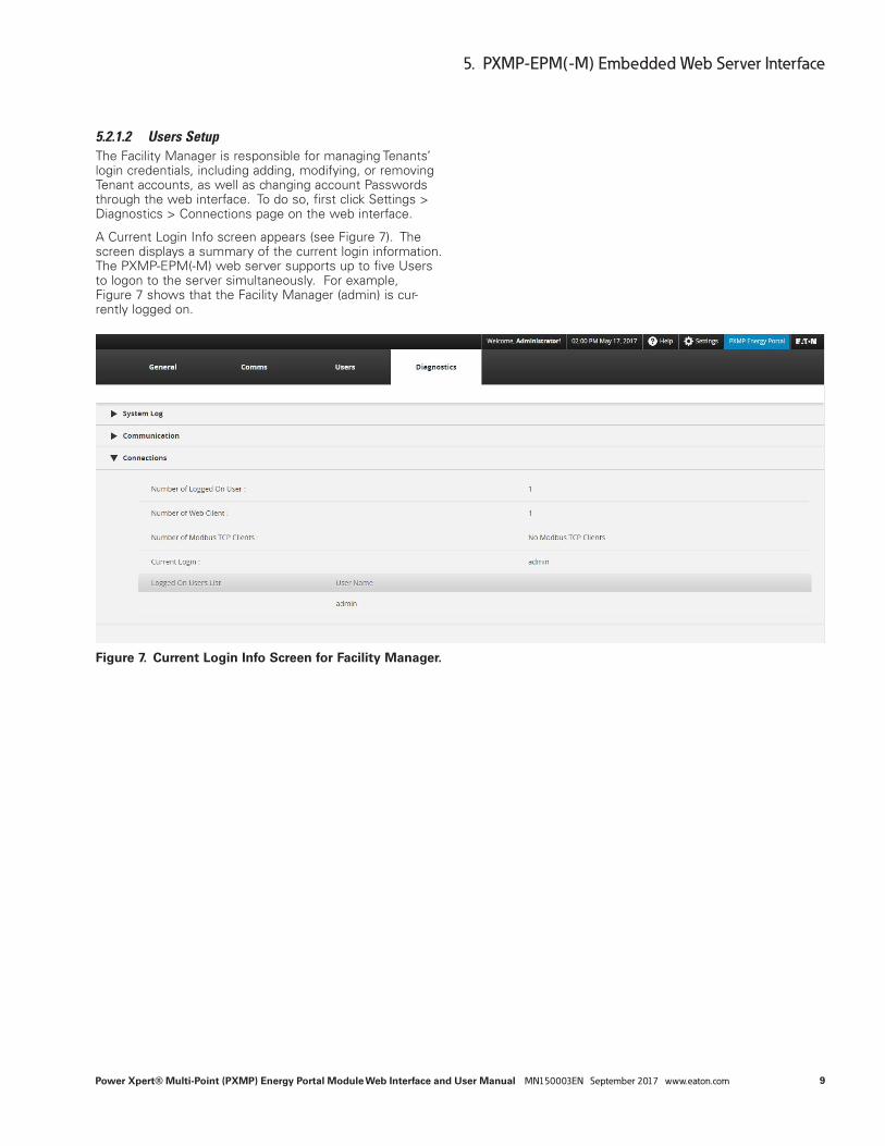
5.2.1.2 Users SetupThe Facility Manager is responsible for managing Tenants’ login credentials, including adding, modifying, or removing Tenant accounts, as well as changing account Passwords through the web interface. To do so, first click Settings > Diagnostics > Connections page on the web interface.
A Current Login Info screen appears (see Figure 7). The screen displays a summary of the current login information. The PXMP-EPM(-M) web server supports up to five Users to logon to the server simultaneously. For example, Figure 7 shows that the Facility Manager (admin) is cur-rently logged on.
Figure 7. Current Login Info Screen for Facility Manager.

10
5. PXMP-EPM(-M) Embedded Web Server Interface
Power Xpert® Multi-Point (PXMP) Energy Portal Module Web Interface and User Manual MN150003EN September 2017 www.eaton.com
5.2.1.2.1 Add New Tenant AccountTo set up Users, click Settings > Users > Users, and a Users Setup screen appears (see Figure 8). The screen displays a list of existing Users. The Facility Manager can manage Tenants’ login credentials by adding new Tenant accounts, editing or removing existing Tenant accounts, as well as changing account Passwords.
Figure 8. Users Setup Screen for Facility Manager.
To add a new Tenant account, click the “Add User” but-ton. Enter the appropriate User Name, Tenant Name, and Password in the provided text boxes (see Figure 9). The User Name and Password are used by the Tenant to login to the Energy Portal Login screen. The Tenant Name is used as an identification tag.
ote:N A secure password with a minimum of 8 and maxi-mum of 32 characters is recommended. A secure password contains at least:
●● One digit from 0-9;
●● One lowercase character;
●● One uppercase character; and
●● One special symbol, such as @, #, $, %, _.

11
5. PXMP-EPM(-M) Embedded Web Server Interface
Power Xpert® Multi-Point (PXMP) Energy Portal Module Web Interface and User Manual MN150003EN September 2017 www.eaton.com
Figure 9. Add New Tenant Account.
Click “+” button to complete adding the new Tenant account. The Users Setup screen is then updated with the newly added Tenant account.
5.2.1.2.2 Associate Meters with Tenant AccountsEach Tenant is allowed to have one or more meters associ-ated with the Tenant account. Once a meter is assigned to a Tenant, it is no longer available to other Tenants. To add or modify associated meters for each account, click the “Add Meter” button on the corresponding account. An “Add Meter for Tenant” dialog box appears (see Figure 10).
Figure 10. Add Meter for Tenant.

12
5. PXMP-EPM(-M) Embedded Web Server Interface
Power Xpert® Multi-Point (PXMP) Energy Portal Module Web Interface and User Manual MN150003EN September 2017 www.eaton.com
Click the “Add More Meter” button in the dialog box, a drop-down box with a list of energy or pulse meters appears (see Figure 11).
Figure 11. List of Available Energy or Pulse Meters.
The Facility Manager can select multiple meters by pressing and holding down the CTRL key on the keyboard while click-ing desired meters from the list. In the example shown in Figure 11, two meters have been selected. Click the “Save” button to add selected meters to the Tenant account.

13
5. PXMP-EPM(-M) Embedded Web Server Interface
Power Xpert® Multi-Point (PXMP) Energy Portal Module Web Interface and User Manual MN150003EN September 2017 www.eaton.com
When the Facility Manager is done with adding meters to the Tenant account, click the “Save” button, shown in Figure 12, to complete the task. Otherwise, choose another meter under the drop down box to add or “Delete Meter” button to modify the added meter list.
Figure 12. Meters Added to Tenant Account.
5.2.1.2.3 Remove Tenant AccountTo remove a Tenant account, the account must be first dis-sociated with any meters. To do so, click the “Add Meter” button for the corresponding Tenant account and, in the “Add Meter for Tenant” dialog box, select all meters from the Meter List and click the “Delete Meter” button (see Figure 12).
Once all associated meters have been removed from cur-rent Tenant account, click the “Save” button to return to the User Setup screen. In the User Setup screen, click the “x” button to delete current Tenant account.
ote:N The “Delete Meter” button dissociates selected meters from the current Tenant account. It does not disable or remove meters physically from the PXMP meter installation. If needed, the Facility Manager can always associate those deleted meters back to the same Tenant or to another Tenant account by clicking the “Add More Meter” button for appropriate Tenant account shown in Figure 12

14
5. PXMP-EPM(-M) Embedded Web Server Interface
Power Xpert® Multi-Point (PXMP) Energy Portal Module Web Interface and User Manual MN150003EN September 2017 www.eaton.com
5.2.2 Login as Tenant(s)When a User enters the appropriate Username and Password provided by the Facility Manager and logs in as a Tenant, the following menu options are available:
●● Overview
●● Energy
For example, in Figure 10, the Facility Manager has set up login credentials for three different tenants. When tenant 3 logs into the PXMP-EPM(-M) web server, the web interface appears as shown in Figure 13.
Figure 13. Overview Screen for Tenant(s).

15
5. PXMP-EPM(-M) Embedded Web Server Interface
Power Xpert® Multi-Point (PXMP) Energy Portal Module Web Interface and User Manual MN150003EN September 2017 www.eaton.com
5.3 OverviewThe Overview page displays an overview of the most perti-nent current meter readings. From this page, you can navi-gate to the Trends, Energy, Channels, Timeline, and Settings pages. The navigational buttons are in a row at the top of the screen.
Figure 14. Overview Screen – Add Modules.
5.3.1 Common Controls for Selecting Information Under the Trends tab, the Meter and Power pages share many features. These pages provide drop-down menus and radio buttons to select the information to be viewed and options for viewing it. For example, in the Meter page the left-side drop-down menu selects how voltage is viewed: Line-Line or Line-Neutral. The radio buttons select the volt-age information to view: AB, BC, or CA.
In order to zoom into details on a graph, use the zoom fea-ture by clicking and dragging in the plot area to manually zoom or use the drop-down menu, which provides multiple options for time ranges.
A table containing all of the plotted data points is beneath the graph. You can scroll through this to view individual data points.
Most pages have an Export Data/Download button. The Export Data function will save the set of data to either a comma-separated values (CSV) file or will display the infor-mation in your default .csv file viewer (such as Microsoft Excel). Each zoom level provides a different time interval of data.
Navigational Buttons to Various Pages Time and Date Link to Manual Events Indicator

16
5. PXMP-EPM(-M) Embedded Web Server Interface
Power Xpert® Multi-Point (PXMP) Energy Portal Module Web Interface and User Manual MN150003EN September 2017 www.eaton.com
Figure 15. Page Controls.
Data Selection Controls Pan Controls Zoom Drop Down
Export Data Button
Data Points In Displayed Set of Data

17
5. PXMP-EPM(-M) Embedded Web Server Interface
Power Xpert® Multi-Point (PXMP) Energy Portal Module Web Interface and User Manual MN150003EN September 2017 www.eaton.com
5.3.2 MapThe map feature provides the Facility Manager with a great view of the facility and the quick summary of the energy consumption in different parts of the facility. To upload a new map, click the highlighted icon in the left corner of the Map section and select your new image.
Figure 16. Overview Screen for Tenant(s).
Once an image file is selected and uploaded to the Map section as its background, the Facility Manager can then mark the energy or pulse meters’ locations on the map. To do so, click on the icon that looks like a pin, in the left cor-ner of the Map section. Your mouse will have a hand icon and you can choose where you want to add a new meter. Once you click where you want to place a meter, you will get a dialog box as shown in the Figure 17.
Figure 17. Add Meter.

18
5. PXMP-EPM(-M) Embedded Web Server Interface
Power Xpert® Multi-Point (PXMP) Energy Portal Module Web Interface and User Manual MN150003EN September 2017 www.eaton.com
The Facility Manager can select desired meters by clicking on the “Meter No.” dropdown list. Click the “Apply” button to add the selected meter to the map module. The meter’s location is marked by a symbol on the map (see Figure 18).
Figure 18. Meter Location on Map.

19
5. PXMP-EPM(-M) Embedded Web Server Interface
Power Xpert® Multi-Point (PXMP) Energy Portal Module Web Interface and User Manual MN150003EN September 2017 www.eaton.com
The Facility manager can view meter information associated with a location by clicking appropriate symbols on the map (see Figure19). The following information is displayed for an energy meter:
●● Meter Name;
●● Total kWh (Forward);
●● Peak W (Forward); and
●● Peak W Today (Forward).
If the meter is a pulse meter, then the following information is displayed:
●● Meter Name;
●● Tenant Name;
●● Pulse Count;
●● Scaled Value; and
●● Unit.
Figure 19. Meter Details.
To delete a location from the map, click on the location sym-bol, then select “Delete” from the pop-up menu to remove the location from the map (see Figure 19). To change a meter’s location on the map, first delete the location from the map, then click the icon to add the meter to the desired spot.

20
5. PXMP-EPM(-M) Embedded Web Server Interface
Power Xpert® Multi-Point (PXMP) Energy Portal Module Web Interface and User Manual MN150003EN September 2017 www.eaton.com
5.3.3 Overview for TenantWhen logged in as a Tenant, the User can choose from the Overview screen and Energy screen. The Overview screen displays the following information:
●● Load Profile;
●● Meter Summary; and
●● Real Time Values.
Figure 20 shows the Overview screen for Tenant 3. Note that the Tenant can select any meter associated with the Tenant’s account from the Meter List for display.
Figure 20. Overview Screen for Tenant(s).
In the load profile section, the Tenant can also select to display a real, reactive, or apparent power quantity, such as Forward W, Q2 Var, or Q1Q4 kVAh, by choosing appropriate item from the Parameter drop-down list. In addition, the load profile module also allows the Tenant to make the fol-lowing comparisons:
●● Today with Yesterday;
●● This Week with Last Week; and
●● This Month with Last Month.
The default value for comparison is “Today with Yesterday.”
Time and date

21
5. PXMP-EPM(-M) Embedded Web Server Interface
Power Xpert® Multi-Point (PXMP) Energy Portal Module Web Interface and User Manual MN150003EN September 2017 www.eaton.com
5.4 Trends ScreenThe Trends screen is visible to Facility Manager only. The Facility Manager can select from either line-neutral or line-line voltages, currents, or temperature data for display. The PXMP-EPM(-M) calculates and stores those trend data every five minutes, and displays relevant trend data in the Meter screen as well as in the Power screen.
5.4.1. Meter PageIn the Meter page (see Figure 21), based on the User’s selection in the left side, the corresponding interval average and min/max values are displayed in graphical formats on the right side. The Facility Manager can also use the zoom drop down to examine data trends over time. The bottom of the display shows the tabular view of the interval data.
Figure 21. Meter Page.
As described in Section 5.3.1, in order to zoom into details on a graph, use the zoom feature by click ing and dragging in the plot area to manually zoom or use the drop-down menu, which provides multiple options for time ranges.
To save the displayed graph data, click the Export Data icon. This will save the set of data to either a comma-separated values (CSV) file or will display the informa tion in your default .csv file viewer (such as Microsoft Excel). Each zoom level provides a different time interval of data.
• (Zoom1) 48-hour range of 5-minute data
• (Zoom2) 8-day range of 15-minute data
• (Zoom3) 28-day range of 1-hour data
• (Zoom4) 392-day (56-week) range of 8-hour data
• (Zoom5) 1,449-day (207-week) range of 1-week data

22
5. PXMP-EPM(-M) Embedded Web Server Interface
Power Xpert® Multi-Point (PXMP) Energy Portal Module Web Interface and User Manual MN150003EN September 2017 www.eaton.com
The Facility Manager can reset min/max values, trend data, and profile data through the Energy Portal web interface. When the Facility Manager clicks the “Choose an Action...” drop down, they can select the appropriate entry to reset metered data in the PXMP-EPM(-M).
ote:N Reset operations only clear displayed data. They do not clear or change any archived FTP data.
Figure 22. Choose an Action.
5.4.1.1 Reset All Min/MaxIn the Choose an Action... drop down, selecting “Reset All Min/Max” will clear all min/max values, as well as the associated time stamps stored in the PXMP-EPM(-M). The “Reset All Min/Max” will at the same time clear min/max values and the associated time stamps in the Power screen (see Section 5.4.2, Figure 23.
5.4.1.2 Reset Trend DataIn the Choose an Action... drop down, selecting “Reset Trend Data” will clear the graph and the table in Figure 26. The “Reset All Min/Max” will, at the same time, clear the graph and the table in the Power screen (Section 5.4.2, Figure 23).
5.4.1.3 Reset Profile DataIn the Choose an Action... drop down, selecting “Reset Profile Data” will clear profile data shown in the graph and the table shown in Figure 25. The “Reset Profile Data” will at the same time clear the graph in the load profile module in the Facility Manager’s dashboard (see Section 5.3.1).
5.4.2 Power PageThe Power page is visible to Facility Manager only. By selecting a meter from the Meter drop-down list on the left side of the screen, the Facility Manager can obtain cor-responding average and min/max values of power and fre-quency data.
The power and frequency data are displayed in both graphical and tabular formats on the right side of the Power screen. Table 4 gives available power and frequency data that can be displayed.

23
5. PXMP-EPM(-M) Embedded Web Server Interface
Power Xpert® Multi-Point (PXMP) Energy Portal Module Web Interface and User Manual MN150003EN September 2017 www.eaton.com
Table 4. Available Power and Frequency Data.
Meter • Main Meter1
• All Tenant Meter(s)
Power • System Power1, 2
• Real Power (Watts)
• Reactive Power (var)
• Apparent Power (VA)
• Power Factor
Frequency • Frequency (Hz)1 Default display. 2 Only available when the main meter is selected.
Figure 23 shows an example of the Power page. Similar to the Meter page, the Facility Manager can use the zoom feature by clicking and dragging in the plot area to manually zoom or use the drop-down menu, which provides multiple options for time ranges.
To save the displayed graph data, click the Export Data icon. This will save the set of data to either a comma-separated values (CSV) file or will display the informain your default .csv file viewer (such as Microsoft Excel). Each zoom level provides a different time interval of data.
Figure 23. Power Screen for Facility Manager.
In the example shown in Figure 23, E00_AccMeter is a system meter. If the system meter is selected, then in addition to the System Power option, the data contained in Table 5 may also be selected and displayed from the Power drop-down list.
Table 5. Available System Meter Power Data.
Real Power (Watts) Per-Phase Real Power
• A (Watts) • B (Watts) • C (Watts)
Reactive Power (var) Per-Phase Reactive Power
• A (vars) • B (vars) • C (vars)
Apparent Power (VA) Per-Phase Apparent Power
• A (VA) • B (VA) • C (VA)
Power Factor Per-Phase Power Factor
• A • B • C
ote:N The “System Power” option in the “Power” drop-down list is only available for the main meter. It is not available when a meter other than the system meter is selected.
ote:N The prefix “Exx” is added to the meter names to indicate the energy meters.

24
5. PXMP-EPM(-M) Embedded Web Server Interface
Power Xpert® Multi-Point (PXMP) Energy Portal Module Web Interface and User Manual MN150003EN September 2017 www.eaton.com
5.5 Energy ScreenThe Energy screen is visible to both the Facility Manager and Tenant(s). The Facility Manager has access to all meters, and can reset individual meter’s energy or demand data. The Tenant(s) have access only to the meters associ-ated with the Tenant’s account, and cannot reset energy or demand data.
5.5.1 Energy for Facility ManagerFigure 24 shows an example of a Energy screen for Facility Manager. Based on the selected parameter list, Tenant ID and meter list on the left, corresponding data are displayed on the right side of the Energy screen. In the example shown in Figure 24 the main meter E00_AccMeter’s energy and demand information are displayed.
Figure 24. Energy Screen for Facility Manager.
25
5. PXMP-EPM(-M) Embedded Web Server Interface
Power Xpert® Multi-Point (PXMP) Energy Portal Module Web Interface and User Manual MN150003EN September 2017 www.eaton.com
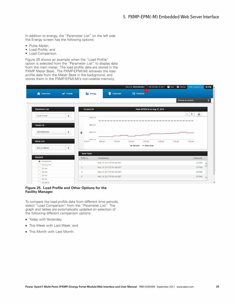
In addition to energy, the “Parameter List” on the left side the Energy screen has the following options:
• Pulse Meter; • Load Profile; and • Load Comparison.
Figure 25 shows an example when the “Load Profile” option is selected from the “Parameter List” to display data from the main meter. The load profile data are stored in the PXMP Meter Base. The PXMP-EPM(-M) retrieves the load profile data from the Meter Base in the background, and stores them in the PXMP-EPM(-M)’s non-volatile memory.
Figure 25. Load Profile and Other Options for the Facility Manager.
To compare the load profile data from different time periods, select “Load Comparison” from the “Parameter List.” The graph and tables are automatically updated on selection of the following different comparison options:
●● Today with Yesterday;
●● This Week with Last Week; and
●● This Month with Last Month.

26
5. PXMP-EPM(-M) Embedded Web Server Interface
Power Xpert® Multi-Point (PXMP) Energy Portal Module Web Interface and User Manual MN150003EN September 2017 www.eaton.com
Figure 26 shows an example of load comparison for E00_AccMeter. The comparison is made on Q1 var data between today and yesterday.
Figure 26. Load Comparison.
The “Tenant ID” drop-down list on the left side of the load profile screen allows the Facility Manger to select meters associated with a specific Tenant (see Figure 27).

27
5. PXMP-EPM(-M) Embedded Web Server Interface
Power Xpert® Multi-Point (PXMP) Energy Portal Module Web Interface and User Manual MN150003EN September 2017 www.eaton.com
Figure 27. Select Tenant in Energy Screen for Facility Manager.
For example, in Figure 27, the Tenant with an ID of RO user is selected. The “Meter List” is then automatically updated to include only meters associated with this specific tenant (see Figure 28).
Figure 28. Select Tenant Meter in Energy Screen for Facility Manager.

28
5. PXMP-EPM(-M) Embedded Web Server Interface
Power Xpert® Multi-Point (PXMP) Energy Portal Module Web Interface and User Manual MN150003EN September 2017 www.eaton.com
5.5.2 Energy for TenantThe Energy screen for Tenant(s) (see Figure 29) is similar to the Energy screen for the Facility Manager. However, the tenant does not have the following features:
●● Selection of a Tenant from the “Tenant ID” drop-down list;
●● Access to the main meter and other Tenants’ meters; and
●● “Reset Energy” and “Reset Demand” buttons.
Figure 29. Energy Screen for Tenant(s).

29
5. PXMP-EPM(-M) Embedded Web Server Interface
Power Xpert® Multi-Point (PXMP) Energy Portal Module Web Interface and User Manual MN150003EN September 2017 www.eaton.com
5.6 Channel ScreenThe Channel screen is visible to the Facility Manager only. It displays data in a tabular format from all meter modules (excluding pulse input and digital output modules) installed on the PXMP-MB Meter Base. Figure 30 shows the chan-nel screen of a PXMP-EPM(-M).
The information shown in Figure 30 provides a snapshot of all meter modules. For example, it shows that a total of four cards have been installed in slots 1 through 4 on the PXMP-MB Meter Base. Each card has six channels. Only channels four through six on each card have non-zero cur-rents measured.
Figure 30. Channel Screen for Facility Manager.

30
5. PXMP-EPM(-M) Embedded Web Server Interface
Power Xpert® Multi-Point (PXMP) Energy Portal Module Web Interface and User Manual MN150003EN September 2017 www.eaton.com
5.7 Timeline ScreenThe Timeline screen is visible to Facility Manager only. The Timeline screen displays events associated with the PXMP Meter. An event log stores event information in the PXMP Meter Base. The PXMP-EPM(-M) retrieves event information from the Meter Base, and stores it in the PXMP-EPM(-M)’s non-volatile memory. A maximum of 20 events are stored and displayed on the left side of the Events screen (see Figure 31).
Figure 31. Timeline Screen for Facility Manager.
Once an event on the left side of the events screen is selected, the corresponding event details are displayed on the right side of the events screen with the following:
●● Event ID;
●● Event Details;
●● Start Time;
●● Clear Time;
●● Cause; and
●● Value.
If there is an alarm associated with the selected event, then alarm details are also displayed along with the event details. Alarm details consist of the following:
●● Alarm ID;
●● Alarm Type; and
●● Minimum Duration.

31
5. PXMP-EPM(-M) Embedded Web Server Interface
Power Xpert® Multi-Point (PXMP) Energy Portal Module Web Interface and User Manual MN150003EN September 2017 www.eaton.com
After new event(s) are captured, the Facility Manager can acknowledge the event(s). If the event(s) have not been acknowledged, then the “Timeline screen” button is displayed with a red event indicator (see Figure 32). To acknowledge all unacknowledged event(s), click the “Acknowledge All” button on the upper left side of the Timeline screen. A dialog box appears to confirm this oper-ation with the Facility Manager (see Figure 32).
Figure 32. Confirmation to Acknowledge Events for Facility Manager.
Once existing events have been acknowledged, the “Timeline” menu button is no longer displayed with a red background. The button will display a red event indicator again when any new unacknowledged event(s) is captured.
5.8 Settings ScreenThe Settings screen and all its settings are visible to the Facility Manager only. It allows the Facility Manager to per-form following tasks:
●● Users Setup;
●● Clock Setup;
●● Communications Setup;
●● Modem Setup;
●● System Information; and/or
●● Diagnostics Information.
For Users Setup, please refer to Section 5.2.1.2 of this manual. Follow the steps in that section to complete other tasks in the above list.
5.8.1 General Screen
5.8.1.1 Clock (NTP)Click the “Clock” drop down by going to General > Clock to display the current system time, time zone, and time sync source(s) if available (see Figure 33). To update the current system time, such as the year and date, time zone, and time synchronization servers that support network time pro-tocol (NTP), click the “Edit” button on the top right of Clock Information screen.

32
5. PXMP-EPM(-M) Embedded Web Server Interface
Power Xpert® Multi-Point (PXMP) Energy Portal Module Web Interface and User Manual MN150003EN September 2017 www.eaton.com
Figure 33. Clock Information Screen.
An example of the Clock Setup Edit screen is shown in Figure 34. The Facility Manager can set up appropriate time and time zone by using the drop-down listed provided. To setup NTP time synchronization server(s), first select the “Synchronize with NTP server(s)” option, and then enter
NTP Server IP address(es) or hostname(s). Select “No time Synchronization” option if the PXMP-EPM(-M) time does not need to be synchronized with NTP servers. When done, click the “Save” button on the top right of the screen to return to the Clock Information screen.
Figure 34. Clock Setup Screen.

33
5. PXMP-EPM(-M) Embedded Web Server Interface
Power Xpert® Multi-Point (PXMP) Energy Portal Module Web Interface and User Manual MN150003EN September 2017 www.eaton.com
5.8.1.2 System InformationA Facility Manager can view system information, includ-ing clock, hardware and firmware information of the PXMP meter base and module by clicking on the General screen.
5.8.1.3 HardwareClick on General > System > Hardware to display the cur-rent system hardware information (see Figure 35).
The system hardware page provides information for:
●● Energy Portal;
●● Meter Base; and
●● Module in Each Slot.
The system hardware information may be used for trouble-shooting purpose.
Figure 35. System Hardware Screen.

34
5. PXMP-EPM(-M) Embedded Web Server Interface
Power Xpert® Multi-Point (PXMP) Energy Portal Module Web Interface and User Manual MN150003EN September 2017 www.eaton.com
5.8.1.4 FirmwareThe Firmware screen displays component names, assembly names, part numbers, and their respective versions for the PXMP-MB and modules in slots 1-10 (see Figure 36). Note that the assembly name is also the PXMP component’s catalog number.
Figure 36. System Firmware Screen.
To upgrade firmware for the PXMP-EPM(-M) module or PXMP meter base, selecting an option in the “Select a device” (see Figure 36). The “Energy Portal” option refers to the firmware upgrade for the PXMP-EPM(-M) module, while the “Meter Base” option refers to the firmware upgrade for the PXMP meter base.

35
5. PXMP-EPM(-M) Embedded Web Server Interface
Power Xpert® Multi-Point (PXMP) Energy Portal Module Web Interface and User Manual MN150003EN September 2017 www.eaton.com
Once a device is selected, click the “Upgrade” button. The web server prompts with a screen similar to that shown in Figure 37. Click the “Choose Upgrade File” button and select the zip archive that contains the desired firmware upgrade. Click the “Start Upgrade” button in the Upgrade Firmware page to initiate firmware upgrade.
Figure 37. Upgrade Firmware Page.

36
5. PXMP-EPM(-M) Embedded Web Server Interface
Power Xpert® Multi-Point (PXMP) Energy Portal Module Web Interface and User Manual MN150003EN September 2017 www.eaton.com
To reboot the PXMP-EPM(-M) module or the PXMP meter base, select desired device in “Select a device” in Figure 38. Select the “Energy Portal” option to reboot the PXMP-EPM(-M) module, and select the “Meter Base” option to reboot PXMP meter base. Click the “Reboot” button to execute a reboot.
Figure 38. Reboot a Device from System Firmware Page.
To view PXMP-EPM(-M) firmware licenses, click the “License” button (see Figure 38). Upon clicking licenses, a pop-up will now appear asking for credentials for validating the user. Click the folder name to view individual license.

37
5. PXMP-EPM(-M) Embedded Web Server Interface
Power Xpert® Multi-Point (PXMP) Energy Portal Module Web Interface and User Manual MN150003EN September 2017 www.eaton.com
Figure 39. View Firmware Licenses Page.
38
5. PXMP-EPM(-M) Embedded Web Server Interface
Power Xpert® Multi-Point (PXMP) Energy Portal Module Web Interface and User Manual MN150003EN September 2017 www.eaton.com
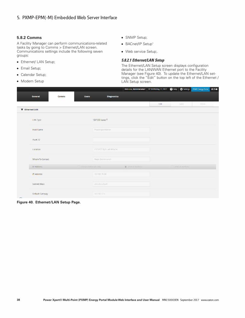
5.8.2 CommsA Facility Manager can perform communications-related tasks by going to Comms > Ethernet/LAN screen. Communications settings include the following seven groups:
●● Ethernet/ LAN Setup;
●● Email Setup;
●● Calendar Setup;
●● Modem Setup
●● SNMP Setup;
●● BACnet/IP Setup1
●● Web service Setup;.
5.8.2.1 Ethernet/LAN SetupThe Ethernet/LAN Setup screen displays configuration details for the LAN/WAN Ethernet port to the Facility Manager (see Figure 40). To update the Ethernet/LAN set-tings, click the “Edit” button on the top left of the Ethernet / LAN Setup screen.
Figure 40. Ethernet/LAN Setup Page.

39
5. PXMP-EPM(-M) Embedded Web Server Interface
Power Xpert® Multi-Point (PXMP) Energy Portal Module Web Interface and User Manual MN150003EN September 2017 www.eaton.com
An example of the Ethernet/LAN Setup Edit page is shown in Figure 41. The Facility Manager can fill in appropriate information for host name, asset ID, location, and who to contact.
The PXMP-EPM(-M) offers three different ways to configure IP address when it is connected to a network through the LAN/WAN Ethernet port. The IP address may be obtained automatically by selecting the “Obtain Automatically” option. Conversely, depending on the communications protocol used, the Facility Manager may manually setup the IP address by selecting either “IPv4 IP Address” or “IPv6 IP Address,” and entering appropriate information for IP address, subnet mask/prefix length, default gateway, pre-ferred DNS server, alternate DNS server, and domain name.
To enable access to PXMP-EPM(-M) via the secure file transfer protocol (SFTP), enter the appropriate Password in the “SFTP Password” box. The Facility Manager can further enable Modbus/TCP or SFTP file compression fea-tures by checking appropriate checkbox next to the “Enable Modbus/TCP” or “SFTP File Compression” option. Uncheck the checkbox to disable the feature. When done, click the “Save” button on the top right of the page to return to the Ethernet/LAN Setup screen.
ote:N The default SFTP Password is “ftp” (without quota-tion marks) if the SFTP Password field in Figure 41 is left blank. See Section 6.1 for details on how to access to PXMP-EPM(-M) SFTP service.
Figure 41. Ethernet/LAN Setup Edit Page.

40
5. PXMP-EPM(-M) Embedded Web Server Interface
Power Xpert® Multi-Point (PXMP) Energy Portal Module Web Interface and User Manual MN150003EN September 2017 www.eaton.com
5.8.2.2 Email SetupThe Email Setup screen displays email configuration details to a Facility Manager (see Figure 42). To update the email settings, click the “Edit” button on the top right of the Email Setup screen.
Figure 42. Email Setup Screen.
Figure 43 shows an example of the Email Setup Edit page. The Email Setup Edit page is divided into three sections. In the first section, the Facility Manager provides information to set up an account to send emails. This includes account, Password, simple mail transfer protocol (SMTP) server, and SMTP port. The SMTP port is selected from a list of avail-able choices, including ports 25, 465, and 587. Note that the information shown in Figure 43 is for illustration purpose only.
In the second section, the Facility Manager can designate up to five email addresses. Depending on the Facility Manager’s selections, the PXMP-EPM(-M) web server sends email updates to the designated email addresses either periodically, when an alarm occurs, or when either criteria is met.

41
5. PXMP-EPM(-M) Embedded Web Server Interface
Power Xpert® Multi-Point (PXMP) Energy Portal Module Web Interface and User Manual MN150003EN September 2017 www.eaton.com
Figure 43. Email Setup Edit Page.
In the third section, the Facility Manager may decide which of the following items are included in the periodic email:
●● Energy Data;
●● Events Data; and/or
●● Load Profile Data.
A zip file may be attached in the email sent by the Facility Manager. The zip file includes load profile data logged dur-ing the month. The Facility Manager may choose an appro-priate file name for the zip file, and encrypts the attached zip file by specifying a Password.
The PXMP-EPM(-M) web server can be set up to send alarm emails or periodic emails to designated email addresses. Alarm emails are generated and sent as soon as alarms are triggered. Figure 44 shows a sample alarm email. Periodic emails are generated and sent according to the schedule set in the Calendar (Section 5.9.2.3). Figure 45 shows a sample periodic email.

42
5. PXMP-EPM(-M) Embedded Web Server Interface
Power Xpert® Multi-Point (PXMP) Energy Portal Module Web Interface and User Manual MN150003EN September 2017 www.eaton.com
Figure 44. Alarm E-Mail.
The alarm e-mail contains Event ID, Event Start and Clear Timestamps, Description, Cause, and other alarm-related information. For example, in Figure 44, an overvoltage event is shown in the sample alarm email. The overvoltage event started on Saturday, February 22, 2014 at 00:00:16, and cleared at 00:01:07 on the same day.
In Figure 44, the Description field shows the voltage limit associated with the event. The Cause field displays a numerical value to indicate the actual cause of the alarm. The value 11 represents an overvoltage event. A complete list of numerical values and corresponding causes is given in Table B.5.
If the event has not been acknowledged by the Facility Manager, then the “Is Acked” field displays “No.” Please refer to Section 5.8 of this manual for instructions on how to acknowledge an event.
For periodic e-mails, the message body and attachment provide energy, events, and load profile data. In Figure 45, the e-mail message body is divided into the following two sections
●● Event Time
●● Event Details
The Event Time lists the time when the periodic e-mail is generated. The Event Details lists energy and demand data under the “Aggregate Meter” and “Virtual Meters” sections.

43
5. PXMP-EPM(-M) Embedded Web Server Interface
Power Xpert® Multi-Point (PXMP) Energy Portal Module Web Interface and User Manual MN150003EN September 2017 www.eaton.com
Figure 45. Periodic E-Mail.
In Figure 45, the PXMP-EPM(-M)’s total forward and reverse energy is listed under the “Aggregate Meter” section. The peak forward (Fwd) and reverse (Rev) demands and their corresponding time are listed in the same section.
For individual meters, their energy data is listed under the “Virtual Meters” section. For example, in Figure 45, Meter 2 has a forward energy of 2030.5 kWh, and a peak forward demand of 12787.5293 W. The peak demand occurred on Wednesday, Feb. 19, 2014 at 14:44 local time. The data also indicates that Meter 2 is set up to operate in UTC-05:00 Time Zone, i.e., U.S. Eastern Time Zone.
The attached zip file contains load profile data logged dur-ing the current calendar month. Figure 46 shows contents of a sample e-mail attachment. The zip file also contains load profile data logged during the previous calendar month. Please refer to Section 6.2.1 for detailed explanations of contents and formats of the load profile data files.

44
5. PXMP-EPM(-M) Embedded Web Server Interface
Power Xpert® Multi-Point (PXMP) Energy Portal Module Web Interface and User Manual MN150003EN September 2017 www.eaton.com
Figure 46. Load Profile Data Files in E-Mail Attachment.

45
5. PXMP-EPM(-M) Embedded Web Server Interface
Power Xpert® Multi-Point (PXMP) Energy Portal Module Web Interface and User Manual MN150003EN September 2017 www.eaton.com
5.8.2.3 CalendarThe Calendar Screen displays calendar event dates on which email notifications are to be sent. To add, change, or modify a calendar event, click the “Edit” button on the top right of the Comms page. A Calendar Edit page, similar to the one shown in Figure 47, appears.
Figure 47. Calendar Edit Page.
To add new events to the calendar, click the “Add Data” button on the top right of the screen, and then select the month and date for the desired calendar event. The PXMP-EPM(-M) web server allows the Facility Manager to choose a specific date for the desired calendar event. The Facility Manager may also choose to specify an event that repeats every month. In the example shown in Figure 47, an event is being specified to repeat every month on the 18th. Click the “Add” button to add the specified event to the calendar.
To modify an existing calendar event, click the “Edit” button associated with the event. Clicking on the “Delete” button will delete an existing event from the calendar.

46
5. PXMP-EPM(-M) Embedded Web Server Interface
Power Xpert® Multi-Point (PXMP) Energy Portal Module Web Interface and User Manual MN150003EN September 2017 www.eaton.com
5.8.2.4 Modem SetupModem connection uses the standard Point to Point Protocol (PPP) for communication. After the connection is established, a web browser or SFTP client can be used to view the simple web page and download the Trend and Load Profile log files.
Standard AT commands are used to setup the modem, initiate the call, or receive the call. Enter the specific com-mand in the text boxes provided. These setting override the default modem settings. For example, number of rings to pick-up is set to 1 as default but by changing the “Answer Call” string to “AT S0=4” sets up the modem to pick up the call after four (4) rings.
In applications where network connections are not possible or practical, the Facility Manager can choose to access a PXMP-EPM-M module through dial up telephone modem.
To do so, the PXMP-EPM-M must be connected to the tele-phone network via the RJ11 connection that is located at the bottom of the module. The Windows PC also needs to be connected to the telephone network before completing the following steps.
1. Click Window 7’s Start. Then click Control Panel.
2. In Control Panel, click Network and Internet > Network and Sharing Center > Set up a new connection or net-work (see Figure 48).
3. A window similar to the one shown in Figure 49 appears. Choose “Set up a dial-up connection” option, and click “Next” button
Figure 48. Network and Sharing Center.

47
5. PXMP-EPM(-M) Embedded Web Server Interface
Power Xpert® Multi-Point (PXMP) Energy Portal Module Web Interface and User Manual MN150003EN September 2017 www.eaton.com
Figure 49. Set Up a Connection or Network.
4. A “Create a Dial-up Connection” window appears (Figure 50). The “Dial-up phone number” needs to be filled in with the phone number that is assigned to the
Figure 50. Create a Dial-up Connection.

48
5. PXMP-EPM(-M) Embedded Web Server Interface
Power Xpert® Multi-Point (PXMP) Energy Portal Module Web Interface and User Manual MN150003EN September 2017 www.eaton.com
5. Click the “Connect” button in (see Figure 50) to pro-ceed with the dial-up connection. Upon a successful connection, the Facility Manager can access the PXMP-EPM-M at a fixed IP address of 192.168.2.1, as shown in Figure 51.
Figure 51. Dial-up Connection Welcome Screen.

49
5. PXMP-EPM(-M) Embedded Web Server Interface
Power Xpert® Multi-Point (PXMP) Energy Portal Module Web Interface and User Manual MN150003EN September 2017 www.eaton.com
6. To disconnect from the PXMP-EPM-M module’s modem, in Network and Sharing Center (Figure 66), click the Change adapter settings on the left. A Network Connections window, similar to the one shown in Figure 52, appears. In the example shown in Figure 52, “PXMP-Modem” is a currently active modem connection. Right-click the active modem connection and select Disconnect from the context menu. Once the PC is disconnected from the PXMP-EPM-M mod-ule’s modem, the modem connection status become Disconnected, as shown in Figure 53.
Figure 52. Disconnect Modem Connection.
Figure 53. Modem Connection.
7. To reconnect to the same PXMP-EPM-M module, select the previously established connection in Control Panel > Network and Internet > Network Connections. In the example shown in Figure 53, the “PXMP-Modem” con-nection is selected.

50
5. PXMP-EPM(-M) Embedded Web Server Interface
Power Xpert® Multi-Point (PXMP) Energy Portal Module Web Interface and User Manual MN150003EN September 2017 www.eaton.com
8. Double-click the selected modem connection in Figure 53, a window similar to the one shown in Figure 54 appears. The Facility Manager needs to confirm that the information in User name, Password and Dial is cor-rect. Click the “Dial” button to proceed and reconnect to the PXMP-EPM-M module’s modem.
To set up or modify communication settings for the RJ11 telephone modem jack located at the bottom of the PXMP-EPM(-M), click the “Edit” button on the Modem Setup screen (see Figure 55). A screen similar to the one shown in Figure 56 appears.
Figure 54. Connect Dial-up Connection.
Figure 55. Modem Setup Screen.

51
5. PXMP-EPM(-M) Embedded Web Server Interface
Power Xpert® Multi-Point (PXMP) Energy Portal Module Web Interface and User Manual MN150003EN September 2017 www.eaton.com
To set up the modem dialing, the Facility Manager enters the initialization string, call out string, answer string, and Username in the respective fields on the Modem Setup Edit page (see Figure 56). The “Password” and “Confirm Password” fields have to match each other.
Figure 56. Modem Setup Edit Page.
To enable the modem to dial to other phone(s), enter the phone numbers, one at a time, in the box provided below the “Add Phone Numbers” button, and then click the “Add Phone Numbers” button to add to the “Phone Numbers” list on the left.
The PXMP-EPM(-M) supports the following modem calling schedule:
●● Call every day at certain time;
●● Call once a week at certain;
●● Call any month at certain date and time; and
●● Call any day.
To configure a modem calling schedule, click the “Schedule” button in the Modem Setup Edit page, a “Modem Configuration – Schedule” dialog box appears (see Figure 57).

52
5. PXMP-EPM(-M) Embedded Web Server Interface
Power Xpert® Multi-Point (PXMP) Energy Portal Module Web Interface and User Manual MN150003EN September 2017 www.eaton.com
In the Modem Configuration – Schedule box, first click a phone number and then select the desired calling sched-ule, and enter the time of calling using the drop-down lists at the bottom of the dialog box. Each calling schedule is marked with a unique color in the web interface. Click the “Ok” button to close the dialog box and return to the Modem Setup Edit page.
Figure 57. Modem Configuration – Schedule Call Every Day.
To remove a phone number, click the phone number in the “Phone Numbers” list (shown in Figure 56), and select the “x icon..

53
5. PXMP-EPM(-M) Embedded Web Server Interface
Power Xpert® Multi-Point (PXMP) Energy Portal Module Web Interface and User Manual MN150003EN September 2017 www.eaton.com
5.8.2.5 SNMP SetupThe simple network management protocol (SNMP) is a protocol for managing devices on an IP network. Events (traps) are sent to designated SNMP manager devices. To configure SNMP settings, click the “Edit” button on the top right of the Comms screen. The web server displays a page similar to the one shown in Figure 58. In the SNMP Setup Edit page, the Facility Manager can enable/disable SNMP services, and configure the SNMP setting by filling in appropriate fields. Table 6 shows the fields that can be designated when setting up the SNMP functionality.
Table 6. SNMP Functions and Descriptions.
Name Description
Read-only User Community String
This is the meter Password required to read informa-tion from the meter. With this community string, the meter will respond to an SNMP GET REQUEST by sending the requested information via an SNMP GET RESPONSE. By SNMP convention, this string defaults to public.
Read/Write User Community String
This is the meter. Password required to change meter settings. With this community string, the meter will change the specified setting to the specified value when it receives an SNMP SET REQUEST.
Trap Recipient Community String
This string identifies the meter to the SNMP manager receiving the trap.
SNMP Trap Agent This is the IP address of the SNMP manager that should receive the traps. Up to six IP addresses can be specified.
Figure 58. SNMP Setup Edit Page.
54
5. PXMP-EPM(-M) Embedded Web Server Interface
Power Xpert® Multi-Point (PXMP) Energy Portal Module Web Interface and User Manual MN150003EN September 2017 www.eaton.com
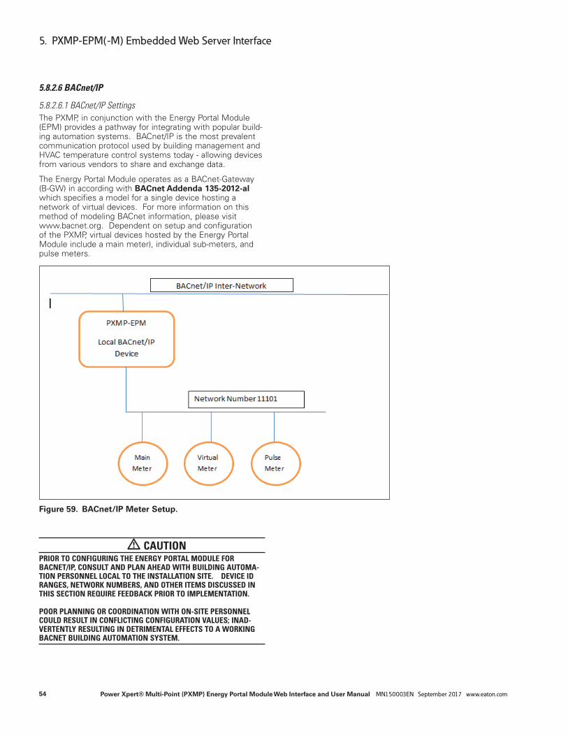
5.8.2.6 BACnet/IP
5.8.2.6.1 BACnet/IP SettingsThe PXMP, in conjunction with the Energy Portal Module (EPM) provides a pathway for integrating with popular build-ing automation systems. BACnet/IP is the most prevalent communication protocol used by building management and HVAC temperature control systems today - allowing devices from various vendors to share and exchange data.
The Energy Portal Module operates as a BACnet-Gateway (B-GW) in according with BACnet Addenda 135-2012-al which specifies a model for a single device hosting a network of virtual devices. For more information on this method of modeling BACnet information, please visit www.bacnet.org. Dependent on setup and configuration of the PXMP, virtual devices hosted by the Energy Portal Module include a main meter), individual sub-meters, and pulse meters.
Figure 59. BACnet/IP Meter Setup.
m CAUTIONPRIOR TO CONFIGURING THE ENERGY PORTAL MODULE FOR BACNET/IP, CONSULT AND PLAN AHEAD WITH BUILDING AUTOMA-TION PERSONNEL LOCAL TO THE INSTALLATION SITE. DEVICE ID RANGES, NETWORK NUMBERS, AND OTHER ITEMS DISCUSSED IN THIS SECTION REQUIRE FEEDBACK PRIOR TO IMPLEMENTATION. POOR PLANNING OR COORDINATION WITH ON-SITE PERSONNEL COULD RESULT IN CONFLICTING CONFIGURATION VALUES; INAD-VERTENTLY RESULTING IN DETRIMENTAL EFFECTS TO A WORKING BACNET BUILDING AUTOMATION SYSTEM.

55
5. PXMP-EPM(-M) Embedded Web Server Interface
Power Xpert® Multi-Point (PXMP) Energy Portal Module Web Interface and User Manual MN150003EN September 2017 www.eaton.com
Configuring the Energy Portal Module for BACnet involves accessing Comms>BACnet/IP >BACnet/IP Settings from the WebUI. Table 7 provides a detail on each parameter and helpful configuration notes.
Figure 60. BACnet/IP Edit.
Table 7. BACnet/IP Parameter Details
Parameter Notes Possible Values
Enable BACnet/IP Check-box for enabling BACnet/IP fieldbus communications. A checkmark present indicates BACnet/IP has been enabled
- BACnet/IP Disabled - BACnet/IP Enabled
Identification
Base ID for Auto-Assign Assigns a Base Number for auto-numbering of BACnet Virtual Devices Hosted by the Energy Portal Module.
0 – 4194000
Auto-assign Network Card ID Indicates if the BACnet Device ID for the local Energy Portal Module device will be automati-cally assigned based on the Base ID for Auto-Assign Value. A checkmark present indicates that the BACnet Device ID for the Energy Portal Module will be automatically assigned in sequential order per the Base ID for Auto-Assign parameter. No checkmark present indicates that the BACnet Device ID for the Energy Portal Module must be manually defined.
- Manual Assignment - Automatic Assignment
Network Card
Device ID (object-identifier) Reflects the BACnet Device ID for the Energy Portal Module. This value will be read-only when Auto-assign Network Card ID is checked. Otherwise, set the Device ID uniquely.
0-4194302
Device object-name Reflects the Device object name for the Energy Portal Module when discovered/learned by a BACnet operator workstation or advanced workstation. This value can be assigned any unique string of ANSI-based characters.
32 characters maximum
BACnet/IP MAC Address Reflects the MAC Address for the Energy Portal Module. This is read-only and is based on the IP address assigned to the card.
MAC Address Pattern

56
5. PXMP-EPM(-M) Embedded Web Server Interface
Power Xpert® Multi-Point (PXMP) Energy Portal Module Web Interface and User Manual MN150003EN September 2017 www.eaton.com
Parameter Notes Possible Values
BBMD
IP v4 Address for Foreign Registration
Defines the IP address of a BBMD that the Energy Portal Module can register with for foreign device communications with a remote BACnet inter-network.
BBMD Time to Live Defines the amount of time, in seconds, that the Energy Portal Module will maintain a valid registration with a BBMD or Foreign Device Registrar. Eaton recommends a time of 360 seconds (6 minutes). It is recommended that you consult your BACnet Building Maintenance personnel for guidance on configuration of this parameter.
1-65534
Virtual Routing
Routed Network Number Defines the Network Number assignment. The Energy Portal Module must have a unique net-work number assigned to it that cannot conflict with any other established BACnet networks (IP, Ethernet, MSTP, PTP, etc..).
1-65534
MAC template for Virtual Devices Defines the MAC Address Scheme automatically assigned to virtual devices hosted by the Energy Portal Module. Any valid IP address format can be assigned to this field. For ease of configuration, Eaton recommends a MAC Template IP address configuration of 1.1.168.0
5.8.2.6.2 BACnet/IP EPICS FileOnce you have configured your BACnet/IP Settings, you can verify assigned Device IDs, Device Names, and MAC Addresses from the BACnet/IP Epics File page. This page is located underneath the BACnet/IP Settings page within the Web User Interface.
Figure 61. BACnet/IP Epics File.
Users can download a copy of the BACnet objects that reside in each virtual device by placing a check in the Download Epic File column for the corresponding device. Once checked, a button named Generate and View EPICS File will appear at the bottom of the page. This permits the download of the file(s) for device(s) selected.

57
5. PXMP-EPM(-M) Embedded Web Server Interface
Power Xpert® Multi-Point (PXMP) Energy Portal Module Web Interface and User Manual MN150003EN September 2017 www.eaton.com
5.8.2.7 Web Service Setup for Power Xpert Insight (PXI) SoftwareThe Web Service Setup screen (Figure 62) allows the Facility Manager to enable/disable and specify web services trend update interval, to enable/disable web services alarm notification.
Figure 62. Web Service Setup Screen.

58
5. PXMP-EPM(-M) Embedded Web Server Interface
Power Xpert® Multi-Point (PXMP) Energy Portal Module Web Interface and User Manual MN150003EN September 2017 www.eaton.com
Figure 63. Install CA Certificate Page.
2. Click the Root CA Certificate link.
3. Click the Open button.
Figure 64. File Download Dialog Box.
5.8.2.8 Root Certificate Authority InstallationImprove the security of your Power Xpert Meter on the Web by installing a root certificate authority (CA). A CA is a trusted third-party organization that issues digital certificates for use with encrypted digital transactions. The digital cer-tificate guarantees that the company holding a certificate is who it claims to be.
You can use the meter without installing a root CA (using http), but the transactions will not be as secure as with the root CA (using https). The performance of the meter is not impacted by using secure transactions.
This section explains root CA installation for:
●● Microsoft Internet Explorer 11
●● Google Chrome
●● Mozilla Firefox
●● Edge
●● Safari
Installing Root CA with Microsoft Internet Explorer 11To install a certificate for the Power Xpert Meter with Microsoft Internet Explorer 11:
1. Open the browser and type the IP address of the meter followed by the path “/ca.html” in the address bar. For example: https://192.168.1.1/ca.html The install CA certificate page appears.
59
5. PXMP-EPM(-M) Embedded Web Server Interface
Power Xpert® Multi-Point (PXMP) Energy Portal Module Web Interface and User Manual MN150003EN September 2017 www.eaton.com
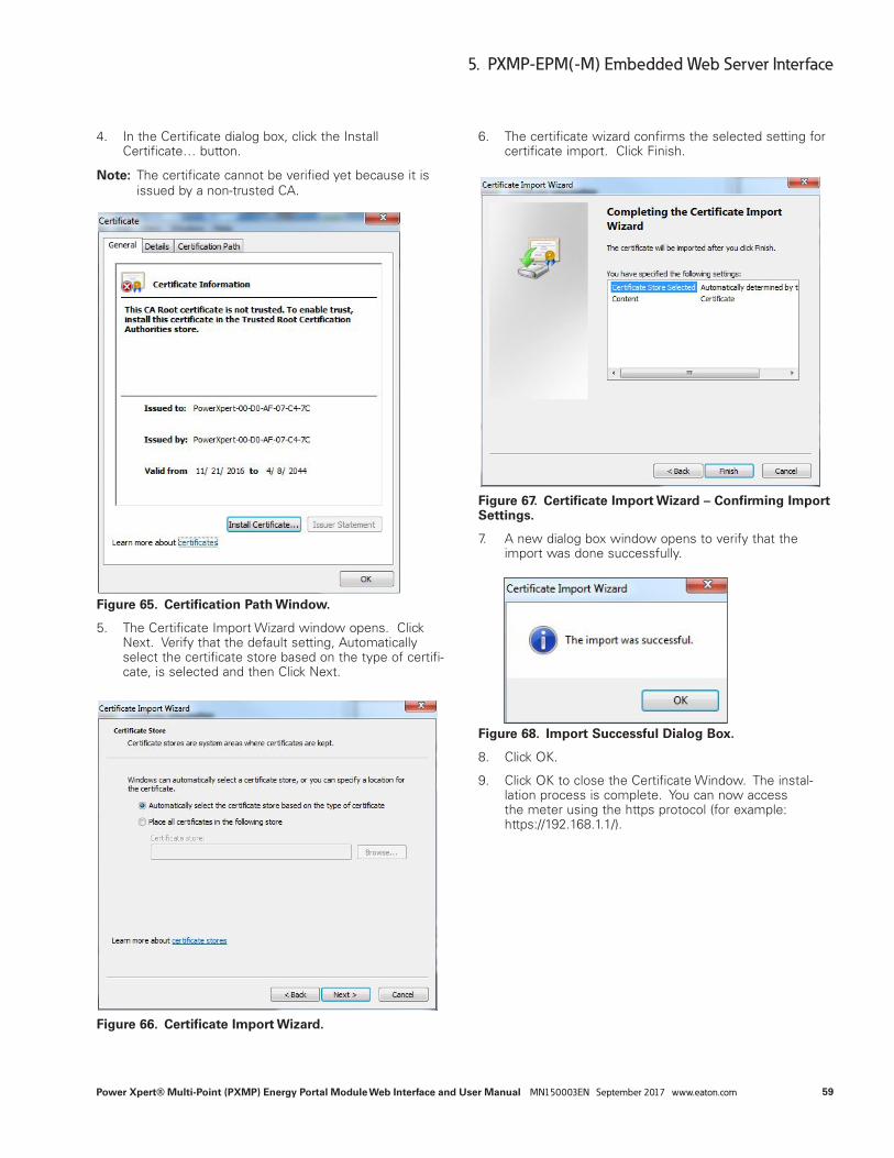
4. In the Certificate dialog box, click the Install Certificate… button.
ote:N The certificate cannot be verified yet because it is issued by a non-trusted CA.
Figure 65. Certification Path Window.
5. The Certificate Import Wizard window opens. Click Next. Verify that the default setting, Automatically select the certificate store based on the type of certifi-cate, is selected and then Click Next.
Figure 66. Certificate Import Wizard.
6. The certificate wizard confirms the selected setting for certificate import. Click Finish.
Figure 67. Certificate Import Wizard – Confirming Import Settings.
7. A new dialog box window opens to verify that the import was done successfully.
Figure 68. Import Successful Dialog Box.
8. Click OK.
9. Click OK to close the Certificate Window. The instal-lation process is complete. You can now access the meter using the https protocol (for example: https://192.168.1.1/).

60
5. PXMP-EPM(-M) Embedded Web Server Interface
Power Xpert® Multi-Point (PXMP) Energy Portal Module Web Interface and User Manual MN150003EN September 2017 www.eaton.com
Installing Root CA with Google ChromeTo install a certificate for the Power Xpert Meter with Google Chrome:
1. Open the browser and type the IP address of the meter followed by the path “/ca.html” in the address bar. For example: https://192.168.1.1/ca.html The install CA certificate page appears (see Figure 63).
2. Click the Root CA Certificate link.
3. Click the Open button (see Figure 64).
4. In the Certificate dialog box, click the Install Certificate… button (see Figure 65).
ote:N The certificate cannot be verified yet because it is issued by a non-trusted CA.
5. The Certificate Import Wizard window opens. Click Next. Verify that the default setting, Automatically select the certificate store based on the type of certifi-cate, is selected and then Click Next (see Figure 66).
6. The certificate wizard confirms the selected setting for certificate import. Click Finish (see Figure 67).
7. A new dialog box window opens to verify that the import was done successfully (see Figure 68).
8. Click OK.
9. Click OK to close the Certificate Window. The instal-lation process is complete. You can now access the meter using the https protocol (for example: https://192.168.1.1/).
Installing Root CA with Mozilla FirefoxTo install a certificate for the Power Xpert Meter with Mozilla Firefox:
1. Open the browser and type the IP address of the meter followed by the path “/ca.html” in the address bar. For example: https://192.168.1.1/ca.html. The install CA certificate page appears.
Figure 69. Install CA Certificate Page.

61
5. PXMP-EPM(-M) Embedded Web Server Interface
Power Xpert® Multi-Point (PXMP) Energy Portal Module Web Interface and User Manual MN150003EN September 2017 www.eaton.com
2. Click the Root CA Certificate link. Firefox opens the Downloading Certificate window.
3. Click the Trust this CA to identify web sites check box option.
Figure 70. Downloading Certificate Window.
4. Click OK to complete the installation process. The installation process is complete. You can now access the meter using the https protocol (for example, https://192.168.1.1/ca.html).
Installing Root CA with EdgeTo install a certificate for the Power Xpert Meter with Edge:
1. Open the browser and type the IP address of the meter followed by the path “/ca.html” in the address bar. (For example: https://192.168.1.1/ca.html). The install CA certificate page appears.
Figure 71. Install CA Certificate Page.
2. Click the Root CA Certificate link.
3. Click the Open button.

62
5. PXMP-EPM(-M) Embedded Web Server Interface
Power Xpert® Multi-Point (PXMP) Energy Portal Module Web Interface and User Manual MN150003EN September 2017 www.eaton.com
Figure 72. File Download Dialog Box.
4. In the Certificate dialog box, click the Install Certificate… button.
ote:N Note: The certificate cannot be verified yet because it is issued by a non-trusted CA.
Figure 73. Certification Path Window.
5. The Certificate Import Wizard window opens. Verify that the default setting, Current User, is selected and then Click Next.
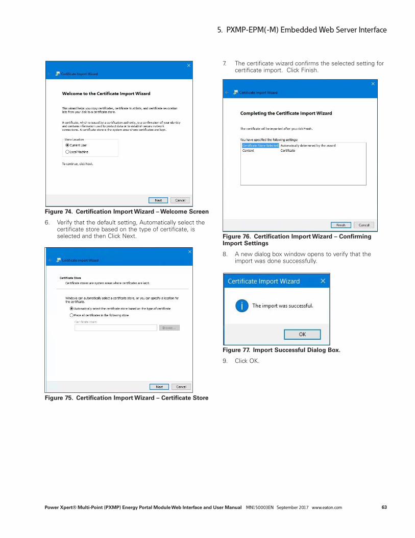
63
5. PXMP-EPM(-M) Embedded Web Server Interface
Power Xpert® Multi-Point (PXMP) Energy Portal Module Web Interface and User Manual MN150003EN September 2017 www.eaton.com
Figure 74. Certification Import Wizard – Welcome Screen
6. Verify that the default setting, Automatically select the certificate store based on the type of certificate, is selected and then Click Next.
Figure 75. Certification Import Wizard – Certificate Store
7. The certificate wizard confirms the selected setting for certificate import. Click Finish.
Figure 76. Certification Import Wizard – Confirming Import Settings
8. A new dialog box window opens to verify that the import was done successfully.
Figure 77. Import Successful Dialog Box.
9. Click OK.

64
5. PXMP-EPM(-M) Embedded Web Server Interface
Power Xpert® Multi-Point (PXMP) Energy Portal Module Web Interface and User Manual MN150003EN September 2017 www.eaton.com
In the Web Service Setup Edit page (see Figure 78), the Facility Manager may enable web services trend update by selecting an update interval from the following three choices:
●● 5 Minutes;
●● 15 Minutes; or
●● 60 Minutes.
Selecting the “None” option on the Web Service Setup page will disable web services trend update.
The web services alarm notification can be turned on or off by checking or unchecking the box next to the “Enable Web Services Alarm Notification.”
Figure 78. Web Service Setup Edit Page.

65
5. PXMP-EPM(-M) Embedded Web Server Interface
Power Xpert® Multi-Point (PXMP) Energy Portal Module Web Interface and User Manual MN150003EN September 2017 www.eaton.com
5.8.3 Diagnostics InformationThe Facility Manager can view the system log, commu-nications status and connections by clicking on the Diagnostics screen. The Facility Manager can also reset the system log.
5.8.3.1 System LogA system log stores system information in the PXMP-MB. The PXMP-EPM(-M) retrieves the system information from the PXMP-MB in the background, and stores them in the PXMP-EPM(-M)’s non-volatile memory. The System Log screen provides a list of past events and the time associ-ated with each event (see Figure 79). The Facility Manager can copy all existing system log entries to clipboard by click-ing the “Copy All” button. Click the “Reset All” button will reset and clear all existing system log entries in the PXMP-EPM(-M).
Figure 79. System Log Screen.

66
5. PXMP-EPM(-M) Embedded Web Server Interface
Power Xpert® Multi-Point (PXMP) Energy Portal Module Web Interface and User Manual MN150003EN September 2017 www.eaton.com
5.8.3.2 Communication
5.8.3.2.1 Ethernet StatusThe Ethernet Status screen (also see Section 5.2.2.1 - Figure 6) shows Ethernet-related status information. The screen is divided into two sections. The IP address, subnet mask, and default gateway are shown in the first section. Such information may be used by the Facility Manager and Tenant(s) to remotely login into the PXMP-EPM(-M) web server.
The media access control (MAC) addresses and link status are given in the second section. Both the MAC address of
the LAN/WAN Ethernet port and the MAC address of the local Ethernet port are listed along with their link status. For example, as shown in Figure 6, the LAN/WAN Ethernet port has a MAC address of 00:D0:AF:07:AF:05, and the local Ethernet port has a MAC address of 00:D0:AF:07:AF:04. Both ports’ Ethernet links are active.
5.8.3.2.2 Local N/W StatusThe Local Network (N/W) Status screen (see Figure 80) shows detailed information about the local Ethernet port. The screen is for display information only, and cannot be edited.
Figure 80. Local N/W Status Screen.

67
5. PXMP-EPM(-M) Embedded Web Server Interface
Power Xpert® Multi-Point (PXMP) Energy Portal Module Web Interface and User Manual MN150003EN September 2017 www.eaton.com
5.8.3.2.3 LAN Port StatusThe LAN Port Status screen (see Figure 81) shows detailed information about the LAN/WAN Ethernet port. The screen is for display information only, and cannot be edited.
Figure 81. LAN Port Status Screen.

68
5. PXMP-EPM(-M) Embedded Web Server Interface
Power Xpert® Multi-Point (PXMP) Energy Portal Module Web Interface and User Manual MN150003EN September 2017 www.eaton.com
5.8.3.2.4 COM StatusThe COM Status page (see Figure 82) shows detailed infor-mation about the communications status. The page is for display information only, and cannot be edited.
Figure 82. COM Status Page.

69
6 PXMP-EPM(-M) Secure FTP Service
Power Xpert® Multi-Point (PXMP) Energy Portal Module Web Interface and User Manual MN150003EN September 2017 www.eaton.com
6 PXMP-EPM(-M) Secure FTP Service
The PXMP-EPM(-M) is equipped with 4 GB of non-volatile memory and is capable of storing up to 10 years of load profile data at 15-minute interval. The PXMP-EPM(-M) uses secure file transfer protocol (SFTP) to provide access, transfer, and management functionalities to the stored load profile data and other information. Both SFTP commands and data are encrypted to prevent Passwords and sensitive information from being transmitted openly over the network.
6.1 Client Access to PXMP-EPM(-M) SFTP ServiceTo access the PXMP-EPM(-M) SFTP service, an SFTP client is needed. An SFTP client is a software program that uses secure shell (SSH) network protocol to access, transfer and manage files. SFTP clients with graphical user interface for Microsoft Windows include WinSCP and Filezilla. Other command-line SFTP clients include sftp and psftp.
Access to PXMP-EPM(-M) SFTP service is illustrated in this manual using a WinSCP client. A copy of the WinSCP client may be obtained from http://winscp.net/eng/download.php.
Figure 83 shows a WinSCP Login screen. The information needed to log into the PXMP-EPM(-M) SFTP service is listed in Table 8
Figure 83. WinSFTP Login Screen.
Table 8. SFTP Login Information.
File Protocol Supported file transfer protocols. Select SFTP to access PXMP-EPM(-M) SFTP Service.
Host Name PXMP-EPM(-M) Ethernet/LAN IP address. See Section 5.2.1.1 on how to obtain PXMP-EPM(-M) Ethernet/LAN IP address.
Port Number PXMP-EPM(-M) SFTP service uses port 2222.
Username PXMP-EPM(-M) SFTP service uses “ftp” (without quotation marks) as Username.
Password PXMP-EPM(-M) SFTP service uses “ftp” (without quotation marks) as default Password. See Section 5.9.2.1 on how to change the SFTP default Password.
ote:N The PXMP-EPM(-M) SFTP service uses port 2222. This is different from conventional FTP services that use port 22 for connection.

70
6 PXMP-EPM(-M) Secure FTP Service
Power Xpert® Multi-Point (PXMP) Energy Portal Module Web Interface and User Manual MN150003EN September 2017 www.eaton.com
Upon a successful login, the User gains access to the ener-gy and trend folders in the PXMP-EPM(-M) (see Figure 84).
Figure 84. PXMP-EPM(-M) SFTP Folders.
6.2 SFTP Folders and FilesThe PXMP-EPM(-M) stores metered data in two separate folders. The energy folder contains load profile data, and the trend folder contains minimum, maximum, and average values of metered data at five-minute intervals.
6.2.1 SFTP Energy Folder and FilesThe energy folder contains load profile data files. The load profile data files are partitioned into groups and stored in separate files. In addition, data for pulse meters are stored in an individual file (see Figure 85).
Figure 85. PXMP-EPM(-M) SFTP Energy Folder.

71
6 PXMP-EPM(-M) Secure FTP Service
Power Xpert® Multi-Point (PXMP) Energy Portal Module Web Interface and User Manual MN150003EN September 2017 www.eaton.com
Each file contains metered data in comma-separated values (CSV) format. Table 9 describes the contents of each file.
Forward Energy is watt-hours being delivered from the util-ity to the load. Reverse Energy is watt-hours being delivered to the utility from the load.
Table 9. Energy Folder Filenames and Contents
Filename Content
PXMP_ForwardEnergy_LP_FW_YYMMDD.csv1 Forward kW demand (import)
PXMP_ReverseEnergy_LP_RW_YYMMDD.csv Reverse kW demand (export)
PXMP_Energy_LP_Q1_YYYYMMDD.csv Q1 kVAR demand (inductive/motor load)
PXMP_Energy_LP_Q2_YYYYMMDD.csv Q2 kVAR demand (inductive generator)
PXMP_Energy_LP_Q3_YYYYMMDD.csv Q3 kVAR demand (capacitive generator)
PXMP_Energy_LP_Q4_YYYYMMDD.csv Q4 kVAR demand (capacitive load)
PXMP_Energy_LP_Q1Q4_YYYYMMDD.csv Q1 and Q4 KVA demand (import)
PXMP_Energy_LP_Q2Q3_YYYYMMDD.csv Q2 and Q3 KVA demand (export)
PXMP_Pulse_LP_YYYYMMDD.csv Data for pulse meters1 YYYY: 4-digit year; MM: 2-digit month; DD: 2-digit day.
6.2.1.1 Load Profile Data FilesTable 10 shows an example of contents of a sample load profile data file “PXMP_Power_LP_FW_20131108.csv.” The rows provide time-stamped load profile data records, and the columns give channel-related information. According to Table 9, the sample load profile data file contains forward demand values in kilowatts. Similarly, load profile data file “PXMP_Energy_LP_Q2_20131108.csv” contains Q2 demand (inductive generator) in kVARs, and load profile data file “PXMP_Energy_LP_Q2Q3_20131108.csv” contains Q2 and Q3 demand (export) in kVAs.
Table10. Energy Load Profile Data File.
Date Time RTP 0 1 2 … 59 60
Main Meter Office Lab … HVAC N/A
12/1/2013 0:00 0 63.039 3.389 2.368 … 35.522 0
12/1/2013 0.01 1 63.495 3.428 2.377 … 35.821 0
12/1/2013 0.02 1 63.599 3.426 2.402 … 35.892 0
⁞ ⁞ ⁞ ⁞ ⁞ ⁞ ⁞ ⁞ ⁞
12/7/2013 23:58 0 63.311 3.411 2.377 … 35.596 0
12/7/2013 23:59 0 63.051 3.396 2.368 … 35.892 0
The first row of the load profile data file provides general header information, and the second row gives channel names. Load profile data records are listed starting from the third row. In the example shown in Table 10, the load profile is recorded at one-minute interval. Depending on the User’s selection, the load profile may be recorded at 5-, 10-, 15-, 30- or 60-minute interval. Each load profile data file contains up to seven days of data records.
The first column of the load profile data file gives the date of the data records. The second column provides time of the data records. The third column gives the real time pric
ing (RTP) information. The real time pricing information is a binary flag. For a given load profile data record, a “0” means that the real time pricing is disabled for the record, while a “1” indicates that the real time pricing is enabled.
The fourth column of the load profile data file is Channel 0, Main Meter. This channel is associated with the load profile data at the PXMP Meter Base. The 5th through the 64th columns list up to 60 channels of load profile data. If a channel is not defined or used, its load profile data records are filled with zeros. In the example shown in Table 10, Channel 60 is not defined, and its corresponding load profile data records are filled with zeros.
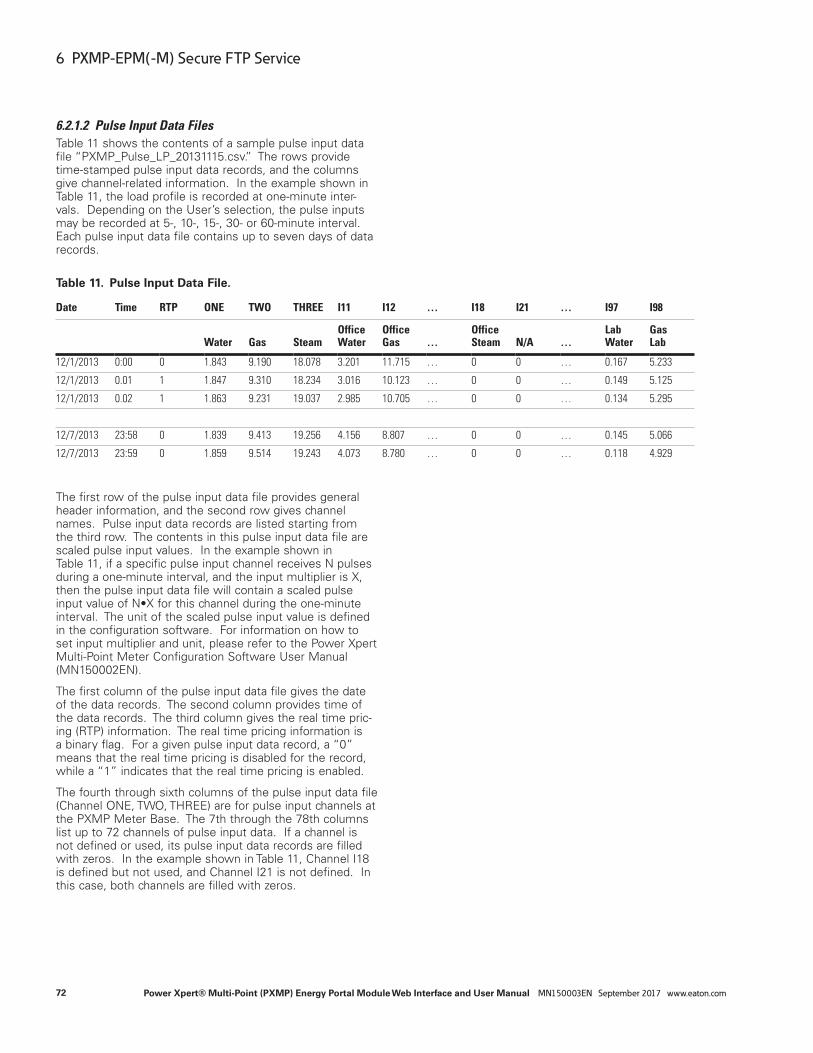
72
6 PXMP-EPM(-M) Secure FTP Service
Power Xpert® Multi-Point (PXMP) Energy Portal Module Web Interface and User Manual MN150003EN September 2017 www.eaton.com
6.2.1.2 Pulse Input Data FilesTable 11 shows the contents of a sample pulse input data file “PXMP_Pulse_LP_20131115.csv.” The rows provide time-stamped pulse input data records, and the columns give channel-related information. In the example shown in Table 11, the load profile is recorded at one-minute inter-vals. Depending on the User’s selection, the pulse inputs may be recorded at 5-, 10-, 15-, 30- or 60-minute interval. Each pulse input data file contains up to seven days of data records.
Table 11. Pulse Input Data File.
Date Time RTP ONE TWO THREE I11 I12 … I18 I21 … I97 I98
Water Gas SteamOffice Water
Office Gas …
Office Steam N/A …
Lab Water
Gas Lab
12/1/2013 0:00 0 1.843 9.190 18.078 3.201 11.715 … 0 0 … 0.167 5.233
12/1/2013 0.01 1 1.847 9.310 18.234 3.016 10.123 … 0 0 … 0.149 5.125
12/1/2013 0.02 1 1.863 9.231 19.037 2.985 10.705 … 0 0 … 0.134 5.295
⁞ ⁞ ⁞ ⁞ ⁞ ⁞ ⁞ ⁞ ⁞ ⁞ ⁞ ⁞ ⁞ ⁞
12/7/2013 23:58 0 1.839 9.413 19.256 4.156 8.807 … 0 0 … 0.145 5.066
12/7/2013 23:59 0 1.859 9.514 19.243 4.073 8.780 … 0 0 … 0.118 4.929
The first row of the pulse input data file provides general header information, and the second row gives channel names. Pulse input data records are listed starting from the third row. The contents in this pulse input data file are scaled pulse input values. In the example shown in Table 11, if a specific pulse input channel receives N pulses during a one-minute interval, and the input multiplier is X, then the pulse input data file will contain a scaled pulse input value of N•X for this channel during the one-minute interval. The unit of the scaled pulse input value is defined in the configuration software. For information on how to set input multiplier and unit, please refer to the Power Xpert Multi-Point Meter Configuration Software User Manual (MN150002EN).
The first column of the pulse input data file gives the date of the data records. The second column provides time of the data records. The third column gives the real time pric-ing (RTP) information. The real time pricing information is a binary flag. For a given pulse input data record, a “0” means that the real time pricing is disabled for the record, while a “1” indicates that the real time pricing is enabled.
The fourth through sixth columns of the pulse input data file (Channel ONE, TWO, THREE) are for pulse input channels at the PXMP Meter Base. The 7th through the 78th columns list up to 72 channels of pulse input data. If a channel is not defined or used, its pulse input data records are filled with zeros. In the example shown in Table 11, Channel I18 is defined but not used, and Channel I21 is not defined. In this case, both channels are filled with zeros.

73
6 PXMP-EPM(-M) Secure FTP Service
Power Xpert® Multi-Point (PXMP) Energy Portal Module Web Interface and User Manual MN150003EN September 2017 www.eaton.com
6.2.2 SFTP Trend Folder and FilesThe trend folder provides minimum, maximum, and average values of metered data at five-minute intervals (see Figure 86). The trend data files are partitioned into groups and stored in separate files.
Figure 86. PXMP-EPM(-M) SFTP Trend Folder.
Each file contains metered data in CSV format. Table 12 describes the contents of each file.
Table 12. Trend Folder Filenames and Contents.
Filename Content
Trend_Aggregate_Meter_YYYYMMDD.csv Aggregate meter data
Trend_Virtual_Meter_Watt_YYYYMMDD.csv Virtual meter real power in watts
Trend_Virtual_Meter_Var_YYYYMMDD.csv Virtual meter reactive power in vars
Trend_Virtual_Meter_VA_YYYYMMDD.csv Virtual meter apparent power in V•As
Trend_Virtual_Meter_PF_YYYYMMDD.csv Virtual meter power factor

74
6 PXMP-EPM(-M) Secure FTP Service
Power Xpert® Multi-Point (PXMP) Energy Portal Module Web Interface and User Manual MN150003EN September 2017 www.eaton.com
6.2.2.1 Aggregate Meter Data FilesTable 13 shows contents of a sample aggregate meter data file “Trend_Aggregate_Meter_20131121.csv.” The rows pro-vide time-stamped aggregate meter data, and the columns give channel-related information.
Table 13. Aggregate Meter Data File.
Date Time Ia(avg) Ia(min) Ia(max) … Ptotal(avg) … Vab(min) … Fsys(max) … PFc(max)
12/9/2013 0:00 122.141 119.672 138.281 … 63400.802 … 206.338 … 59.999 … 1.000
12/9/2013 0.05 123.882 124.841 133.614 … 63399.521 … 206.339 … 59.998 … 0.999
12/9/2013 0.10 124.674 121.945 133.626 … 63399.760 … 206.341 … 59.999 … 1.000
⁞ ⁞ ⁞ ⁞ ⁞ ⁞ ⁞ ⁞ ⁞ ⁞ ⁞ ⁞ ⁞12/9/2013 23:50 122.545 124.717 134.668 … 63399.420 … 206.336 … 59.999 … 1.000
12/9/2013 23:55 124.042 121.754 135.733 … 63401.003 … 206.341 … 60.000 … 1.000
The first row of the aggregate meter data file provides gen-eral header information. Aggregate meter data records are listed starting from the second row. The meter data are recorded at a five-minute interval. Each aggregate meter data file contains up to 24 hours of data records.
The first column of the aggregate meter data file gives the date of the data records. The second column provides time of the data records. Starting from the third column, quanti-ties listed in Table 14 are recorded with their respective minimum, maximum and average values.
Table 14. Aggregate Meter Data Contents.
Name Description
Ia, Ib, Ic Current in phase a, b, c (in amperes)
Pa, Pb, Pc Real power in phase a, b, c (in watts)
Ptotal Three-phase total real power (in watts)
Qa, Qb, Qc Reactive power in phase a, b, c (in Vars)
Qtotal Three-phase total reactive power (in Vars)
Sa, Sb, Sc Apparent power in phase a, b, c (in VAs)
Stotal Three-phase total apparent power (in VAs)
Van, Vbn, Vcn Line-neutral voltages (in volts)
Vab, Vbc, Vca Line-line voltages (in volts)
Fsys System frequency (in hertz)
PFsys System power factor
Temperature PXMP-EPM(-M) temperature (in degrees Celsius)
PFa, PFb, PFc Power factor in phase a, b, c

75
6 PXMP-EPM(-M) Secure FTP Service
Power Xpert® Multi-Point (PXMP) Energy Portal Module Web Interface and User Manual MN150003EN September 2017 www.eaton.com
6.2.2.2 Virtual Meter Data FilesTable 15 shows contents of a sample virtual meter data file “Trend_Virtual_Meter_Watt_20131121.csv.” The rows provide time-stamped virtual meter data records, and the columns give channel-related information.
Table 15. Virtual Meter Data File.
Date TimeMeter_01 _Watt(avg)
Meter_01 _Watt(min)
Meter_01 _Watt(max) …
Meter_60 _Watt(avg)
Meter_60 _Watt(min)
Meter_60 _Watt(max)
12/9/2013 0:00 3415.848 3415.231 3416.952 … 17894.994 17891.160 17898.889
12/9/2013 0.05 3415.829 3415.366 3416.483 … 17894.650 17891.275 17897.750
12/9/2013 0.10 3415.961 3415.186 3416.781 … 17894.508 17891.521 17897.578
⁞ ⁞ ⁞ ⁞ ⁞ ⁞ ⁞ ⁞ ⁞12/9/2013 23:50 3415.887 3415.186 3416.564 … 17894.520 17891.637 17898.645
12/9/2013 23:55 3415.948 3415.132 3416.655 … 17894.914 17890.656 17898.889
The first row of the virtual meter data file provides general header information. Virtual meter data records are listed starting from the second row. The meter data is recorded at a five-minute interval. Each virtual meter data file contains up to 24 hours of data records.
The first column of the virtual meter data file gives the date of the data records. The second column provides time of the data records. The 3rd through the 182nd columns list up to 60 channels of virtual meter data with their respective minimum, maximum, and average values. If a channel is not defined or used, its virtual meter data records are filled with zeros.

76
Appendix A Specifications
Power Xpert® Multi-Point (PXMP) Energy Portal Module Web Interface and User Manual MN150003EN September 2017 www.eaton.com
Appendix A Specifications
General Specifications:●● Operational Temperature Range -20 to 70°C (-4 to 158°F)
●● Storage Temperature Range -40 to 85°C (-40 to 185°F)
●● Elevation 0-9,849 ft. (0-3000 m)
●● Humidity 5-95%, non-condensing environment
●● Housing IP20 when installed in PXMP-MB and cables inserted into connectors
●● Pollution Degree 2
●● CE Mark
●● EMC EN61326
●● Emissions conducted and radiated as part of PXMP Meter System.
●● FCC Part 15 Class B
●● CISPR 11 Class B
●● Product Safety:
●● IEC/EN61010-1
●● UL61010-1 File E185559
●● CNL Evaluation to CAN/C22.2 No 1010.1.92
●● PXMP-MB (-AB) Meter Base slot position ‘10’ only
●● Internal Memory 4GB NAND Flash
●● For Energy/Demand profiles, trending and general logs
●● Web Services
●● Up to five simultaneous clients
Communication Ports: ●● Configuration Ethernet RJ45 Cat5 STP/UTP
●● 10 Base T/100 Base Tx
●● Auto Cross-over Capability supported.
●● Java Web Browser interface
●● IP address 192.168.1.1 by default
●● Bottom Facing LAN/WAN Ethernet Port
●● RJ45 Cat5 STP/UTP 10 Base T/100 Base Tx
●● STP required for full electromagnetic immunity
●● Auto Cross-over capability supported.
●● Supports Modbus TCP and Java Web Browser interface
●● DHCP by default
●● Bottom Facing Telephone Modem Interface
●● V.92 Modem
●● RJ11 field interface
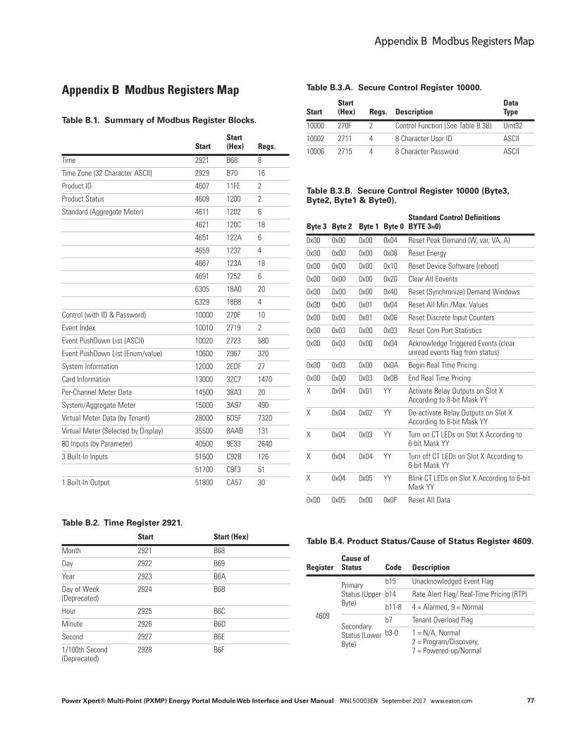
77
Appendix B Modbus Registers Map
Power Xpert® Multi-Point (PXMP) Energy Portal Module Web Interface and User Manual MN150003EN September 2017 www.eaton.com
Appendix B Modbus Registers Map
Table B.1. Summary of Modbus Register Blocks.
StartStart (Hex) Regs.
Time 2921 B68 8
Time Zone (32 Character ASCII) 2929 B70 16
Product ID 4607 11FE 2
Product Status 4609 1200 2
Standard (Aggregate Meter) 4611 1202 6
4621 120C 18
4651 122A 6
4659 1232 4
4667 123A 18
4691 1252 6
6305 18A0 20
6329 18B8 4
Control (with ID & Password) 10000 270F 10
Event Index 10010 2719 2
Event PushDown List (ASCII) 10020 2723 580
Event PushDown List (Enum/value) 10600 2967 320
System Information 12000 2EDF 27
Card Information 13000 32C7 1470
Per-Channel Meter Data 14500 38A3 20
System/Aggregate Meter 15000 3A97 490
Virtual Meter Data (by Tenant) 28000 6D5F 7320
Virtual Meter (Selected by Display) 35500 8AAB 131
80 Inputs (by Parameter) 40500 9E33 2640
3 Built-In Inputs 51500 C92B 126
51700 C9F3 51
1 Built-In Output 51800 CA57 30
Table B.2. Time Register 2921.
Start Start (Hex)
Month 2921 B68
Day 2922 B69
Year 2923 B6A
Day of Week (Deprecated)
2924 B6B
Hour 2925 B6C
Minute 2926 B6D
Second 2927 B6E
1/100th Second (Deprecated)
2928 B6F
Table B.3.A. Secure Control Register 10000.
StartStart (Hex) Regs. Description
Data Type
10000 270F 2 Control Function (See Table B.3B) Uint32
10002 2711 4 8 Character User ID ASCII
10006 2715 4 8 Character Password ASCII
Table B.3.B. Secure Control Register 10000 (Byte3, Byte2, Byte1 & Byte0).
Byte 3 Byte 2 Byte 1 Byte 0Standard Control Definitions BYTE 3=0)
0x00 0x00 0x00 0x04 Reset Peak Demand (W, var, VA, A)
0x00 0x00 0x00 0x08 Reset Energy
0x00 0x00 0x00 0x10 Reset Device Software (reboot)
0x00 0x00 0x00 0x20 Clear All Eevents
0x00 0x00 0x00 0x40 Reset (Synchronize) Demand Windows
0x00 0x00 0x01 0x04 Reset All Min./Max. Values
0x00 0x00 0x01 0x06 Reset Discrete Input Counters
0x00 0x03 0x00 0x03 Reset Com Port Statistics
0x00 0x03 0x00 0x04 Acknowledge Triggered Events (clear unread events flag from status)
0x00 0x03 0x00 0x0A Begin Real Time Pricing
0x00 0x00 0x03 0x0B End Real Time Pricing
X 0x04 0x01 YY Activate Relay Outputs on Slot X According to 8-bit Mask YY
X 0x04 0x02 YY De-activate Relay Outputs on Slot X According to 8-bit Mask YY
X 0x04 0x03 YY Turn on CT LEDs on Slot X According to 6-bit Mask YY
X 0x04 0x04 YY Turn off CT LEDs on Slot X According to 6-bit Mask YY
X 0x04 0x05 YY Blink CT LEDs on Slot X According to 6-bit Mask YY
0x00 0x05 0x00 0x0F Reset All Data
Table B.4. Product Status/Cause of Status Register 4609.
RegisterCause of Status Code Description
4609
Primary Status (Upper Byte)
b15 Unacknowledged Event Flag
b14 Rate Alert Flag/ Real-Time Pricing (RTP)
b11-8 4 = Alarmed, 9 = Normal
Secondary Status (Lower Byte)
b7 Tenant Overload Flag
b3-0 1 = N/A, Normal 2 = Program/Discovery, 7 = Powered-up/Normal

78
Appendix B Modbus Registers Map
Power Xpert® Multi-Point (PXMP) Energy Portal Module Web Interface and User Manual MN150003EN September 2017 www.eaton.com
Table B.5. Cause of Status Register 4610.
RegisterCause of Status Code Description
4610
Meter ID (Upper Byte)
If the Tenant Overload Flag is set, this byte indicates the associated MeterID.
If more than 1 Overload is active, the byte is FF (255)
Otherwise the byte is 00
Cause of Status (Lower Byte)
0 N/A
1 Normal
11 Overvoltage
12 Undervoltage
18 Voltage Unbalance
23 System Power
26 Watt or Watt Demand
27 VA or VA Demand
28 VAR or VAR Demand
70 Voltage Phase Loss (outage)
Table B.6. Aggregate Meter (Eaton Standard Registers).
StartStart (Hex)
Register Count Description TypeId Units
2921 0B68 8 Time (MM/DD/YY day HH:MM:SS 100th) (see Register 2921 Table B.2)
Uint16 Misc
4607 11FE 2 Product ID (constant, 0x200C)
Uint32
4609 1200 1 Primary/Secondary Status Uint16 Encoded
4610 1201 1 Cause-Of-Status Uint16 Encoded
4611 1202 2 IA Float Amps
4613 1204 2 IB Float Amps
4615 1206 2 IC Float Amps
4621 120C 2 Iavg Float Amps
4623 120E 2 VAB Float Volts
4625 1210 2 VBC Float Volts
4627 1212 2 VCA Float Volts
4629 1214 2 VLLavg Float Volts
4631 1216 2 VAN Float Volts
4633 1218 2 VBN Float Volts
4635 121A 2 VCN Float Volts
4637 121C 2 VLNavg Float Volts
Table B.6. Aggregate Meter (Eaton Standard Registers).
StartStart (Hex)
Register Count Description TypeId Units
4651 122A 2 Real Power (Watts) Float Watts
4653 122C 2 Reactive Power (Var) Float VAr
4655 122E 2 Apparent Power (VA) Float VA
4659 1232 2 Power Factor Float
4661 1234 2 Frequency Float Hz
4667 123A 2 Phase A Watts Float Watts
4669 123C 2 Phase B Watts Float Watts
4671 123E 2 Phase C Watts Float Watts
4673 1240 2 Phase A var Float Var
4675 1242 2 Phase B var Float Var
4677 1244 2 Phase C var Float Var
4679 1246 2 Phase A VA Float VA
4681 1248 2 Phase B VA Float VA
4683 124A 2 Phase C VA Float VA
4691 1252 2 Phase A PFa [Apparent\True Power Factor]
Float
4693 1254 2 Phase B PFa Float
4695 1256 2 Phase C PFa Float
6305 18A0 4 Forward Wh Energy 0.1 kWh
6309 18A4 4 Reverse Wh Energy 0.1 kWh
6313 18A8 4 Sum Total Wh Energy 0.1 kWh
6317 18AC 4 Delivered/Leading varh Energy 0.1 kvarh
6321 18B0 4 Received/Lagging varh Energy 0.1 kvarh
6329 18B8 4 VAh Energy 0.1 kVAh
Table B.7. System Information.
StartStart (Hex) Regs. SunSpec Name Description
12000 2EDF 10 Assembly Name (Meter Base)
20 characters (PXM-MB-AB)
12010 2EE9 6 Part Number 12 characters (66C2261G01)
12016 2EEF 1 Assembly Rev 2 characters
12017 2EF0 1 SubAssembly Rev (board) 2 characters
12018 2EF1 8 Serial Number 16 characters
(Cont.)

79
Appendix B Modbus Registers Map
Power Xpert® Multi-Point (PXMP) Energy Portal Module Web Interface and User Manual MN150003EN September 2017 www.eaton.com
Table B.8. Module Data.
StartStart (Hex) Regs.
Each up to 60 channels Description
13000 32C7 100 Assembly Name 20 characters x 10 cards
13100 332B 60 Part Number 12 characters x 10 cards (e.g. 66C2652G01)
13160 3367 20 Assembly Rev (2char), SubAssembly Rev (2char)
4 characters x 10 cards
13180 337B 80 Serial Number 16 characters x 10 cards
13390 344D 60 Associated meter (1-60)
16-bit unsigned integer x 10 cards x 6 channels
13450 3489 120 Load (% of Rating) IEEE 754 32-bit float x 10 cards x 6 channels
13570 3501 120 Current IEEE 754 32-bit float x 10 cards x 6 channels
13690 3579 120 Voltage IEEE 754 32-bit float x 10 cards x 6 channels
13810 35F1 120 Watts IEEE 754 32-bit float x 10 cards x 6 channels
13930 3669 120 var IEEE 754 32-bit float x 10 cards x 6 channels
14050 36E1 120 VA IEEE 754 32-bit float x 10 cards x 6 channels
14170 3759 120 PF IEEE 754 32-bit float x 10 cards x 6 channels
14290 37D1 60 CT ID (enumeration)
16-bit unsigned integer x 10 cards x 6 channels
14350 380D 120 CT Rating IEEE 754 32-bit float x 10 cards x 6 channels
Table B.9. Per-Channel Data.
StartStart (Hex) Regs. Each up to 60 meters Data Type
14500 38A3 1 Meter Card Selection (1-10) 16-bit unsigned integer
14501 38A4 1 Channel Selection (1-6) 16-bit unsigned integer
14502 38A5 1 Associated meter (1-60) 16-bit unsigned integer
14503 38A6 2 Load (% of Rating) IEEE 754 32-bit float
14505 38A8 2 Current IEEE 754 32-bit float
14507 38AA 2 Voltage IEEE 754 32-bit float
14509 38AC 2 Watts IEEE 754 32-bit float
14511 38AE 2 var IEEE 754 32-bit float
14513 38B0 2 VA IEEE 754 32-bit float
14515 38B2 2 PF IEEE 754 32-bit float
14517 38B4 1 CT ID (enumeration) 16-bit unsigned integer
14518 38B5 2 CT Rating IEEE 754 32-bit float x 10 cards x 6 channels
Table B.10. System/Aggregate Meter Data.
StartStart (Hex) Regs System Values Data Type
15000 3A97 2 Phase 1 Watts IEEE 754 32-bit float
15002 3A99 2 Phase 2 Watts IEEE 754 32-bit float
15004 3A9B 2 Phase 3 Watts IEEE 754 32-bit float
15006 3A9D 2 System Watts IEEE 754 32-bit float
15008 3A9F 2 Phase 1 var IEEE 754 32-bit float
15010 3AA1 2 Phase 2 var IEEE 754 32-bit float
15012 3AA3 2 Phase 3 var IEEE 754 32-bit float
15014 3AA5 2 System var IEEE 754 32-bit float
15016 3AA7 2 Phase 1 VA IEEE 754 32-bit float
15018 3AA9 2 Phase 2 VA IEEE 754 32-bit float
15020 3AAB 2 Phase 3 VA IEEE 754 32-bit float
15022 3AAD 2 System VA IEEE 754 32-bit float
15024 3AAF 2 V1 IEEE 754 32-bit float
15026 3AB1 2 V2 IEEE 754 32-bit float
15028 3AB3 2 V3 IEEE 754 32-bit float
15030 3AB5 2 Vab IEEE 754 32-bit float
15032 3AB7 2 Vbc IEEE 754 32-bit float
15034 3AB9 2 Vca IEEE 754 32-bit float
15036 3ABB 2 Freq IEEE 754 32-bit float
15038 3ABD 2 System PF IEEE 754 32-bit float
15040 3ABF 2 Temperature IEEE 754 32-bit float
15042 3AC1 2 Minimum Phase 1 Watts IEEE 754 32-bit float
15044 3AC3 2 Minimum Phase 2 Watts IEEE 754 32-bit float
15046 3AC5 2 Minimum Phase 3 Watts IEEE 754 32-bit float
15048 3AC7 2 Minimum System Watts IEEE 754 32-bit float
15050 3AC9 2 Minimum Phase 1 var IEEE 754 32-bit float
15052 3ACB 2 Minimum Phase 2 var IEEE 754 32-bit float
15054 3ACD 2 Minimum Phase 3 var IEEE 754 32-bit float
15056 3ACF 2 Minimum System var IEEE 754 32-bit float
15058 3AD1 2 Minimum Phase 1 VA IEEE 754 32-bit float
15060 3AD3 2 Minimum Phase 2 VA IEEE 754 32-bit float
15062 3AD5 2 Minimum Phase 3 VA IEEE 754 32-bit float
15064 3AD7 2 Minimum System VA IEEE 754 32-bit float
15066 3AD9 2 Minimum V1 IEEE 754 32-bit float
15068 3ADB 2 Minimum V2 IEEE 754 32-bit float
15070 3ADD 2 Minimum V3 IEEE 754 32-bit float
15072 3ADF 2 Minimum Vab IEEE 754 32-bit float
15074 3AE1 2 Minimum Vbc IEEE 754 32-bit float
15076 3AE3 2 Minimum Vca IEEE 754 32-bit float
15078 3AE5 2 Minimum Freq IEEE 754 32-bit float
15080 3AE7 2 Minimum System PF IEEE 754 32-bit float
15082 3AE9 2 Minimum Temperature IEEE 754 32-bit float

80
Appendix B Modbus Registers Map
Power Xpert® Multi-Point (PXMP) Energy Portal Module Web Interface and User Manual MN150003EN September 2017 www.eaton.com
Table B.10. System/Aggregate Meter Data.
StartStart (Hex) Regs System Values Data Type
15084 3AEB 2 Maximum Phase 1 Watts IEEE 754 32-bit float
15086 3AED 2 Maximum Phase 2 Watts IEEE 754 32-bit float
15088 3AEF 2 Maximum Phase 3 Watts IEEE 754 32-bit float
15090 3AF1 2 Maximum System Watts IEEE 754 32-bit float
15092 3AF3 2 Maximum Phase 1 var IEEE 754 32-bit float
15094 3AF5 2 Maximum Phase 2 var IEEE 754 32-bit float
15096 3AF7 2 Maximum Phase 3 var IEEE 754 32-bit float
15098 3AF9 2 Maximum System var IEEE 754 32-bit float
15100 3AFB 2 Maximum Phase 1 VA IEEE 754 32-bit float
15102 3AFD 2 Maximum Phase 2 VA IEEE 754 32-bit float
15104 3AFF 2 Maximum Phase 3 VA IEEE 754 32-bit float
15106 3B01 2 Maximum System VA IEEE 754 32-bit float
15108 3B03 2 Maximum Va IEEE 754 32-bit float
15110 3B05 2 Maximum Vb IEEE 754 32-bit float
15112 3B07 2 Maximum Vc IEEE 754 32-bit float
15114 3B09 2 Maximum Vab IEEE 754 32-bit float
15116 3B0B 2 Maximum Vbc IEEE 754 32-bit float
15118 3B0D 2 Maximum Vca IEEE 754 32-bit float
15120 3B0F 2 Maximum Freq IEEE 754 32-bit float
15122 3B11 2 Maximum System PF IEEE 754 32-bit float
15124 3B13 2 Maximum Temperature IEEE 754 32-bit float
15126 3B15 6 Min. Timestamp Phase 1 Watts
yyyy,mm,dd,hh,mm,ss
15132 3B1B 6 Min. Timestamp Phase 2 Watts
yyyy,mm,dd,hh,mm,ss
15138 3B21 6 Min. Timestamp Phase 3 Watts
yyyy,mm,dd,hh,mm,ss
15144 3B27 6 Min. Timestamp System Watts
yyyy,mm,dd,hh,mm,ss
15150 3B2D 6 Min. Timestamp Phase 1 var yyyy,mm,dd,hh,mm,ss
15156 3B33 6 Min. Timestamp Phase 2 var yyyy,mm,dd,hh,mm,ss
15162 3B39 6 Min. Timestamp Phase 3 var yyyy,mm,dd,hh,mm,ss
15168 3B3F 6 Min. Timestamp System var yyyy,mm,dd,hh,mm,ss
15174 3B45 6 Min. Timestamp Phase 1 VA yyyy,mm,dd,hh,mm,ss
15180 3B4B 6 Min. Timestamp Phase 2 VA yyyy,mm,dd,hh,mm,ss
15186 3B51 6 Min. Timestamp Phase 3 VA yyyy,mm,dd,hh,mm,ss
15192 3B57 6 Min. Timestamp System VA yyyy,mm,dd,hh,mm,ss
15198 3B5D 6 Min. Timestamp Va yyyy,mm,dd,hh,mm,ss
15204 3B63 6 Min. Timestamp Vb yyyy,mm,dd,hh,mm,ss
15210 3B69 6 Min. Timestamp Vc yyyy,mm,dd,hh,mm,ss
15216 3B6F 6 Min. Timestamp Vab yyyy,mm,dd,hh,mm,ss
15222 3B75 6 Min. Timestamp Vbc yyyy,mm,dd,hh,mm,ss
15228 3B7B 6 Min. Timestamp Vca yyyy,mm,dd,hh,mm,ss
Table B.10. System/Aggregate Meter Data.
StartStart (Hex) Regs System Values Data Type
15234 3B81 6 Min. Timestamp Freq yyyy,mm,dd,hh,mm,ss
15240 3B87 6 Min. Timestamp System PF yyyy,mm,dd,hh,mm,ss
15246 3B8D 6 Min. Timestamp Temperature yyyy,mm,dd,hh,mm,ss
15252 3B93 6 Max. Timestamp Phase 1 Watts
yyyy,mm,dd,hh,mm,ss
15258 3B99 6 Max. Timestamp Phase 2 Watts
yyyy,mm,dd,hh,mm,ss
15264 3B9F 6 Max. Timestamp Phase 3 Watts
yyyy,mm,dd,hh,mm,ss
15270 3BA5 6 Max. Timestamp System Watts
yyyy,mm,dd,hh,mm,ss
15276 3BAB 6 Max. Timestamp Phase 1 var yyyy,mm,dd,hh,mm,ss
15282 3BB1 6 Max. Timestamp Phase 2 var yyyy,mm,dd,hh,mm,ss
15288 3BB7 6 Max. Timestamp Phase 3 var yyyy,mm,dd,hh,mm,ss
15294 3BBD 6 Max. Timestamp System var yyyy,mm,dd,hh,mm,ss
15300 3BC3 6 Max. Timestamp Phase 1 VA yyyy,mm,dd,hh,mm,ss
15306 3BC9 6 Max. Timestamp Phase 2 VA yyyy,mm,dd,hh,mm,ss
15312 3BCF 6 Max. Timestamp Phase 3 VA yyyy,mm,dd,hh,mm,ss
15318 3BD5 6 Max. Timestamp System VA yyyy,mm,dd,hh,mm,ss
15324 3BDB 6 Max. Timestamp Va yyyy,mm,dd,hh,mm,ss
15330 3BE1 6 Max. Timestamp Vb yyyy,mm,dd,hh,mm,ss
15336 3BE7 6 Max. Timestamp Vc yyyy,mm,dd,hh,mm,ss
15342 3BED 6 Max. Timestamp Vab yyyy,mm,dd,hh,mm,ss
15348 3BF3 6 Max. Timestamp Vbc yyyy,mm,dd,hh,mm,ss
15354 3BF9 6 Max. Timestamp Vca yyyy,mm,dd,hh,mm,ss
15360 3BFF 6 Max. Timestamp Freq yyyy,mm,dd,hh,mm,ss
15366 3C05 6 Max. Timestamp System PF yyyy,mm,dd,hh,mm,ss
15372 3C0B 6 Max. Timestamp Temperature
yyyy,mm,dd,hh,mm,ss
15378 3C11 2 W forward 1-minute demand (import)
IEEE 754 32-bit float
15380 3C13 2 W reverse 1-minute demand (export)
IEEE 754 32-bit float
15382 3C15 2 Q1 var 1-minute demand (inductive/motor load)
IEEE 754 32-bit float
15384 3C17 2 Q2 var 1-minute demand (inductive generator)
IEEE 754 32-bit float
15386 3C19 2 Q3 var 1-minute demand (capacitive generator)
IEEE 754 32-bit float
15388 3C1B 2 Q4 var 1-minute demand (capacitive load)
IEEE 754 32-bit float
15390 3C1D 2 Q1,Q4 VA 1-minute demand (import)
IEEE 754 32-bit float
15392 3C1F 2 Q2,Q3 VA 1-minute demand (export)
IEEE 754 32-bit float
15394 3C21 2 W forward demand (import) IEEE 754 32-bit float
(Cont.) (Cont.)

81
Appendix B Modbus Registers Map
Power Xpert® Multi-Point (PXMP) Energy Portal Module Web Interface and User Manual MN150003EN September 2017 www.eaton.com
Table B.10. System/Aggregate Meter Data.
StartStart (Hex) Regs System Values Data Type
15396 3C23 2 W reverse demand (export) IEEE 754 32-bit float
15398 3C25 2 Q1 var demand (inductive/motor load)
IEEE 754 32-bit float
15400 3C27 2 Q2 var demand (inductive generator)
IEEE 754 32-bit float
15402 3C29 2 Q3 var demand (capacitive generator)
IEEE 754 32-bit float
15404 3C2B 2 Q4 var demand (capacitive load)
IEEE 754 32-bit float
15406 3C2D 2 Q1,Q4 VA demand (import) IEEE 754 32-bit float
15408 3C2F 2 Q2,Q3 VA demand (export) IEEE 754 32-bit float
15410 3C31 2 pk W forward demand (import)
IEEE 754 32-bit float
15412 3C33 2 pk W reverse demand (export)
IEEE 754 32-bit float
15414 3C35 2 pk Q1 var demand (inductive/motor load)
IEEE 754 32-bit float
15416 3C37 2 pk Q2 var demand (inductive generator)
IEEE 754 32-bit float
15418 3C39 2 pk Q3 var demand (capacitive generator)
IEEE 754 32-bit float
15420 3C3B 2 pk Q4 var demand (capaci-tive load)
IEEE 754 32-bit float
15422 3C3D 2 pk Q1,Q4 VA (import) IEEE 754 32-bit float
15424 3C3F 2 pk Q2,Q3 VA (export) IEEE 754 32-bit float
15426 3C41 6 pk Timestamp W forward demand (import)
yyyy,mm,dd,hh,mm,ss
15432 3C47 6 pk Timestamp W reverse demand (export)
yyyy,mm,dd,hh,mm,ss
15438 3C4D 6 pk Timestamp Q1 var demand (inductive/motor load)
yyyy,mm,dd,hh,mm,ss
15444 3C53 6 pk Timestamp Q2 var demand (inductive generator)
yyyy,mm,dd,hh,mm,ss
15450 3C59 6 pk Timestamp Q3 var demand (capacitive generator)
yyyy,mm,dd,hh,mm,ss
15456 3C5F 6 pk Timestamp Q4 var demand (capacitive load)
yyyy,mm,dd,hh,mm,ss
15462 3C65 6 pk Timestamp Q1,Q4 VA (import)
yyyy,mm,dd,hh,mm,ss
15468 3C6B 6 pk Timestamp Q2,Q3 VA (export)
yyyy,mm,dd,hh,mm,ss
15474 3C71 2 Forward 0.1 kWh (import) 32-bit unsigned integer
15476 3C73 2 Reverse 0.1 kWh (export) 32-bit unsigned integer
15478 3C75 2 Q1 0.1 kvarh (inductive/motor load)
32-bit unsigned integer
15480 3C77 2 Q2 0.1 kvarh (inductive gen-erator)
32-bit unsigned integer
Table B.10. System/Aggregate Meter Data.
StartStart (Hex) Regs System Values Data Type
15482 3C79 2 Q3 0.1 kvarh (capacitive generator)
32-bit unsigned integer
15484 3C7B 2 Q4 0.1 kvarh (capacitive load) 32-bit unsigned integer
15486 3C7D 2 Q1,Q4 0.1 kVAh (import) 32-bit unsigned integer
15488 3C7F 2 Q2,Q3 0.1 kVAh (export) 32-bit unsigned integer
Table B.11. Sub-Meter Data (Organized by Sub-meter/Tenant Number).
StartStart (Hex) Regs. Each up to 60 meters Data Type
28000 6D5F 16 Customer/Load Name ASCII strings (32 char-acters)
28016 6D6F 1 Card Number.[1-10] 16-bit unsigned integer
28017 6D70 1 Channel Mask [6bits] 16-bit x 60 [bitmapped channels]
28018 6D71 2 kW IEEE 754 32-bit float
28020 6D73 2 kvar IEEE 754 32-bit float
28022 6D75 2 kVA IEEE 754 32-bit float
28024 6D77 2 PF IEEE 754 32-bit float
28026 6D79 2 W forward demand (import)
IEEE 754 32-bit float
28028 6D7B 2 W reverse demand (export)
IEEE 754 32-bit float
28030 6D7D 2 Q1 var demand (induc-tive/motor load)
IEEE 754 32-bit float
28032 6D7F 2 Q2 var demand (induc-tive generator)
IEEE 754 32-bit float
28034 6D81 2 Q3 var demand (capaci-tive generator)
IEEE 754 32-bit float
28036 6D83 2 Q4 var demand (capaci-tive load)
IEEE 754 32-bit float
28038 6D85 2 Q1,Q4 VA demand (import)
IEEE 754 32-bit float
28040 6D87 2 Q2,Q3 VA demand (export)
IEEE 754 32-bit float
28042 6D89 2 pk W forward demand (import)
IEEE 754 32-bit float
28044 6D8B 2 pk W reverse demand (export)
IEEE 754 32-bit float
28046 6D8D 2 pk Q1 var demand (inductive/motor load)
IEEE 754 32-bit float
28048 6D8F 2 pk Q2 var demand (inductive generator)
IEEE 754 32-bit float
28050 6D91 2 pk Q3 var demand (capacitive generator)
IEEE 754 32-bit float
28052 6D93 2 pk Q4 var demand (capacitive load)
IEEE 754 32-bit float
(Cont.) (Cont.)

82
Appendix B Modbus Registers Map
Power Xpert® Multi-Point (PXMP) Energy Portal Module Web Interface and User Manual MN150003EN September 2017 www.eaton.com
Table B.11. Sub-Meter Data (Organized by Sub-meter/Tenant Number).
StartStart (Hex) Regs. Each up to 60 meters Data Type
28054 6D95 2 pk Q1,Q4 VA (import) IEEE 754 32-bit float
28056 6D97 2 pk Q2,Q3 VA (export) IEEE 754 32-bit float
28058 6D99 6 pk Timestamp W for-ward demand (import)
yyyy,mm,dd,hh,mm,ss
28064 6D9F 6 pk Timestamp W reverse demand (export)
yyyy,mm,dd,hh,mm,ss
28070 6DA5 6 pk Timestamp Q1 var demand (inductive/motor load)
yyyy,mm,dd,hh,mm,ss
28076 6DAB 6 pk Timestamp Q2 var demand (inductive gen-erator)
yyyy,mm,dd,hh,mm,ss
28082 6DB1 6 pk Timestamp Q3 var demand (capacitive generator)
yyyy,mm,dd,hh,mm,ss
28088 6DB7 6 pk Timestamp Q4 kvar demand (capacitive load)
yyyy,mm,dd,hh,mm,ss
28094 6DBD 6 pk Timestamp Q1,Q4 VA (import)
yyyy,mm,dd,hh,mm,ss
28100 6DC3 6 pk Timestamp Q2,Q3 VA (export)
yyyy,mm,dd,hh,mm,ss
28106 6DC9 2 Forward 0.1 kWh (import)
32-bit unsigned integers
28108 6DCB 2 Reverse 0.1 kWh (export) 32-bit unsigned integers
28110 6DCD 2 Q1 0.1 kvarh (inductive/motor load)
32-bit unsigned integers
28112 6DCF 2 Q2 0.1 kvarh (inductive generator)
32-bit unsigned integers
28114 6DD1 2 Q3 0.1 kvarh (capacitive generator)
32-bit unsigned integers
28116 6DD3 2 Q4 0.1 kvarh (capacitive load)
32-bit unsigned integers
28118 6DD5 2 Q1,Q4 0.1 kVAh (import) 32-bit unsigned integers
28120 6DD7 2 Q2,Q3 0.1 kVAh (export) 32-bit unsigned integers
28122 6DD9 122 Virtual Meter #2
28244 6E53 122 Virtual Meter #3
28366 6ECD 122 Virtual Meter #4
28488 6F47 122 Virtual Meter #5
28610 6FC1 122 Virtual Meter #6
28732 703B 122 Virtual Meter #7
28854 70B5 122 Virtual Meter #8
28976 712F 122 Virtual Meter #9
29098 71A9 122 Virtual Meter #10
29220 7223 122 Virtual Meter #11
29342 729D 122 Virtual Meter #12
29464 7317 122 Virtual Meter #13
Table B.11. Sub-Meter Data (Organized by Sub-meter/Tenant Number).
StartStart (Hex) Regs. Each up to 60 meters Data Type
29586 7391 122 Virtual Meter #14
29708 740B 122 Virtual Meter #15
29830 7485 122 Virtual Meter #16
29952 74FF 122 Virtual Meter #17
30074 7579 122 Virtual Meter #18
30196 75F3 122 Virtual Meter #19
30318 766D 122 Virtual Meter #20
30440 76E7 122 Virtual Meter #21
30562 7761 122 Virtual Meter #22
30684 77DB 122 Virtual Meter #23
30806 7855 122 Virtual Meter #24
30928 78CF 122 Virtual Meter #25
31050 7949 122 Virtual Meter #26
31172 79C3 122 Virtual Meter #27
31294 7A3D 122 Virtual Meter #28
31416 7AB7 122 Virtual Meter #29
31538 7B31 122 Virtual Meter #30
31660 7BAB 122 Virtual Meter #31
31782 7C25 122 Virtual Meter #32
31904 7C9F 122 Virtual Meter #33
32026 7D19 122 Virtual Meter #34
32148 7D93 122 Virtual Meter #35
32270 7E0D 122 Virtual Meter #36
32392 7E87 122 Virtual Meter #37
32514 7F01 122 Virtual Meter #38
32636 7F7B 122 Virtual Meter #39
32758 7FF5 122 Virtual Meter #40
32880 806F 122 Virtual Meter #41
33002 80E9 122 Virtual Meter #42
33124 8163 122 Virtual Meter #43
33246 81DD 122 Virtual Meter #44
33368 8257 122 Virtual Meter #45
33490 82D1 122 Virtual Meter #46
33612 834B 122 Virtual Meter #47
33734 83C5 122 Virtual Meter #48
33856 843F 122 Virtual Meter #49
33978 84B9 122 Virtual Meter #50
34100 8533 122 Virtual Meter #51
34222 85AD 122 Virtual Meter #52
34344 8627 122 Virtual Meter #53
34466 86A1 122 Virtual Meter #54
(Cont.) (Cont.)

83
Appendix B Modbus Registers Map
Power Xpert® Multi-Point (PXMP) Energy Portal Module Web Interface and User Manual MN150003EN September 2017 www.eaton.com
Table B.11. Sub-Meter Data (Organized by Sub-meter/Tenant Number).
StartStart (Hex) Regs. Each up to 60 meters Data Type
34588 871B 122 Virtual Meter #55
34710 8795 122 Virtual Meter #56
34832 880F 122 Virtual Meter #57
34954 8889 122 Virtual Meter #58
35076 8903 122 Virtual Meter #59
35198 897D 122 Virtual Meter #60
Table B.12. Sub-Meter Data (Organized to Query by Virtual-meter/Tenant Number).
StartStart (Hex) Regs. Each up to 60 meters Data Type
35500 8AAB 1 Virtual Meter Selection (1-60) (Write Meter ID here)
16-bit unsigned integer
35501 8AAC 16 Customer/Load Name ASCII strings (32 char-acters)
35517 8ABC 1 Card Number.[1-10] 16-bit unsigned integer
35518 8ABD 1 Channel Mask [6bits] 16-bit [bitmapped chan-nels]
35519 8ABE 2 W IEEE 754 32-bit float
35521 8AC0 2 var IEEE 754 32-bit float
35523 8AC2 2 VA IEEE 754 32-bit float
35525 8AC4 2 PF IEEE 754 32-bit float
35527 8AC6 2 W forward demand (import)
IEEE 754 32-bit float
35529 8AC8 2 W reverse demand (export)
IEEE 754 32-bit float
35531 8ACA 2 Q1 var demand (inductive/motor load)
IEEE 754 32-bit float
35533 8ACC 2 Q2 var demand (inductive generator)
IEEE 754 32-bit float
35535 8ACE 2 Q3 var demand (capacitive generator)
IEEE 754 32-bit float
35537 8AD0 2 Q4 var demand (capacitive load)
IEEE 754 32-bit float
35539 8AD2 2 Q1,Q4 VA demand (import) IEEE 754 32-bit float
35541 8AD4 2 Q2,Q3 VA demand (export) IEEE 754 32-bit float
35543 8AD6 2 pk W forward demand (import)
IEEE 754 32-bit float
35545 8AD8 2 pk W reverse demand (export)
IEEE 754 32-bit float
35547 8ADA 2 pk Q1 var demand (induc-tive/motor load)
IEEE 754 32-bit float
35549 8ADC 2 pk Q2 var demand (induc-tive generator)
IEEE 754 32-bit float
Table B.12. Sub-Meter Data (Organized to Query by Virtual-meter/Tenant Number).
StartStart (Hex) Regs. Each up to 60 meters Data Type
35551 8ADE 2 pk Q3 var demand (capaci-tive generator)
IEEE 754 32-bit float
35553 8AE0 2 pk Q4 var demand (capaci-tive load)
IEEE 754 32-bit float
35555 8AE2 2 pk Q1,Q4 VA (import) IEEE 754 32-bit float
35557 8AE4 2 pk Q2,Q3 VA (export) IEEE 754 32-bit float
35559 8AE6 6 pk Timestamp W forward demand (import)
yyyy,mm,dd,hh,mm,ss
35565 8AEC 6 pk Timestamp W reverse demand (export)
yyyy,mm,dd,hh,mm,ss
35571 8AF2 6 pk Timestamp Q1 var demand (inductive/motor load)
yyyy,mm,dd,hh,mm,ss
35577 8AF8 6 pk Timestamp Q2 var demand (inductive gen-erator)
yyyy,mm,dd,hh,mm,ss
35583 8AFE 6 pk Timestamp Q3 var demand (capacitive gen-erator)
yyyy,mm,dd,hh,mm,ss
35589 8B04 6 pk Timestamp Q4 var demand (capacitive load)
yyyy,mm,dd,hh,mm,ss
35595 8B0A 6 pk Timestamp Q1,Q4 VA (import)
yyyy,mm,dd,hh,mm,ss
35601 8B10 6 pk Timestamp Q2,Q3 VA (export)
yyyy,mm,dd,hh,mm,ss
35607 8B16 2 Forward 0.1 kWh (import) 32-bit unsigned integers
35609 8B18 2 Reverse 0.1 kWh (export) 32-bit unsigned integers
35611 8B1A 2 Q1 0.1 kvarh (inductive/motor load)
32-bit unsigned integers
35613 8B1C 2 Q2 0.1 kvarh (inductive generator)
32-bit unsigned integers
35615 8B1E 2 Q3 0.1 kvarh (capacitive generator)
32-bit unsigned integers
35617 8B20 2 Q4 0.1 kvarh (capacitive load)
32-bit unsigned integers
35619 8B22 2 Q1,Q4 0.1 kVAh (import) 32-bit unsigned integers
35621 8B24 2 Q2,Q3 0.1 kVAh (export) 32-bit unsigned integers
35623 8B26 2 V1 IEEE 754 32-bit float
35625 8B28 2 V2 IEEE 754 32-bit float
35627 8B2A 2 V3 IEEE 754 32-bit float
35629 8B2C 2 Freq IEEE 754 32-bit float
(Cont.) (Cont.)

84
Appendix B Modbus Registers Map
Power Xpert® Multi-Point (PXMP) Energy Portal Module Web Interface and User Manual MN150003EN September 2017 www.eaton.com
Table B.13. Input Slot Data (Organized by Parameter).
StartStart (Hex) Regs. Each up to 80 Inputs Data Type
40500 9E33 1280 Input Name ASCII strings (32 characters) x 80 inputs
41780 A333 80 Card Number.[1-10] 16-bit unsigned integer x 80 inputs
41860 A383 80 Channel Number [1-8] 16-bit x 80 inputs
41940 A3D3 80 Input Rollover Counter 16-bit unsigned integers x 80 inputs
42020 A423 160 Input Counter 32-bit unsigned integers x 80 inputs
42180 A4C3 160 Input Multiplier Setting
IEEE 754 32-bit float x 80 inputs
42340 A563 640 Units ASCII strings (16 characters) x 80 inputs
42980 A7E3 160 Input Profile IEEE 754 32-bit float x 80 inputs
Table B.14. Built-In Inputs (Organized by Parameter).
StartStart (Hex) Regs. 3 Onboard Data Type
51500 C92B 48 Input Name ASCII strings (32 characters) x 3 inputs
51548 C95B 3 Input Function (0-3)
None/PulseInputs/RateAlert/DemandSync (0-3)
51551 C95E 3 Channel Number [1-3]
16-bit x 4 inputs
51554 C961 3 Input State 16-bit unsigned int. 0=>Opened, 1=>Closed
51557 C964 24 Input State (string)
ASCII strings (16 characters) x 3 inputs
51581 C97C 3 Input Rollover Counter
16-bit unsigned integers x 3 inputs
51584 C97F 6 Input Counter 32-bit unsigned integers x 3 inputs
51590 C985 6 Input Multiplier Setting
IEEE 754 32-bit float x 3 inputs
51596 C98B 24 Units ASCII strings (16 characters) x 3 inputs
51620 C9A3 6 Input Profile IEEE 754 32-bit float x 3 inputs
Table B.15. Built-in Inputs (Organized by Input).
StartStart (Hex) Regs. Built-In Inputs Data Type
51700 C9F3 1 Input Function (0-3)
None/PulseInputs/RateAlert/DemandSync (0-3)
51701 C9F4 1 Input State 16-bit unsigned int. 0=>Opened, 1=>Closed
51702 C9F5 1 Input Rollover Counter
16-bit unsigned integer
51703 C9F6 2 Input Counter 32-bit unsigned integer
51705 C9F8 2 Input Multiplier IEEE 754 32-bit float
51707 C9FA 8 Units ASCII strings (16 characters)
51715 CA02 2 Input Profile IEEE 754 32-bit float (average value)
51717 CA04 17 Input #2 Built-In Input#2
51734 CA15 17 Input #3 Built-In Input#3
Table B.16. Built-in Output.
StartStart (Hex) Regs.
Built-In Output Data Type
51800 CA57 16 Meter (or Null) ASCII strings (32 characters)
51816 CA67 1 Output Function (2-3)
16-bit unsigned int. PulseOutput(3),DemandSync(2)
51817 CA68 8 Measurement ASCII strings (16 characters)
51825 CA70 2 Pulse Constant IEEE 754 32-bit float (for PulseOutput)
51827 CA72 1 Output State 0=>Opened, 1=>Closed
51828 CA73 2 Output Counter 32-bit integer

85
Appendix B Modbus Registers Map
Power Xpert® Multi-Point (PXMP) Energy Portal Module Web Interface and User Manual MN150003EN September 2017 www.eaton.com
Table B.17. Event Push-Down Lists of Most Recent 20 Events.
StartStart (Hex) Regs. Description Data Type
10010 2719 1 Event Count/Index Uint16
10020 2723 1 EventID [most recent event]
Uint16
10021 2724 6 EventTime Date (yyyy,mm,dd,hh,mm,ms)
10027 272A 6 Clear/Reset Time Date (yyyy,mm,dd,hh,mm,ms)
10033 2730 16 ASCII string (Null terminated)
32 Char
10049 2740 29 2nd Oldest Event
10078 275D 29 3rd Oldest Event
10107 277A 29 4th Oldest Event
10136 2797 29 5th Oldest Event
10165 27B4 29 6th Oldest Event
10194 27D1 29 7th Oldest Event
10223 27EE 29 8th Oldest Event
10252 280B 29 9th Oldest Event
10281 2828 29 10th Oldest Event
10310 2845 29 11th Oldest Event
10339 2862 29 12th Oldest Event
10368 287F 29 13th Oldest Event
10397 289C 29 14th Oldest Event
10426 28B9 29 15th Oldest Event
10455 28D6 29 16th Oldest Event
10484 28F3 29 17th Oldest Event
10513 2910 29 18th Oldest Event
10542 292D 29 19th Oldest Event
10571 294A 29 20th Oldest Event
10600 2967 1 EventID [Most Recent Event]
Uint16
10601 2968 6 EventTime Date (yyyy,mm,dd,hh,mm,ms)
10607 296E 6 Clear/Reset Time Date (yyyy,mm,dd,hh,mm,ms)
10613 2974 1 Cause of Event Enumeration
10614 2975 2 Value Related to Event Type
IEEE 754 32-bit float or 32-bit integer
10616 2977 16 2nd Event
10632 2987 16 3rd Event
10648 2997 16 4th Event
10664 29A7 16 5th Event
10680 29B7 16 6th Event
10696 29C7 16 7th Event
10712 29D7 16 8th Event
Table B.17. Event Push-Down Lists of Most Recent 20 Events.
StartStart (Hex) Regs. Description Data Type
10728 29E7 16 9th Event
10744 29F7 16 10th Event
10760 2A07 16 11th Event
10776 2A17 16 12th Event
10792 2A27 16 13th Event
10808 2A37 16 14th Event
10824 2A47 16 15th Event
10840 2A57 16 16th Event
10856 2A67 16 17th Event
10872 2A77 16 18th Event
10888 2A87 16 19th Event
10904 2A97 16 20th Event
(Cont.)

86
Appendix C Glossary, Acronyms, and Constructs
Power Xpert® Multi-Point (PXMP) Energy Portal Module Web Interface and User Manual MN150003EN September 2017 www.eaton.com
Appendix C Glossary, Acronyms, and Constructs
Glossary and AcronymsEvent Details A list of events caused by alarms. The PXMP Meter Base (PXMP-MB) generates the
Event Details and holds 20. The PXMP Energy Portal Module (PXMP-EPM) keeps a lon-ger copy of the Event Details.
Event Log A large list of strings that describe every event that has occurred. It is held on the PXMP-MB.
Main Meter A Sub-meter that is selected to represent the sum of all other Sub-meters. The Main Meter can be disabled if no Sub-meter is selected.
Profile Data A time-value data set that is generated by and held on the PXMP-MB. The PXMP-EPM reads and keeps a copy.
Pulse Meter A pulse counter associated with a PXMP Pulse Input Module (PXMP-PIM).
Real-time Data Values that are updated on the PXMP-MB and polled by the PXMP-EPM to create the Trend Data.
Sub-meter A group of channels, defined on the PXMP-MB.
System Log A large list strings that describe any system notifications. It is generated and held by the PXMP-MB.
Energy Portal Web Interface ConstructsFacility Manager (Admin User)
A User of the Energy Portal GUI that has administrative rights to change settings on the PXMP-EPM.
Tenant Group A group of Sub-meters and Pulse Meters, defined only on the PXMP-EPM.
Tenant User A user of the Energy Portal GUI that has guest access to the PXMP-EPM. Access only includes one Tenant Group.
Trend Data A time-value data set that is generated by the PXMP-EPM from the Real-time Data on the PXMP-MB.
Energy Portal Configuration Port
A 10/100 base T, RJ45 Ethernet Local configuration port restricted to address 192.168.1.1 or 10.0.0.1 for direct connection to a notebook computer for configuration purposes and not to be used on a LAN/WAN.
Energy Portal LAN/WAN Port
A 10/100 base T, RJ45 Ethernet Port for direct connection to a notebook computer for LAN/WAN communication purposes.
Energy Portal Modem Port
An RJ11 connection to land line telephone system.

87
Appendix C Glossary, Acronyms, and Constructs
Power Xpert® Multi-Point (PXMP) Energy Portal Module Web Interface and User Manual MN150003EN September 2017 www.eaton.com

EatonElectrical Sector1000 Eaton Boulevard.Cleveland, OH 44122United States877-ETN-CARE (877-386-2273)Eaton.com
© 2017 EatonAll Rights ReservedPrinted in USAPublication No. MN150003EN / TBG001076September 2017
Eaton is a registered trademark. All trademarks are property of their respective owners.
Contents
This user manual is published solely for information pur-poses and should not be considered all-inclusive. If further information is required, you should consult an authorized Eaton sales representative.
The sale of the product shown in this literature is subject to the terms and conditions outlined in appropriate Eaton selling policies or other contractual agreement between the parties. This literature is not intended to and does not enlarge or add to any such contract. The sole source governing the rights and remedies of any purchaser of this equipment is the contract between the purchaser and Eaton.
NO WARRANTIES, EXPRESSED OR IMPLIED, INCLUDING WARRANTIES OF FITNESS FOR A PARTICULAR PURPOSE OR MERCHANTABILITY, OR WARRANTIES ARISING FROM COURSE OF DEALING OR USAGE OF TRADE, ARE MADE REGARDING THE INFORMATION, RECOMMENDATIONS, AND DESCRIPTIONS CONTAINED HEREIN. In no event will Eaton be responsible to the pur-chaser or user in contract, in tort (including negligence), strict liability or otherwise for any special, indirect, incidental or consequential damage or loss whatsoever, including but not limited to damage or loss of use of equipment, plant or power system, cost of capital, loss of power, additional expenses in the use of existing power facilities, or claims against the purchaser or user by its customers resulting from the use of the information, recommendations and description contained herein.