Power System Transients - PowerWiki Engineering II - 10... · Power System Transients 2 Power...
26
Power Engineering II Power System Transients
Transcript of Power System Transients - PowerWiki Engineering II - 10... · Power System Transients 2 Power...

Power Engineering II
Power System Transients

Power System Transients 2
Power Engineering II
Overvoltage
• Maximum supply voltage Um– the maximum effective value of line voltage that can occur at any time or place under normal operating conditions
Rated voltage (kV) 6 10 22 35 110 220 400 750
Maximum supply voltage (kV) 7,2 12 25 38,5 123 245 420 787
• Overvoltage – any line or phase voltage that exceeds the amplitude of the respectivemaximum supply voltage (𝑢 > 2𝑈𝑚)
Power System Transients 3
Power Engineering II
Types of Overvoltage
• Divided by– Magnitude– Duration– Cause of occurrence
• The magnitude of an overvoltage is expressed by an overvoltage coefficient that is determined from either relative or absolute values:
𝑘𝑓 =𝑢𝑓𝑚
2𝑈
3
Where U is the maximum supply voltage and ufm is the maximum line-to-ground overvoltage
• By duration– Permanent overvoltage – power frequency, constant effective value– Temporary overvoltage – power frequency, 0.03 s - 3600 s– Transient overvoltage (slow, fast, very fast) – duration of units of ms or
shorter, damped oscillating or impulse characteristic– Combined overvoltage – a combination of two types of overvoltage

Power System Transients 4
Power Engineering II
Types of Overvoltage• By cause of occurrence
– Internal overvoltage (operating) – its magnitude can be defined as a multiple of the rated voltage of the network
– External overvoltage (lightning) – its magnitude is independent on therated voltage of the network
Internal overvoltage External overvoltage
Faults(ground fault, short-circuit)
Switching operations(switching of capacitive and inductive
currents, semiconductor devices)
Electrical resonance(resonance and ferroresonance)
Switching operations on power lines
(Load switching, automatic reclosing)
Direct lightning strike to the network
Overvoltage induced by a near lightning strike
Lightning-caused overvoltage in buildings

Power System Transients 5
Power Engineering II
Switching off of Short-Circuit AC
~ U C
L
uLuC
V
𝑅𝑖 + 𝐿𝑑𝑖
𝑑𝑡+ 𝑢𝐶 = 𝑈𝑐𝑜𝑠 𝜔𝑡uR
R
𝑖 = 𝐶𝑑𝑢𝐶𝑑𝑡
𝑅𝐶𝑑𝑢𝐶𝑑𝑡
+ 𝐿𝐶𝑑2𝑢𝐶𝑑𝑡2
+ 𝑢𝐶 = 𝑈𝑐𝑜𝑠 𝜔𝑡
𝛾 =𝑅
𝐿𝜔02 =
1
𝐿𝐶
𝑑2𝑢𝐶𝑑𝑡2
+ 𝛾𝑑𝑢𝐶𝑑𝑡
+𝜔2𝑢𝐶=𝑈
𝐿𝐶𝑐𝑜𝑠 𝜔𝑡
We assume that the transient event is periodic and damped (weak damping), i.e. 𝛾 < 2𝜔0; therefore the general solution is:
𝑢𝐶0 = 𝑒−𝛾
2𝑡𝑠𝑖𝑛 𝜔𝑓𝑡 + 𝜑 , where 𝜔𝑓 = 𝜔0
2 −𝛾2
4
𝑢𝐶𝑝 = 𝐵𝑐𝑜𝑠 𝜔𝑡 + 𝜓
And the particular solution is:

Power System Transients 6
Power Engineering II
Switching off of Short-Circuit ACThe resulting voltage uC can be then expressed as:
𝑢𝐶 = 𝑢𝐶0 + 𝑢𝐶𝑝 = 𝑒−𝛾2𝑡𝑠𝑖𝑛 𝜔𝑓𝑡 + 𝜑 + 𝐵𝑐𝑜𝑠(𝜔𝑡 + 𝜓)
−𝐵𝜔2 cos 𝜔𝑡 + 𝜓 − 𝐵𝛾𝜔 sin 𝜔𝑡 + 𝜓 + 𝐵𝜔02𝑐𝑜𝑠 𝜔𝑡 + 𝜓 =
𝑈
𝐿𝐶cos(𝜔𝑡)
𝑈
𝐿𝐶= 𝜔0
2𝑈
𝐵𝜔02
𝐵𝜔2
B𝛾𝜔
𝐵(𝜔02−𝜔2)
𝐵 =𝑈𝜔0
2
𝜔02 − 𝜔2 2 + 𝛾2𝜔2
By putting uc = uCp into the differential equation for uC, we receive the following equation:
This expression can be visualized by a phasor diagram in the following manner:
We can see from the figure that B a Ψ are:
𝜓 = 𝑎𝑟𝑐𝑡𝑔𝛾𝜔
𝜔02 − 𝜔2

Power System Transients 7
Power Engineering II
Switching off of Short-Circuit ACDuring the switching off of short-circuit current, we assume that the voltage uc
is equal to zero in the beginning of the process, i.e.:
By employing the previous equation as an initial condition, we can determine the only remaining unknown parameter 𝜑.
𝑢𝑐(0) = 0
The resulting voltage trend of uc (on switch contacts)
Time (s)

Power System Transients 8
Power Engineering II
Switching off of Small Inductive Currents
• Inductive currents are relatively small when compared to the rated current (e.g. no-load current of transformer, no-load current of a squirrel-cage rotor engine, reactor or Peterson coil current)
• The unstable character of an electric arc inside a switch creates oscillations with erratic amplitudes
• The current should be switched off when its instantaneous value reaches zero.
• The overvoltage factor can reach values of over 2.5.
~ u Cs
Ls Lv Lv
CT
LT
us uT
i
Power supply side Transformer side
Power System Transients 9
Power Engineering II
Switching off of Small Inductive Currents
i
i1
1 2 3 4
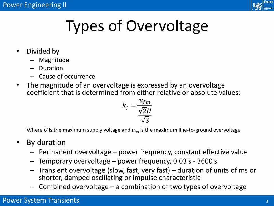
• Transient events caused by unstable electric arc create oscillations that are superposed on power frequency. Therefore, the resulting current reaches zero value already in times 1-4 (see figure).
• If the transient recovery voltage between the switch contacts rises faster than the dielectric strength of the space between both contacts, the circuit reconnects and needs to be switched off again.
Power System Transients 10
Power Engineering II
Switching off of Small Inductive Currents
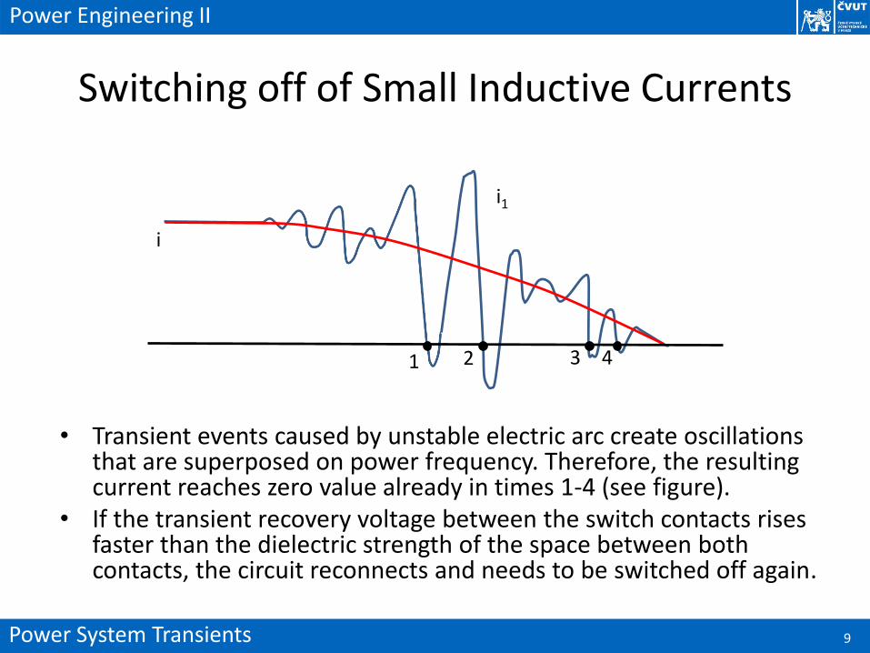
• The voltage between both contacts rises (drops) sharply whilst the distance between switch contacts increases insufficiently. This causes re-ignition of the arc after the first switch operation.
• Repetitive re-ignition creates saw tooth voltage on the transformer side (uT) of the circuit, as seen in the figure.
i
uT
t
t
Power System Transients 11
Power Engineering II
Switching of Capacitive Currents
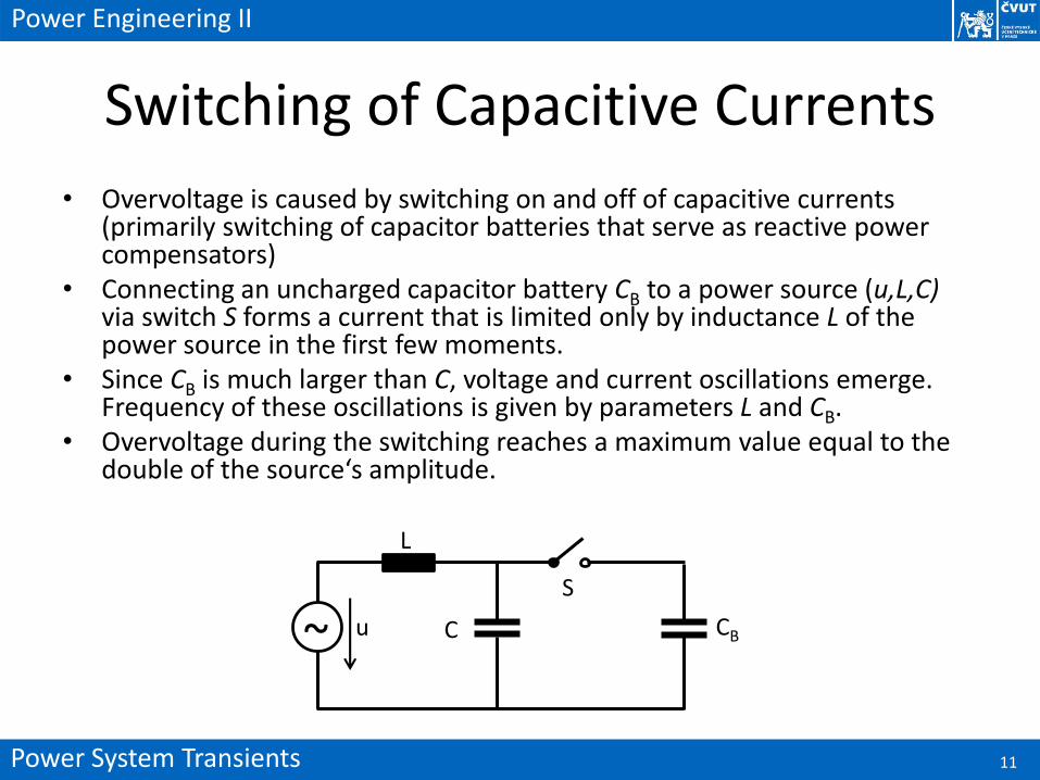
• Overvoltage is caused by switching on and off of capacitive currents (primarily switching of capacitor batteries that serve as reactive power compensators)
• Connecting an uncharged capacitor battery CB to a power source (u,L,C)via switch S forms a current that is limited only by inductance L of the power source in the first few moments.
• Since CB is much larger than C, voltage and current oscillations emerge. Frequency of these oscillations is given by parameters L and CB.
• Overvoltage during the switching reaches a maximum value equal to the double of the source‘s amplitude.
~ u
L
C CB
S

Power System Transients 12
Power Engineering II
Switching off of Capacitive Currents• With S switched on, the voltage on CB is higher than on the power source.• When the switch is disconnected, the current ceases to flow when it passes zero
value. Subsequently, a voltage difference emerges between the switch contacts.• The voltage of the source part of the circuit drops down to the network voltage via
a transient event. The voltage of the battery part of the circuit remains constant.• The voltage difference between contacts increases and an electric arc ignites at
time 2. Voltage on CB changes to uC via a transient. The maximum overvoltage during the event is equal to the triple of uC
t
t
i
uc
us
1 2

Power System Transients 13
Power Engineering II
Travelling Waves
Ldx Rdx
GdxCdx
dx
u(x,t) u(x+dx,t)
i(x+dx,t)i(x,t)
Circuit equations:
−𝑢 𝑥, 𝑡 + 𝑅𝑑𝑥𝑖 𝑥 + 𝑑𝑥, 𝑡 + 𝐿𝑑𝑥𝜕𝑖 𝑥 + 𝑑𝑥, 𝑡
𝜕𝑡+ 𝑢 𝑥 + 𝑑𝑥, 𝑡 = 0
𝑖 𝑥, 𝑡 − 𝐺𝑑𝑥𝑢 𝑥, 𝑡 − 𝐶𝑑𝑥𝜕𝑢 𝑥, 𝑡
𝜕𝑡− 𝑖 𝑥 + 𝑑𝑥, 𝑡 = 0
𝑢 𝑥 + 𝑑𝑥, 𝑡 − 𝑢(𝑥, 𝑡)
𝑑𝑥= −𝑅𝑖(𝑥 + 𝑑𝑥, 𝑡) − 𝐿
𝜕𝑖
𝜕𝑡
𝑖 𝑥 + 𝑑𝑥, 𝑡 − 𝑖(𝑥, 𝑡)
𝑑𝑥= −𝐺𝑢(𝑥, 𝑡) − 𝐶
𝜕𝑢(𝑥, 𝑡)
𝜕𝑡
𝜕𝑢
𝜕𝑥= −𝑅𝑖 − 𝐿
𝜕𝑖
𝜕𝑡
𝜕𝑖
𝜕𝑥= −𝐺𝑢 − 𝐶
𝜕𝑢
𝜕𝑡
Power System Transients 14
Power Engineering II
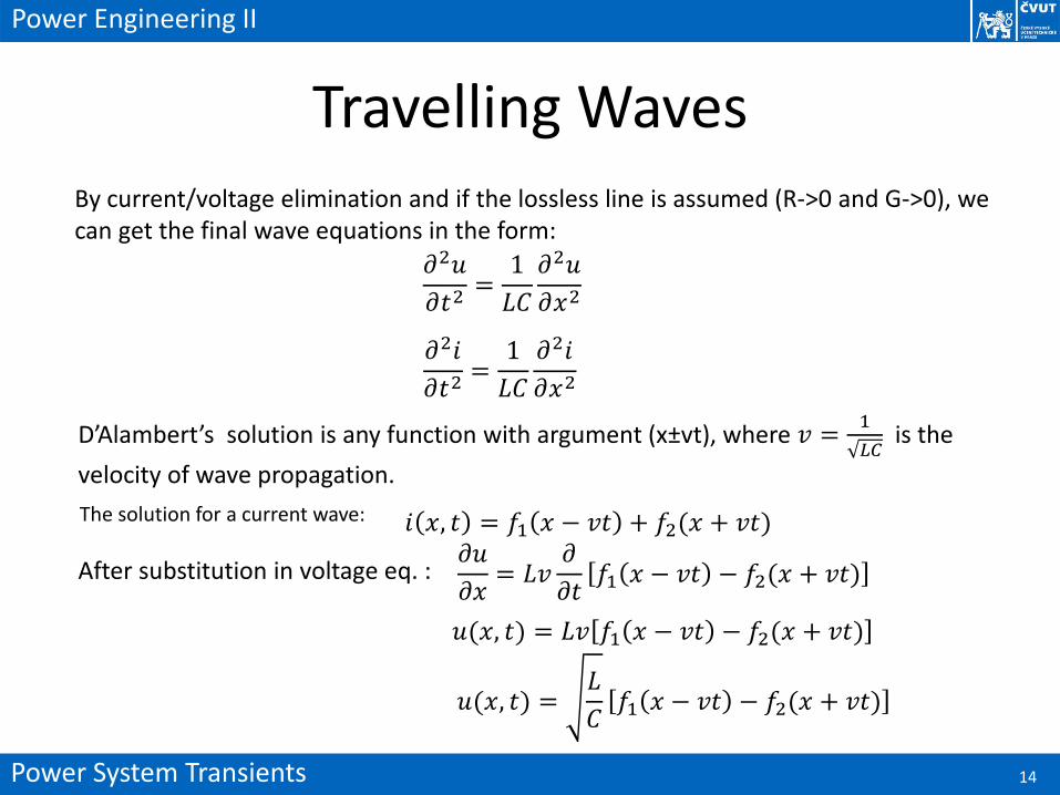
Travelling WavesBy current/voltage elimination and if the lossless line is assumed (R->0 and G->0), we can get the final wave equations in the form:
𝑖 𝑥, 𝑡 = 𝑓1 𝑥 − 𝑣𝑡 + 𝑓2(𝑥 + 𝑣𝑡)
𝜕2𝑢
𝜕𝑡2=
1
𝐿𝐶
𝜕2𝑢
𝜕𝑥2
𝜕2𝑖
𝜕𝑡2=
1
𝐿𝐶
𝜕2𝑖
𝜕𝑥2
D’Alambert’s solution is any function with argument (x±vt), where 𝑣 =1
𝐿𝐶is the
velocity of wave propagation.
The solution for a current wave:
After substitution in voltage eq. :𝜕𝑢
𝜕𝑥= 𝐿𝑣
𝜕
𝜕𝑡𝑓1 𝑥 − 𝑣𝑡 − 𝑓2(𝑥 + 𝑣𝑡)
𝑢(𝑥, 𝑡) = 𝐿𝑣 𝑓1 𝑥 − 𝑣𝑡 − 𝑓2(𝑥 + 𝑣𝑡)
𝑢(𝑥, 𝑡) =𝐿
𝐶𝑓1 𝑥 − 𝑣𝑡 − 𝑓2(𝑥 + 𝑣𝑡)

Power System Transients 15
Power Engineering II
Travelling Wavesv
u
i
u
i
v
u
i
v v
The voltage backward wave is in phase with the forward wave, the current backward wave is in opposite phase to the forward wave.
u
i
Power System Transients 16
Power Engineering II
Boundary influence to travelling waves
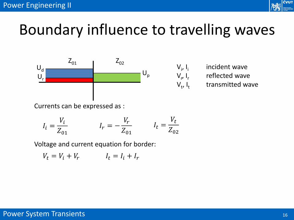
Vi, Ii incident waveVr, Ir reflected wave Vt, It transmitted wave
Z01 Z02Ud
UrUp
Currents can be expressed as :
𝐼𝑖 =𝑉𝑖𝑍01
𝐼𝑟 = −𝑉𝑟𝑍01
𝐼𝑡 =𝑉𝑡𝑍02
Voltage and current equation for border:
𝑉𝑡 = 𝑉𝑖 + 𝑉𝑟 𝐼𝑡 = 𝐼𝑖 + 𝐼𝑟

Power System Transients 17
Power Engineering II
Boundary influence to travelling waves
Voltage reflection coefficient 𝜌𝑉 =𝑉𝑟
𝑉𝑖:
𝑉𝑖𝑍01
−𝑉𝑟𝑍01
=𝑉𝑖𝑍02
+𝑉𝑟𝑍02
𝑉𝑟𝑉𝑖=
𝑍02 − 𝑍01𝑍01𝑍02
𝑍01 + 𝑍02𝑍01𝑍02
=𝑍02 − 𝑍01𝑍01 + 𝑍02
Similarly we can get current reflection coefficient:
𝜌𝐼 =𝑍01 − 𝑍02𝑍01 + 𝑍02
and voltage and current transmission coefficients:
𝜏𝑉 =2𝑍02
𝑍01 + 𝑍02𝜏𝐼 =
2𝑍01𝑍01 + 𝑍02

Power System Transients 18
Power Engineering II
Effect of line terminationsShort-circuit line:
Z0
V
V=0
V
I
v
v
vvV
Iv
vV
I
x
Z0
V
I
v
V
I
V
I
x
Open-circuit line:
v
v
v
v
v
I=0
V

Power System Transients 19
Power Engineering II
Effects of line terminationsLine termination in inductance:
Z0
V
V
Z0
Line termination in capacitance:
t
V
t
L C
V

Power System Transients 20
Power Engineering II
Lightning discharge
• Causes the overvoltage in electric power systems• The lightning discharge originates in lightning
clouds (cumulonimbus), which are consequences of intensive vertical air flow
http://www.jacksonsweather.com

Power System Transients 21
Power Engineering II
Charge distribution in clouds• Charge separation occurs inside a cloud – many theories of charge separation
mechanism exists, the whole process is still not fully understood• The upper part of a cloud consists of ice crystals with positive charge while the
lower part of a cloud consists of negatively charged water droplets• Negative charge in the lower part of clouds and positive charge in its upper part or
induced positive charge on the ground can be neutralized by lightning discharge, so we can recognize: – Lightning discharge between centers of negative and positive cahrge inside the clouds– Lightning discharge between clouds and Earth’s surface
++++
-- - -
+
+
+
-
-
- - -
+
-
+ + + + + ++
+
--- - - -
+
--
Power System Transients 22
Power Engineering II
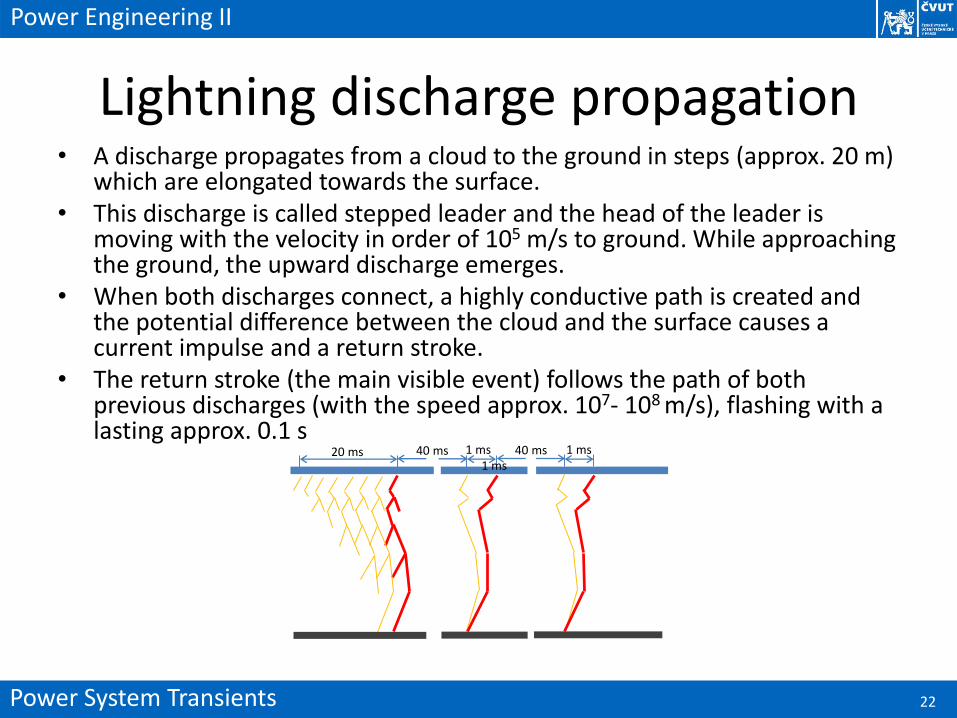
Lightning discharge propagation• A discharge propagates from a cloud to the ground in steps (approx. 20 m)
which are elongated towards the surface.• This discharge is called stepped leader and the head of the leader is
moving with the velocity in order of 105 m/s to ground. While approaching the ground, the upward discharge emerges.
• When both discharges connect, a highly conductive path is created and the potential difference between the cloud and the surface causes a current impulse and a return stroke.
• The return stroke (the main visible event) follows the path of both previous discharges (with the speed approx. 107- 108 m/s), flashing with a lasting approx. 0.1 s
20 ms 40 ms 1 ms 40 ms 1 ms1 ms

Power System Transients 23
Power Engineering II
Current of Lightning Discharge• Lightning current waveform is important for an assessment of
lightning effects to electric power systems• The parameters of current waveforms are statistical values
determined on the base of observations• Negative first partial discharge has higher amplitude than
subsequent partial discharges• Positive lightning has higher amplitude and lower steepness• Total time of lightning duration is usually hundreds of milliseconds
Peaks of currents (kA) Cumulative frequency
95% 50% 5%
Negative first partial discharge 14 30 80
Negative subsequent partial discharge
4,6 12 30
Positive lightning 4,6 35 250
Power System Transients 24
Power Engineering II
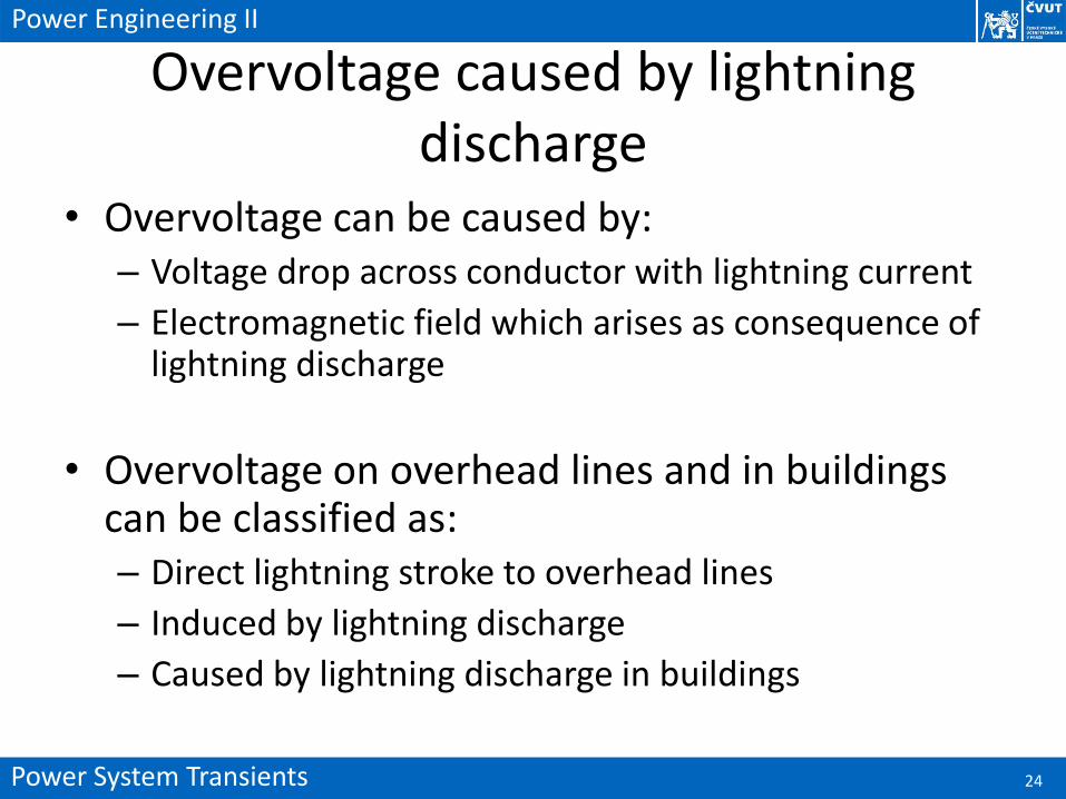
Overvoltage caused by lightning discharge
• Overvoltage can be caused by:– Voltage drop across conductor with lightning current
– Electromagnetic field which arises as consequence of lightning discharge
• Overvoltage on overhead lines and in buildings can be classified as:– Direct lightning stroke to overhead lines
– Induced by lightning discharge
– Caused by lightning discharge in buildings

Power System Transients 25
Power Engineering II
Direct stroke to overhead line• Injected current impulse propagates to both sides of
overhead line -> current and voltage travelling waves• Voltage and current waves are reflected in locations
where the change of surge impedance is present• If the over head line ground wire is struck, the
reflections occurs in the place of joints with towers and in the place of grounding of towers
• The most dangerous overvoltage arises at direct stroke of lightning to phase conductor of line; assuming the peak current of lightning discharge Im = 30 kA and line surge impedance Zv=300 Ω, then the peak value of overvoltage is:
𝑉𝑚 =𝑍𝑉2𝐼𝑚 =
300
230. 103 = 4,5 𝑀𝑉

Power System Transients 26
Power Engineering II
Overvoltage induced to line• Lightning stroke causes rapid change of
electromagnetic field and creates induced voltages
• Dangerous overvoltage for an insulation system can arise if the lightning strikes somewhere in the distance of up to 5 km from an overhead line
Z0VCm
Z02Z01
i/2 i/2
Z0V
Z02Z01
+
Capacitive coupling Inductive coupling
-E
Lm


![[Allan Greenwood] Electrical Transients in Power Systems (1991)](https://static.fdocuments.in/doc/165x107/5880e5541a28ab0d358b57fd/allan-greenwood-electrical-transients-in-power-systems-1991.jpg)