Power-system protection device with IoT-based support for ...
22
RESEARCH ARTICLE Power-system protection device with IoT- based support for integration in smart environments Octavian Mihai Machidon ID 1 *, Cornel Stanca 1 , Petre Ogrutan ID 1 , Carmen Gerigan 1 , Lia Aciu 2 1 Electronics and Computers, Transilvania University of Brasov, Brasov, Romania, 2 Electrical Engineering and Applied Physics, Transilvania University of Brasov, Brasov, Romania * [email protected] Abstract This paper proposes a power-system protection device designed to be integrated in smart environments based on Internet-of-Things technologies. The proposed system enhances electrical safety by fast disconnection of the power supply in case of fault events like leakage current, electrical arc, overcurrent or overvoltage and has been designed with the goal to be integrated in smart environments like smart homes or smart cities for protecting the electrical equipment. The system also enables real-time monitoring and notification events through an advanced communication interface using a data concentrator architecture. This paper provides an extended description of the proposed system’s design and implementa- tion, as well as the experimental validation results. Introduction The security and reliability of the electrical energy infrastructure is of vital importance today more than ever, given the degree to which electric-powered technology has become embedded in all human activities. Protecting the electrical power supply system against interruptions due to various faults is thus a main research concern [1]. One of the components involved in power-system protection is the circuit breaker, which is responsible for closing the system when a fault or anomaly occurs in order to protect the electrical equipment [2]. In today’s world, the technological trend of implementing “smart” technologies, fostered by the emergence of Cloud Computing and the Internet of Things (IoT), led to a transfiguration of ordinary devices and environments to “smart” entities [3]. In this context, traditional elec- trical protection devices also tend to transcend and become “smart” [4], and consequently offer improved fault-detection and protection, remote monitoring and event notification [5]. By becoming smart, a home is embedded with ubiquitous computing equipment that con- nects all the household devices to one another and the Internet. A smart city also embeds in the urban landscape computers, sensors, cameras and other sensitive equipment operating in the background. In these circumstances, protecting the power supply grid against faults PLOS ONE | https://doi.org/10.1371/journal.pone.0208168 December 5, 2018 1 / 22 a1111111111 a1111111111 a1111111111 a1111111111 a1111111111 OPEN ACCESS Citation: Machidon OM, Stanca C, Ogrutan P, Gerigan C, Aciu L (2018) Power-system protection device with IoT-based support for integration in smart environments. PLoS ONE 13(12): e0208168. https://doi.org/10.1371/journal.pone.0208168 Editor: Senentxu Lanceros-Mendez, Basque Center for Materials, Applications and Nanostructures, PORTUGAL Received: August 20, 2018 Accepted: November 13, 2018 Published: December 5, 2018 Copyright: © 2018 Machidon et al. This is an open access article distributed under the terms of the Creative Commons Attribution License, which permits unrestricted use, distribution, and reproduction in any medium, provided the original author and source are credited. Data Availability Statement: All relevant data are within the manuscript and its Supporting Information files. Funding: This work was supported by a grant of the Romanian National Authority for Scientific Research and Innovation, CNCS/CCCDI – UEFISCDI, project number PN-III-P2-2.1-PED- 2016-0570, within PNCDI III to PO. We hereby acknowledge the structural founds project PRO-DD (POS-CCE, 0.2.2.1., ID 123, SMIS 2637, ctr. No.
Transcript of Power-system protection device with IoT-based support for ...

RESEARCH ARTICLE
Power-system protection device with IoT-
based support for integration in smart
environments
Octavian Mihai MachidonID1*, Cornel Stanca1, Petre OgrutanID
1, Carmen Gerigan1,
Lia Aciu2
1 Electronics and Computers, Transilvania University of Brasov, Brasov, Romania, 2 Electrical Engineering
and Applied Physics, Transilvania University of Brasov, Brasov, Romania
Abstract
This paper proposes a power-system protection device designed to be integrated in smart
environments based on Internet-of-Things technologies. The proposed system enhances
electrical safety by fast disconnection of the power supply in case of fault events like leakage
current, electrical arc, overcurrent or overvoltage and has been designed with the goal
to be integrated in smart environments like smart homes or smart cities for protecting the
electrical equipment. The system also enables real-time monitoring and notification events
through an advanced communication interface using a data concentrator architecture. This
paper provides an extended description of the proposed system’s design and implementa-
tion, as well as the experimental validation results.
Introduction
The security and reliability of the electrical energy infrastructure is of vital importance today
more than ever, given the degree to which electric-powered technology has become embedded
in all human activities. Protecting the electrical power supply system against interruptions
due to various faults is thus a main research concern [1]. One of the components involved in
power-system protection is the circuit breaker, which is responsible for closing the system
when a fault or anomaly occurs in order to protect the electrical equipment [2].
In today’s world, the technological trend of implementing “smart” technologies, fostered by
the emergence of Cloud Computing and the Internet of Things (IoT), led to a transfiguration
of ordinary devices and environments to “smart” entities [3]. In this context, traditional elec-
trical protection devices also tend to transcend and become “smart” [4], and consequently
offer improved fault-detection and protection, remote monitoring and event notification [5].
By becoming smart, a home is embedded with ubiquitous computing equipment that con-
nects all the household devices to one another and the Internet. A smart city also embeds in
the urban landscape computers, sensors, cameras and other sensitive equipment operating in
the background. In these circumstances, protecting the power supply grid against faults
PLOS ONE | https://doi.org/10.1371/journal.pone.0208168 December 5, 2018 1 / 22
a1111111111
a1111111111
a1111111111
a1111111111
a1111111111
OPEN ACCESS
Citation: Machidon OM, Stanca C, Ogrutan P,
Gerigan C, Aciu L (2018) Power-system protection
device with IoT-based support for integration in
smart environments. PLoS ONE 13(12): e0208168.
https://doi.org/10.1371/journal.pone.0208168
Editor: Senentxu Lanceros-Mendez, Basque Center
for Materials, Applications and Nanostructures,
PORTUGAL
Received: August 20, 2018
Accepted: November 13, 2018
Published: December 5, 2018
Copyright: © 2018 Machidon et al. This is an open
access article distributed under the terms of the
Creative Commons Attribution License, which
permits unrestricted use, distribution, and
reproduction in any medium, provided the original
author and source are credited.
Data Availability Statement: All relevant data are
within the manuscript and its Supporting
Information files.
Funding: This work was supported by a grant of
the Romanian National Authority for Scientific
Research and Innovation, CNCS/CCCDI –
UEFISCDI, project number PN-III-P2-2.1-PED-
2016-0570, within PNCDI III to PO. We hereby
acknowledge the structural founds project PRO-DD
(POS-CCE, 0.2.2.1., ID 123, SMIS 2637, ctr. No.

becomes even more important, given the increasing number of sensitive devices connected in
the emerging Smart world.
Moreover, the traditional electrical protection for residential, office and industrial buildings
is based on classic circuit breakers tripping or fuses being blown when an overload happens,
thus offering limited protection and warning [6].
This paper describes the design, implementation and experimental validation of the ELSA
(ELectrical SAfety) power-system protection device with built-in support for IoT-based inte-
gration in smart environments like a Smart City or a Smart Home. The main features of the
proposed system are:
• Advanced fault-detection and protection through high-speed disconnection in the case of:
overcurrent, overvoltage, leakage current and electric arc;
• Real-time monitoring by sending recorded events to a Web server where the information is
accessible through an online Web-based interface;
• Real-time notifications by e-mail and text messages to designated persons;
• Flexible and scalable communication infrastructure supporting easy integration in smart
environments and with other utility service operators through Web-based protocols, services
and APIs;
The rest of the paper is organized as follows: section II provides background and related
work on this topic, section III describes the system architecture detailing the three components
(hardware, software and communication network and data concentrator), section IV presents
the experimental validation of the system while section V draws conclusions and underlines
future research directions.
Background and related work
Relevant literature in this domain underlines three key features for such power system protec-
tion devices: disconnection speed, reliability and cost [7].
The current state-of-the-art in this field highlights that the traditional circuit breakers are
still widely used today for power-system protection, these devices being usually designed to
protect against a single power supply grid fault event. A new generation of circuit breakers
has been developed by Eaton in 2016: Arc Fault Detection Device (AFDD) which provides
enhanced protection against electric arcs, leakage current, overcurrent and overvoltage [8].
One of the recent trends is linked to the emergence of micro-grids, which need to operate
safely in both islanded and grid-connected modes. Hence, the re-shaping of the traditional
power grid (transcending into Smart Grid and micro-grids) will require highly flexible distri-
bution management systems and a re-design of protection strategies [9]. The reliability of
micro-grids is an important research direction, given their sensitivity to power outages which
can increase the average frequency and duration of interruptions [10]. Thus, existing research
focuses on designing reliable protection solution for such systems [11] (e.g., the authors in [12]
provide a comparison between protection solutions for AC and DC micro-grids, highlighting
the advantages in the case of DC protection).
The DC micro grid systems are present in an increasing number of applications lately due
to their important assets. Thus, protecting DC micro grids and the connected consumers to
such grids is an important research subject, addressed by several recent papers. As such, in
[13] the authors analyze the multi-terminal protection in DC grids for aerospace applications.
In [14] a pilot project for electric vehicle charging stations fed by renewable: PV and train
regenerative braking is presented, with details regarding control and protection features. An
Power-system smart protection device with IoT-based support
PLOS ONE | https://doi.org/10.1371/journal.pone.0208168 December 5, 2018 2 / 22
11/2009) for providing the infrastructure used in
this work.
Competing interests: The authors have declared
that no competing interests exist.
advanced protection method against voltage anomalies in DC grids is described in [15], where
the protection circuit located in the energy converter ensures a fast decoupling and fault iden-
tification in a multi-terminal grid. A similar protection system intended for a multi-terminal
DC compact node feeding electric vehicles on electric railway systems, secondary distribution
networks, and PV systems is also presented in [16].
Another sensitive issue with regard to power system fault-protection is related to the com-
plexity of integrating renewable energy sources in the existing power grid, which underlines
even more the necessity of viable solutions against faults like short-circuits, electric arcs, and
increased harmonics [17]. Consequently, this highlights the importance of disconnecting
power when detecting current zero-crossing. Nevertheless, the assimilation of distributed
sources in to existing power distribution networks raises important technical challenges,
including issues related to the need of enhanced protection systems against power failures
[18].
In this context, the emerging research trend in this field envisages designing and imple-
menting innovative protection solutions, like the one described in a recent patent application
[19], which proposes a similar device for ensuring electrical load disconnection when detecting
various faults in the power supply grid.
The analysis of the current state-of-the-art shows that there are very few smart circuit
breaker—type solutions, and the traditional protection systems do not offer real-time monitor-
ing and communication features for fast IoT-based integration in smart environments. There
is an emerging Electrical Substation Communications Standard (IEC-61850) [20] that is Smart
Grid compatible and enables communication over the power grid for monitoring and control,
however such systems are generally dedicated for power utility providers and specialists, not
being designed to provide monitoring or notifications to end-users or third-parties (e.g local
public administration entities or emergency services).
Related research papers describing smart circuit breakers (circuit breakers that are remotely
controllable and monitored) include smart breakers used for local power generator capacity
optimization [21], aircraft electrical power distribution protection [22] and also applications
in micro-grids for enhanced grid protection [23] and also optimal load scheduling [24]. A
similar but less complex system with the one described by this paper is presented in [25],
and it represents a remotely controllable circuit breaker protecting against short-circuits and
overloads.
Most of the above-mentioned examples of smart circuit breakers offer the traditional
protection features of a classic breaker but in addition provide remote control for coupling/
decoupling and monitoring. A recent study [26] analyzed the security implications of having
remotely controlled circuit breakers and underlined the necessity of a secure communication
channel to avoid possible attacks.
The ELSA power-system protection device described in this paper has been designed with
the goal to be integrated in smart environments like smart homes or smart cities for protecting
the electrical equipment from faults and anomalies. It not only allows remote monitoring and
control of the coupling/decoupling feature, but also supports real-time notifications and pro-
vides enhanced protection against a wide range of electrical failures.
The concept of smart buildings, smart homes or home automation has been developed with
the goal to make the living environment safer, more convenient and more accessible for the
inhabitants [27]. The features that a smart home offers include, among other, environment
monitoring [28], building security [29] or remote medical monitoring [30]. Given that a smart
home integrates a complex network of devices, sensors and computers, and since this concept
also aims at improving living safety, one of the key issues that need to be addressed is related
to the monitoring and protection of the power system. In other words, if the equipment inside
Power-system smart protection device with IoT-based support
PLOS ONE | https://doi.org/10.1371/journal.pone.0208168 December 5, 2018 3 / 22

the home became smart, it is natural to expect that the circuit breaker system should transcend
into an intelligent, enhanced protection system.
Given the position of the circuit breaker in a smart building, adjacent to the power meter,
we envision our protection system to integrate in the Smart Grid—Smart Home synergy as a
system offering active protection but in the same time providing real-time monitoring of the
link between the two infrastructures, fostering the secure interaction between the two entities
[31].
With regard to the second application domain targeted for our device, smart cities, this was
identified based on the collaboration between Transilvania University of Brasov and the local
Brasov authorities in the framework of the Brasov Smart City roadmap. Brasov is one of the
Central and East-European cities with a strategy for implementing smart ICT-based technolo-
gies like intelligent public lighting [32], GIS (Geographical Information System) and video-
enabled traffic surveillance for real-time analysis and optimization or WoT (Web of Things)-
enabled services like open Smart City Data (e.g. precipitation measurements) [33].
The intelligent public lighting network integrates a remote lighting management system
able to monitor all the lights in the city remotely, using a Web-based interface. Also, this sys-
tem has included the implementation of environmental sensors, video cameras, panic buttons
and a municipality-wide Wi-Fi MESH network, all being monitored and managed using the
same interface that allows analysis and planning instruments for reducing energy consump-
tion and maintenance costs [34].
In this context, an important issue regards fault identification and equipment protection,
which can be addressed properly with the proposed system. Thus, the optical elements of the
lighting devices, but also the other equipment connected to this intelligent network (cameras,
microphones, alarm systems, sensors) can be protected against a wide range of power system
faults which are identified and signaled in real-time.
The public lighting poles part of the IoT-based intelligent lighting system integrate only a
basic circuit breaker offering decoupling in the case of a short circuit. Thus, the ELSA device
provides additional protection against a wider range of electrical faults. This is also the case of
residential or industrial buildings, most of which are protected only against short-circuit (and
only some having differential breakers). In both cases, deploying the ELSA device enables,
besides enhanced protection, real time notification of the public energy provider or the build-
ing owner about the fault events as they occur.
Materials and methods
Hardware implementation
General description. The ELSA protection device described in this paper (and illustrated
in Fig 1) has been implemented based on an original, innovative design, and ensures the pro-
tection of electrical consumers connected to the public power supply grid by disconnecting the
electrical supply in the event of several faults: overvoltage, overcurrent, leakage current and
electrical arc. In the left subfigure the ELSA device is displayed in its case, with the modules
being identified as follows:
1. Power supply (230V AC to 12V DC)
2. Control module containing three stacked PCBs (A, B, C from the right subfigure)
3. Relay (SW2) for neutral switching
4. Casing including the solid state relay (SW1)
Power-system smart protection device with IoT-based support
PLOS ONE | https://doi.org/10.1371/journal.pone.0208168 December 5, 2018 4 / 22

The right subfigure shows the microcontroller unit with its three overlayed PCBs:
(A) PCB for microntroller and switched supply sources
(B) PCB for sensors
(C) PCB for user control (via the buttons) and states display
The main features of the protection system are:
• All the protection sub-systems are integrated in a single device, mounted in a DIN Rail
enclosure to ensure flexibility in choosing the appropriate protection modules for each appli-
cation (As seen in Fig 1).
• Rapid fault detection—in under 250us.
• Fast electrical load decoupling (maximum 10ms) which takes place at the first current zero-
crossing following the fault event for overvoltage, leakage current and electrical arc
• Automatic re-coupling following overcurrent and overvoltage events, if the fault does not
persist
• Manual (after on-site inspection) re-coupling following leakage current and electric arc,
events considered serious and life-threatening since they may imply electrocution or fire.
• Local display for status messages and data transmission to a concentrator for real-time moni-
toring via Web-based interface
• Built-in self-test (BIST) for checking system’s integrity at power-on and periodically during
operation; local and remote notification of health status
• Protected against overvoltage of its own power supply
This device is thus designed not only as a replacement for the traditional circuit breakers,
but an extension that offers enhanced protection and real-time notification features. In some
cases, according to the deployment location’s specifics, due to the fact that the ELSA device is
equipped with an execution element that has a maximum admissible current of 1kA, a classic
short-circuit breaker with a larger short-circuit current (10kA) can be connected downstream
Fig 1. The power system protection device.
https://doi.org/10.1371/journal.pone.0208168.g001
Power-system smart protection device with IoT-based support
PLOS ONE | https://doi.org/10.1371/journal.pone.0208168 December 5, 2018 5 / 22

of the device. This classical downstream breaker has therefore a higher decoupling current
value than the ELSA breaker, which could increase the safety of the ELSA system in the case of
a short-circuit where the current exceeds 1kA.
The protection device is based on a PIC 16F1829 microcontroller and can operate either in
stand-alone mode, displaying its status on a local 7-segment display, or using a communica-
tion module to integrate it in an IoT network. The thresholds for load decoupling in case of
overcurrent, overvoltage, leakage current and electric arc are programmable, and can be
updated on-site by cable re-programming the microcontroller software (e.g. at user request).
For future developments we envisage implementing remote, online update of these thresholds.
This feature will be implemented with enhanced security (data encryption) to ensure the safety
of the system.
An overview of the protection device’s architecture is depicted in Fig 2. A list and a short
description for each of the internal modules is provided in Table 1.
Central microcontroller unit and voltage/current sensors. The Microchip PIC 16F1829
microcontroller’s resources, 1KB RAM, 14KB Flash and an internal 32MHz oscillator provide
appropriate performance for this application.
The GVC module receives the signal from the grid voltage sensor (GVS) following a low
pass filtering for removing disturbing frequencies.
The input signal for the LCC module is provided by the Hall sensor output signal which
underwent low pass filtering for removing the higher order harmonics.
In order for the EAD module to accurately detect the electric arc, a high pass filter selects
the specific higher order harmonics encountered in the case of an electric arc and an analogic
comparator compares the harmonics’ amplitude with a pre-defined threshold and activates the
digital input DI.
In the LKC module, an operational amplifier is being fed with the input signal coming from
a Hall sensor through which both phase and ground wires pass. The signal is proportional
with the difference of the two currents in the phase and ground wires. Both signals generated
by LCC module (proportional with the load current) and by the LKC module (proportional
with the current difference between phase and ground) are applied to the analog inputs of the
microcontroller.
Load decoupling circuit and power supply. For decoupling the load a static SSR module
SSP1A125BD Schneider Solid state relay is used, having a 3-32V DC input, 24-300 V AC out-
put, and 25A maximum current, and for neutral decoupling we have used a relay (RLY).
Decoupling takes place first for the phase and then for the neutral, while recoupling occurs in
the reverse order. The integrity of the SSR and the relay is being checked at device start-up and
periodically during operation.
The PS power supply is a switching MEAN WELL DR-15-12 supply with a 12V DC output,
1.25A rated current and 85-264V AC supply voltage. The power supply is protected against
overvoltage by the PSP (Power Supply Protection) circuit, consisting of a resistor connected
in parallel with a triac. Under normal conditions, when the grid voltage is below a maximum
value, the μC activates a triac in order to short-circuit the resistor connected in series with the
power supply. When the grid voltage exceed the maximum value, the μC deactivates the triac,
leading to the resistor being connect in series with the power supply, thus distributing the volt-
age between the resistor and the PS. When the grid voltage returns to nominal value, the μC
commands the re-activation of the triac.
Design and implementation precautions were taken in order to ensure that, among other
potential disturbing factors, the opening and reclosing of the circuit breaker does not affect the
operation of the microcontroller. Thus, the power supply has been specifically designed to pro-
vide a constant output voltage given any input voltage in the range 100-240V A.C. For voltages
Power-system smart protection device with IoT-based support
PLOS ONE | https://doi.org/10.1371/journal.pone.0208168 December 5, 2018 6 / 22

higher than 240V (up to 400V) the supply is provided with a protection that ensures a safe
operation within parameters for an undefined period of time. Also, the microcontroller sup-
ports an input voltage between 1.8 and 5.5 V D.C. and it has an efficient low pass filter placed
in the proximity of the supply pin.
Fig 2. Internal architecture of the protection device.
https://doi.org/10.1371/journal.pone.0208168.g002
Power-system smart protection device with IoT-based support
PLOS ONE | https://doi.org/10.1371/journal.pone.0208168 December 5, 2018 7 / 22

Moreover, during the functional testing with all event types and a wide variety of RLC
loads, the test stand continuously generated all types of fault events and measured the decou-
pling/recoupling timings. During these tests and sequences of coupling/decoupling the
breaker, the microcontroller operated unaffected by any disturbances.
Modular concept of the ELSA device. The WCM (Wireless Communication Module) is
connected to the microcontroller via SPI and can be of different types, according to the client’s
/ deployment location’s requirements. For the household deployment of ELSA, we envisaged a
3G WCM transmission module, in which case the communication with the data concentrator
for event signaling is performed using the mobile phone network. For the intelligent lighting
project under implementation with the local municipality, we used a LoRa (Long Range Wide-
area network) WCM module with a maximum transmission range of about 10km in order
to ensure integration with the existing LoRa-based network deployed throughout the city. In
the case of deploying the ELSA device in households located in large apartment buildings, we
envisaged as the most favorable solution an RF WCM module. Thus, the laboratory tests were
performed using RFM12B, a transceiver with FM modulation and a typical transmission range
of about 100m, meeting the field requirements in this deployment scenario, for sending data
from each ELSA device to a local concentrator in each apartment building. In this scenario,
securing the data was performed using 16-bit encryption, and the local concentrator sends the
data forward to the global concentrator via Ethernet. The ELSA device was also programmed
in order to periodically check the health status of the connection with the local concentrator
by sending a health-check message and waiting for the response—in case of a communication
failure this is signaled as an error code on the local display. Currently, we are looking (together
with the local municipality) into ensuring a higher grade of IoT-compatibility regarding the
communication part of ELSA according to the international standards promoted by the Wi-
SUN alliance (Wireless Interoperable Smart Utility Networks).
The ELSA protection device has a modular concept, i.e. can be used in various configura-
tions. The device can be configured using the basic modules that ensure either only phase or
both phase and neutral decoupling, to which a transmission module can be added. Several
configurations as identified by potential users were laboratory tested:
Table 1. Internal modules description.
Module
name
Description
μC PIC 16F1829 Microcontroller (where AI stands for Analog Input, DI –Digital Input, DO -Digital
Output, SPI –Serial Peripheral Interface)
PS Power Supply (this may be linear or switched)
PSP Power Supply overvoltage Protection circuit
GVS Grid Voltage Sensor
GVC Grid Voltage Conditioning circuit
LCS Load Current Hall Sensor
LCC Load Current signal Conditioning circuit
EAD Electric Arc Detection circuit
LKS Leakage current Hall Sensor
LKC Leakage current signal Conditioning Circuit
SSR Switch for line connected to the load (Solid State Relay)
RLY Switch for neutral connected to the load (Relay)
WCM Wireless Communication Module (connected to CPU via SPI)
UC User Control (A button for On (to connect the load) and Off (to disconnect the load), a button for
Enabling and Disabling the electric Arc protection and a 7-segment display)
https://doi.org/10.1371/journal.pone.0208168.t001
Power-system smart protection device with IoT-based support
PLOS ONE | https://doi.org/10.1371/journal.pone.0208168 December 5, 2018 8 / 22

• Basic protection device without communication module
• Basic protection device with just phase decoupling
• Protection device with Ethernet communication module (household use)
• Protection device with 3G communication module (household use)
• Protection device with LoRa communication module (for integration in the smart city
network)
• Portection device with RF module (for users living in apartment buildings)
Other communication modules can be accomodated by the device, e.g. WiFi or PLC
(Power Line Communications), but these configurations have not been tested yet.
Embedded software
Fig 3 illustrates the control flow diagram for the embedded software running on the PIC
16F1829 microcontroller.
The diagram shows the sequential measurements and checks for grid voltage, load current,
leakage current and the presence of an electric arc. In each of these measurement stages any
exceeding of the maximum threshold (previously programmed) will lead to the decoupling of
the electrical load. In the event of overcurrent or overvoltage, the system attempts to automati-
cally re-couple the load after a specific programmed interval has elapsed. In case the fault per-
sists, the load remains de-coupled; a maximum of three automatic re-coupling attempts are
performed.
Following a decoupling caused by an electric arc or leakage current, re-coupling can be
made only after a manual user confirmation (performed by pushing a button on the device—
in the User Control module) given the potential dangerous circumstances involved in the case
of such events.
While the diagram shown in Fig 3 displays a sequential flow of the operations, the practical
implementation of the software is based on the interrupt system of the microcontroller. Thus,
the interrupts are generated by both external (arc electric detection and front panel events)
and internal sources (microcontroller timers dedicated to the generation of pre-programmed
time intervals).
The detection of an electric arc generates an interruption that enables Timer 1 to determine
the duration of that electric arc. The event will cause the load to be decoupled if the persistence
determined is greater than a predefined threshold. Timer2 is used to generate the sample rate
(period of 250us). Each Timer2 interrupt triggers a routine that reads analog values of grid
voltage, load current and leakage current. If any of these values exceeds the limit, the load
decoupling is performed (both switches turn off). The healthy state of the switches is deter-
mined periodically following self-tests generated by interrupts triggered by Timer3.
Communication interface and data concentrator
The communication infrastructure fosters data transmission from each protection device
towards a Web server that centralizes it and provides an online Web-based interface for
remote monitoring and control.
This infrastructure has been designed and implemented using IoT-compatible technologies
and design paradigms, including optimized Internet protocols (based on HTTP requests) and
communication standards. The communication system represents an extended development
of a previous implementation described in [35].
Power-system smart protection device with IoT-based support
PLOS ONE | https://doi.org/10.1371/journal.pone.0208168 December 5, 2018 9 / 22

In the context of the modular concept of the ELSA protection device, several communica-
tion configurations have been tested. We have focused our efforts on two in particular: the RF
communication with local concentrator for deployment in apartment buildings (described
below) and the integration in the city’s smart network (using LoRa).
Fig 3. Embedded software control flow diagram.
https://doi.org/10.1371/journal.pone.0208168.g003
Power-system smart protection device with IoT-based support
PLOS ONE | https://doi.org/10.1371/journal.pone.0208168 December 5, 2018 10 / 22

The communication system for the household apartment-building scenario comprises
embedded networking (RF) capabilities in each protection device, a (local, in the field) data con-
centrator, a Web server (global concentrator) and a Web-based interface for monitoring and con-
trol of the entire system. Fig 4 displays an overview of the communication system’s architecture.
Each protection device embeds an RF module connected to the microcontroller that is used
to transmit the status and events detected to the local concentrator, which is also a microcon-
troller device integrating an RF module and Ethernet shields. The local concentrator receives
RF broadcasts from the protection devices in range, confirms the receive by sending back an
acknowledgement, processes their input, wraps it up in JSON format and sends it as a HTTP
request to an URL representing an API (Application Programming Interface) point of the
global concentrator (which is actually a Web server). In order to enhance the reliability of the
system, the local concentrator periodically sends “status check” messages to each of the protec-
tion devices in its range and expects a health status report in order to verify their functionality
from time to time.
Thus, the communication infrastructure based on a local concentrator is very similar to the
one used in advanced metering infrastructures (AMI), where a local concentrator is also used
for collecting electricity usage data from residential electricity meters [36], using Wi-Fi or PLC
(power line communication technologies) [37].
The global concentrator, a node.js Web Server implemented and deployed on a Linux
machine in our department (running the http://etc.unitbv.ro domain), provides an API used
for communicating with the local concentrator devices by HTTP GET-POST requests encap-
sulating data as JSON strings in the requests’ body. Data storage and management is accom-
plished using a PostgreSQL database interfaced using specific node.js modules. In addition to
adding each event to the map, an e-mail and SMS message (Short Message Service) are being
sent to designated contacts for real-time notification.
Data communication between the local concentrators and the Web server for transmitting
information received from the protection devices has been implemented based on GET or
POST requests made from the local concentrators to the URL http://etc.unitbv.ro/elsa/api/v1/
reports with the data encapsulated in the request’s body as a JSON string.
The Web-based interface (Fig 5) has been implemented using JQuery, Bootstrap, CSS and
HTML and displays information about the operational protection devices (the recorded events
in the database and their current status). This approach is a renowned practice in this field in
Fig 4. Overview of the communication system architecture.
https://doi.org/10.1371/journal.pone.0208168.g004
Power-system smart protection device with IoT-based support
PLOS ONE | https://doi.org/10.1371/journal.pone.0208168 December 5, 2018 11 / 22

order to make interaction with the protection devices easier by using a Web application (like
the WebIoT app [38]). The Web page is easily scalable according to the displaying device spe-
cifics, with enhanced support for Mobile browsers included. The interface is accessible on a
public URL (http://etc.unitbv.ro/elsa), access being regulated based on user authentication and
privileges.
The Web interface provides both a table view (as shown in Fig 6) and a geo-referenced visu-
alization of the protection devices and recorded events using the Google Maps JavaScript API.
A Google Map is instantiated and populated with markers corresponding to each recorded
event from the database. A mapping has been made to associate each event type a different
marker color for better visualization. Extensive details about each event are displayed when the
corresponding marker is clicked on the map.
In designing the protection device we have envisaged integrating the concepts and para-
digms of the Internet of Things [39] in order to provide advanced, remote monitoring of the
events and real-time notifications. Such an approach fostering the synergy between the arising
IoT and traditional electrical protection system has the benefits of providing improved scal-
ability, security and interoperability of the entire system, and pertains to a newly emerging
concept of the Internet of Energy (IoE) [40], thus meeting the requirements necessary for inte-
grating our protection system in Smart City IoT-based infrastructure in Brasov.
To summarize, our approach for transcending a traditional electrical protection system to
one that is “IoT-ready” brings the following important features:
• Easy and uniform interaction with other communication and data systems due to the effec-
tiveness of IP-based networking [41].
• Low-power overall consumption by integrating low-power microcontrollers and communi-
cation shields. (Thus enforcing the current trends in IoT communication devices [42]).
• Simplified communication architecture based on HTTP requests, consequently reducing the
complexity of the hardware/software implementation.
• Interoperability—achieved by using IP based communication, HTTP requests and JSON-
structured messages—that allows a seamless integration with other systems.
• Scalability—the architecture of the entire communication system allows connecting a vari-
able number of devices “on the fly”.
• Easy data exchange with other entities (e.g. utility companies, emergency services).
Fig 5. Web interface for remote monitoring of the protection devices—Homepage view.
https://doi.org/10.1371/journal.pone.0208168.g005
Power-system smart protection device with IoT-based support
PLOS ONE | https://doi.org/10.1371/journal.pone.0208168 December 5, 2018 12 / 22

Fig 6. Screenshot from a mobile device showing the recorded events by the devices in a table format.
https://doi.org/10.1371/journal.pone.0208168.g006
Power-system smart protection device with IoT-based support
PLOS ONE | https://doi.org/10.1371/journal.pone.0208168 December 5, 2018 13 / 22

Results and discussion
Load decoupling and recoupling simulations
Simulink simulations were performed prior to device implementation, as shown by Fig 7.
These simulations implied the development of a simulation model of the execution element
(triac and associated components) and the study of the waveforms during connection/discon-
nection for different combinations of R, L and C. The simulation also considered slow start
recoupling by commanding a variable triac firing angle. According to the simulation, the cur-
rents’ waveform for some loads was altered to such an extent, therefore these load scenarios
have not been implemented in practice.
Functionality and reliability testing in laboratory
The ELSA protection device underwent functional testing with R, L, and C loads in different
combinations, measuring the decoupling speed for various faults and also validating the data
Fig 7. Simulation showing load coupling with variable triac firing angle. Voltage (up) and current (down) load
variations for a RLC load.
https://doi.org/10.1371/journal.pone.0208168.g007
Power-system smart protection device with IoT-based support
PLOS ONE | https://doi.org/10.1371/journal.pone.0208168 December 5, 2018 14 / 22

communication infrastructure. In order to accurately determine the reliability of the device, a
dedicated test stand has been designed and developed that continuously generates all types of
fault events and measures the decoupling/recoupling timings. This stand also supports acceler-
ated reliability testing, including temperature and humidity variation, according to standard
EN 62059-31-1.
Fig 8 shows the waveforms corresponding to load voltage and current during a coupling
followed by a decoupling. In this figure, the load voltage is represented by the blue sinusoidal
signal, and the load current by the red sinusoidal signal for an R load for a scenario in which
a 20% higher overload than the admissible threshold is detected. In this case, event detection
and decoupling timings are similar to those of a traditional circuit breaker. The waveforms in
the case of decoupling and recoupling are shown for the event of overload detection, but are
similar for any other fault event (electric arc, leakage current or overvoltage), only the decou-
pling time interval varies.
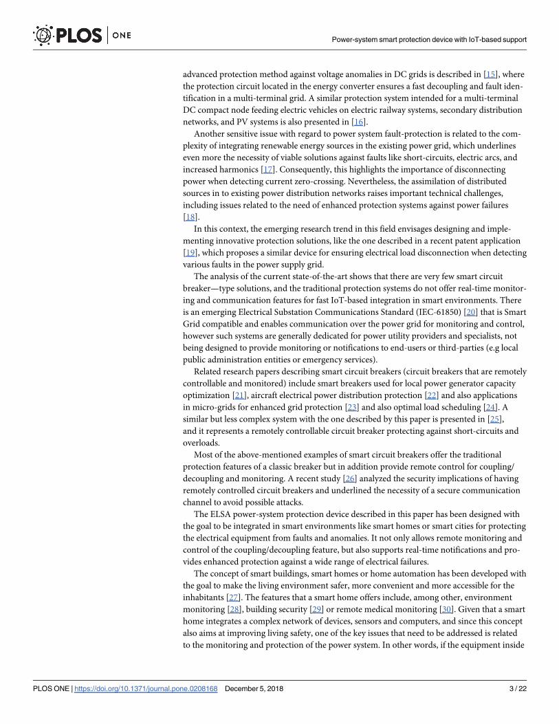
Fig 9 depicts a coupling with a duration of 1 semi-period for a RL load and the sudden volt-
age variation at decoupling, during the current’s zero crossing. The waveforms correspond to
an overload event with a 50% higher load than the admissible threshold.
The figure also shows that both load coupling and load decoupling are performed by the
device at the current’s zero crossing, which ensures minimum perturbations being generated
in the electrical grid. The analysis of current samples and detecting the faulty event takes one
period of the grid’s voltage.
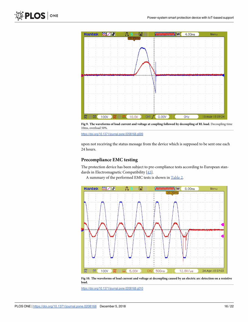
A decoupling event caused by an electric arc detection is depicted in Fig 10, where the cur-
rent variations caused by the electric arc are visible.
An analysis was also performed in order to proper handle various failure scenarios caused
by malfunctions of the ELSA device. In the case of decoupling/recoupling faults a specific
error message is shown on the local display together with an error notification message sent to
the user via SMS. If the malfunction involves critical system components (e.g. the microcon-
troller or power supply), the device still offers basic protection against short-circuit until the
defects have been remedied. In this case, remote fault detection is performed by the server
Fig 8. The waveforms of load current and voltage at coupling an additional R load causing the decoupling in 10
periods—200ms (in the event of a 20% overload).
https://doi.org/10.1371/journal.pone.0208168.g008
Power-system smart protection device with IoT-based support
PLOS ONE | https://doi.org/10.1371/journal.pone.0208168 December 5, 2018 15 / 22
upon not receiving the status message from the device which is supposed to be sent one each
24 hours.
Precompliance EMC testing
The protection device has been subject to pre-compliance tests according to European stan-
dards in Electromagnetic Compatibility [43].
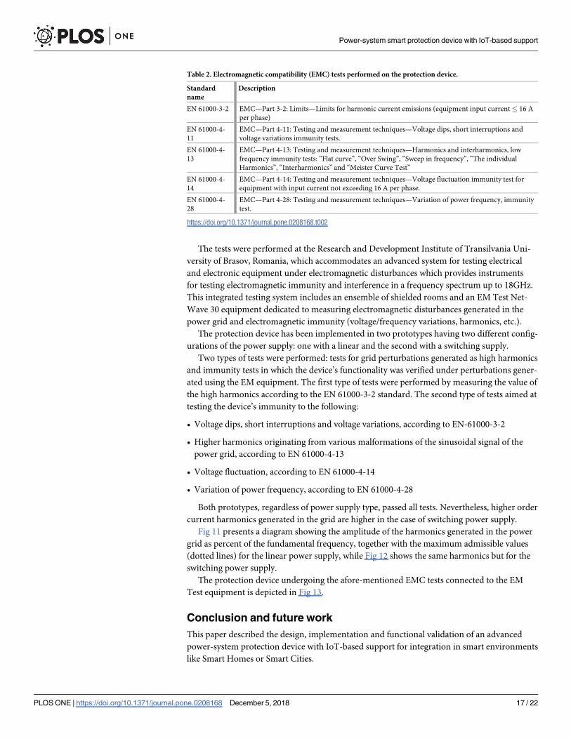
A summary of the performed EMC tests is shown in Table 2.
Fig 9. The waveforms of load current and voltage at coupling followed by decoupling of RL load. Decoupling time
10ms, overload 50%.
https://doi.org/10.1371/journal.pone.0208168.g009
Fig 10. The waveforms of load current and voltage at decoupling caused by an electric arc detection on a resistive
load.
https://doi.org/10.1371/journal.pone.0208168.g010
Power-system smart protection device with IoT-based support
PLOS ONE | https://doi.org/10.1371/journal.pone.0208168 December 5, 2018 16 / 22
The tests were performed at the Research and Development Institute of Transilvania Uni-
versity of Brasov, Romania, which accommodates an advanced system for testing electrical
and electronic equipment under electromagnetic disturbances which provides instruments
for testing electromagnetic immunity and interference in a frequency spectrum up to 18GHz.
This integrated testing system includes an ensemble of shielded rooms and an EM Test Net-
Wave 30 equipment dedicated to measuring electromagnetic disturbances generated in the
power grid and electromagnetic immunity (voltage/frequency variations, harmonics, etc.).
The protection device has been implemented in two prototypes having two different config-
urations of the power supply: one with a linear and the second with a switching supply.
Two types of tests were performed: tests for grid perturbations generated as high harmonics
and immunity tests in which the device’s functionality was verified under perturbations gener-
ated using the EM equipment. The first type of tests were performed by measuring the value of
the high harmonics according to the EN 61000-3-2 standard. The second type of tests aimed at
testing the device’s immunity to the following:
• Voltage dips, short interruptions and voltage variations, according to EN-61000-3-2
• Higher harmonics originating from various malformations of the sinusoidal signal of the
power grid, according to EN 61000-4-13
• Voltage fluctuation, according to EN 61000-4-14
• Variation of power frequency, according to EN 61000-4-28
Both prototypes, regardless of power supply type, passed all tests. Nevertheless, higher order
current harmonics generated in the grid are higher in the case of switching power supply.
Fig 11 presents a diagram showing the amplitude of the harmonics generated in the power
grid as percent of the fundamental frequency, together with the maximum admissible values
(dotted lines) for the linear power supply, while Fig 12 shows the same harmonics but for the
switching power supply.
The protection device undergoing the afore-mentioned EMC tests connected to the EM
Test equipment is depicted in Fig 13.
Conclusion and future work
This paper described the design, implementation and functional validation of an advanced
power-system protection device with IoT-based support for integration in smart environments
like Smart Homes or Smart Cities.
Table 2. Electromagnetic compatibility (EMC) tests performed on the protection device.
Standard
name
Description
EN 61000-3-2 EMC—Part 3-2: Limits—Limits for harmonic current emissions (equipment input current� 16 A
per phase)
EN 61000-4-
11
EMC—Part 4-11: Testing and measurement techniques—Voltage dips, short interruptions and
voltage variations immunity tests.
EN 61000-4-
13
EMC—Part 4-13: Testing and measurement techniques—Harmonics and interharmonics, low
frequency immunity tests: “Flat curve”, “Over Swing”, “Sweep in frequency”, “The individual
Harmonics”, “Interharmonics” and “Meister Curve Test”
EN 61000-4-
14
EMC—Part 4-14: Testing and measurement techniques—Voltage fluctuation immunity test for
equipment with input current not exceeding 16 A per phase.
EN 61000-4-
28
EMC—Part 4-28: Testing and measurement techniques—Variation of power frequency, immunity
test.
https://doi.org/10.1371/journal.pone.0208168.t002
Power-system smart protection device with IoT-based support
PLOS ONE | https://doi.org/10.1371/journal.pone.0208168 December 5, 2018 17 / 22

The protection device ensures the safety of electrical consumers connected to the public
power supply grid by disconnecting the electrical supply in the event of several faults: overvolt-
age, overcurrent, leakage current and electrical arc.
The proposed system transcends the traditional functionalities of a classic circuit breaker
not only by providing protection against additional faults but also by “becoming smart” in the
sense that each protection device communicates using a concentrator-type architecture with a
Web server for reporting the recorded events. The system also provides a Web-based interface
for monitoring the network of operating devices and also real-time event notification through
e-mail and SMS messages.
The protection device underwent successful functional testing with R, L, and C loads in dif-
ferent combinations, measuring the decoupling speed for various faults and was also subject to
pre-compliance tests according to European standards in Electromagnetic Compatibility, pass-
ing all tests. Also, we have implemented a test bench for assessing the reliability of the device
under stressful conditions (generating sequential anomalies—overcurrent, overvoltage,
Fig 11. Higher order harmonics generated by the linear power supply.
https://doi.org/10.1371/journal.pone.0208168.g011
Fig 12. Higher order harmonics generated by the switching power supply.
https://doi.org/10.1371/journal.pone.0208168.g012
Power-system smart protection device with IoT-based support
PLOS ONE | https://doi.org/10.1371/journal.pone.0208168 December 5, 2018 18 / 22
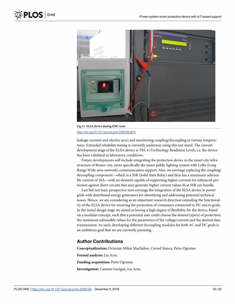
leakage currents and electric arcs) and monitoring coupling/decoupling at various tempera-
tures. Extended reliability testing is currently underway using this test stand. The current
development stage of the ELSA device is TRL 4 (Technology Readiness Level), i.e. the device
has been validated in laboratory conditions.
Future developments will include integrating the protection device in the smart city infra-
structure of Brasov city, more specifically the smart public lighting system with LoRa (Long
Range Wide-area network) communication support. Also, we envisage replacing the coupling/
decoupling component—which is a SSR (Solid State Relay) and thus has a maximum admissi-
ble current of 1kA—with an element capable of supporting higher currents for enhanced pro-
tection against short circuits that may generate higher current values th at SSR can handle.
Last but not least, prospective tests envisage the integration of the ELSA device in power
grids with distributed energy generators for identifying and addressing potential technical
issues. Hence, we are considering as an important research direction extending the functional-
ity of the ELSA device for ensuring the protection of consumers connected to DC micro-grids.
In the initial design stage we aimed at having a high degree of flexibility for the device, based
on a modular concept, such that a potential user could choose the desired type(s) of protection,
the maximum admissible values for the parameters of the voltage/current and the desired data
transmission. As such, developing different decoupling modules for both AC and DC grids is
an ambitious goal that we are currently pursuing.
Author Contributions
Conceptualization: Octavian Mihai Machidon, Cornel Stanca, Petre Ogrutan.
Formal analysis: Lia Aciu.
Funding acquisition: Petre Ogrutan.
Investigation: Carmen Gerigan, Lia Aciu.
Fig 13. ELSA device during EMC tests.
https://doi.org/10.1371/journal.pone.0208168.g013
Power-system smart protection device with IoT-based support
PLOS ONE | https://doi.org/10.1371/journal.pone.0208168 December 5, 2018 19 / 22

Methodology: Octavian Mihai Machidon, Cornel Stanca, Lia Aciu.
Project administration: Petre Ogrutan, Carmen Gerigan.
Software: Octavian Mihai Machidon, Carmen Gerigan.
Supervision: Petre Ogrutan.
Validation: Carmen Gerigan.
Writing – original draft: Octavian Mihai Machidon.
Writing – review & editing: Octavian Mihai Machidon.
References1. Yuan W, Zhao L, Zeng B. Optimal power grid protection through a defender–attacker–defender model.
Reliability Engineering & System Safety. 2014; 121:83–89. https://doi.org/10.1016/j.ress.2013.08.003
2. Liu J, Huang GM, Ma Z, Geng Y. A novel smart high-voltage circuit breaker for smart grid applications.
IEEE Transactions on Smart Grid. 2011; 2(2):254–264. https://doi.org/10.1109/TSG.2011.2134113
3. Sivaraman V, Gharakheili HH, Vishwanath A, Boreli R, Mehani O. Network-level security and privacy
control for smart-home IoT devices. In: Wireless and Mobile Computing, Networking and Communica-
tions (WiMob), 2015 IEEE 11th International Conference on. IEEE; 2015. p. 163–167.
4. Fernandez-Carames TM. An intelligent power outlet system for the smart home of the Internet of
Things. International Journal of Distributed Sensor Networks. 2015; 11(11):214805. https://doi.org/10.
1155/2015/214805
5. Mrazovac B, Bjelica MZ, Teslic N, Papp I. Towards ubiquitous smart outlets for safety and energetic effi-
ciency of home electric appliances. In: Consumer Electronics-Berlin (ICCE-Berlin), 2011 IEEE Interna-
tional Conference on. IEEE; 2011. p. 322–326.
6. Sankaranarayanan S, Wan AT. ABASH—Android based smart home monitoring using wireless sen-
sors. In: Clean Energy and Technology (CEAT), 2013 IEEE Conference on. IEEE; 2013. p. 494–499.
7. Ferrer HJA, Schweitzer EO. Modern solutions for protection, control, and monitoring of electric power
systems. Schweitzer Engineering Laboratories; 2010.
8. Launches E. Arc Fault Detection Device to Reduce Electrical Safety Risk, Eaton Company Press
Release;2016.
9. Kennedy J, Ciufo P, Agalgaonkar A. A review of protection systems for distribution networks embedded
with renewable generation. Renewable and Sustainable Energy Reviews. 2016; 58:1308–1317. https://
doi.org/10.1016/j.rser.2015.12.258
10. Rana MM, Li L. An overview of distributed microgrid state estimation and control for smart grids. Sen-
sors. 2015; 15(2):4302–4325. https://doi.org/10.3390/s150204302 PMID: 25686316
11. Mirsaeidi S, Said DM, Mustafa MW, Habibuddin MH, Ghaffari K. An analytical literature review of the
available techniques for the protection of micro-grids. International Journal of Electrical Power & Energy
Systems. 2014; 58:300–306. https://doi.org/10.1016/j.ijepes.2014.01.032
12. Mirsaeidi S, Dong X, Shi S, Wang B. AC and DC Microgrids: A Review on Protection Issues and
Approaches. Journal of Electrical Engineering & Technology. 2017; 12(6):2089–2098.
13. Fletcher S, Norman P, Galloway S, Burt G. Determination of protection system requirements for dc
unmanned aerial vehicle electrical power networks for enhanced capability and survivability. IET Electri-
cal Systems in Transportation. 2011; 1(4):137–147. https://doi.org/10.1049/iet-est.2010.0070
14. Hernandez J, Sutil F. Electric vehicle charging stations feeded by renewable: PV and train regenerative
braking. IEEE Latin America Transactions. 2016; 14(7):3262–3269. https://doi.org/10.1109/TLA.2016.
7587629
15. Baran ME, Mahajan NR. Overcurrent protection on voltage-source-converter-based multiterminal DC
distribution systems. IEEE transactions on power delivery. 2007; 22(1):406–412. https://doi.org/10.
1109/TPWRD.2006.877086
16. Hernandez JC, Sutil FS, Vidal PG. Protection of a multiterminal DC compact node feeding electric vehi-
cles on electric railway systems, secondary distribution networks, and PV systems. Turkish Journal of
Electrical Engineering & Computer Sciences. 2016; 24(4):3123–3143. https://doi.org/10.3906/elk-
1406-14
17. Das J. Power system analysis: short-circuit load flow and harmonics. CRC press; 2016.
Power-system smart protection device with IoT-based support
PLOS ONE | https://doi.org/10.1371/journal.pone.0208168 December 5, 2018 20 / 22

18. Sudhakar P, Malaji S, Sarvesh B. Reducing the impact of DG on distribution networks protection with
reverse power relay. Materials Today: Proceedings. 2018; 5(1):51–57. https://doi.org/10.1016/j.matpr.
2017.11.052
19. Maeston W, Ahn J. Composite multi-function relay system and its control method Patent available from:
https://patents.google.com/patent/KR101791255B1/en?q=triac&q=circuit+breaker&sort=new.
20. Wannous K, Toman P. IEC 61850 communication based distance protection. In: Electric Power Engi-
neering (EPE), Proccedings of the 2014 15th International Scientific Conference on. IEEE; 2014.
p. 107–112.
21. Ikegami H, Yerra RVP, Rajalakshmi P, Esaki H. Real time Power Capping with Smart Circuit Breaker to
maximize Power Utilization of Local Generator. In: Computer Software and Applications Conference
(COMPSAC), 2015 IEEE 39th Annual. vol. 3. IEEE; 2015. p. 505–510.
22. Radmanesh H, Kavousi A. Aircraft electrical power distribution system protection using smart circuit
breaker. IEEE Aerospace and Electronic Systems Magazine. 2017; 32(1):30–40. https://doi.org/10.
1109/MAES.2017.150172
23. Khandare P, Deokar S, Dixit A. Advanced technique in micro grid protection for various fault by using
numerical relay. In: Convergence in Technology (I2CT), 2017 2nd International Conference for. IEEE;
2017. p. 803–807.
24. Bhardwaj MK, Shimi S, Chatterji S. Design and Implementation of Multi Agent System in IDAPS Micro
Grid for Optimal Load Scheduling Network. International Journal of Advanced Technology in Engineer-
ing and Science. 2015; 3(04).
25. Abhijith S, George RJ, Prasad S, Paul E. Smart ultra fast acting electroinc circuit breaker. International
Research Journal of Engineering and Technology (IRJET). 2017; 4.
26. Liu S, Chen B, Zourntos T, Kundur D, Butler-Purry K. A coordinated multi-switch attack for cascading
failures in smart grid. IEEE Transactions on Smart Grid. 2014; 5(3):1183–1195. https://doi.org/10.1109/
TSG.2014.2302476
27. Chan M, Estève D, Escriba C, Campo E. A review of smart homes—Present state and future chal-
lenges. Computer methods and programs in biomedicine. 2008; 91(1):55–81. https://doi.org/10.1016/j.
cmpb.2008.02.001 PMID: 18367286
28. Piyare R. Internet of things: ubiquitous home control and monitoring system using android based smart
phone. International Journal of Internet of Things. 2013; 2(1):5–11.
29. Chilipirea C, Ursache A, Popa DO, Pop F. Energy efficiency and robustness for IoT: building a smart
home security system. In: Intelligent Computer Communication and Processing (ICCP), 2016 IEEE
12th International Conference on. IEEE; 2016. p. 43–48.
30. Huang LC, Chang HC, Chen CC, Kuo CC. A ZigBee-based monitoring and protection system for build-
ing electrical safety. Energy and Buildings. 2011; 43(6):1418–1426. https://doi.org/10.1016/j.enbuild.
2011.02.001
31. Komninos N, Philippou E, Pitsillides A. Survey in smart grid and smart home security: Issues, chal-
lenges and countermeasures. IEEE Communications Surveys & Tutorials. 2014; 16(4):1933–1954.
https://doi.org/10.1109/COMST.2014.2320093
32. Kola-Bezka M, Czupich M, Ignasiak-Szulc A. Smart Cities in Central and Eastern Europe: Viable future
or Unfulfilled Dream. Journal of International Studies. 2016; 9(1):76–87. https://doi.org/10.14254/2071-
8330.2016/9-1/6
33. Bischof S, Karapantelakis A, Nechifor CS, Sheth AP, Mileo A, Barnaghi P. Semantic modelling of smart
city data. W3C Workshop on the Web of Things—Enablers and services for an open Web of Devices.
2014;Berlin, Germany.
34. Rotuna CI, Cirnu CE, Gheorghita A. Implementing Smart City Solutions: Smart City Map and City Drop.
Quality of Life. 2017; 28(3):313–327.
35. Machidon OM, Andrei RC, Gerigan C. Smart Circuit Breaker Communication Infrastructure. TEM Jour-
nal-Technology Education Management Informatics. 2017; 6(4):855–861.
36. Jacobsen RH, Torring N, Danielsen BV, Hansen MT, Pedersen EB. Towards an app platform for data
concentrators. ISGT 2014. 2014;Washington DC, USA:1–5.
37. Kim DS, Lee SY, Wang KY, Choi JC, Chung DJA. Power Line Communication Modem Based on Adap-
tively Received Signal Detection for Networked Home Appliances. IEEE Transactions on Consumer
Electronics. 2007; 53(3):864–870. https://doi.org/10.1109/TCE.2007.4341558
38. Castellani AP, Dissegna M, Bui N, Zorzi M. WebIoT: A web application framework for the internet of things.
In Wireless Communications and Networking Conference Workshops (WCNCW). 2012; p. 202–207.
39. Zorzi M, Gluhak A, Lange S, Bassi A. From today’s intranet of things to a future internet of things: a wire-
less-and mobility-related view. IEEE Wireless Communications. 2010; 17:6. https://doi.org/10.1109/
MWC.2010.5675777
Power-system smart protection device with IoT-based support
PLOS ONE | https://doi.org/10.1371/journal.pone.0208168 December 5, 2018 21 / 22
40. Bui N, Castellani AP, Casari P, Zorzi M. The internet of energy: a web-enabled smart grid system. IEEE
Network. 2012; 26:4. https://doi.org/10.1109/MNET.2012.6246751
41. Lobo F, Cabello A, Lopez A, Mora D, Mora R. Distribution network as communication system. In CIRED
Seminar SmartGrids for Distribution IET-CIRED. 2008; p. 1–4.
42. Bressan N, Bazzaco L, Bui N, Casari P, Vangelista L, Zorzi M. The deployment of a smart monitoring
system using wireless sensor and actuator networks. in IEEE Int Conf on Smart Grid Communications
(SmartGridComm. 2010; p. 49–54.
43. Williams T. Standards in EMC for Product Designers: Meeting the European EMC Directive.
Newnes;2014.
Power-system smart protection device with IoT-based support
PLOS ONE | https://doi.org/10.1371/journal.pone.0208168 December 5, 2018 22 / 22