POWER SYSTEM PROTECTION Course Code: EEE 64 Causes of …
19
PSP EEE64 Mohan B S NHCE, Bangalore Dept of EEE AY: 2019-2020 POWER SYSTEM PROTECTION Course Code: EEE64 MODULE 3 Protection against over voltages Causes of Over voltage in Power System Increase in voltage for the very short time in power system is called as the over voltage. it is also known as the voltage surge or voltage transients. The voltage stress caused by over voltage can damage the lines and equipment’s connected to the system, There are two types of causes of over voltage in power system. 1. Over voltage due to external causes 2. Over voltage due to internal causes Transient over voltages can be generated at high frequency (load switching and lightning), medium frequency (capacitor energizing), or low frequency. Over voltage due to External causes: This cause of over voltage in power system is the lightning strokes in the cloud. Now, how lightning strokes are produced. So when electric charges get accumulated in clouds due to thunder Strom caused due to some bad atmosphere process. This type of over voltages originates from atmospheric disturbances, mainly due to lightning. This takes the form of a surge and has no direct relationship with the operating voltage of the line. It may be due to any of the following causes: A) Direct lightning stroke B) Electromagnetically induced over voltages due to lightning discharge taking place near the line, called ‘side stroke’. C) Voltages induced due to atmospheric changes along the length of the line. D) Electrostatically induced voltages due to presence of charged clouds nearby. E) Electrostatically induced over voltages due to the frictional effects of small particles like dust or dry snow in the atmosphere or due to change in the altitude of the line. The potential between the clouds and earth breaks down and lightning flash takes place between the cloud and ground when this voltage becomes 5 to 20 million volts or when the potential gradient becomes 5000V to 10000V per cm. There are two types of lightning strokes. 1. Direct lightning strokes 2. Indirect lightning stroke Internal Over voltages These over voltages are caused by changes in the operating conditions of the power system. These can be divided into two groups as below: 1. Switching over voltages or Transient over operation voltages of high frequency: This is caused when switching operation is carried out under normal conditions or when fault occurs in the network. When an unloaded long line is charged, due to Ferranti Effect the receiving end voltage is increased considerably
Transcript of POWER SYSTEM PROTECTION Course Code: EEE 64 Causes of …

PSP EEE64 Mohan B S
NHCE, Bangalore Dept of EEE AY: 2019-2020
POWER SYSTEM PROTECTION
Course Code: EEE64
MODULE 3
Protection against over voltages
Causes of Over voltage in Power System Increase in voltage for the very short time in power system is called as the over voltage. it is also known as the
voltage surge or voltage transients. The voltage stress caused by over voltage can damage the lines and
equipment’s connected to the system, There are two types of causes of over voltage in power system.
1. Over voltage due to external causes
2. Over voltage due to internal causes
Transient over voltages can be generated at high frequency (load switching and lightning), medium frequency
(capacitor energizing), or low frequency.
Over voltage due to External causes:
This cause of over voltage in power system is the lightning strokes in the cloud.
Now, how lightning strokes are produced. So when electric charges get accumulated in clouds due to thunder
Strom caused due to some bad atmosphere process.
This type of over voltages originates from atmospheric disturbances, mainly due to lightning. This takes the form
of a surge and has no direct relationship with the operating voltage of the line.
It may be due to any of the following causes:
A) Direct lightning stroke
B) Electromagnetically induced over voltages due to lightning discharge taking place near the line, called ‘side
stroke’. C) Voltages induced due to atmospheric changes along the length of the line.
D) Electrostatically induced voltages due to presence of charged clouds nearby.
E) Electrostatically induced over voltages due to the frictional effects of small particles like dust or dry snow in
the atmosphere or due to change in the altitude of the line.
The potential between the clouds and earth breaks down and lightning flash takes place between the cloud and
ground when this voltage becomes 5 to 20 million volts or when the potential gradient becomes 5000V to
10000V per cm.
There are two types of lightning strokes.
1. Direct lightning strokes
2. Indirect lightning stroke
Internal Over voltages These over voltages are caused by changes in the operating conditions of the power system. These can be divided into
two groups as below:
1. Switching over voltages or Transient over operation voltages of high frequency:
This is caused when switching operation is carried out under normal conditions or when fault occurs in the network.
When an unloaded long line is charged, due to Ferranti Effect the receiving end voltage is increased considerably

PSP EEE64 Mohan B S
NHCE, Bangalore Dept of EEE AY: 2019-2020
resulting in over voltage in the system. Similarly when the primary side of the transformers or reactors is switched on,
over voltage of transient nature occurs.
2. Temporary over voltages:
These are caused when some major load gets disconnected from the long line under normal or steady state condition.
The protective devices against Travelling Wave are discussed below
PSP EEE64 Mohan B S
NHCE, Bangalore Dept of EEE AY: 2019-2020
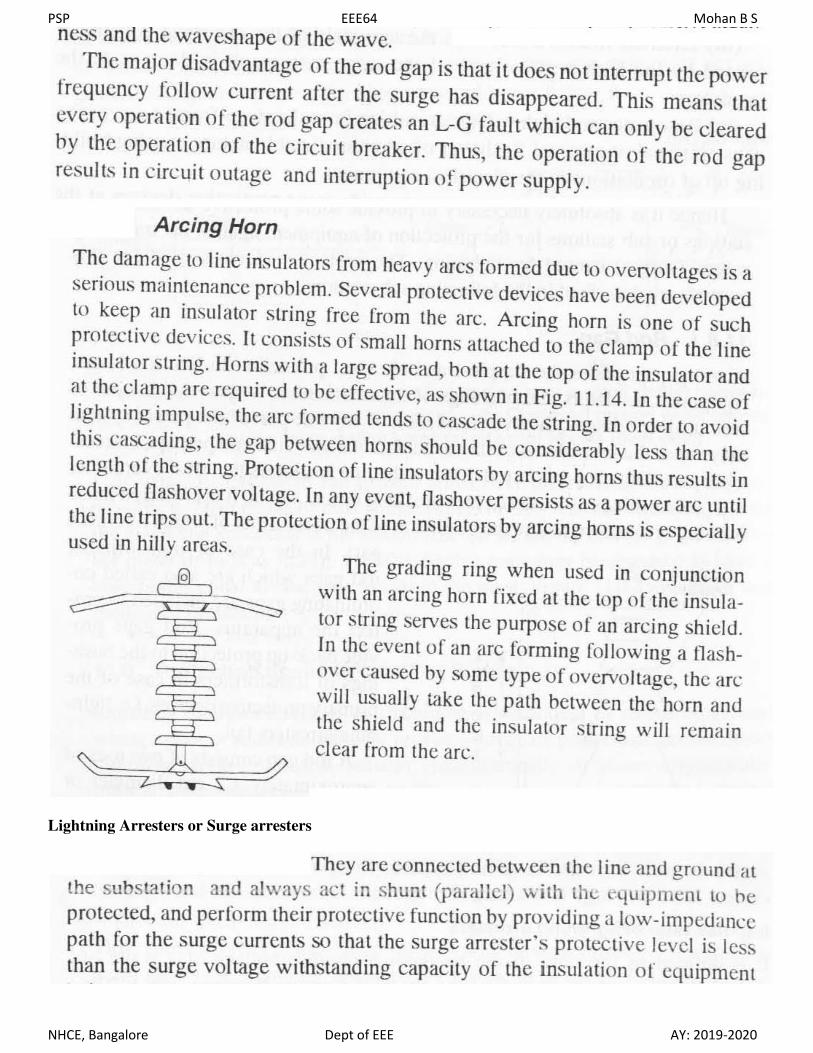
Lightning Arresters or Surge arresters

PSP EEE64 Mohan B S
NHCE, Bangalore Dept of EEE AY: 2019-2020

PSP EEE64 Mohan B S
NHCE, Bangalore Dept of EEE AY: 2019-2020
Expulsion Type Lightning Arrester:
It consists of an arc extinguishing chamber in series with an air gap. The arc extinguishing chamber is in the
form of fiber tube which interrupts the arc after discharging the surge by the generation of gasses.
When a voltage surge occurs that is sufficient to spark over the series
gap and the gap in the fiber tube, discharge current flows to ground.
The arc in the tube attacks some of the fiber of tube walls, releasing a
large amount of a relatively cool, non-conducting gas.
The gas produced in fiber tube acts not only to extinguish the arc but
also builds up high pressure and expelled through the lower electrode
which is hollow. As the gas leaves the tube violently, it wipes out the
ionized air around the arc.
Due to this strong deionization effect, arc goes out at current zero instant
and will not be re-established.
An expulsion type lightning arrester has a current rating in addition to
the voltage rating. The maximum current rating must be equal to the short-circuit current available at the point of
installation. These are generally used on towers for the protection of transmission lines.
Advantages
They are not very expensive.
They are improved form of rod gap arresters as they block the flow of power frequency follow currents
They can be easily installed.
Limitations
An expulsion type arrester can perform only limited number of operations as during each operation some
of the fiber material is used up.
This type of arrester cannot be mounted on enclosed equipment due to discharge of gases during
operation.
Due to the poor volt/am characteristic of the arrester, it is not suitable for protection of expensive
equipment

PSP EEE64 Mohan B S
NHCE, Bangalore Dept of EEE AY: 2019-2020
Non-linear Surge Diverter:
It consists of an outer ceramic body containing a set of resistances (valves) and spark gaps in series. The
resistances are made of a special silicon carbide ceramic.

PSP EEE64 Mohan B S
NHCE, Bangalore Dept of EEE AY: 2019-2020
PSP EEE64 Mohan B S
NHCE, Bangalore Dept of EEE AY: 2019-2020
Metal-Oxide Surge Arrester:

PSP EEE64 Mohan B S
NHCE, Bangalore Dept of EEE AY: 2019-2020

PSP EEE64 Mohan B S
NHCE, Bangalore Dept of EEE AY: 2019-2020
Insulation Coordination: Insulation coordination (IC) is the correlation of the insulation of various equipments to be protected
(transformer, CB-Circuit Breaker, bus bar etc) with the characteristics of protective devices (Lightning Arrestors
(LA), gaps, etc) such that the main equipments are always protected against over voltages (O/Vs).
Insulation of the various equipments in a power system to the insulation of the protective devices used for the
protection of those equipments against over-voltage.
To assist the process of IC, standard insulation levels have been recommended. They are
1. BIL-Basic Impulse Insulation Levels
2. SIL - Switching Impulse Insulation levels.
Insulators in some points are easily replaceable and repairable compared to other.
Insulation in some points are not so easily replaceable and repairable and the replacement and repairing may be
highly expensive and require long interruption of power. Moreover failure of insulator at these points may causes
bigger part of electrical network to be out of service. So, it is desirable that in situation of insulator failure,
only the easily replaceable and repairable insulator fails.
The overall aim of insulation coordination is to reduce to an economically and operationally acceptable level the
cost and disturbance caused by insulation failure. In insulation coordination method, the insulation of the various
parts of the system must be so graded that flash over if occurs it must be at intended points.
Component of electrical power system may suffer from different level of transient voltage stresses, switching
impulse voltage and lightning impulse voltage.
The maximum amplitude of transient over voltages reach the components, can be limited by using protecting
device like lightning arrestors in the system.
If we maintain the insulation level of all the power system component above the protection level of protective
device, then ideally there will be no chance of breakdown of insulation of any component. Since the transient
over voltage reaches at the insulation after crossing the surge protective devices will have amplitude equals to
protection level voltage and protection level voltage impulse insulation level of the components.
The insulation coordination is thus the matching of the volt-time flashover and breakdown characteristics of
equipments an protective devices, in order to obtain maximum protective margin at a reasonable cost.
Fig.1 shown construction of volt-time curve and the terminology associated with impulse testing

PSP EEE64 Mohan B S
NHCE, Bangalore Dept of EEE AY: 2019-2020
Construction of volt-time curve is based on application of impulse voltages of the same wave shape but of
different peak values to the insulation whose volt-time curve is required.
If an impulse voltage and polarity is adjusted so that test specimen (insulation) flashes over on the front pf the
wave, the value of voltage corresponding to the point on front of the wave at which flashover occurs is called
front flashover.
If an impulse voltage of same waveshape is adjusted so that the test spicimen flashes over on the tail of the wave
at 50 % of the application and fails to flashover on the other 50% of the applications, the creat value of this
voltage is called the critical flashover voltage.
If an impulse voltage causes flashover of the test specimen exaclty at the creat value, then it is called flashover.
If the flashover does not take place, the wave is called a full wave and if flashover does take place, the wave is
called chopped wave.
the applied impulse voltage reduced to just below flashover voltage of the test specimen is called the "critical
withstand voltage.
The rated withstand voltage is the crest value of the impulse wave that the test specimen will withstand
disruptive discharged.
Basic Impulse Insulation Level (B.I.L)
Fig.1

PSP EEE64 Mohan B S
NHCE, Bangalore Dept of EEE AY: 2019-2020
Neutral Grounding
In power system, grounding or earthing means connecting frame of electrical equipment (non-current carrying
part) or some electrical part of the system (e.g. neutral point in a star-connected system, one conductor of the
secondary of a transformer etc.) to earth i.e. soil. This connection to earth may be through a conductor or some
other circuit element (e.g. a resistor, a circuit breaker etc.) depending upon the situation. Regardless of the
method of connection to earth, grounding or earthing offers two principal advantages.
First, it provides protection to the power system. For example, if the neutral point of a star-connected
system is grounded through a circuit breaker and phase to earth fault occurs on any one line, a large fault
current will flow through the circuit breaker. The circuit breaker will open to isolate the faulty line. This
protects the power system from the harmful effects of the fault.
Secondly, earthing of electrical equipment (e.g. domestic appliances, hand-held tools, industrial motors
etc.) ensures the safety of the persons handling the equipment. For example, if insulation fails, there will
be a direct contact of the live conductor with the metallic part (i.e. frame) of the equipment. Any person
in contact with the metallic part of this equipment will be subjected to a dangerous electrical shock which
can be fatal. In this chapter, we shall discuss the importance of grounding or earthing in the line of power
system with special emphasis on neutral grounding.
The process of connecting the metallic frame (i.e. non-current carrying part) of electrical equipment or some
electrical part of the system (e.g. neutral point in a star-connected system, one conductor of the secondary of a
transformer etc.) to earth is called grounding or earthing.
System Grounding
PSP EEE64 Mohan B S
NHCE, Bangalore Dept of EEE AY: 2019-2020
The process of connecting some electrical part of the power system (e.g. neutral point of a star connected
system, one conductor of the secondary of a transformer etc.) to earth (i.e. soil) is called system grounding.
By adopting proper schemes of system grounding, we can achieve many advantages including protection,
reliability and safety to the power system network. But before discussing the various aspects of neutral
grounding, it is desirable to give two examples to appreciate the need of system grounding.
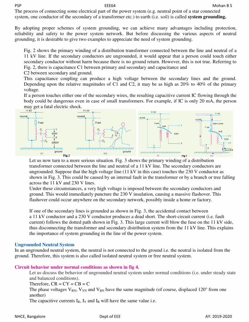
Fig. 2 shows the primary winding of a distribution transformer connected between the line and neutral of a
11 kV line. If the secondary conductors are ungrounded, it would appear that a person could touch either
secondary conductor without harm because there is no ground return. However, this is not true. Referring to
Fig. 2, there is capacitance C1 between primary and secondary and capacitance and
C2 between secondary and ground.
This capacitance coupling can produce a high voltage between the secondary lines and the ground.
Depending upon the relative magnitudes of C1 and C2, it may be as high as 20% to 40% of the primary
voltage.
If a person touches either one of the secondary wires, the resulting capacitive current IC flowing through the
body could be dangerous even in case of small transformers. For example, if IC is only 20 mA, the person
may get a fatal electric shock.
Let us now turn to a more serious situation. Fig. 3 shows the primary winding of a distribution
transformer connected between the line and neutral of a 11 kV line. The secondary conductors are
ungrounded. Suppose that the high voltage line (11 kV in this case) touches the 230 V conductor as
shown in Fig. 3. This could be caused by an internal fault in the transformer or by a branch or tree falling
across the 11 kV and 230 V lines.
Under these circumstances, a very high voltage is imposed between the secondary conductors and
ground. This would immediately puncture the 230 V insulation, causing a massive flashover. This
flashover could occur anywhere on the secondary network, possibly inside a home or factory.
If one of the secondary lines is grounded as shown in Fig. 3, the accidental contact between
a 11 kV conductor and a 230 V conductor produces a dead short. The short-circuit current (i.e. fault
current) follows the dotted path shown in Fig. 3. This large current will blow the fuse on the 11 kV side,
thus disconnecting the transformer and secondary distribution system from the 11 kV line. This explains
the importance of system grounding in the line of the power system.
Ungrounded Neutral System
In an ungrounded neutral system, the neutral is not connected to the ground i.e. the neutral is isolated from the
ground. Therefore, this system is also called isolated neutral system or free neutral system.
Circuit behavior under normal conditions as shown in fig 4.
Let us discuss the behavior of ungrounded neutral system under normal conditions (i.e. under steady state
and balanced conditions).
Therefore, CR = CY = CB = C
The phase voltages VRN, VYN and VBN have the same magnitude (of course, displaced 120° from one
another)
The capacitive currents IR, IY and IB will have the same value i.e.

PSP EEE64 Mohan B S
NHCE, Bangalore Dept of EEE AY: 2019-2020
The capacitive currents IR, IY and IB lead their respective phase voltages VRN, VYN and VBN by
90° as shown in the phasor diagram in Fig. 4. The three capacitive currents are equal in magnitude and
are displaced 120° from each other. Therefore, their phasor sum is zero. As a result, no current flows to
ground and the potential of neutral is the same as the ground potential. Therefore, ungrounded neutral
system poses no problems under normal conditions. However, as we shall see, currents and voltages are
greatly influenced during fault conditions.
Circuit behavior under single line to ground-fault. Let us discuss the behavior of ungrounded neutral system when single line to ground fault occurs.
Suppose line to ground fault occurs in line B at some point F. The circuit then becomes as shown in
Fig.5.
The capacitive currents IR and IY flow through the lines R and Y respectively. The voltages driving IR
and IY are VBR and VB Y respectively. Note that VBR and VB Y are the line voltages.
The paths of IR and IY are essentially capacitive. Therefore, IR leads VBR by 90° and IY leads VB Y by
90°. The capacitive fault current IC in line B is the phasor sum of IR and IY
Therefore, when single line to ground fault occurs on an ungrounded neutral system, the following
effects are produced in the system:
(i) The potential of the faulty phase becomes equal to ground potential. However, the voltages of the two
remaining healthy phases rise from their normal phase voltages to full line value. This may result in
insulation breakdown.
(ii) The capacitive current in the two healthy phases increase to 3 times the normal value.
(iii) The capacitive fault current (IC) becomes 3 times the normal per phase capacitive current.

PSP EEE64 Mohan B S
NHCE, Bangalore Dept of EEE AY: 2019-2020
(iv) This system cannot provide adequate protection against earth faults. It is because the capacitive fault
current is small in magnitude and cannot operate protective devices.
(v) The capacitive fault current IC flows into earth. Experience shows that IC in excess of 4A is sufficient
to maintain an arc in the ionized path of the fault. If this current is once maintained, it may exist even
after the earth fault is cleared. This phenomenon of persistent arc is called arcing ground.
Due to arcing ground, the system capacity is charged and discharged in a cyclic order. This sets up high-
frequency oscillations on the whole system and the phase voltage of healthy conductors may rise to 5 to 6
times its normal value.
Neutral Grounding
The process of connecting neutral point of 3-phase system to earth (i.e. soil) either directly or through some
circuit element (e.g. resistance, reactance etc.) is called neutral grounding.
Neutral grounding provides protection to personal and equipment. It is because during earth fault, the
current path is completed through the earthed neutral and the protective devices (e.g. a fuse etc.) operate
to isolate the faulty conductor from the rest of the system.
Fig. 6 shows a 3-phase, star-connected system with neutral
earthed (i.e. neutral point is connected to soil).
Suppose a single line to ground fault occurs in line R at
point F. This will cause the current to flow through ground
path.
The current flows from Rphase to earth, then to neutral
point N and back to R-phase.
Since the impedance of the current path is low, a large
current flows through this path. This large current will
blow the fuse in R-phase and isolate the faulty line R. This will protect the system from the harmful
effects (e.g. damage to equipment, electric shock to personnel etc.) of the fault.
One important feature of grounded neutral is that the potential difference between the live conductor and
ground will not exceed the phase voltage of the system i.e. it will remain nearly constant
Advantages of Neutral Grounding
(i) Voltages of the healthy phases do not exceed line to ground voltages i.e. they remain nearly constant.
(ii) The high voltages due to arcing grounds are eliminated.
(iii) The protective relays can be used to provide protection against earth faults. In case earth fault occurs
on any line, the protective relay will operate to isolate the faulty line.
(iv) The overvoltages due to lightning are discharged to earth.
(v) It provides greater safety to personnel and equipment.
(vi) It provides improved service reliability.
(vii) Operating and maintenance expenditures are reduced.
Methods of Neutral Grounding
The methods commonly used for grounding the neutral point of a 3-phase system are :
(i) Solid or effective grounding (ii) Resistance grounding
(iii) Reactance grounding (iv) Peterson-coil grounding
The choice of the method of grounding depends upon many factors including the size of the system,
system voltage and the scheme of protection to be used.
Solid Grounding
When the neutral point of a 3-phase system (e.g. 3- phase generator, 3-phase transformer etc.) is directly
connected to earth (i.e. soil) through a wire of negligible resistance and reactance, it is called solid
grounding or effective grounding.
PSP EEE64 Mohan B S
NHCE, Bangalore Dept of EEE AY: 2019-2020
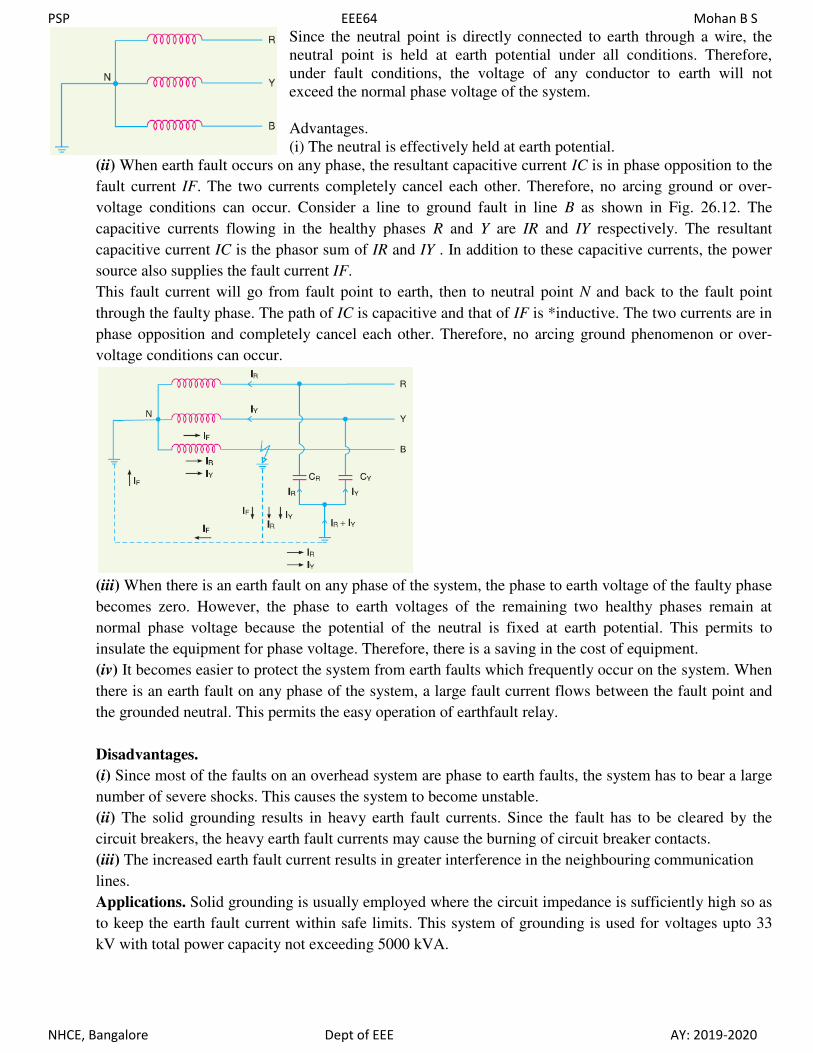
Since the neutral point is directly connected to earth through a wire, the
neutral point is held at earth potential under all conditions. Therefore,
under fault conditions, the voltage of any conductor to earth will not
exceed the normal phase voltage of the system.
Advantages.
(i) The neutral is effectively held at earth potential.
(ii) When earth fault occurs on any phase, the resultant capacitive current IC is in phase opposition to the
fault current IF. The two currents completely cancel each other. Therefore, no arcing ground or over-
voltage conditions can occur. Consider a line to ground fault in line B as shown in Fig. 26.12. The
capacitive currents flowing in the healthy phases R and Y are IR and IY respectively. The resultant
capacitive current IC is the phasor sum of IR and IY . In addition to these capacitive currents, the power
source also supplies the fault current IF.
This fault current will go from fault point to earth, then to neutral point N and back to the fault point
through the faulty phase. The path of IC is capacitive and that of IF is *inductive. The two currents are in
phase opposition and completely cancel each other. Therefore, no arcing ground phenomenon or over-
voltage conditions can occur.
(iii) When there is an earth fault on any phase of the system, the phase to earth voltage of the faulty phase
becomes zero. However, the phase to earth voltages of the remaining two healthy phases remain at
normal phase voltage because the potential of the neutral is fixed at earth potential. This permits to
insulate the equipment for phase voltage. Therefore, there is a saving in the cost of equipment.
(iv) It becomes easier to protect the system from earth faults which frequently occur on the system. When
there is an earth fault on any phase of the system, a large fault current flows between the fault point and
the grounded neutral. This permits the easy operation of earthfault relay.
Disadvantages.
(i) Since most of the faults on an overhead system are phase to earth faults, the system has to bear a large
number of severe shocks. This causes the system to become unstable.
(ii) The solid grounding results in heavy earth fault currents. Since the fault has to be cleared by the
circuit breakers, the heavy earth fault currents may cause the burning of circuit breaker contacts.
(iii) The increased earth fault current results in greater interference in the neighbouring communication
lines.
Applications. Solid grounding is usually employed where the circuit impedance is sufficiently high so as
to keep the earth fault current within safe limits. This system of grounding is used for voltages upto 33
kV with total power capacity not exceeding 5000 kVA.

PSP EEE64 Mohan B S
NHCE, Bangalore Dept of EEE AY: 2019-2020
Resistance Grounding
In order to limit the magnitude of earth fault current, it is a common practice to connect the neutral point
of a 3-phase system to earth through a resistor. This is called resistance grounding.
The value of R should neither be very low nor very high. If the value of earthing
resistance R is very low, the earth fault current will be large and the system
becomes similar to the solid grounding system.
On the other hand, if the earthing resistance R is very high, the system
conditions become similar to ungrounded neutral system. The value of R is so
chosen such that the earth fault current is limited to safe value but still sufficient
to permit the operation of earth fault protection system.
In practice, that value of R is selected that limits the earth fault current to 2 times the normal full load current of
the earthed generator or transformer.
Advantages.
(i) By adjusting the value of R, the arcing grounds can be minimized.
(ii) The earth fault current is small due to the presence of earthing resistance. Therefore, interference with
communication circuits is reduced.
(iii) It improves the stability of the system.
Disadvantages.
(i) Since the system neutral is displaced during earth faults, the equipment has to be insulated for higher
voltages.
(ii) This system is costlier than the solidly grounded system.
(iii) A large amount of energy is produced in the earthing resistance during earth faults. Sometimes it becomes
difficult to dissipate this energy to atmosphere.
Applications. It is used on a system operating at voltages between 2.2 kV and 33 kV with power source capacity
more than 5000 kVA.
Reactance Grounding
In this system, a reactance is inserted between the neutral and ground. The purpose of reactance is to limit the
earth fault current. By changing the earthing reactance, the earth fault current
can to changed to obtain the conditions similar to that of solid grounding.
This method is not used these days because of the following disadvantages :
(i) In this system, the fault current required to operate the protective device is
higher than that of resistance grounding for the same fault conditions.
(ii) High transient voltages appear under fault conditions.
Arc Suppression Coil Grounding (or Resonant Grounding or Peterson coil or Earth fault neutralizer)
We have seen that capacitive currents are responsible for producing arcing grounds.
These capacitive currents flow because capacitance exists between each line and earth.
If inductance L of appropriate value is connected in parallel with the
capacitance of the system, the fault current IF flowing through L will be in
phase opposition to the capacitive current IC of the system.
If L is so adjusted that IL = IC, then resultant current in the fault will be
zero. This condition is known as resonant grounding.
When the value of L of arc suppression coil is such that the fault current IF
exactly balances the capacitive current IC, it is called resonant grounding.
PSP EEE64 Mohan B S
NHCE, Bangalore Dept of EEE AY: 2019-2020
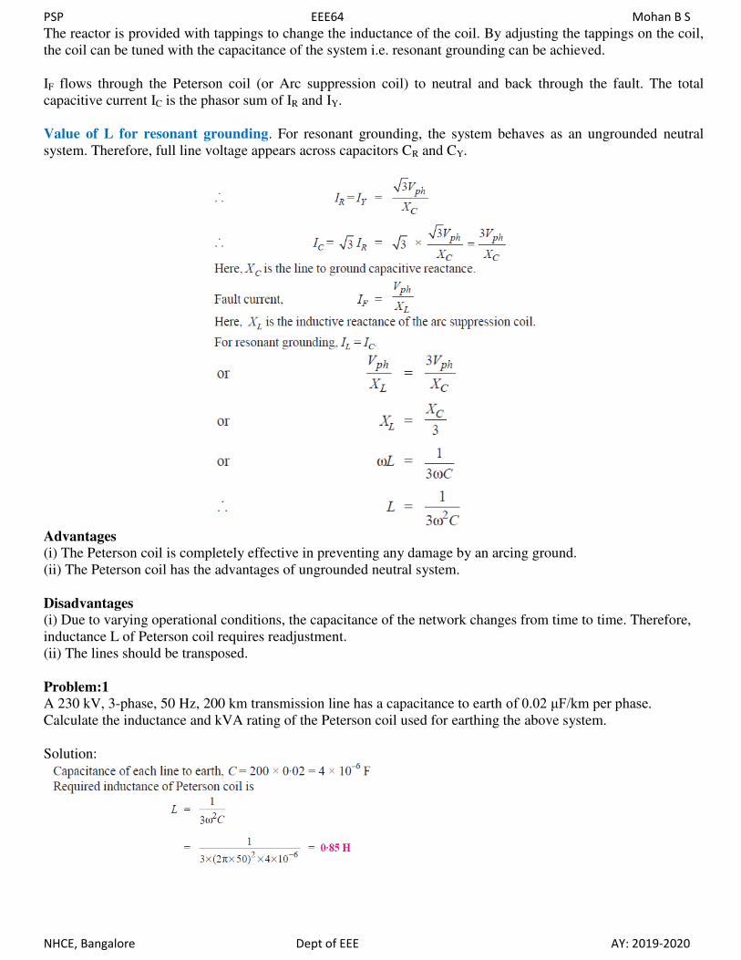
The reactor is provided with tappings to change the inductance of the coil. By adjusting the tappings on the coil,
the coil can be tuned with the capacitance of the system i.e. resonant grounding can be achieved.
IF flows through the Peterson coil (or Arc suppression coil) to neutral and back through the fault. The total
capacitive current IC is the phasor sum of IR and IY.
Value of L for resonant grounding. For resonant grounding, the system behaves as an ungrounded neutral
system. Therefore, full line voltage appears across capacitors CR and CY.
Advantages
(i) The Peterson coil is completely effective in preventing any damage by an arcing ground.
(ii) The Peterson coil has the advantages of ungrounded neutral system.
Disadvantages
(i) Due to varying operational conditions, the capacitance of the network changes from time to time. Therefore,
inductance L of Peterson coil requires readjustment.
(ii) The lines should be transposed.
Problem:1
A 230 kV, 3-phase, 50 Hz, 200 km transmission line has a capacitance to earth of 0.02 μF/km per phase. Calculate the inductance and kVA rating of the Peterson coil used for earthing the above system.
Solution:

PSP EEE64 Mohan B S
NHCE, Bangalore Dept of EEE AY: 2019-2020
Problem2:
A 50 Hz overhead line has line to earth capacitance of 1.2 μF. It is desired to use *earth fault neutralizer.
Determine the reactance to neutralize the capacitance of (i) 100% of the length of the line (ii) 90% of the length
of the line and (iii) 80% of the length of the line.
Solution:
Problem3:
A 132 kV, 3-phase, 50 Hz transmission line 200 km long consists of three conductors of effective diameter 20
mm arranged in a vertical plane with 4 m spacing and regularly transposed. Find the inductance and kVA rating
of the arc suppression coil in the system.
Solution:
Radius of conductor, r = 20/2 = 10 mm = 0.01 m


![A Romantic Jazz Suite [C118] - Free-scores.com : World Free … · eee eee e eee )o 2e %e&o %vq i r x m ± ± m ± ± ± ± ± m ± ± m ± ± ± ± ± " eee eee e eee)o 2e %e&o %vq](https://static.fdocuments.in/doc/165x107/60a6220791891f1ffb1e5d23/a-romantic-jazz-suite-c118-free-world-free-eee-eee-e-eee-o-2e-eo-vq.jpg)