Power-System Level Classification of Voltage-Source HVDC ...
14
IET Research Journals Power-System Level Classification of Voltage-Source HVDC Converter Stations Based Upon DC Fault Handling Capabilities ISSN 1751-8644 doi: 0000000000 www.ietdl.org P. D. Judge 1* G. Chaffey 2 M. Wang 2 F. Z. Dejene 2 J. Beerten 2 T. C. Green 3 D. Van Hertem 2 W. Leterme 2 1 Institute of Energy Systems, School of Engineering, University of Edinburgh, EH9 3DW, U.K. 2 EnergyVille/Electa Research Group, Electrical Engineering Department ESAT, KU Leuven, Heverlee 3001, Belgium 3 Department of Electrical and Electronic Engineering, Imperial College, London SW7 2AZ, U.K. * E-mail: [email protected] Abstract: To date, numerous concepts for converter station designs for use in Voltage Source Converter (VSC) based high-voltage direct current (HVDC) systems have been proposed. These differ not only in converter circuit topology, sub-module design and control scheme, but also in AC-or-DC switchgear and other auxiliary equipment. In the main, the existing literature categorises these converter stations according to just the converter circuit technologies and controls. However, for the development of network codes and to enable systematic network studies, a system-focused and technology-independent classification is needed. As such a classification does not yet exist, this paper proposes a new framework which categorises VSC station designs according to their capabilities during a DC-side fault and the method by which post-fault restoration may be achieved, given that these are the main differentiating factors from a system perspective. The classification comprises six converter station types and three time-intervals through which to fully characterise a design. Many well-known forms of converters are used as case studies, and simulation results are used to exemplify the classification framework. The outcome is a generic and technology-independent way of characterising converter station designs that is useful in wider power-system analysis but also for putting proposed converter stations into context. 1 Introduction Voltage Source Converter (VSC) based HVDC systems are increas- ingly used in modern power systems and are a key-technology for directly integrating renewable technologies into modern power sys- tems [1, 2], as well as unlocking the system flexibility required to facilitate wide-scale system integration of renewable resources [3]. They are used as point-to-point links between asynchronous AC net- works, connections of offshore renewable energy sources, embedded links for transmission infrastructure enhancement, and in the form of multi-terminal HVDC networks which combine several or all of these applications [4, 5]. For these VSC HVDC systems, the Modular Multilevel Converter (MMC) [6, 7] has emerged as the dominant converter topology, supplanting previous generations of two- and three-level converters due to its high efficiency, controllability and modular design. This topology has been explored in detail in the literature, with focus on sub-module (SM) design [8–14], control design [15–18] and capac- itor sizing [19–21]. Numerous other converter topologies derived from the MMC have also been proposed, either with different SM types [22, 23] or hybrid topologies [24–28]. As MMC-based VSC systems increase in maturity, efficiency, voltage level and fault handling, the extension to multi-terminal and meshed HVDC networks is increasingly considered [5]. At present, two multi-terminal HVDC networks have already been implemented, albeit at relatively low overall power [29, 30]. The Zhangbei HVDC grid project is expected to be the world’s first multi-gigawatt multi-terminal VSC HVDC network, with a com- bined overall power processing capability of 7.5 GW [31]. One of the key remaining challenges in implementing multi-terminal and meshed HVDC networks is the requirement for the system to react to DC-side faults in ways that preserve as much of the original functionality of the network as possible. The converter station - formed of the VSC plus any AC or DC switchgear and additional auxiliary circuits - can give rise to widely different responses to, and capabilities during and after, a DC-side fault. Currently, many different technologies for clearing DC-side faults have been proposed by both industry and academia. These make use of various converter design options [24, 32, 33], fault clearing equipment such as AC or DC circuit breakers [34–39], or other auxiliary equipment [40]. Furthermore, numerous options for converter control exist, increasing the number of possible converter responses during and after a DC-side fault [41, 42]. The responses and capabilities of the converter station impact sev- eral network performance criteria, including the duration for which fault current is fed from the AC-side of the converter station, the reactive power support that the converter station is capable of provid- ing to the AC system during a DC-side fault, the required response of the HVDC network protection, and the speed and method by which post-fault DC voltage and thence power-flow recovery may be achieved. All of these could have significant impact on the stabil- ity of future power systems that incorporate multi-terminal HVDC networks [43]. To facilitate a multi-vendor market with several sup- pliers of converter stations it will be necessary to establish network codes that define converter station responses to key events and can be used to specify functional requirements. These would also establish a context in which new converter station designs could be compared to existing designs. Further, generic models are required that capture the key features of converter stations for use in systematic network studies similar to existing generic models for wind turbines used in dynamic studies [44]. In [44], wind turbine generators have been cat- egorized into four basic types based on the technology used for the wind turbine generator, its control and the resulting grid interface. Due to the vast range of potential converter station topologies that exist, it is considered imperative that the classification of HVDC converter stations be technology- and vendor-independent, and so, unlike the wind-turbine classification system, a capabilities focused classification for HVDC converter stations is proposed. For such a specification or standard to be developed, the variety of converter station responses to events such as faults needs to be acknowl- edged and categories of converter must be defined in which the key differentiator is their capability during and following DC-side faults. Indeed, after fixing certain design choices such as the con- verter topology, the response to DC-side faults is largely defined IET Research Journals, pp. 1–14 c The Institution of Engineering and Technology 2015 1
Transcript of Power-System Level Classification of Voltage-Source HVDC ...
IET Research Journals
Power-System Level Classification ofVoltage-Source HVDC Converter StationsBased Upon DC Fault Handling Capabilities
ISSN 1751-8644doi: 0000000000www.ietdl.org
P. D. Judge1∗ G. Chaffey2 M. Wang2 F. Z. Dejene2 J. Beerten2 T. C. Green3 D. Van Hertem2 W. Leterme2
1 Institute of Energy Systems, School of Engineering, University of Edinburgh, EH9 3DW, U.K.2EnergyVille/Electa Research Group, Electrical Engineering Department ESAT, KU Leuven, Heverlee 3001, Belgium3Department of Electrical and Electronic Engineering, Imperial College, London SW7 2AZ, U.K.* E-mail: [email protected]
Abstract: To date, numerous concepts for converter station designs for use in Voltage Source Converter (VSC) based high-voltagedirect current (HVDC) systems have been proposed. These differ not only in converter circuit topology, sub-module design andcontrol scheme, but also in AC-or-DC switchgear and other auxiliary equipment. In the main, the existing literature categorisesthese converter stations according to just the converter circuit technologies and controls. However, for the development of networkcodes and to enable systematic network studies, a system-focused and technology-independent classification is needed. As sucha classification does not yet exist, this paper proposes a new framework which categorises VSC station designs according to theircapabilities during a DC-side fault and the method by which post-fault restoration may be achieved, given that these are the maindifferentiating factors from a system perspective. The classification comprises six converter station types and three time-intervalsthrough which to fully characterise a design. Many well-known forms of converters are used as case studies, and simulation resultsare used to exemplify the classification framework. The outcome is a generic and technology-independent way of characterisingconverter station designs that is useful in wider power-system analysis but also for putting proposed converter stations into context.
1 Introduction
Voltage Source Converter (VSC) based HVDC systems are increas-ingly used in modern power systems and are a key-technology fordirectly integrating renewable technologies into modern power sys-tems [1, 2], as well as unlocking the system flexibility required tofacilitate wide-scale system integration of renewable resources [3].They are used as point-to-point links between asynchronous AC net-works, connections of offshore renewable energy sources, embeddedlinks for transmission infrastructure enhancement, and in the formof multi-terminal HVDC networks which combine several or all ofthese applications [4, 5].
For these VSC HVDC systems, the Modular Multilevel Converter(MMC) [6, 7] has emerged as the dominant converter topology,supplanting previous generations of two- and three-level convertersdue to its high efficiency, controllability and modular design. Thistopology has been explored in detail in the literature, with focus onsub-module (SM) design [8–14], control design [15–18] and capac-itor sizing [19–21]. Numerous other converter topologies derivedfrom the MMC have also been proposed, either with different SMtypes [22, 23] or hybrid topologies [24–28].
As MMC-based VSC systems increase in maturity, efficiency,voltage level and fault handling, the extension to multi-terminaland meshed HVDC networks is increasingly considered [5]. Atpresent, two multi-terminal HVDC networks have already beenimplemented, albeit at relatively low overall power [29, 30]. TheZhangbei HVDC grid project is expected to be the world’s firstmulti-gigawatt multi-terminal VSC HVDC network, with a com-bined overall power processing capability of 7.5 GW [31]. One ofthe key remaining challenges in implementing multi-terminal andmeshed HVDC networks is the requirement for the system to reactto DC-side faults in ways that preserve as much of the originalfunctionality of the network as possible.
The converter station - formed of the VSC plus any AC or DCswitchgear and additional auxiliary circuits - can give rise to widelydifferent responses to, and capabilities during and after, a DC-sidefault. Currently, many different technologies for clearing DC-side
faults have been proposed by both industry and academia. Thesemake use of various converter design options [24, 32, 33], faultclearing equipment such as AC or DC circuit breakers [34–39], orother auxiliary equipment [40]. Furthermore, numerous options forconverter control exist, increasing the number of possible converterresponses during and after a DC-side fault [41, 42].
The responses and capabilities of the converter station impact sev-eral network performance criteria, including the duration for whichfault current is fed from the AC-side of the converter station, thereactive power support that the converter station is capable of provid-ing to the AC system during a DC-side fault, the required responseof the HVDC network protection, and the speed and method bywhich post-fault DC voltage and thence power-flow recovery maybe achieved. All of these could have significant impact on the stabil-ity of future power systems that incorporate multi-terminal HVDCnetworks [43]. To facilitate a multi-vendor market with several sup-pliers of converter stations it will be necessary to establish networkcodes that define converter station responses to key events and can beused to specify functional requirements. These would also establisha context in which new converter station designs could be comparedto existing designs. Further, generic models are required that capturethe key features of converter stations for use in systematic networkstudies similar to existing generic models for wind turbines used indynamic studies [44]. In [44], wind turbine generators have been cat-egorized into four basic types based on the technology used for thewind turbine generator, its control and the resulting grid interface.Due to the vast range of potential converter station topologies thatexist, it is considered imperative that the classification of HVDCconverter stations be technology- and vendor-independent, and so,unlike the wind-turbine classification system, a capabilities focusedclassification for HVDC converter stations is proposed. For such aspecification or standard to be developed, the variety of converterstation responses to events such as faults needs to be acknowl-edged and categories of converter must be defined in which thekey differentiator is their capability during and following DC-sidefaults. Indeed, after fixing certain design choices such as the con-verter topology, the response to DC-side faults is largely defined
IET Research Journals, pp. 1–14c© The Institution of Engineering and Technology 2015 1
and cannot be substantially changed by modification of equipmentratings or control as would be the case for adjusting operation innormal conditions or in response to AC-side faults. However, todate, none of the existing literature which compares VSC topolo-gies, e.g., [22, 24, 32, 33, 45–49], take into account all capabilitiesduring and after DC-side fault clearing in a comprehensive and gen-eral manner, but instead tend to categorise converter topologies orstations according to circuit technology, internal control, number ofsemiconductors and losses incurred. Some specific work has beendone comparing converter/sub-module designs that are capable ofachieving DC fault blocking [24, 41, 50–52], as well as STATCOMcapability during DC pole-to-pole faults [48], however these worksfocus purely on these specific capabilities and consider only the con-verter design itself. Crucially, this paper takes into consideration thepower-system level capabilities of the whole converter station, whichare determined by a combination of the physical characteristics ofthe converter itself, any DC switchgear included, any AC switchgearincluded (if used in the event of a DC-side fault), other auxiliaryequipment, and the overall control scheme adopted.
This paper proposes a classification of VSC stations based upontheir capability during and after a DC-side fault. The aims of theclassification are threefold:
• To enable generic technology-independent modelling of VSC sta-tions in AC and DC power system studies while recognising thepotential large variety of designs.• To support the development of converter station specifications infuture AC and VSC HVDC system grid codes.• To create a framework for the comparison of new converter stationtopologies against existing types.
To categorise VSC converter stations in a generic and technology-independent way, this paper proposes six generic converter stationtypes based upon their capability during a DC-side fault to (i) operateas a STATCOM (i.e. generate reactive power), (ii) control rectifyingDC current and (iii) control inverting DC current. Furthermore, thispaper defines three time intervals that also play a role in compre-hensively classifying the capabilities of a converter station given aparticular network within which it should operate. These intervalsare based upon the (i) time taken for the converter station to drive itsDC-side current to zero during a DC-side fault, (ii) the time takento achieve STATCOM mode operation during a DC-side fault, and(iii) the overall time to restore the DC voltage post fault-clearance.This classification is intended to enable generic modelling of VSCstations in AC and DC power system studies, to support the develop-ment of converter station specifications in future VSC HVDC systemgrid codes and also provides a generic framework for the comparisonof new converter station topologies against existing solutions.
The paper first provides a review of existing technologies and dis-cusses how these impact the capabilities of the converter station.Thereafter, the paper proposes six generic converter station typesand explains the classification framework used to derive these. Next,the paper provides examples of the six types using the converterstation technologies drawn from those in use today or proposedin the literature. Finally, a case study is performed to demon-strate the application of the proposed classification framework inan example HVDC grid to specify required converter types in atechnology-independent way.
2 Technology Review
Before discussing the classification of converter stations according totheir DC-side fault handling capabilities, this section first discussesthe physical and operational characteristics identified as relevant foreach converter station component.
2.1 Converter and Sub-Module Topology
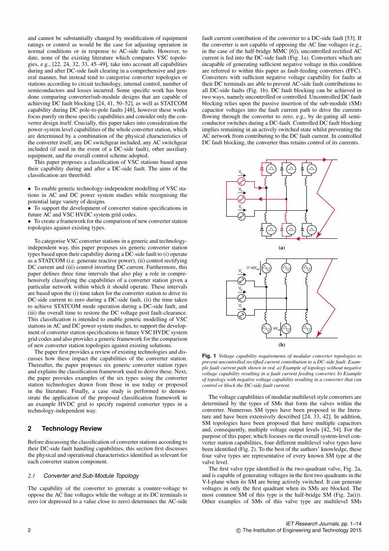
The capability of the converter to generate a counter-voltage tooppose the AC line voltages while the voltage at its DC terminals iszero (or depressed to a value close to zero) determines the AC-side
fault current contribution of the converter to a DC-side fault [53]. Ifthe converter is not capable of opposing the AC line voltages (e.g.,in the case of the half-bridge MMC [6]), uncontrolled rectified ACcurrent is fed into the DC-side fault (Fig. 1a). Converters which areincapable of generating sufficient negative voltage in this conditionare referred to within this paper as fault-feeding converters (FFC).Converters with sufficient negative voltage capability for faults attheir DC terminals are able to prevent AC-side fault contributions toall DC-side faults (Fig. 1b). DC fault blocking can be achieved intwo ways, namely uncontrolled or controlled. Uncontrolled DC faultblocking relies upon the passive insertion of the sub-module (SM)capacitor voltages into the fault current path to drive the currentsflowing through the converter to zero, e.g., by de-gating all semi-conductor switches during a DC-fault. Controlled DC fault blockingimplies remaining in an actively switched state whilst preventing theAC network from contributing to the DC fault current. In controlledDC fault blocking, the converter thus retains control of its currents.
VA
VB
VC
(a)
AB
ABVA
VB
VC
(b)
Fig. 1 Voltage capability requirements of modular converter topologies toprevent uncontrolled rectified current contribution to a DC-side fault. Exam-ple fault current path shown in red. a) Example of topology without negativevoltage capability resulting in a fault current feeding converter. b) Exampleof topology with negative voltage capability resulting in a converter that cancontrol or block the DC-side fault current.
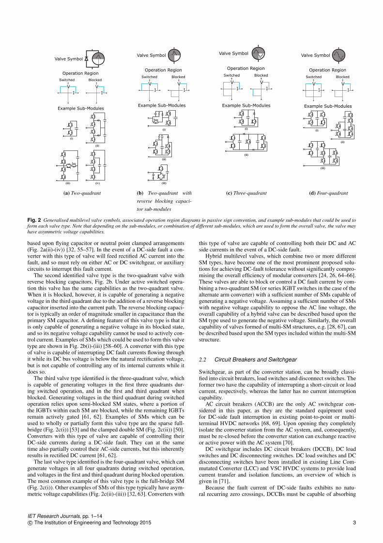
The voltage capabilities of modular multilevel style converters aredetermined by the types of SMs that form the valves within theconverter. Numerous SM types have been proposed in the litera-ture and have been extensively described [24, 33, 42]. In addition,SM topologies have been proposed that have multiple capacitorsand, consequently, multiple voltage output levels [42, 54]. For thepurpose of this paper, which focuses on the overall system-level con-verter station capabilities, four different multilevel valve types havebeen identified (Fig. 2). To the best of the authors’ knowledge, thesefour valve types are representative of every known SM type at thevalve level.
The first valve type identified is the two-quadrant valve, Fig. 2a,and is capable of generating voltages in the first two quadrants in theV-I-plane when its SM are being actively switched. It can generatevoltages in only the first quadrant when its SMs are blocked. Themost common SM of this type is the half-bridge SM (Fig. 2a(i)).Other examples of SMs of this valve type are multilevel SMs
IET Research Journals, pp. 1–142 c© The Institution of Engineering and Technology 2015
(i)
(iii)
(ii)
(iv)
V
I
V
I
Example Sub-Modules
(a) Two-quadrant
(i)
(ii)
(iii)
V
I
V
I
Example Sub-Modules
(b) Two-quadrant with
reverse blocking capaci-
tor sub-modules
(i)
(ii)
V
I
V
I
Valve Symbol
Operation Region
Switched Blocked
Example Sub-Modules
(c) Three-quadrant
(i)
(ii)
(iii)
V
I
V
I
Example Sub-Modules
(d) Four-quadrant
Fig. 2 Generalised multilevel valve symbols, associated operation region diagrams in passive sign convention, and example sub-modules that could be used toform each valve type. Note that depending on the sub-modules, or combination of different sub-modules, which are used to form the overall valve, the valve mayhave asymmetric voltage capabilities.
based upon flying capacitor or neutral point clamped arrangements(Fig. 2a(ii)-(iv)) [32, 55–57]. In the event of a DC-side fault a con-verter with this type of valve will feed rectified AC current into thefault, and so must rely on either AC or DC switchgear, or auxiliarycircuits to interrupt this fault current.
The second identified valve type is the two-quadrant valve withreverse blocking capacitors, Fig. 2b. Under active switched opera-tion this valve has the same capabilities as the two-quadrant valve.When it is blocked, however, it is capable of generating a negativevoltage in the third quadrant due to the addition of a reverse blockingcapacitor inserted into the current path. The reverse blocking capaci-tor is typically an order of magnitude smaller in capacitance than theprimary SM capacitor. A defining feature of this valve type is that itis only capable of generating a negative voltage in its blocked state,and so its negative voltage capability cannot be used to actively con-trol current. Examples of SMs which could be used to form this valvetype are shown in Fig. 2b(i)-(iii) [58–60]. A converter with this typeof valve is capable of interrupting DC fault currents flowing throughit while its DC bus voltage is below the natural rectification voltage,but is not capable of controlling any of its internal currents while itdoes so.
The third valve type identified is the three-quadrant valve, whichis capable of generating voltages in the first three quadrants dur-ing switched operation, and in the first and third quadrant whenblocked. Generating voltages in the third quadrant during switchedoperation relies upon semi-blocked SM states, where a portion ofthe IGBTs within each SM are blocked, while the remaining IGBTsremain actively gated [61, 62]. Examples of SMs which can beused to wholly or partially form this valve type are the sparse full-bridge (Fig. 2c(i)) [53] and the clamped double SM (Fig. 2c(ii)) [50].Converters with this type of valve are capable of controlling theirDC-side currents during a DC-side fault. They can at the sametime also partially control their AC-side currents, but this inherentlyresults in rectified DC current [61, 62].
The last valve type identified is the four-quadrant valve, which cangenerate voltages in all four quadrants during switched operation,and voltages in the first and third quadrant during blocked operation.The most common example of this valve type is the full-bridge SM(Fig. 2c(i)). Other examples of SMs of this type typically have asym-metric voltage capabilities (Fig. 2c(ii)-(iii)) [32, 63]. Converters with
this type of valve are capable of controlling both their DC and ACside currents in the event of a DC-side fault.
Hybrid multilevel valves, which combine two or more differentSM types, have become one of the most prominent proposed solu-tions for achieving DC-fault tolerance without significantly compro-mising the overall efficiency of modular converters [24, 26, 64–66].These valves are able to block or control a DC fault current by com-bining a two-quadrant SM (or series IGBT switches in the case of thealternate arm converter) with a sufficient number of SMs capable ofgenerating a negative voltage. Assuming a sufficient number of SMswith negative voltage capability to oppose the AC line voltage, theoverall capability of a hybrid valve can be described based upon theSM type used to generate the negative voltage. Similarly, the overallcapability of valves formed of multi-SM structures, e.g. [28, 67], canbe described based upon the SM types included within the multi-SMstructure.
2.2 Circuit Breakers and Switchgear
Switchgear, as part of the converter station, can be broadly classi-fied into circuit breakers, load switches and disconnect switches. Theformer two have the capability of interrupting a short-circuit or loadcurrent, respectively, whereas the latter has no current interruptioncapability.
AC circuit breakers (ACCB) are the only AC switchgear con-sidered in this paper, as they are the standard equipment usedfor DC-side fault interruption in existing point-to-point or multi-terminal HVDC networks [68, 69]. Upon opening they completelyisolate the converter station from the AC system, and, consequently,must be re-closed before the converter station can exchange reactiveor active power with the AC system [70].
DC switchgear includes DC circuit breakers (DCCB), DC loadswitches and DC disconnecting switches. DC load switches and DCdisconnecting switches have been installed in existing Line Com-mutated Converter (LCC) and VSC HVDC systems to provide loadcurrent transfer and isolation functions, an overview of which isgiven in [71].
Because the fault current of DC-side faults exhibits no natu-ral recurring zero crossings, DCCBs must be capable of absorbing
IET Research Journals, pp. 1–14c© The Institution of Engineering and Technology 2015 3
(a) Example topology with fault
current limiting
(b) Example topology without
fault current limiting
Fig. 3 Example DC circuit breaker topologies.
the stored energy within the circuit that is being isolated. There-fore, in practical realisations, the basic DCCB structure includes atminimum two parallel branches: a branch for load current and com-mutation, and a branch for energy absorption [34]. The load currentand commutation elements are responsible for carrying and inter-rupting load and fault currents, respectively. The energy absorptionbranch absorbs the energy stored in the circuit during interruption ofthe fault current.
Numerous DCCB topologies have been proposed to fulfil theneed of individually protecting transmission lines in future meshedHVDC grids, e.g. [34, 39, 72–74]. DCCBs can be distinguishedbased upon their ability (or inability) to operate in fault current lim-iting (FCL) mode. The FCL mode is achieved by active regulationof the impedance which the DCCB presents to the network. Withinknown topologies, active regulation can be achieved by DCCBswhich use modules of self-commutating switches in the commuta-tion branch, e.g. [36, 39, 75], Fig. 3a. Other known types of DCCBsdo not have FCL capability, e.g. [73, 76–78], Fig. 3b.
2.3 Auxiliary Circuits
Some converter topologies proposed in the literature include addi-tional auxiliary circuits which influence the response of the converterstation to a DC-side fault. Notable examples of such are the solutionsproposed in [40, 79], which use thyristor-based circuits to create alow impedance symmetrical fault on the AC side of the converterduring a DC-side fault, and the thyristor-based bypass circuit pre-sented in [80], which is used in conjunction with a fast DC-sidedisconnect switch during DC-side faults.
3 Converter Station Classification Framework
The power-system level capabilities of a converter station can bedivided into AC-side and DC-side capabilities. The requirementsfor AC-side capabilities have been well defined in various networkcodes, e.g. as done in the ENTSO-E Network Code on high-voltagedirect current connections [81]. The categories in [81] are (i) ActivePower Control and Frequency Support, (ii) Reactive Power Controland Voltage Support, (iii) Fault Ride Through, mainly for AC-side faults, (iv) Control requirements e.g., converter energization,system interactions, power oscillation damping, (v) Power SystemRestoration, mainly related to black-start of connected AC systems.Given the relatively recent appearance of the first multi-terminalDC networks, required power system-level capabilities at the DC-side are less documented. The capabilities at the DC-side could becategorized into active power control, DC voltage control, controlfor DC-side ancillary services and DC-side fault ride through andrestoration.
This paper proposes six types to categorise converter stationsaccording to their system-level characteristics, i.e. at both the AC-and DC-sides, during DC-side faults. The capabilities during andfollowing DC-side faults are the key aspect differentiating con-verter stations, and are therefore taken as the basis for the proposedclassification. Whilst there are numerous differences between con-verter station designs (e.g. converter topology, transformer wind-ing configuration, grounding system, switch-gear present, controlschemes), these design aspects do not result in fundamental dif-ferences from the system perspective during normal operation orfollowing AC-side disturbances.
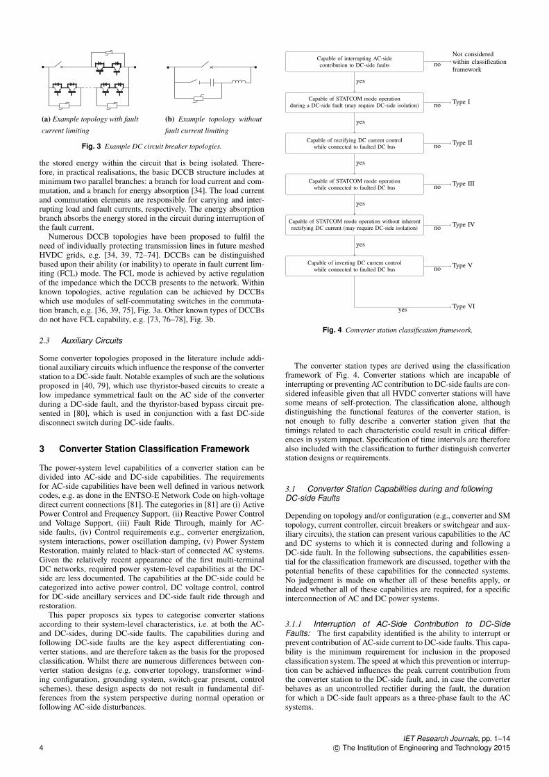
Capable of interrupting AC-sidecontribution to DC-side faults
Capable of STATCOM mode operationduring a DC-side fault (may require DC-side isolation)
Capable of rectifying DC current controlwhile connected to faulted DC bus
Capable of STATCOM mode operationwhile connected to faulted DC bus
Capable of STATCOM mode operation without inherentrectifying DC current (may require DC-side isolation)
Capable of inverting DC current controlwhile connected to faulted DC bus
Not consideredwithin classificationframework
Type I
Type II
Type III
Type IV
Type V
Type VI
no
no
no
no
no
no
yes
yes
yes
yes
yes
yes
Fig. 4 Converter station classification framework.
The converter station types are derived using the classificationframework of Fig. 4. Converter stations which are incapable ofinterrupting or preventing AC contribution to DC-side faults are con-sidered infeasible given that all HVDC converter stations will havesome means of self-protection. The classification alone, althoughdistinguishing the functional features of the converter station, isnot enough to fully describe a converter station given that thetimings related to each characteristic could result in critical differ-ences in system impact. Specification of time intervals are thereforealso included with the classification to further distinguish converterstation designs or requirements.
3.1 Converter Station Capabilities during and followingDC-side Faults
Depending on topology and/or configuration (e.g., converter and SMtopology, current controller, circuit breakers or switchgear and aux-iliary circuits), the station can present various capabilities to the ACand DC systems to which it is connected during and following aDC-side fault. In the following subsections, the capabilities essen-tial for the classification framework are discussed, together with thepotential benefits of these capabilities for the connected systems.No judgement is made on whether all of these benefits apply, orindeed whether all of these capabilities are required, for a specificinterconnection of AC and DC power systems.
3.1.1 Interruption of AC-Side Contribution to DC-SideFaults: The first capability identified is the ability to interrupt orprevent contribution of AC-side current to DC-side faults. This capa-bility is the minimum requirement for inclusion in the proposedclassification system. The speed at which this prevention or interrup-tion can be achieved influences the peak current contribution fromthe converter station to the DC-side fault, and, in case the converterbehaves as an uncontrolled rectifier during the fault, the durationfor which a DC-side fault appears as a three-phase fault to the ACsystems.
IET Research Journals, pp. 1–144 c© The Institution of Engineering and Technology 2015

3.1.2 STATCOM Mode Operation: The second identifiedcapability is the ability of a converter station to operate as a STAT-COM (i.e provide reactive power support) while the HVDC networkis faulted. This capability may have advantages in terms of increasedAC system voltage stability and control during the fault ride-throughprocess [82, 83], as well as allowing the converter stations to provideother ancillary services while there is a fault on the HVDC network,such as power system oscillation damping using reactive power mod-ulation [84, 85]. The precise form of converter topology will dictatewhether the ability to act as a STATCOM is temporarily interruptedduring the initial fault transient and whether STATCOM mode opera-tion may also have to be interrupted during post-fault recovery, if theconverter station is used post-fault to re-charge the HVDC network.
3.1.3 Rectifying DC Current Control Capability: The thirdidentified capability is the control of the DC-side current in the recti-fying direction during a DC-side fault. Two potential applications ofthe capability are identified here. First, the ability allows a converterstation to maintain a desired DC-side fault current level or to injecta pulse of current into the DC-side, which may be useful for faultlocation purposes, e.g., similar to the technique proposed in [86]for medium-voltage DC shipboard systems. Second, this capabilityis also associated with the ability to actively recharge the HVDCnetwork as part of the post-fault recovery [87], which otherwisemight require current limiting resistors or other auxiliary circuits andswitchgear. This capability can therefore be expected to significantlyinfluence the manner and speed in which post-fault restoration of theHVDC network can take place. Further discussions of this will begiven in Section 3.5.
3.1.4 Inverting DC Current Control Capability: The fourthidentified capability is the control of DC current in the invertingdirection during a DC-side fault. A potential application of this capa-bility is the active quenching of arcing faults, achieved by driving thepolarity of the DC system slightly negative when a DC-side fault isdetected [88–90].
3.2 Example Converter Station Topologies and SimulationResults
This section provides a detailed description of selected examples ineach of the proposed converter types, and simulation results for asubset of these to highlight their capabilities. The system and con-verter circuit parameters for the simulations are shown in Table 1,and a converter control scheme similar to the one presented in [91]is used. When converters with hybrid multilevel valves containingmore than one SM type are simulated, a 50:50 split of half-bridgeto other SMs is used. Typical interruption times for the switchgearassociated with a converter station are shown in Table 2, along withthe ones chosen for the simulation.
An AC system with a high short circuit ratio is used to showindicative peak DC-side fault current levels. For each result a lowimpedance pole-to-pole fault at the converter station terminals wasused. Pole-to-ground faults are not considered here, as, in asym-metric monopolar or bipolar configurations, similar results wouldbe obtained and in symmetric configurations, pole rebalancing fol-lowing the fault are not expected to require additional types in theclassification framework. A pole-to-ground fault results in a volt-age imbalance on the HVDC network, following which rebalancingwould be required before resuming normal operation. Pole rebalanc-ing involves either external equipment in form of a dynamic breakingsystem or can be added to the converter station design in the form ofa path for zero sequence currents and an associated controller [92].In the case of converters with fault blocking capability, the approachto deal with pole-to-ground faults does not result in the need foran additional type to differentiate its capabilities compared to thoseavailable with pole-to-pole faults [93].
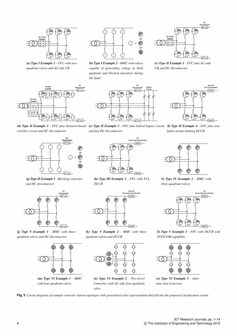
3.2.1 Type I: Examples of converter station topologies that fitwithin this type are FFCs, such as a half-bridge MMC (or MMCusing other two-quadrant valves) [6] or a two- or three-level con-verter [100], used in conjunction with ACCBs (Fig. 5a) [101].Another converter station topology which fits within type I is an
Table 1 Parameters of AC/DC system and converter stationused in simulation results
Parameter Value
Converter Rated Power 960 MWDC Voltage ±320 kVAC Primary Side Voltage (L-L RMS) 400 kVAC Converter Side Voltage (L-L RMS) 380 kVAC X/R Ratio 7AC Short Circuit Ratio 10Transformer Leakage Reactance 0.14 puArm Inductors 0.15 puNominal SM Voltage 7.28 kVNumber of SMs per Arm 93Equivalent Stored Energy 30.8 kJ/MVAOvercurrent Limit 2.25 kA
Table 2 Switchgear parameters used in simulation results
Technology Parameter Selected simu-lation value
AC circuit breaker Rated break time
SF6, air blast, oil 40 ∼ 60 ms 40 ms
DC circuit breaker Breaker opening time 3 ms
Passive resonant ≥ 20 ms [94, 95]Active resonant 5 ∼ 10 ms [76, 96]Hybrid 2 ∼ 3 ms [39, 72, 73]Power electronic ∼ few µs [97]
DC disconnect switch Opening time 2 ms
Ultra fast mechanical disconnect switch 2 ms [39, 98]High-speed switch (as disconnect switch) 2 ∼ 30 ms [99]
MMC that contains multilevel valves capable of generating voltagein the third quadrant (either of two-quadrant with reverse block-ing capacitors, or three- or four-quadrant) - Fig. 5b - in which theinterruption of the AC contribution to the DC-side fault is achievedby blocking the converter rather than using active current control.From a functionality perspective, the main distinction between thesetwo options is the time taken to interrupt the DC fault current. Forthe converter topologies that use three- or four-quadrant valves, thedefining feature that distinguishes the capabilities of the converteris the control scheme applied, with additional capabilities achiev-able if the converter is kept actively switching during the DC-sidefault. Two-quadrant valves with reverse blocking capacitors are notcapable of generating a negative voltage under actively switchedoperation, and so additional capabilities cannot be achieved.
Simulation results for both examples within this type are given inFig. 6a-b. For the example of an FFC with an ACCB the depressedvoltage at the converters’ DC-side results in the lower anti-paralleldiode in each SM conducting an uncontrolled fault current. The con-verter is unable to control its arm currents due to an inability to inserta negative arm voltage to oppose the AC line voltage. Before theACCB operates, the large current that flows from the AC-side intothe fault depresses the AC-side voltage and appears to the AC sys-tem as similar to a three-phase AC fault. Following the operation ofthe ACCB, the inductors within the fault current path (arm, DC-sideand line inductances) remain energised and cannot discharge instan-taneously, resulting in a sustained DC fault current. The dischargetime constant is inversely proportional to the resistance in the cur-rent path, and therefore the longest discharge is experienced duringa terminal fault, i.e., with the lowest resistance. The inductors mustdischarge before the fault is cleared, and in some cases the dischargecould take in the order of hundreds of milliseconds [102]. Methodshave been proposed to insert resistance into the arm to reduce thedischarge time [103], however a significantly quicker discharge isnot expected to be achievable without a large penalty in steady-statelosses and additional equipment.
Although the blocking converter example loses current controlimmediately after the inception of the DC-side fault, the DC faultcurrent is quickly limited due to the fast blocking action. In blockedmode, the three- or four-quadrant SMs output their nominal voltage,whereas the two-quadrant valve with reverse blocking capacitorsinserts its capacitors into the current path, each of which chargesuntil their total voltage supports the negative AC line voltage. The
IET Research Journals, pp. 1–14c© The Institution of Engineering and Technology 2015 5
AC Circuit
Breaker
(a) Type I Example 1 - FFC with two-
quadrant valves and AC-side CB
=
or
or
(b) Type I Example 2 - MMC with valves
capable of generating voltage in third
quadrant and blocked operation during
DC fault
AC Circuit
Breaker
DC
Disconnector
(c) Type II Example 1 - FFC plus AC-side
CB and DC disconnector
AC-Side
Crowbar
Parallel
Crowbar
DC
Disconnector
(d) Type II Example 2 - FFC plus thyristor-based
crowbar circuit and DC disconnector
DC
Disconnector Bypass
Circuit
(e) Type II Example 3 - FFC plus hybrid bypass circuit
and fast DC disconnector
Non-FCL
DC Circuit Breaker
DCCB
DCCB
(f) Type II Example 4 - FFC plus non-
fault-current-limiting DCCB
=
or
DC
Disconnector
or
(g) Type II Example 5 - Blocking converter
and DC disconnector
FCL
Power Electronic Breaker
DCCB
DCCB
(h) Type III Example 1 - FFC with FCL
DCCB
(i) Type IV Example 1 - MMC with
three-quadrant valves
DC
Disconnector
(j) Type V Example 1 - MMC with three-
quadrant valves and DC disconnector
Non-FCL
Power Electronic Breaker
DCCB
DCCB
(k) Type V Example 2 - MMC with three-
quadrant valves and DCCB
FCL
Power Electronic Breaker
DCCB
DCCB
(l) Type V Example 3 - FFC with DCCB with
STATCOM capability
(m) Type VI Example 1 - MMC
with four-quadrant valves
(n) Type VI Example 2 - Two-Level
Converter with AC-side four-quadrant
valve
(o) Type VI Example 3 - Alter-
nate Arm Converter
Fig. 5 Circuit diagrams of example converter station topologies with generalised valve representation that fall into the proposed classification system.
IET Research Journals, pp. 1–146 c© The Institution of Engineering and Technology 2015

Fault Current Duration & Capability Availability
0 0.05 0.1 0.15 0.2 0.25 0.3 0.35 0.4
Time (s)
-10
0
10
(kA
)
PCC Phase Currents
-500
0
500
(kV
)
PCC Line Voltages
-10
-5
0
(kA
)
DC Current
0
500
1000
(kV
)
DC Pole Voltages
Converter Side
Grid Side
(a) Type I Example 1
Fault Current Duration & Capability Availability
0 0.05 0.1 0.15 0.2 0.25 0.3 0.35 0.4
Time (s)
-10
0
10
(kA
)
PCC Phase Currents
-500
0
500
(kV
)
PCC Line Voltages
-10
-5
0
(kA
)
DC Current
0
500
1000
(kV
)
DC Pole Voltages
Converter Side
Grid Side
(b) Type I Example 2
Fault Current Duration & Capability Availability
0 0.05 0.1 0.15 0.2 0.25 0.3 0.35 0.4
Time (s)
-10
0
10
(kA
)
PCC Phase Currents
-500
0
500
(kV
)
PCC Line Voltages
-10
-5
0
(kA
)
DC Current
0
500
1000
(kV
)
DC Pole Voltages
Converter Side
Grid Side
(c) Type II Example 2
Fault Current Duration & Capability Availability
0 0.05 0.1 0.15 0.2 0.25 0.3 0.35 0.4
Time (s)
-10
0
10
(kA
)
PCC Phase Currents
-500
0
500
(kV
)
PCC Line Voltages-15
-10
-5
0
(kA
)
DC Current
0
500
1000
(kV
)
DC Pole Voltages
Converter Side
Grid Side
(d) Type II Example 3
Fault Current Duration & Capability Availability
0 0.05 0.1 0.15 0.2 0.25 0.3 0.35 0.4
Time (s)
-5
0
5
(kA
)
PCC Phase Currents
-500
0
500
(kV
)
PCC Line Voltages
-4
-2
0
(kA
)
DC Current
0
500
1000
(kV
)
DC Pole Voltages
Converter Side
Grid Side
(e) Type II Example 4
Fault Current Duration & Capability Availability
0 0.05 0.1 0.15 0.2 0.25 0.3 0.35 0.4
Time (s)
-5
0
5
(kA
)
PCC Phase Currents
-500
0
500
(kV
)
PCC Line Voltages
-4
-2
0
2
(kA
)
DC Current
0
500
1000
(kV
)
DC Pole Voltages
Converter Side
Grid Side
(f) Type III Example 1
Fault Current Duration & Capability Availability
0 0.05 0.1 0.15 0.2 0.25 0.3 0.35 0.4
Time (s)
-5
0
5
(kA
)
PCC Phase Currents
-500
0
500
(kV
)
PCC Line Voltages
-4
-2
0
2
(kA
)
DC Current
0
500
1000
(kV
)
DC Pole Voltages
Converter Side
Grid Side
(g) Type IV Example 1
Fault Current Duration & Capability Availability
0 0.05 0.1 0.15 0.2 0.25 0.3 0.35 0.4
Time (s)
-5
0
5
(kA
)
PCC Phase Currents
-500
0
500
(kV
)
PCC Line Voltages
-4
-2
0
2
(kA
)
DC Current
0
500
1000
(kV
)
DC Pole Voltages
Converter Side
Grid Side
(h) Type V Example 1
Fault Current Duration & Capability Availability
0 0.05 0.1 0.15 0.2 0.25 0.3 0.35 0.4
Time (s)
-2
0
2
(kA
)
PCC Phase Currents
-500
0
500
(kV
)
PCC Line Voltages-6-4-202
(kA
)
DC Current
0
500
1000
(kV
)
DC Pole Voltages
Converter Side
Grid Side
(i) Type V Example 2
Fault Current Duration & Capability Availability
0 0.05 0.1 0.15 0.2 0.25 0.3 0.35 0.4
Time (s)
-5
0
5
(kA
)
PCC Phase Currents
-500
0
500
(kV
)
PCC Line Voltages
-4
-2
0
2
(kA
)
DC Current
0
500
1000
(kV
)
DC Pole Voltages
Converter Side
Grid Side
(j) Type V Example 3
Fault Current Duration & Capability Availability
0 0.05 0.1 0.15 0.2 0.25 0.3 0.35 0.4
Time (s)
-5
0
5
(kA
)
PCC Phase Currents
-500
0
500
(kV
)
PCC Line Voltages
-4
-2
0
2
(kA
)
DC Current
0
500
1000
(kV
)
DC Pole Voltages
Converter Side
Grid Side
(k) Type VI Example 1 (l) Fault Duration & Capability Legend
Fig. 6 Simulation results illustrating the response and functionalities of example converter station topologies from each class. Sub-figure labels correspond tothe converter station topologies given in Fig. 5.
IET Research Journals, pp. 1–14c© The Institution of Engineering and Technology 2015 7

blocking of the SMs therefore results in a counter-voltage beingimposed which drives the current flowing through the converter armsto zero.
3.2.2 Type II: Five example converter station designs which fallinto the Type II classification are shown in Fig. 5c-g. The first exam-ple converter station (Fig. 5c) uses an FFC in conjunction with anACCB to interrupt the AC-side contribution to the DC-side fault[70]. A DC disconnector is used to first isolate the converter’s DCterminals from the external grid, before the ACCB can be re-closedand the converter de-blocked, enabling it to move into STATCOMmode. The second example (Fig. 5d) uses an FFC in conjunctionwith an additional thyristor based crowbar circuit and DC discon-nector. During a DC-side fault the crowbar circuit is used to form alow impedance AC-side fault [40, 79], which interrupts the AC-sidecontribution to the DC-fault, resulting in the DC-side fault currentdecaying. Thereafter, the DC disconnector can be used to isolate theconverter’s DC terminals from the faulted grid, allowing the con-verter to de-block and move into STATCOM mode. The crowbarcircuit can be placed on the AC-side of the converter, or in parallelwith the converter SMs. The third example (Fig. 5e) uses a thyris-tor based bypass bridge to divert the AC-side fault current out ofthe main converter during a DC-side fault [80]. A DC disconnec-tor is then used to isolate the converters DC terminals under zerocurrent conditions. Once this is achieved the thyristor circuit can bede-gated, resulting in the DC fault current being interrupted oncethe thyristor bridge is commutated by the AC voltage. The fourthexample converter station (Fig. 5f) uses an FFC in conjunction witha DCCB, which is not capable of current limiting [104]. The DCCBis relied upon to interrupt the DC-side fault current and isolate theconverter’s DC terminals. Depending on the speed with which theDCCB opens, the converter may or may not require blocking in orderto protect its semiconductors. In the event that the converter blocks, itmust be de-blocked before moving into STATCOM mode. The finalexample (Fig. 5g) uses a blocking converter in conjunction with aDC disconnector. When a DC-side fault is detected, the converteris blocked, thereby driving all currents within the converter towardszero. The DC disconnector can then isolate, under zero current con-ditions, the converter’s DC terminals from the faulted grid, allowingthe converter to be de-blocked and moved into STATCOM operation.
Simulation results from three of the example converters stationtopologies are shown in Fig. 6c-e. In each of the example simula-tions the converter initially loses current control following a DC-sidefault, with subsequent blocking of the converter and uncontrolledrectification of AC current. Once the converter has been isolatedfrom the faulted external grid the converter can be de-blocked, andthe DC voltage at the converter’s DC terminals re-established, afterwhich STATCOM operation is possible. Re-charge of the DC net-work using this type of converter station is expected to requirepre-insertion resistors due to an inability to control the DC-sidecurrents into a low voltage DC-side. The cases of the FFC withACCB and DC disconnector, and the blocking converter with DCdisconnector are omitted as the results are similar to those shownin Fig. 6a-b, but with a subsequent de-blocking and move intoSTATCOM mode.
Simulation results for the FFC with AC crowbar and DC discon-nector, are given in Fig. 6c. Once the DC-side fault is detected thethyristors are fired, creating a low impedance symmetrical AC faultwhich interrupts the AC-side contribution to the DC-side fault cur-rent. The latter decays to zero in a similar fashion as the type I FFCwith AC CBs. The fault is isolated using DC disconnectors after thecurrent has decayed to a level below their residual current capability.The DC voltage is restored in an uncontrolled manner after isolationof the fault, followed by a de-blocking of the converter and moveinto STATCOM mode.
The FFC with hybrid bypass and fast DC disconnector reducesthe fault interruption time compared with the FFC and FFC withAC crowbar and DC disconnector (Fig. 6d). In this case, the con-verter initially loses current control and blocks itself, moving intonatural rectification mode, after which the thyristor bypass branchfor each converter arm is activated. Since the bypass branch presentsa lower impedance compared with the converter arms, the current
is naturally commutated from the latter to the former, thereby driv-ing the current flowing through the converter arms to zero withina cycle. This provides zero current conditions for the DC discon-nector located between the converter and the DC connection pointof the bypass circuit when isolating the converter from the DC net-work. Thereafter, the firing signals for the thyristor bypass circuitcan be stopped, which results in the DC fault current being extin-guished approximately half a cycle after the DC disconnector hasopened. Once this has occurred the converters controller can be de-blocked and the converter can operate in STATCOM mode after theDC voltage at the converters terminals has been restored.
In the case of the FFC with non-fault-current-limiting DCCB,shown in Fig. 6e, the converter initially loses current control. TheDC fault is interrupted by the DCCB, which allows the converterto de-block and move into STATCOM mode. In the case shown theconverter blocks itself during the fault, however as discussed in thesection above this may not be the case depending on the speed of theDCCB.
3.2.3 Type III: An example of a converter station that meets theclassification of Type III is a FFC (e.g. MMC with two-quadrantvalve) with a FCL power electronic circuit breaker, shown in Fig. 5h.This converter station uses the FCL functionality of the power elec-tronic circuit breaker to limit the DC-side fault current. During aDC-side fault an uncontrolled fault current is initially conductedthrough the converter, before the power electronic circuit breakerstarts fault current limitation and eventually isolates the fault. Oncethe DC-side current is zero, the converter station can deblock andprovide reactive power to the AC system. When the fault has beencleared (by an external device or by itself in the case of a temporaryfault) the converter station can recharge the network. In either case,the power electronic circuit breaker is used in FCL mode during therecharge process.
Simulation results of this example topology are given in Fig. 6f.The converter station is unable to provide reactive power to the ACsystem while its DC terminals are faulted, but is capable of con-trolling rectifying DC current. A fault occurs at 0.1 s, after whichthere is a limited DC-side overcurrent. The hybrid circuit breakeroperates in 3 ms and limits the DC-side fault current to 3 kA. Dur-ing fault current limiting, the converter is blocked. After 60 ms, acontrol decision is made to isolate the fault and the DC current isreduced to zero. After this point, the converter can begin switching,with capability to source or sink reactive power.
3.2.4 Type IV: A converter station with the functionalities ofthis type is achieved if a three-quadrant valve, as discussed inSection 2.1, is used in an MMC operated without the use of any aux-iliary equipment at the DC or AC side (Fig. 5i). The inability of threequadrant valves to generate voltage in the fourth quadrant impliesthat, during a DC-side fault, all current flowing through the valves ofthe converter must be in a rectifying direction. Consequently, activefault current level control in rectifying mode and active rechargeof the DC network from zero DC voltage can be achieved. STAT-COM mode operation may also be achieved by mapping the ACcurrents in an upwards direction through each valve, as discussedin [61, 62]. This control mode, however, results in a DC current alsobeing injected into the faulted DC network.
In the example simulation (Fig. 6g), the converter is able toquickly interrupt the DC fault current, and provides STATCOM(with inherent rectifying DC current) and rectifying DC currentcontrol capabilities during the full fault clearing process, with theexception of the milliseconds immediately after fault inception. Inthe example, the converters controllers reduce the DC current tozero at t = 0.012 s. Within the time interval of [0.225,0.325] ms,the STATCOM mode operation is accompanied by a DC currentcirculating between the arms and the fault. After t = 0.34, the con-verter injects DC rectifying current while the reactive AC currentcomponent has been set to zero.
3.2.5 Type V: Examples of converter station topologies that fallinto Type V are a three-quadrant converter with either DC discon-nectors or DCCBs (Fig. 5j-k), or an FFC used in conjunction withan FCL DCCB (Fig. 5l). In the latter case, coordinated control is
IET Research Journals, pp. 1–148 c© The Institution of Engineering and Technology 2015

needed to allow the converter to remain actively switching while theDCCB is in FCL mode. Unlike Type IV converter station topolo-gies, the examples of this type based on the three-quadrant topologyare able to provide STATCOM mode operation without inherent rec-tifying DC current if they are isolated by the DC disconnectors orDCCBs. STATCOM mode operation during a DC-side fault prior tothis operation results in inherent rectifying DC current. The exam-ple topology that uses an FFC in conjunction with an FCL DCCBachieves STATCOM capability without rectifying DC current beforeisolation. The FCL capability is used to limit the DC fault currentto a safe level, as well as keeping the DC voltage at the converter’sterminals above the natural rectification voltage, which allows theconverter to remain de-blocked, and capable of providing continuousSTATCOM mode operation during the DC-side fault.
Simulation results from the three examples of Type V are shownin Fig. 6h-j. The examples of the MMC with three-quadrant valvesquickly reduce the DC fault current, before the DC disconnectoror DCCBs isolate the converter from the faulted DC bus (Fig. 6hand 6i). Within the interval [0.1,0.2] s, the three-quadrant convert-ers inject reactive current with associated rectifying DC current. Att=0.2 s, the DC disconnector or DCCBs isolate the converter fromthe faulted DC bus, after which the DC voltage at the converter sta-tion terminal re-establishes. The main difference between using DCdisconnector and DCCBs is whether the MMC with three-quadrantvalves needs to reduce the current to zero or not. Since the DC dis-connectors do not have interrupting capability, the DC current has tobe driven to zero by the three-quadrant converter. The converter isable to provide STATCOM mode without a rectifying current feed-ing to the DC bus once the DC disconnector or DCCBs isolates theconverter from the faulted DC bus.
The FFC example provides the same current control capabilitiesas the MMC with three-quadrant valves, whereas in this case the DCvoltage is kept around the nominal value by the FCL action of theDCCB (Fig. 6j). The FFC converter is temporarily blocked duringthe initial stage of the DC-side fault due to overcurrent, then de-blocked approximately 0.6 ms after the fault instant when the DCcurrent has been limited to a low level by the FCL operation of theDCCBs. After de-blocking, the converter is operated in STATCOMmode and the DC current is controlled at 0.5 pu by the FCL opera-tion of the DCCBs. STATCOM mode operation while connecting tothe faulted DC bus is demonstrated until 0.2 s, then the DCCBs areordered to open. The converter blocking action can be expected todepend on the breaker opening time, the overcurrent protection levelof the converter and the rate of collapse of the DC bus voltage. Inthis simulation, the breaker opening time and the overcurrent protec-tion setting is 2 ms and 1.6 pu, respectively, and the DC bus voltagecollapses immediately after the inception of the DC-side fault. Thetemporary blocking of the converter in the example results couldpotentially be avoided by co-designing the DCCB and converter.
3.2.6 Type VI: Three converter station design examples whichachieve the Type VI classification are the MMC with four-quadrantvalves, a two-level converter with AC-side four quadrant valves[105], or the alternate arm converter (Fig. 5m-o) [26, 27]. Each ofthese station designs is capable of remaining in active switched oper-ation during a DC-side fault (i.e., the converter is not blocked, oris temporarily blocked and then de-blocked) and retaining currentcontrol over their AC-side, DC-side and internal currents, meaningSTATCOM mode operation as well as control over both DC currentin the rectifying and inverting operation is possible.
Simulation results for the MMC with four-quadrant valve exam-ple are shown in Fig. 6k. The DC-side fault causes a transient initialincrease of DC current. The magnitude and duration of this initialincrease will be influenced by the response of the current controllerto the DC voltage collapse caused by the fault [106]. Current controlis re-established shortly and the DC current is then driven to zero.Once the DC fault current is suppressed the ability of the converterto control DC current in both the rectifying and inverting directionsis shown, STATCOM mode operation is also demonstrated.
3.3 Time Intervals
To comprehensively specify the response of a converter station dur-ing and after DC-side faults, three time intervals are defined inaddition to the types. The first time interval is the fault current inter-ruption time, which describes the time interval from the inception ofthe fault (or alternatively the arrival of the fault wave at the converterstation) to the instant at which the DC fault current at the converterstation terminals has reached a value at which it can be assumedextinct (i.e., close to zero). The second time interval, known as theSTATCOM mode operation time, describes the interval from faultcurrent interruption until the converter station is able to operate as aSTATCOM without any restrictions imposed by the circuit or faultclearing equipment. The third time interval is the DC voltage restora-tion time, which describes the time interval from the clearance ofthe DC-side fault (after which voltage restoration can be initiated)to the instant at which the voltage is restored to the value at whichpower flow can be resumed. The terms in the following sections aregeneralised and not all terms apply to all converter stations, i.e.,some terms can be neglected depending on classification type andtechnology used.
3.3.1 Fault Current Interruption Time: The fault current inter-ruption time ∆tint is the time between the onset of fault currentincrease at the converter DC terminals (tf) and fault current inter-ruption (tint). It is the sum of the fault detection time ∆td, openingtime ∆to and DC-side fault current decay time ∆tdec:
∆tint = tint − tf
= ∆td + ∆to + ∆tdec(1)
The fault detection time ∆td is the time between the onset of faultcurrent increase at the converter DC terminals and fault detection,which thus excludes the time it takes for the fault to propagate tothe converter terminals. Depending on the technology used for inter-rupting the DC-side fault, ∆to refers to either the opening time ofthe ACCB, the opening time of the DCCB or the response time ofthe converter fault current control.
3.3.2 STATCOM Mode Operation Time: The STATCOMmode operation time ∆tQ→Q* is the sum of the time intervals ofthe actions following fault current interruption required for the con-verter station to be capable of tracking a reactive power set-pointQ∗. This time is the sum of the converter station DC isolation time∆tDC
isolate, AC reconnection time ∆tACconnect, converter deblocking time
∆tconvdeblock, and converter control action time ∆tconv
Q :
∆tQ→Q* = tQ* − tint
= ∆tDCisolate + ∆tAC
connect + ∆tconvdeblock + ∆tconv
Q(2)
Depending on the technology used to interrupt a DC-side fault orto provide converter station isolation from the DC side, certain timeintervals might not apply (i.e., delay equal to zero). In certain con-verter station types STATCOM mode operation may not be possibleat all, or STATCOM mode operation during a DC-side fault alwaysresults in inherent rectifying DC current (Type IV converter stations,and some Type V converter stations before the converter station isisolated from the DC network).
3.3.3 DC Voltage Restoration Time: The DC voltage restora-tion time ∆tVDC → V∗
DCis the sum of the time intervals of the actions
following fault clearance (tflt,DCclear ) required for the converter station
to restore the DC network to its nominal voltage level, assumingthe DC voltage has completely collapsed. This time is the sum ofthe time taken for the converter to reconnect to the network (if dis-connected) ∆tconnect,DC, the time taken for the network to passivelycharge through the converter ∆trecharge,passive, and the time taken forthe converter to actively charge the network to its nominal set-point∆trecharge,active:
IET Research Journals, pp. 1–14c© The Institution of Engineering and Technology 2015 9
∆tVDC → V∗DC
= tV∗DC
− tflt,DCclear
= ∆tconnect,DC + ∆trecharge,passive + ∆trecharge,active(3)
Depending on the classification type and technology used, one orboth of ∆tconnect,DC and ∆trecharge,passive may be zero as the con-verter station may remain connected to the fault network throughoutthe fault and the converter station may capable of actively recharg-ing the network without a passive stage. Further discussion of this isgiven in Section 3.5.
3.4 Syntax for Presentation of Types and Time Intervals
To support future grid code specification and development, andfor ease of comparison between converter station designs, acommon syntax for presentation of the type and time inter-vals associated with a certain converter station is proposed:“X(∆tint/∆tQ→ Q∗/∆tVDC → V∗
DC)”, where X represents the
converter station type and the time intervals are specified in mil-liseconds, considering worst case scenarios (i.e fault instance occur-ring on point of wave that maximises time taken to interrupt DCfault current). The proposed common syntax serves to describe thecharacteristics of an existing or prospective converter station in aparticular location in an AC/DC system. For example, a type I con-verter station with ∆tint = 300 ms, ∆tQ→Q* not being applicable,and ∆tVDC → V∗
DC= 80 ms, would be described as I(300/− /80).
A converter station can then be proposed or selected for use ina particular location according to the requirements on both typeand time intervals specified for converter stations used at that loca-tion. For instance, a requirement for II(600/100/300) would befulfilled by a II(100/50/100) converter station, and also by aV I(600/100/300) converter station.
3.5 Post-fault Network Recharging Sequences
Following fault clearance, the HVDC network may require recharg-ing before resuming normal operation. Recharging the network froma high-voltage source (i.e. the AC network) requires a sequence ofstages to limit the inrush current, which would otherwise damagethe converter components. These stages depend on the topology ofthe converter station that is required to perform the recharging. Theycan be broadly defined by the converter station action during therecharge, i.e., passive or active, in which the recharging current islimited by passive components or is actively controlled by the con-verter, respectively. In these simulation cases, the converter stationin question is the only device recharging the HVDC network.
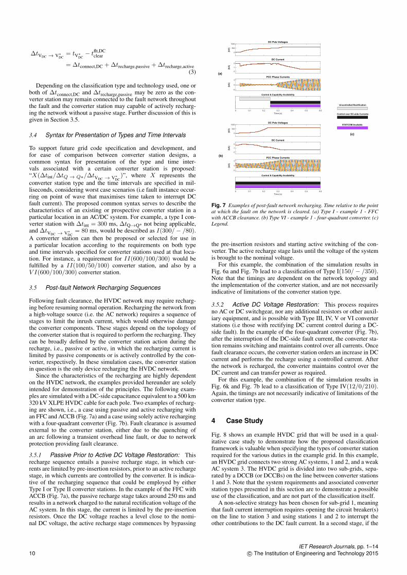
Since the characteristics of the recharging are highly dependenton the HVDC network, the examples provided hereunder are solelyintended for demonstration of the principles. The following exam-ples are simulated with a DC-side capacitance equivalent to a 500 km320 kV XLPE HVDC cable for each pole. Two examples of recharg-ing are shown, i.e., a case using passive and active recharging withan FFC and ACCB (Fig. 7a) and a case using solely active rechargingwith a four-quadrant converter (Fig. 7b). Fault clearance is assumedexternal to the converter station, either due to the quenching ofan arc following a transient overhead line fault, or due to networkprotection providing fault clearance.
3.5.1 Passive Prior to Active DC Voltage Restoration: Thisrecharge sequence entails a passive recharge stage, in which cur-rents are limited by pre-insertion resistors, prior to an active rechargestage, in which currents are controlled by the converter. It is indica-tive of the recharging sequence that could be employed by eitherType I or Type II converter stations. In the example of the FFC withACCB (Fig. 7a), the passive recharge stage takes around 250 ms andresults in a network charged to the natural rectification voltage of theAC system. In this stage, the current is limited by the pre-insertionresistors. Once the DC voltage reaches a level close to the nomi-nal DC voltage, the active recharge stage commences by bypassing
Control & Capability Availability
0 0.1 0.2 0.3 0.4 0.5 0.6
Time (s)
-2
0
2
(kA
)
PCC Phase Currents
-2
-1
0
(kA
)
DC Current
0
500
1000
(kV
)
DC Pole Voltages
Control & Capability Availability
0 0.1 0.2 0.3 0.4 0.5 0.6
Time (s)
-2
0
2
(kA
)
PCC Phase Currents
-2
-1
0
(kA
)
DC Current
0
500
1000
(kV
)
DC Pole Voltages
Uncontrolled Rectification
Control over DC-side Currents
STATCOM Available
(a)
(b)
(c)
Fig. 7 Examples of post-fault network recharging. Time relative to the pointat which the fault on the network is cleared. (a) Type I - example 1 - FFCwith ACCB clearance. (b) Type VI - example 1 - four-quadrant converter. (c)Legend.
the pre-insertion resistors and starting active switching of the con-verter. The active recharge stage lasts until the voltage of the systemis brought to the nominal voltage.
For this example, the combination of the simulation results inFig. 6a and Fig. 7b lead to a classification of Type I(150/− /350).Note that the timings are dependent on the network topology andthe implementation of the converter station, and are not necessarilyindicative of limitations of the converter station type.
3.5.2 Active DC Voltage Restoration: This process requiresno AC or DC switchgear, nor any additional resistors or other auxil-iary equipment, and is possible with Type III, IV, V or VI converterstations (i.e those with rectifying DC current control during a DC-side fault). In the example of the four-quadrant converter (Fig. 7b),after the interruption of the DC-side fault current, the converter sta-tion remains switching and maintains control over all currents. Oncefault clearance occurs, the converter station orders an increase in DCcurrent and performs the recharge using a controlled current. Afterthe network is recharged, the converter maintains control over theDC current and can transfer power as required.
For this example, the combination of the simulation results inFig. 6k and Fig. 7b lead to a classification of Type IV(12/0/210).Again, the timings are not necessarily indicative of limitations of theconverter station type.
4 Case Study
Fig. 8 shows an example HVDC grid that will be used in a qual-itative case study to demonstrate how the proposed classificationframework is valuable when specifying the types of converter stationrequired for the various duties in the example grid. In this example,an HVDC grid connects two strong AC systems, 1 and 2, and a weakAC system 3. The HVDC grid is divided into two sub-grids, sepa-rated by a DCCB (or DCCBs) on the line between converter stations1 and 3. Note that the system requirements and associated converterstation types presented in this section are to demonstrate a possibleuse of the classification, and are not part of the classification itself.
A non-selective strategy has been chosen for sub-grid 1, meaningthat fault current interruption requires opening the circuit breaker(s)on the line to station 3 and using stations 1 and 2 to interrupt theother contributions to the DC fault current. In a second stage, if the
IET Research Journals, pp. 1–1410 c© The Institution of Engineering and Technology 2015

AC System 1 AC System 2
Wind Farm 1
Wind Farm 2
AC System 3
Sub-Grid 1
Sub-Grid 2
Station 1 Station 2
Station 5
Station 4Station 3
OHL
Fig. 8 Example HVDC grid.
Type IType II
Type IIIType IVType V
Type VI
R1 R2 R3 R4Not fulfilledFulfilled
Requirements
Fig. 9 Example of mapping of power system requirements and convertertypes, excluding timing requirements.
fault is found to be permanent, isolation of the fault is achieved usingdisconnect switches (without current interruption capability) on thefaulted line. If the fault is found to be non-permanent (plausible onan overhead line), converter stations 1 and 2 quickly restore the DCvoltage (and power flow) after a prescribed de-ionisation time. Afully selective strategy has been specified for sub-grid 2. This meansthat DCCBs are installed at the ends of every cable and no specialactions are required by the converters.
We assume the system operators of the AC and HVDC grids havedetermined various requirements for system operation based on theirextensive system studies. Four candidate requirements that might beapplied have been identified:
R1 - DC current interruption: DC currents must be interruptedby a specified time which may be based on either avoiding highpeak DC currents or avoiding pro-longed DC tail currents due touncontrolled discharge of passive elements.R2 - Active discharge and polarity inversion: fault currents mustbe controlled to improve DC-side fault detection and arc extinguish-ing. This requirement is fulfilled when the converter station is ableto discharge the line under both rectifying and inverting conditions.R3 - Support for weak AC grid: the converter must be able todeliver reactive power while the DC network is faulted. This require-ment is fulfilled when reactive power is delivered by a specified timeand without simultaneous injection of DC current.R4 - Controlled DC black start: the converter must be able torestore the DC voltage in a controlled manner to allow for severalrestoration attempts in quick succession.
The mapping of the converter types and these requirements(excluding timings) is given in Fig. 9, and provides a framework fora structured approach to the selection of the required type for eachstation in the example HVDC grid. The mapping shows which typesare ruled out when certain requirements are to be met. In a furtherstage, when timings are added to the requirements, some of the con-verter stations belonging to a certain type may also be ruled out. Thisdemonstrates the usefulness of both the converter types and timingsused within the classification framework.
In the example case study, station 1 needs to have fast inter-ruption which may be aided by the ability to control fault currentthrough inverting action that extracts energy from the transmissionline which would otherwise flow toward the fault. Further, fast black
Table 3 Candidate converter types for case study, excluding timing requirements
Converter Requirements Candidate converters type
1 {R1,R2,R4} VI2 {R1,R4} III-IV-V-VI3 {R3} II-III-V-VI4 {} I-II-III-IV-V-VI5 {} I-II-III-IV-V-VI
start enables a fast recovery after non-permanent faults of the OHL.Station 1 thus has the requirements set {R1,R2,R4} and, as Fig. 9shows, only Type VI stations can meet this set of requirements.This is recorded in the first line of Table 3. Assuming that for thisexample, Station 2 is not required to invert, the set of requirementsdrops to {R1,R4} and the minimally required converter station typeis reduced to Type III. In sub-grid 2, given that the stations are notrequired to perform any protective functions, Station 4 and Station 5may be of Type I or higher. In this sub-grid, Station 3 is connectedto the weak AC system 3 and so the requirement R3 is applied. Asa consequence, Type II or higher stations, excluding Type IV due toits inherent injection of DC current, could be considered.
It might be that the required features of the converter station (andhence the required converter station type) may not all come froma strict a priori specification, but may expanded or refined through astudy of stability criteria of the overall system. These studies may setthe required timings for each of the converter stations, determined asvalues of ∆tint, ∆tQ→ Q∗ and ∆tVDC → V∗
DC. These timings, along
with a requirement for a minimum converter station type, could thenform the basis of a grid code specification which is not set out interms of specific technologies and therefore does not preclude futureconverter or breaker technologies. The interactions between requiredtimings and interoperability between different converter types couldalso be explored. For example a grid code operator could discoverthat the overall requirements for system stability are met by eithera minimum of I(10/-/100) or a II(30/50/100) converter stations. Itis then up to the system operator(s) to decide on the converter sta-tion types depending on system stability criteria and other desiredfeatures that take account of future grid expansions.
5 Discussion
The classification methodology uses the capabilities during andafter a DC-side fault as a main differentiating factor among con-verter stations. This choice is demonstrated using simulations ofselected example converter stations, which confirm that, apart fromthe time intervals, the converter stations of the same type are ableto provide the same capabilities. An overview of example converterstation topologies within each type, given in Table 5, demonstratesthe merit of the proposed classification; it is the first classificationframework which categorises existing and potential future converterstation designs according to capabilities rather than technology, andencompasses a wide range of potential converter station designs.
Table 4 Converter Station Classification
Capable of:Type
I II III IV V VI
Interrupting AC-side contribution to DC-side faults 3 3 3 3 3 3
STATCOM mode operation during DC-side fault
(may require DC-side isolation)7 3 3 3 3 3
Rectifying DC current control while connected to
faulted DC network7 3 3 3 3
STATCOM mode operation while connected to
faulted DC network7 3 3 3
STATCOM mode operation without inherent recti-
fying DC current (may require DC-side isolation)7 3 3
Inverting DC current control while connected to
faulted DC network7 3
IET Research Journals, pp. 1–14c© The Institution of Engineering and Technology 2015 11

Table 5 Example Converter Stations
Type Examples
I Fault Feeding Converter (FFC) (e.g., MMC with two-quadrant valves or two-/three-
level converter) with AC circuit breaker
Blocking converter (i.e., MMC or other modular converter with valves capable of
generating a negative voltage with blocked operation during DC-side fault)
II FFC with AC circuit breaker and DC disconnector
FFC with hybrid bypass and DC disconnector
FFC with AC-side crowbar and DC switch
FFC with non-fault current limiting DC circuit breaker
Blocking converter with DC disconnector
III FFC with fault current limiting DC circuit breaker without active DC-side fault ride
through control
IV MMC with three-quadrant valve and active control during fault
V MMC with three-quadrant valve and DC disconnector
FFC with fault current limiting DC circuit breaker and active DC-side fault ride through
control
MMC with three-quadrant valve and DC circuit breaker
VI MMC with four-quadrant valves (e.g., full-bridge SMs)
Two-Level converter with AC-side cascaded full-bridge SMs
Alternate arm converter
One of the main aims of the proposed classification system isto enable technology-independent AC/DC system studies, as illus-trated in Fig. 10. Performing studies in this manner would allow asystem operator to focus on technical requirements, and investigatethe interaction between the capabilities different converter stationscould give (included in the classification of the converter types), andthe subsequent impact of these capabilities on the stability of theoverall power system (as specified by the required timings).
AC Grid 1
AC Grid 2
Wind Farm 1
Wind Farm 2
V(10/50/100)
VI(5/10/50)
I(20/-/100)
I(25/-/200)
Fig. 10 Generic system study utilising the proposed classification system.
6 Conclusion
This paper provides a classification framework that enables VSCHVDC converter station designs to be categorised into six types,which differentiate converter stations based on system-level capabil-ities (ability to operate as a STATCOM, ability to control rectifyingDC current, and ability to control inverting DC current) rather thantechnology. The classification framework and examples of con-verter station designs that fall into each proposed type within theframework are summarised in Table 4. The six converter types areextended with three time intervals to fully characterise the converterstation from a capability point-of-view. To describe a converter sta-tion or a requirement for a converter station, a common syntax is pro-posed in the following format: X(∆tint/∆tQ→ Q∗/∆tVDC → V∗
DC)
ms, where X represents the converter station type, ∆tint representsthe time interval taken to interrupt any DC fault current flowingthrough the converter station, ∆tQ→ Q∗ represents the time inter-val taken to track a reactive power set-point, and ∆tVDC → V∗
DCis the time interval taken to restore a fully discharged HVDC net-work post-fault clearance. We anticipate such a categorisation willprove useful for: (i) Fair and meaningful comparison of new con-verter station designs, comprising of converter topologies, control,
circuit breakers and auxiliary equipment. (ii) Specification of gridcodes for the future power system, thereby enabling a multi-vendormarket of suppliers. (iii) Enabling technology-independent AC/DCsystem studies. Future work could focus on system studies usingthe proposed classification system, as well as the development oftechnology-independent converter station models based upon theclassification.
7 References[1] P. Bresesti, W. L. Kling, R. L. Hendriks, and R. Vailati: ‘HVDC Connection
of Offshore Wind Farms to the Transmission System’, IEEE Trans. EnergyConvers., 2007, 22, (1), pp. 37–43.
[2] N. M. Kirby, L. Xu, M. Luckett, and W. Siepmann: ‘HVDC transmission forlarge offshore wind farms’, Power Engineering Journal, 2002, 16, (3), pp. 135–141.
[3] A. E. MacDonald, C. T. M. Clack, A. Alexander, A. Dunbar, J. Wilczak, andY. Xie: ‘Future cost-competitive electricity systems and their impact on us co2emissions’, Nature Climate Change, 2016, 6, pp. 526 EP –, article. [Online].Available: https://doi.org/10.1038/nclimate2921
[4] N. Flourentzou, V. G. Agelidis, and G. D. Demetriades: ‘VSC-Based HVDCPower Transmission Systems: An Overview’, IEEE Trans. Power Electron.,2009, 24, (3), pp. 592–602.
[5] D. Van Hertem, O. Gomis-Bellmunt, and J. Liang: ‘HVDC Grids:For Off-shore and Supergrid of the Future’. Wiley-IEEE Press, 2016).
[6] A. Lesnicar and R. Marquardt: ‘An innovative modular multilevel convertertopology suitable for a wide power range’, in Proc. Power Tech ConferenceProceedings, 2003 IEEE Bologna, 3, Jun. 2003, p. 6 pp.
[7] R. Marquardt: ‘Modular Multilevel Converter: An universal concept for HVDC-Networks and extended DC-Bus-applications’, in Proc. Power ElectronicsConference (IPEC), 2010 International, Jun. 2010, pp. 502–507.
[8] T. Xu, M. W. Donoghue, and C. C. Davidson: ‘IGBT overcurrent turn-off testsfor the MMC-based VSC valves’, in Proc. 2013 15th European Conference onPower Electronics and Applications (EPE), Sep. 2013, pp. 1–10.
[9] C. Oates: ‘Modular multilevel converter design for VSC HVDC applications’,IEEE Trans. Emerg. Sel. Topics Power Electron., 2015, 3, (2), pp. 505–515.
[10] L. Feng, R. Gou, X. Yang, X. Sun, and F. Zhuo: ‘Design of high power den-sity sub module in modular multilevel converter for VSC-HVDC project’,in Proc. 10th International Conference on Advances in Power System Control,Operation Management (APSCOM 2015), Nov. 2015, pp. 1–6.
[11] H. Chen, W. Coo, Z. Tan, P. Bordignon, R. Yi, and H. Zhang: ‘Hardware designand key submodule testing of the world’s first single-level press-pack igbt basedmodular multilevel converter for VSC HVDC’, in Proc. 8th IET InternationalConference on Power Electronics, Machines and Drives (PEMD 2016), Apr.2016, pp. 1–6.
[12] M. Spence, A. Plumpton, C. Rout, A. Millington, and R. Keyse: ‘Design andCharacterisation of Optimised Protective Thyristors for VSC Systems’, in Proc.PCIM Europe 2016; International Exhibition and Conference for Power Elec-tronics, Intelligent Motion, Renewable Energy and Energy Management, May2016, pp. 1–8.
[13] J. Chivite-Zabalza, J. Perrier, M. Boden, T. Xu, and J. Outram: ‘Development ofa Full-Bridge Sub-Module for HVDC and STATCOM Markets’, in Proc. PCIMEurope 2017; International Exhibition and Conference for Power Electronics,Intelligent Motion, Renewable Energy and Energy Management, May 2017, pp.1–7.
[14] L. Wang, G. Cheng, T. Bureau, X. Li, D. Zhang, and Y. Fan: ‘Automa-tion and control design of overvoltage protection for sub-modules in modularmultilevel converter’, in Proc. 2017 IEEE 2nd Information Technology, Net-working, Electronic and Automation Control Conference (ITNEC), Dec. 2017,pp. 1048–1052.
[15] M. Hagiwara and H. Akagi: ‘Control and Experiment of Pulsewidth-ModulatedModular Multilevel Converters’, IEEE Trans. Power Electron., 24, (7), pp.1737–1746.
[16] M. Hagiwara, R. Maeda, and H. Akagi: ‘Control and Analysis of the ModularMultilevel Cascade Converter Based on Double-Star Chopper-Cells (MMCC-DSCC)’, IEEE Trans. Power Electron., 26, (6), pp. 1649–1658.
[17] B. S. Riar and U. K. Madawala: ‘Decoupled Control of Modular MultilevelConverters Using Voltage Correcting Modules’, IEEE Trans. Power Electron.,30, (2), pp. 690–698.
[18] S. Fan, K. Zhang, J. Xiong, and Y. Xue: ‘An Improved Control System forModular Multilevel Converters with New Modulation Strategy and VoltageBalancing Control’, IEEE Trans. Power Electron., 30, (1), pp. 358–371.
[19] K. Ilves, A. Antonopoulos, S. Norrga, and H. P. Nee: ‘Steady-State Analysisof Interaction Between Harmonic Components of Arm and Line Quantities ofModular Multilevel Converters’, IEEE Trans. Power Electron., 27, (1), pp. 57–68.
[20] K. Ilves, S. Norrga, L. Harnefors, and H. P. Nee: ‘On Energy Storage Require-ments in Modular Multilevel Converters’, IEEE Trans. Power Electron., 29, (1),pp. 77–88.
[21] M. M. C. Merlin, T. C. Green, P. D. Mitcheson, F. J. Moreno, K. J. Dyke,and D. R. Trainer: ‘Cell capacitor sizing in modular multilevel converters andhybrid topologies’, in Proc. European Conference On Power Electronics andApplications (EPE’14-ECCE Europe), Aug. 2014, pp. 1–10.
[22] H. Akagi: ‘Classification, Terminology, and Application of the Modular Multi-level Cascade Converter (MMCC)’, IEEE Trans. Power Electron., 26, (11), pp.3119–3130.
IET Research Journals, pp. 1–1412 c© The Institution of Engineering and Technology 2015

[23] M. A. Perez, S. Bernet, J. Rodriguez, S. Kouro, and R. Lizana: ‘Circuit Topolo-gies, Modeling, Control Schemes, and Applications of Modular MultilevelConverters’, IEEE Trans. Power Electron., 30, (1), pp. 4–17.
[24] J. Qin, M. Saeedifard, A. Rockhill, and R. Zhou: ‘Hybrid Design of Modu-lar Multilevel Converters for HVDC Systems Based on Various SubmoduleCircuits’, IEEE Trans. Power Del., 2015, 30, (1), pp. 385–394.
[25] G. P. Adam, S. J. Finney, and B. W. Williams: ‘Hybrid converter with acside cascaded H-bridge cells against H-bridge alternative arm modular mul-tilevel converter: Steady-state and dynamic performance’, IET Generation,Transmission Distribution, 2013, 7, (3), pp. 318–328.
[26] M. M. C. Merlin, D. Soto-Sanchez, P. D. Judge et al.: ‘The Extended OverlapAlternate Arm Converter: A Voltage-Source Converter With DC Fault Ride-Through Capability and a Compact Design’, IEEE Trans. Power Electron.,2018, 33, (5), pp. 3898–3910.
[27] M. M. C. Merlin, T. C. Green, P. D. Mitcheson et al.: ‘The Alternate ArmConverter: A New Hybrid Multilevel Converter With DC-Fault BlockingCapability’, IEEE Trans. Power Del., 2014, 29, (1), pp. 310–317.
[28] P. D. Judge, M. M. C. Merlin, T. C. Green, D. R. Trainer, and K. Ver-shinin: ‘Thyristor-Bypassed Sub-Module Power-Groups for Achieving High-Efficiency, DC Fault Tolerant Multilevel VSCs’, IEEE Trans. Power Del., 2017,PP, (99), pp. 1–1.
[29] H. Rao: ‘Architecture of Nan’ao multi-terminal VSC-HVDC system and itsmulti-functional control’, CSEE Journal of Power and Energy Systems, 2015,1, (1), pp. 9–18.
[30] ‘Zhoushan five-terminal VSC-HVDC Project’, http://www.nrec.com/en/case/-449.html.
[31] ‘SGRI Participates in Construction of Zhang-Bei DC Grid Pilot Project_PressRelease_C-EPRI’, http://www.cepri.com.cn/release/details_66_745.html.
[32] A. Nami, J. Liang, F. Dijkhuizen, and G. D. Demetriades: ‘Modular Mul-tilevel Converters for HVDC Applications: Review on Converter Cells andFunctionalities’, IEEE Trans. Power Electron., 2015, 30, (1), pp. 18–36.
[33] M. A. Perez, S. Bernet, J. Rodriguez, S. Kouro, and R. Lizana: ‘Circuit Topolo-gies, Modeling, Control Schemes, and Applications of Modular MultilevelConverters’, IEEE Trans. Power Electron., 2015, 30, (1), pp. 4–17.
[34] C. M. Franck: ‘HVDC Circuit Breakers: A Review Identifying Future ResearchNeeds’, IEEE Trans. Power Del., 2011, 26, (2), pp. 998–1007.
[35] O. Cwikowski, B. Chang, M. Barnes, R. Shuttleworth, and A. Beddard: ‘Faultcurrent testing envelopes for VSC HVDC circuit breakers’, TransmissionDistribution IET Generation, 2016, 10, (6), pp. 1393–1400.
[36] D. Keshavarzi, E. Farjah, and t. ghanbari: ‘A Hybrid DC Circuit Breakerand Fault Current Limiter with Optional Interruption Capability’, IEEE Trans.Power Electron., 2017, 33, (99), pp. 1–1.
[37] G. Liu, F. Xu, Z. Xu, Z. Zhang, and G. Tang: ‘Assembly HVDC Breakerfor HVDC Grids With Modular Multilevel Converters’, IEEE Trans. PowerElectron., 2017, 32, (2), pp. 931–941.
[38] R. Sander, M. Suriyah, and T. Leibfried: ‘Characterization of a CountercurrentInjection-Based HVDC Circuit Breaker’, IEEE Trans. Power Electron., 33, (4),pp. 2948–2956.
[39] J. Häfner and B. Jacobson: ‘Proactive Hybrid HVDC Breakers-A key innovationfor reliable HVDC grids’, Proc. of Cigré Bologna, Paper, 2011, 264.
[40] X. Li, Q. Song, W. Liu, H. Rao, S. Xu, and L. Li: ‘Protection of NonpermanentFaults on DC Overhead Lines in MMC-Based HVDC Systems’, IEEE Trans.Power Del., 2013, 28, (1), pp. 483–490.
[41] S. Cui, S. Kim, J. J. Jung, and S. K. Sul: ‘Principle, control and comparison ofmodular multilevel converters (MMCs) with DC short circuit fault ride-throughcapability’, in Proc. 2014 IEEE Applied Power Electronics Conference andExposition - APEC 2014, Mar. 2014, pp. 610–616.
[42] L. Huang, X. Yang, P. Xu et al.: ‘The evolution and variation of sub-moduletopologies with DC-fault current clearing capability in MMC-HVDC’, in Proc.2017 IEEE 3rd International Future Energy Electronics Conference and ECCEAsia (IFEEC 2017 - ECCE Asia), Jun. 2017, pp. 1938–1943.
[43] M. Abedrabbo, M. Wang, P. Tielens et al.: ‘Impact of DC grid contingencies onAC system stability’, in Proc. 13th IET International Conference on AC and DCPower Transmission (ACDC 2017), Feb. 2017, pp. 1–7.
[44] A. Ellis, Y. Kazachkov, E. Muljadi, P. Pourbeik, and J. J. Sanchez-Gasca:‘Description and technical specifications for generic wtg models: A statusreport’, in Proc. 2011 IEEE/PES Power Systems Conference and Exposition,March 2011, pp. 1–8.
[45] S. Debnath, J. Qin, B. Bahrani, M. Saeedifard, and P. Barbosa: ‘Operation, Con-trol, and Applications of the Modular Multilevel Converter: A Review’, IEEETrans. Power Electron., 30, (1), pp. 37–53.
[46] J. Hu, R. Zeng, and Z. He: ‘DC fault ride-through of MMCs for HVDC systems:A review’, The Journal of Engineering, 2016, 1, (1).
[47] L. Zhang, Y. Zou, J. Yu et al.: ‘Modeling, control, and protection of modu-lar multilevel converter-based multi-terminal hvdc systems: A review’, CSEEJournal of Power and Energy Systems, 2017, 3, (4), pp. 340–352.
[48] T. H. Nguyen, K. A. Hosani, M. S. E. Moursi, and F. Blaabjerg: ‘An overview ofmodular multilevel converters in HVDC transmission systems with STATCOMoperation during pole-to-pole dc short circuits’, IEEE Trans. Power Electron.,2019, 34, (5), pp. 4137–4160.
[49] M. N. Raju, J. Sreedevi, R. P Mandi, and K. S. Meera: ‘Modular multilevel con-verters technology: a comprehensive study on its topologies, modelling, controland applications’, IET Power Electronics, 2019, 12, (2), pp. 149–169.
[50] R. Marquardt: ‘Modular Multilevel Converter topologies with DC-Short circuitcurrent limitation’, in Proc. Power Electronics and ECCE Asia (ICPE ECCE),2011 IEEE 8th International Conference On, May 2011, pp. 1425–1431.
[51] J. Zhang and C. Zhao: ‘The research of sm topology with dc fault tolerance inmmc-hvdc’, IEEE Trans. Power Del., 2015, 30, (3), pp. 1561–1568.
[52] A. Nami, J. Liang, F. Dijkhuizen, and P. Lundberg: ‘Analysis of modular mul-tilevel converters with dc short circuit fault blocking capability in bipolar hvdctransmission systems’, in Proc. 2015 17th European Conference on PowerElectronics and Applications (EPE’15 ECCE-Europe), Sep. 2015, pp. 1–10.
[53] R. Li, J. E. Fletcher, L. Xu, D. Holliday, and B. W. Williams: ‘A Hybrid Mod-ular Multilevel Converter With Novel Three-Level Cells for DC Fault BlockingCapability’, IEEE Trans. Power Del., 2015, 30, (4), pp. 2017–2026.
[54] V. Dargahi, A. K. Sadigh, M. Abarzadeh, S. Eskandari, and K. A. Corzine:‘A New Family of Modular Multilevel Converter Based on Modified Flying-Capacitor Multicell Converters’, IEEE Trans. Power Electron., 30, (1), pp. 138–147.
[55] T. A. Meynard and H. Foch: ‘Multi-level conversion: High voltage choppersand voltage-source inverters’, in Proc. , 23rd Annual IEEE Power ElectronicsSpecialists Conference, 1992. PESC ’92 Record, Jun. 1992, pp. 397–403 vol.1.
[56] T. B. Soeiro and J. W. Kolar: ‘Novel 3-level Hybrid Neutral-Point-ClampedConverter’, in Proc. IECON 2011 - 37th Annual Conference of the IEEEIndustrial Electronics Society, Nov. 2011, pp. 4457–4462.
[57] E. Solas, G. Abad, J. A. Barrena, S. Aurtenetxea, A. Cárcar, and L. Zajac: ‘Mod-ular Multilevel Converter With Different Submodule Concepts Part I: CapacitorVoltage Balancing Method’, IEEE Trans. Ind. Electron., 2013, 60, (10), pp.4525–4535.
[58] X. Yang, Y. Xue, B. Chen, Z. Lin, T. Q. Zheng, and Y. Li: ‘Novel modularmultilevel converter against DC faults for HVDC applications’, CSEE Journalof Power and Energy Systems, 2017, 3, (2), pp. 140–149.
[59] X. Yang, Y. Xue, B. Chen et al.: ‘Reverse blocking sub-module based modularmultilevel converter with DC fault ride-through capability’, in Proc. 2016 IEEEEnergy Conversion Congress and Exposition (ECCE), Sep. 2016, pp. 1–7.
[60] H. Kim, J. Kang, S. Kim, C. K. Kim, and K. Hur: ‘DC fault protection formodular multilevel converter HVDC using asymmetrical unipolar full-bridgesubmodule’, in Proc. 2015 9th International Conference on Power Electronicsand ECCE Asia (ICPE-ECCE Asia), Jun. 2015, pp. 1083–1089.
[61] X. Yu, Y. Wei, and Q. Jiang: ‘STATCOM Operation Scheme of the CDSM-MMC During a Pole-to-Pole DC Fault’, IEEE Trans. Power Del., 2016, 31, (3),pp. 1150–1159.
[62] X. Yu, Y. Wei, and Q. Jiang: ‘New submodule circuits for modular multilevelcurrent source converters with DC fault ride through capability’, in Proc. 2016IEEE Applied Power Electronics Conference and Exposition (APEC), Mar.2016, pp. 1468–1474.
[63] K. Ilves, L. Bessegato, L. Harnefors, S. Norrga, and H. P. Nee: ‘Semi-full-bridgesubmodule for modular multilevel converters’, in Proc. 2015 9th InternationalConference on Power Electronics and ECCE Asia (ICPE-ECCE Asia), Jun.2015, pp. 1067–1074.
[64] M. M. C. Merlin, T. C. Green, P. D. Mitcheson, D. R. Trainer, D. R. Critch-ley, and R. W. Crookes: ‘A new hybrid multi-level Voltage-Source Converterwith DC fault blocking capability’, in Proc. AC and DC Power Transmission(ACDC). IET International Conference On, 2010, pp. 1–5.
[65] P. D. Judge, G. Chaffey, M. M. C. Merlin, P. R. Clemow, and T. C. Green:‘Dimensioning and Modulation Index Selection for the Hybrid Modular Multi-level Converter’, IEEE Trans. Power Electron., 2018, 33, (5), pp. 3837–3851.
[66] M. Lu, Q. Zhou, J. Hu, N. Wang, and M. Xiang: ‘On hybrid modular multi-level converters with active DC fault ride-through capability’, in Proc. 12th IETInternational Conference on AC and DC Power Transmission (ACDC 2016),May 2016, pp. 1–6.
[67] P. D. Judge, M. M. C. Merlin, T. Green, D. R. Trainer, and K. Vershinin:‘Thyristor/diode-bypassed sub-module power-groups for improved efficiencyin modular multilevel converters’, IEEE Trans. Power Del., 2018, pp. 1–1.
[68] Working group B4.37, ‘VSC Transmission’, 269, (().[69] P. Haugland, ‘It’s time to connect: Technical description of hvdc light R©
technology’, 2008.[70] A. Hassanpoor, Y. Häfner, A. Nami, and K. Vinothkumar: ‘Cost-effective solu-
tions for handling dc faults in VSC HVDC transmission’, in Proc. 2016 18thEuropean Conference on Power Electronics and Applications (EPE’16 ECCEEurope), Sep. 2016, pp. 1–7.
[71] Cigré Joint Working Group A3-B4.34: ‘Technical Requirements and Specifica-tions of State-of-the-art HVDC Switching Equipment’.
[72] B. Yang, D. Cao, W. Shi, W. LV, W. Wang, and B. Liu: ‘A novel commutation-based hybrid HVDC circuit breaker’, in Proc. Proc. Cigré 2017 Canada,Winnipeg, Canada, 30 Sep. - 6 Oct. 2017.
[73] W. Grieshaber, D. Dupraz, J.P.and Penache, and L. Violleau: ‘Development andtest of a 120 kV direct current circuit breaker’, Paris, France, 24 – 29 Aug. 2014.
[74] L. Ängquist, S. Norrga, T. Modeer, and S. Nee: ‘Fast HVDC breaker usingreduced-rating power electronics’, in Proc. Proc. IET ACDC 2017, Manchester,UK, 14.
[75] F. Dijkhuizen and B. Berggren: ‘Zoning in high voltage DC (HVDC) grids usinghybrid DC breaker’, in Proc. Proc. EPRI HVDC and FACTS Conf., Palo Alto,USA, 2013, pp. 1–8.
[76] K. Tahata, S. Ka, S. Tokoyoda et al.: ‘HVDC circuit breakers for HVDC gridapplications’, in Proc. Proc. Cigré AORC Technical Meeting, Tokyo, Japan,2014.
[77] Y. Wang and R. Marquardt: ‘Future hvdc-grids employing modular multilevelconverters and hybrid dc-breakers’, in Proc. 2013 15th European Conference onPower Electronics and Applications (EPE), Sept 2013.
[78] B. Xiang, L. Zhang, K. Yang et al.: ‘Arcing Time of a DC Circuit BreakerBased on a Superconducting Current-Limiting Technology’, IEEE Trans. Appl.Supercond., 2016, 26, (7), pp. 1–5.
[79] A. A. Elserougi, A. S. Abdel-Khalik, A. M. Massoud, and S. Ahmed: ‘A NewProtection Scheme for HVDC Converters Against DC-Side Faults With CurrentSuppression Capability’, IEEE Trans. Power Del., 2014, 29, (4), pp. 1569–1577.
IET Research Journals, pp. 1–14c© The Institution of Engineering and Technology 2015 13

[80] I. A. Gowaid: ‘A Low-Loss Hybrid Bypass for DC Fault Protection of ModularMultilevel Converters’, IEEE Trans. Power Del., 2017, 32, (2), pp. 599–608.
[81] ENTSO-E, European Commission: ‘Establishing a network code on require-ments for grid connection of high voltage direct current systems and directcurrent connected power park modules’, 2015.
[82] H. G. Sarmiento, G. Pampin, and J. D. de Leon: ‘Feasibility Studies forDynamic VAR and STATCOM Applications to Prevent a Fast Voltage Col-lapse’, in Proc. IEEE/PES Transmission and Distribution Conference, May2006, pp. 1420–1425.
[83] B. Singh, R. Saha, A. Chandra, and K. Al-Haddad: ‘Static synchronous com-pensators (STATCOM): A review’, IET Power Electronics, 2009, 2, (4), pp.297–324.
[84] E. N. Lerch, D. Povh, and L. Xu: ‘Advanced SVC control for damping powersystem oscillations’, IEEE Trans. Power Syst., 1991, 6, (2), pp. 524–535.
[85] S. Johansson, G. Asplund, E. Jansson, and R. Rudervall: ‘Power system stabilitybenefits with VSC DC-transmission systems’, in Proc. CIGRE conference, Apr.2004, pp. 1–8.
[86] Q. Deng, X. Liu, R. Soman, M. Steurer, and R. A. Dougal: ‘Primary and backupprotection for fault current limited mvdc shipboard power systems’, in Proc.2015 IEEE Electric Ship Technologies Symposium (ESTS), June 2015, pp. 40–47.
[87] G. Chaffey and T. C. Green: ‘Low speed protection methodology for a symmet-rical monopolar HVDC network’, in Proc. 13th IET International Conferenceon AC and DC Power Transmission (ACDC 2017), Feb. 2017, pp. 1–6.
[88] D. Jovcic, W. Lin, S. Nguefeu, and H. Saad: ‘Full bridge MMC converter con-troller for HVDC operation in normal and DC fault conditions’, in Proc. 2017International Symposium on Power Electronics (Ee), pp. 1–6.
[89] Siemens, ‘HVDC PLUS – the Decisive Step Ahead’).[90] J. Dorn, P. L. Seta, F. Schettler et al.: ‘Full-bridge VSC: An essential enabler
of the transition to an energy system dominated by renewable sources’, in Proc.2016 IEEE Power and Energy Society General Meeting (PESGM), Jul. 2016,pp. 1–5.
[91] P. Münch, D. Görges, M. Izák, and S. Liu: ‘Integrated current control, energycontrol and energy balancing of Modular Multilevel Converters’, in Proc.IECON 2010 - 36th Annual Conference on IEEE Industrial Electronics Society,Nov. 2010, pp. 150–155.
[92] M. Wang, W. Leterme, G. Chaffey, J. Beerten, and D. Van Hertem: ‘Pole Rebal-ancing Methods for Pole-to-ground Faults in Symmetrical Monopolar HVDCGrids’, IEEE Trans. Power Del., 2018, early online access
[93] R. Dantas, J. Liang, A. Adamczyk, C. Barker, and R. Whitehouse: ‘ProtectionStrategy for Multi-terminal DC Networks with Fault Current Blocking Capabil-ity of Converters’, in Proc. Proc. IET ACDC 2017, Manchester, UK, 14–16 Feb.2017.
[94] B. Pauli, G. Mauthe, E. Ruoss, G. Ecklin, J. Porter, and J. Vithayathil: ‘Develop-ment of a high current HVDC circuit breaker with fast fault clearing capability’,IEEE Trans. Power Del., 1988, 3, (4), pp. 2072–2080.
[95] C. Peng, J. Wen, X. Wang, Z. Liu, and K. Yu: ‘Development of DC TransferSwitch for Ultra High Voltage DC Transmission Systems’, Proceedings of theChinese Society for Electrical Engineering (CSEE), 2012, 32, (16), pp. 151–156.
[96] T. Eriksson, M. Backman, and S. Halén: ‘A low loss mechanical HVDC breakerfor HVDC grid applications’, in Proc. Proc. Cigré Paris, Paris, France, 24.
[97] J. Magnusson, R. Saers, L. Liljestrand, and G. Engdahl: ‘Separation of theEnergy Absorption and Overvoltage Protection in Solid-State Breakers by theUse of Parallel Varistors’, IEEE Trans. Power Electron., 2014, 29, (6), pp.2715–2722.
[98] P. Skarby and U. Steiger: ‘An ultra-fast disconnecting switch for a hybrid HVDCbreaker - a technical breakthrough’, in Proc. Cigré 2013 Canada Conf., Calgary,Alberta, Canada, 9.
[99] C. Petino, M. Heidemann, D. Eichhoff, M. Stumpe, E. Spahic, and F. Schet-tler: ‘Application of multilevel full bridge converters in HVDC multiterminalsystems’, IET Power Electronics, 2016, 9, (2), pp. 297–304.
[100] G. Asplund, K. Eriksson, and K. Svensson: ‘Dc transmission based on voltagesource converters’, in Proc. Proc. CIGRÉ SC14 Colloquium, South Africa, 29-30 Sep. 1997.
[101] WG B4.37: ‘Technical Brochure 269: VSC Transmission’. CIGRE, 2005).[102] R. Dantas, J. Liang, C. E. Ugalde-Loo, A. Adamczyk, C. Barker, and R. White-
house: ‘Progressive fault isolation and grid restoration strategy for mtdcnetworks’, IEEE Trans. on Power Del., 2018, 33, (2), pp. 909–918.
[103] J. Chongxue, Lu Yu, Wang Nannan, Wang Hui, Wang Jiacheng, and Zhao Xicai:‘Comparative Analysis of DC Line Fault Recovery Technology in VSC HVDC’,in Proc. CIGRE SC A3, B4 and D1 Colloquium, Winnipeg, Canada, Oct. 2017,p. 13 pages.
[104] D. S. Loume, A. Bertinato, B. Raison, and B. Luscan: ‘A multi-vendor protec-tion strategy for HVDC grids based on low-speed DC circuit breakers’, in Proc.Proc. IET ACDC 2017, Manchester, UK, 14–16 Feb. 2017.
[105] G. P. Adam, S. J. Finney, and B. W. Williams: ‘Hybrid converter with ac sidecascaded h-bridge cells against h-bridge alternative arm modular multilevel con-verter: steady-state and dynamic performance’, IET Generation, TransmissionDistribution, 2013.
[106] M. Winkelnkemper, L. Schwager, P. Blaszczyk, M. Steurer, and D. Soto: ‘Shortcircuit output protection of MMC in voltage source control mode’, in Proc. 2016IEEE Energy Conversion Congress and Exposition (ECCE), pp. 1–6.
IET Research Journals, pp. 1–1414 c© The Institution of Engineering and Technology 2015
View publication statsView publication stats