Power Supplies and System Cooling
42
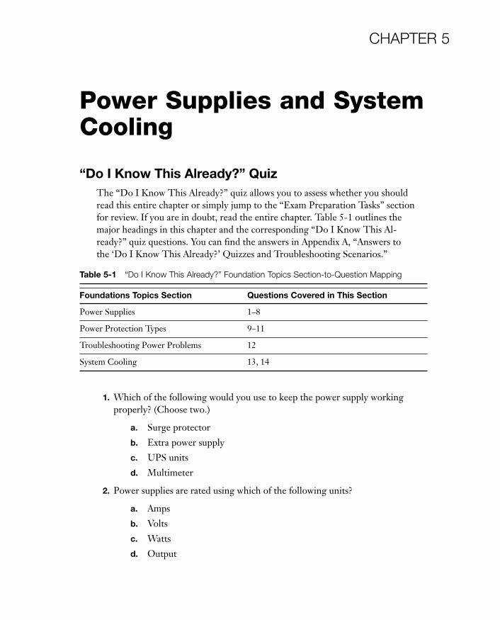
CHAPTER 5 Power Supplies and System Cooling “Do I Know This Already?” Quiz The “Do I Know This Already?” quiz allows you to assess whether you should read this entire chapter or simply jump to the “Exam Preparation Tasks” section for review. If you are in doubt, read the entire chapter. Table 5-1outlines the major headings in this chapter and the corresponding “Do I Know This Al- ready?” quiz questions. You can find the answers in Appendix A, “Answers to the ‘Do I Know This Already?’ Quizzes and Troubleshooting Scenarios.” 1. Which of the following would you use to keep the power supply working properly? (Choose two.) a. Surge protector b. Extra power supply c. UPS units d. Multimeter 2. Power supplies are rated using which of the following units? a. Amps b. Volts c. Watts d. Output Table 5-1 “Do I Know This Already?” Foundation Topics Section-to-Question Mapping Foundations Topics Section Questions Covered in This Section Power Supplies 1–8 Power Protection Types 9–11 Troubleshooting Power Problems 12 System Cooling 13, 14
Transcript of Power Supplies and System Cooling
CHAPTER 5
Power Supplies and SystemCooling
“Do I Know This Already?” QuizThe “Do I Know This Already?” quiz allows you to assess whether you shouldread this entire chapter or simply jump to the “Exam Preparation Tasks” sectionfor review. If you are in doubt, read the entire chapter. Table 5-1 outlines themajor headings in this chapter and the corresponding “Do I Know This Al-ready?” quiz questions. You can find the answers in Appendix A, “Answers tothe ‘Do I Know This Already?’ Quizzes and Troubleshooting Scenarios.”
1. Which of the following would you use to keep the power supply workingproperly? (Choose two.)
a. Surge protector
b. Extra power supply
c. UPS units
d. Multimeter
2. Power supplies are rated using which of the following units?
a. Amps
b. Volts
c. Watts
d. Output
Table 5-1 “Do I Know This Already?” Foundation Topics Section-to-Question Mapping
Foundations Topics Section Questions Covered in This Section
Power Supplies 1–8
Power Protection Types 9–11
Troubleshooting Power Problems 12
System Cooling 13, 14
05_9780789740472_ch05.qxd 9/23/09 3:07 PM Page 157
158 CompTIA A+ Cert Guide
3. Newer computers’ power supplies typically have which of the following poweroutput ratings?
a. 300 watts
b. 400 watts
c. 250 watts
d. 500 watts or higher
4. Most power supplies in use today are designed to handle which two voltageranges? (Choose two.)
a. 115
b. 300
c. 230
d. 450
5. Which of the following are causes of power supply overheating?
a. Overloading the power supply
b. Fan failure
c. Dirt or dust
d. All of these options are correct
6. How many pins are used for the main power connection by recent ATX/BTXmotherboards with ATX12V 2.2 power supplies?
a. 24
b. 48
c. 32
d. 16
7. Which of the following steps would you use to remove a power supply?
a. Shut down the computer. If the power supply has an on-off switch, turnit off as well
b. Disconnect the AC power cord from the computer
c. Disconnect power connections from the motherboard, hard drives, andoptical drives
d. All of these options are correct
05_9780789740472_ch05.qxd 9/23/09 3:07 PM Page 158
Chapter 5: Power Supplies and System Cooling 159
8. To avoid power supply hazards you must never do which of the following?(Choose two.)
a. Disassemble the power supply
b. Put metal tools through the openings
c. Switch the voltage to 220
d. Put a smaller power supply in the computer
9. What device provides emergency power to a computer in case of a completepower failure?
a. UTP
b. UPS
c. Power strip
d. Surge protector
10. What is the minimum time recommendation for a UPS to supply power for anindividual workstation?
a. 30 minutes
b. 45 minutes
c. 1 hour
d. 15 minutes
11. What is the major difference between a UPS and a SPS? (Choose all that apply.)
a. The battery is only used when the AC power fails
b. They are on all the time
c. A momentary gap in power occurs between loss of AC power
d. They are far less expensive
12. If a system is dead and gives no signs of life when you turn on the computer,which of the following might be the cause? (Choose all that apply.)
a. Defects in AC power to the system
b. Power supply failure or misconfiguration
c. Temporary short circuits in internal or external components
d. Power button or other component failure
05_9780789740472_ch05.qxd 9/23/09 3:07 PM Page 159

13. All processors require a finned metal device to help with cooling. What is thisdevice called? (Choose two.)
a. Passive heat sink
b. Thermal compound
c. Active heat sink
d. Chassis heat sink
14. What is the purpose of thermal compound?
a. Provides the best possible thermal transfer between a component andits heat sink
b. Provides the best possible thermal transfer between a component’s heatsink and its fan
c. To negate the effects of thermal contraction and expansion in adaptercards
d. Provides the best possible thermal transfer between the northbridgeand its fan
160 CompTIA A+ Cert Guide
05_9780789740472_ch05.qxd 9/23/09 3:07 PM Page 160
Chapter 5: Power Supplies and System Cooling 161
Foundation Topics
Power SuppliesPower issues are largely ignored by most computer users, but a properly workingpower supply is the foundation to correct operation of the system. When the powersupply stops working, the computer stops working, and when a power supply stopsfunctioning properly—even slightly—all sorts of computer problems can take place.From unexpected system reboots to data corruption, from unrecognized bus-powered USB devices to system overheating, a bad power supply is bad news. Thepower supply is vital to the health of the computer. So, if your computer is acting“sick,” you should test the power supply to see if it’s the cause. To keep the powersupply working properly, use surge suppression and battery backup (UPS) units.
The power supply is really misnamed: It is actually a power converter that changeshigh-voltage alternating current (AC) to low-voltage direct current (DC). There arelots of wire coils and other components inside the power supply that do the work,and during the conversion process, a great deal of heat is produced. Most powersupplies include one or two fans to dissipate the heat created by the operation of thepower supply; however, a few power supplies designed for silent operation use pas-sive heat sink technology instead of fans. On power supplies that include fans, fansalso help to cool the rest of the computer. Figure 5-1 shows a typical desktop com-puter’s power supply.
Power Supply Ratings
Power supply capacity is rated in watts, and the more watts a power supply provides,the more devices it can safely power.
You can use the label attached to the power supply, shown in Figure 5-2, to deter-mine its wattage rating and see important safety reminders.
NOTE The power supply shown in Figure 5-2 is a so-called “split rail” designwith two separate 12V outputs (+12V1 and +12V2). This type of design is frequent-ly used today to provide separate 12V power sources for processors (which reduce12V power to the power level needed) and other devices such as PCI Express videocards, fans, and drive). Add the values together to get the total 12V output in amps(36A).
05_9780789740472_ch05.qxd 9/23/09 3:07 PM Page 161

162 CompTIA A+ Cert Guide
1. Power supply rating2. AC Input voltage levels3. DC output levels by type4. 3.3V and 5V output and peak output5. Hazard warnings6. Product certifications
Figure 5-2 A typical power supply label.
Figure 5-1 A typical ATX power supply.
How can you tell if a power supply meets minimum safety standards? Look for theappropriate safety certification mark for your country or locale. For example, in
Key Topic
05_9780789740472_ch05.qxd 9/23/09 3:07 PM Page 162
Chapter 5: Power Supplies and System Cooling 163
the U.S. and Canada, the backward UR logo is used to indicate the power supplyhas the UL and UL Canada safety certifications as a component (the familiar cir-cled UL logo is used for finished products only).
CAUTION Power supplies that do not bear the UL or other certification marksshould not be used, as their safety is unknown. For a visual guide to electrical andother safety certification marks in use around the world, visit the StandardCertification Marks page atwww.technick.net/public/code/cp_dpage.php?aiocp_dp=guide_safetymarks.
Typically, power supplies in recent tower-case (upright case) machines use 500-watt or larger power supplies, reflecting the greater number of drives and cardsthat can be installed in these computers. Power supplies used in smaller desktopcomputers have typical ratings of around 300 to 400 watts. The power supply rat-ing is found on the top of the power supply, along with safety rating informationand amperage levels produced by the power supply’s different DC outputs.
What happens if you connect devices that require more wattage than a power sup-ply can provide? This is a big problem called an overload. An overloaded powersupply has two major symptoms:
■ Overheating
■ Spontaneous rebooting (cold boot with memory test) due to incorrect voltageon the Power Good line running from the power supply to the motherboard
Here’s a good rule of thumb: If your system starts spontaneously rebooting, re-place the power supply as soon as possible. However, power supply overheatingcan have multiple causes; follow the steps listed in the section “Causes and Curesof Power Supply Overheating,” later in this chapter, before replacing an over-heated power supply.
To determine whether Power Good or other motherboard voltage levels are withinlimits, perform the measurements listed in the section “Determining Power SupplyDC Voltage Levels” later in this chapter.
Multivoltage Power Supplies
Most power supplies are designed to handle two different voltage ranges:
■ 110–120V/60Hz
■ 220–240V/50Hz
Standard North American power is now 115–120V/60Hz-cycle AC (the previousstandard was 110V). The power used in European and Asian countries is typically230–240V/50Hz AC (previously 220V). Power supplies typically have a sliderswitch with two markings: 115 (for North American 110–120V/60HzAC) and 230
05_9780789740472_ch05.qxd 9/23/09 3:07 PM Page 163

164 CompTIA A+ Cert Guide
On/Off switch
Voltageselectorswitch
AC power cord connection
Figure 5-3 A typical power supply’s sliding voltage switch set for correct North American volt-age (115V). Slide it to 230V for use in Europe and Asia.
(for European and Asian 220–240V/50Hz AC). Figure 5-3 shows a slider switchset for correct North American voltage. If a power supply is set to the wrong inputvoltage, the system will not work. Setting a power supply for 230V with 110–120Vcurrent is harmless; however, feeding 220–240V into a power supply set for 115Vwill destroy the power supply.
NOTE Note that some power supplies for desktop and notebook computers canautomatically determine the correct voltage level and cycle rate. These are referredto as autoswitching power supplies, and lack the voltage/cycle selection switch shownin Figure 5-3.
The on/off switch shown in Figure 5-3 controls the flow of current into the powersupply. It is not the system power switch, which is located on the front of most re-cent systems and is connected to the motherboard. When you press the systempower switch, the motherboard signals the power supply to provide power.
CAUTION Unless the power supply is disconnected from AC current or is turnedoff, a small amount of power can still be flowing through the system, even when itis not running. Do not install or remove components or perform other types ofservice to the inside of a PC unless you disconnect the AC power cord or turn offthe power supply. Wait a few seconds afterward to assure that the power is com-pletely off. Some desktop motherboards have indicator lights that turn off when thepower has completely drained from the system.
Key Topic
05_9780789740472_ch05.qxd 9/23/09 3:07 PM Page 164
Chapter 5: Power Supplies and System Cooling 165
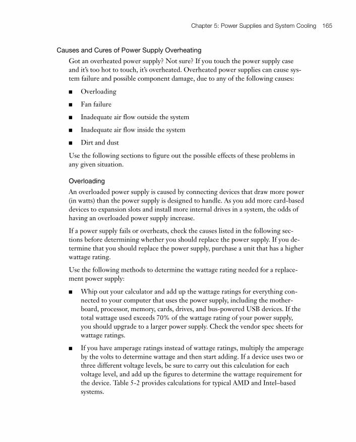
Causes and Cures of Power Supply Overheating
Got an overheated power supply? Not sure? If you touch the power supply caseand it’s too hot to touch, it’s overheated. Overheated power supplies can cause sys-tem failure and possible component damage, due to any of the following causes:
■ Overloading
■ Fan failure
■ Inadequate air flow outside the system
■ Inadequate air flow inside the system
■ Dirt and dust
Use the following sections to figure out the possible effects of these problems inany given situation.
Overloading
An overloaded power supply is caused by connecting devices that draw more power(in watts) than the power supply is designed to handle. As you add more card-baseddevices to expansion slots and install more internal drives in a system, the odds ofhaving an overloaded power supply increase.
If a power supply fails or overheats, check the causes listed in the following sec-tions before determining whether you should replace the power supply. If you de-termine that you should replace the power supply, purchase a unit that has a higherwattage rating.
Use the following methods to determine the wattage rating needed for a replace-ment power supply:
■ Whip out your calculator and add up the wattage ratings for everything con-nected to your computer that uses the power supply, including the mother-board, processor, memory, cards, drives, and bus-powered USB devices. If thetotal wattage used exceeds 70% of the wattage rating of your power supply,you should upgrade to a larger power supply. Check the vendor spec sheets forwattage ratings.
■ If you have amperage ratings instead of wattage ratings, multiply the amperageby the volts to determine wattage and then start adding. If a device uses two orthree different voltage levels, be sure to carry out this calculation for eachvoltage level, and add up the figures to determine the wattage requirement forthe device. Table 5-2 provides calculations for typical AMD and Intel–basedsystems.
05_9780789740472_ch05.qxd 9/23/09 3:07 PM Page 165

■ Use an interactive power supply sizing tool such as the calculators provided byeXtreme Outervision (www.extreme.outervision.com) or PC Power and Cool-ing (www.pcpowercooling.com)
Note that the recommended power supply shown for each example in Table 5-2 isconsiderably larger than the estimated wattage rating to make up for the reducedefficiency of some power supplies.
NOTE Some power supplies now feature power factor correction (PFC), whichuses special circuitry to achieve an efficiency of 95% or more, as opposed to the70%–75% efficiency of standard power supplies. Thus, when comparing two powersupplies with the same wattage rating, the power supply with PFC makes morewattage available to the system.
166 CompTIA A+ Cert Guide
Table 5-2 Calculating Power Supply Requirements
MicroATX system with integratedvideo
Full-size ATX system with SLI (dual graphicscards)
Components Wattage Components Wattage
AMD Athlon 64 X2 4000+Socket AM2
65 Intel Core 2 Quad Q6700 Socket 775 95
microATX motherboard 60 ATX motherboard 100
2GB RAM 30 3GB RAM 45
Rewritable DVD drive 30 Rewritable DVD drive 30
SATA hard disk 20 SATA hard disk 20
Two case fans 6 Three case fans 9
CPU fan 3 CPU fan 3
Integrated Video — High-end SLI video cards (2) 210(105×2)
Estimated Wattage 214 Estimated Wattage 472
Minimum Power Supply SizeRecommended (70% efficiencyassumed)
300 Minimum Power Supply Size Recom-mended (70% efficiency assumed)
700
05_9780789740472_ch05.qxd 9/23/09 3:07 PM Page 166

Fan Failure
The fan inside the power supply cools it and is partly responsible for cooling therest of the computer. If the fan fails, the power supply and the entire computer areat risk of damage. The fan also might stop turning as a symptom of other powerproblems.
A fan that stops immediately after the power comes on usually indicates incorrectinput voltage or a short circuit. If you turn off the system and turn it back on againunder these conditions, the fan will stop each time.
To determine whether the fan has failed, listen to the unit; it should make lessnoise if the fan has failed. You can also see the fan blades spinning rapidly on apower supply fan that is working correctly. If the blades aren’t turning, the fan hasfailed or is too clogged with dust to turn.
NOTE Note that if the fan has failed because of a short circuit or incorrect inputvoltage, you will not see any picture onscreen because the system cannot operate.
If the system starts normally but the fan stops turning later, this indicates a true fanfailure instead of a power problem.
CAUTION Should you try to replace a standard power supply fan? No. Becausethe power supply is a sealed unit, you would need to remove the cover from mostpower supplies to gain access to the fan. The wire coils inside a power supply retainpotentially lethal electrical charges. Instead, scrap the power supply and replace itwith a higher-rated unit. See the section “Removing and Replacing the PowerSupply” later in this chapter.
Chapter 5: Power Supplies and System Cooling 167
Inadequate Air Flow Outside the System
The power supply’s capability to cool the system depends in part on free airflowspace outside the system. If the computer is kept in a confined area (such as acloset or security cabinet) without adequate ventilation, power supply failures dueto overheating are likely.
05_9780789740472_ch05.qxd 9/23/09 3:07 PM Page 167
rr
168 CompTIA A+ Cert Guide
Even systems in ordinary office environments can have airflow problems; make surethat several inches of free air space exist behind the fan output for any computer.
Inadequate Air Flow Inside the System
As you have seen in previous chapters, the interior of the typical computer is amessy place. Wide ribbon cables used for hard and floppy drives, drive power cables,and expansion cards create small air dams that block air flow between the heatsources—such as the motherboard, CPU, drives, and memory modules—and the fanin the power supply.
You can do the following to improve air flow inside the computer:
■ Use cable ties to secure excess ribbon cable and power connectors out of theway of the fans and the power supply.
■ Replace any missing slot covers.
■ Make sure that auxiliary case fans and CPU fans are working correctly.
■ Use Serial ATA drives in place of conventional ATA hard drives (assuming thesystem supports Serial ATA); Serial ATA drives use very narrow data cables.
For more information about cooling issues, see the section “System Cooling,” laterin this chapter for details.
Dirt and Dust
Most power supplies, except for a few of the early ATX power supplies, use a cool-ing technique called negative pressure; in other words, the power supply fan workslike a weak vacuum cleaner, pulling air through vents in the case, past the compo-nents, and out through the fan. Vacuum cleaners are used to remove dust, dirt, cathairs, and so on from living rooms and offices, and even the power supply’s weak im-pression of a vacuum cleaner works the same way.
When you open a system for any kind of maintenance, look for the following:
■ Dirt, dust, hair, and gunk clogging the case vents
■ A thin layer of dust on the motherboard and expansion slots
■ Dirt and dust on the power supply vent and fans
Yuck! You never know what you’ll find inside of PC that hasn’t been cleaned out fora year or two. So how can you get rid of the dust and gunk? You can use either avacuum cleaner especially designed for computer use or compressed air to removedirt and dust from inside the system. If you use compressed air, be sure to spreadnewspapers around the system to catch the dirt and dust. If possible, remove thecomputer from the computer room so the dust is not spread to other equipment.
05_9780789740472_ch05.qxd 9/23/09 3:07 PM Page 168

Chapter 5: Power Supplies and System Cooling 169
Replacing Power Supply Form Factors and Connectors
When you shop for a power supply, you also need to make sure it can connect to yourmotherboard. There are two major types of power connectors on motherboards:
■ 20-pin, used by older motherboards in the ATX family
■ 24-pin, used by recent ATX/BTX motherboards requiring the ATX12V 2.xpower supply standard
Some high-wattage power supplies with 20-pin connectors might also include a20-pin to 24-pin adapter.
Some motherboards use power supplies that feature several additional connectorsto supply added power, as follows:
■ The four-wire ATX12V connector provides additional 12V power to themotherboard; this connector is sometimes referred to as a “P4” or “Pentium4” connector.
■ Many recent high-end power supplies use the eight-wire EPS12V connectorinstead of the ATX12V power connector.
■ Some older motherboards use a six-wire AUX connector to provide addi-tional power.
Figure 5-4 illustrates most of these connectors.
AUX secondary ATX12V secondary ATX primary (20-pin) ATX12V 2.2 primary (24-pin)
Figure 5-4 Typical power supply connectors to the motherboard.
Key Topic
05_9780789740472_ch05.qxd 9/23/09 3:07 PM Page 169

170 CompTIA A+ Cert Guide
Figure 5-5 lists the pinouts for the 20-pin and 24-pin ATX power supply connec-tors shown in Figure 5-4.
The power supply also powers various peripherals, such as the following:
■ PATA hard disks, CD and DVD optical drives, and case fans that do not pluginto the motherboard use a four-pin Molex power connector.
■ 3.5-inch floppy drives use a reduced-size version of the Molex power supplyconnector.
■ Serial ATA (SATA) hard disks use an L-shaped thinline power connector.
11 +3.3v Orange
12 -12v Blue
13 Ground Black
14 PS-On Green
15 Ground Black
16 Ground Black
17 Ground Black
18 -5v White
19 +5v Red
20 +5v Red
Orange +3.3v 1
Orange +3.3v 2
Black Ground 3
Red +5v 4
Black Ground 5
Red +5v 6
Black Ground 7
Gray Power Good 8
Purple +5v Standby 9
Yellow +12v 10
ATX 20-pin power connector (top view)
13 +3.3v Orange
14 -12v Blue
15 Ground Black
16 PS-On Green
17 Ground Black
18 Ground Black
19 Ground Black
20 NC White
21 +5v Red
22 +5v Red
23 +5v Red
24 Ground Black
Orange +3.3v 1
Orange +3.3v 2
Black Ground 3
Red +5v 4
Black Ground 5
Red +5v 6
Black Ground 7
Gray Power Good 8
Purple +5v Standby 9
Yellow +12v 10
Yellow +12v 11
Orange +3.3v 12
ATX 12V version 2.x 24-pin power connector (top view)
Figure 5-5 Pinouts for standard ATX 20-pin and 24-pin power connectors.
Figure 5-4 Typical power supply connectors to the motherboard.
05_9780789740472_ch05.qxd 9/23/09 3:07 PM Page 170

Chapter 5: Power Supplies and System Cooling 171
■ High-performance PCI Express x16 video cards that require additional 12Vpower use a PCI Express six-pin power cable.
Figure 5-6 illustrates these connectors compared to the 20- and 24-pin ATX pri-mary motherboard power connectors.
If your power supply doesn’t have enough connectors, you can add Y-splitters todivide one power lead into two, but these can short out and can also reduce yourpower supply’s efficiency. You can also convert a standard Molex connector into anSATA or floppy drive power connector with the appropriate adapter.
CAUTION Many recent and older Dell computers use proprietary versions of the20-pin or 24-pin ATX power supply connectors. Dell’s versions use a differentpinout that routes voltages to different wires than in standard power supplies.Consequently, if you plug a standard power supply into a Dell PC that uses theproprietary version, or use a regular motherboard as an upgrade for a model thathas the proprietary power supply, stand by for smoke and fire! To determine if aparticular Dell computer model requires a proprietary power supply, see the DellUpgrade Power Supplies section of the PC Power and Cooling website www.pcpower.com/products/power_supplies/dell/.
If your wattage calculations or your tests (covered later in this chapter) agree thatit’s time to replace the power supply, make sure the replacement will meet the fol-lowing criteria:
■ Have the same power supply connectors and the same pinout as the original.
■ Have the same form factor (shape, size, and switch location).
■ Have the same or higher wattage rating; a higher wattage rating is highlydesirable.
PCI Expressx16 video card
SATA hard disk
Floppy drive
PATA hard disk and optical drives
20-pin ATX 24-pin ATX12V v2.2
Figure 5-6 Typical peripheral power connectors.
Key Topic
05_9780789740472_ch05.qxd 9/23/09 3:07 PM Page 171

172 CompTIA A+ Cert Guide
■ Support any special features required by your CPU, video card, and mother-board, such as SLI support (support for PCI Express 6-pin connectors topower dual high-performance PCI Express x16 video cards), high levels of+12V power, and so on.
TIP To assure form factor connector compatibility, consider removing the oldpower supply and taking it with you if you plan to buy a replacement at retail. Ifyou are buying a replacement online, measure the dimensions of your existingpower supply to assure that a new one will fit properly in the system.
Removing and Replacing the Power Supply
If you have done your homework (checked compatibility and size and dug up thecase-opening instructions for your PC), installing a new power supply is one of theeasier repairs to make. You don’t need to fiddle with driver CDs or Windows Up-date to get the new one working. But, you do need to be fairly handy with a screw-driver or nut driver.
Typical power supplies are held in place by several screws that attach the powersupply to the rear panel of the computer. The power supply also is supported by ashelf inside the case, and screws can secure the power supply to that shelf. To re-move a power supply, follow these steps:
Step 1. Shut down the computer. If the power supply has an on-off switch, turnit off as well.
Step 2. Disconnect the AC power cord from the computer.
Step 3. Open the case to expose the power supply, which might be as simple asremoving the cover on a desktop unit, or as involved as removing bothside panels, front bezel, and case lid on a tower PC. Consult the docu-mentation that came with your computer to determine how to exposethe power supply for removal.
Step 4. Disconnect the power supply from the motherboard (refer to Figure 5-7). The catch securing the power supply connector must be released topermit the connector to be removed.
Step 5. Disconnect the power supply from all drives.
Step 6. Disconnect the power supply from the case and CPU fans.
Step 7. Remove the power supply screws from the rear of the computer case(see Figure 5-8).
Step 8. Remove any screws holding the power supply in place inside the case.(Your PC might not use these additional screws.)
Step 9. Disconnect the power supply switch from the case front (if present).
05_9780789740472_ch05.qxd 9/23/09 3:07 PM Page 172
Chapter 5: Power Supplies and System Cooling 173
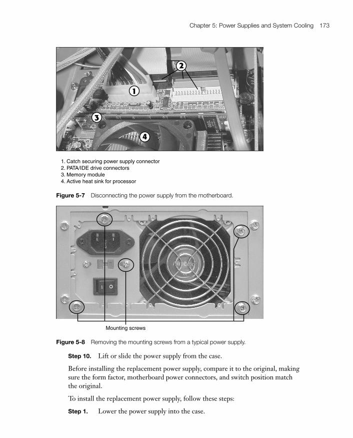
1. Catch securing power supply connector2. PATA/IDE drive connectors3. Memory module4. Active heat sink for processor
Figure 5-7 Disconnecting the power supply from the motherboard.
Mounting screws
Figure 5-8 Removing the mounting screws from a typical power supply.
Step 10. Lift or slide the power supply from the case.
Before installing the replacement power supply, compare it to the original, makingsure the form factor, motherboard power connectors, and switch position matchthe original.
To install the replacement power supply, follow these steps:
Step 1. Lower the power supply into the case.
05_9780789740472_ch05.qxd 9/23/09 3:07 PM Page 173

174 CompTIA A+ Cert Guide
Step 2. Attach the power supply to the shelf with screws if required.
Step 3. Attach the power supply to the rear of the computer case; line up theholes in the unit carefully with the holes in the outside of the case.
Step 4. Connect the power supply to the case, CPU fans, drives, and mother-board. Note that some power supplies provide a two-wire cable for useby motherboards that can monitor the power supply fan speed. Be sureto connect this cable as well as the main power cable and additionalpower cables as required.
Step 5. Check the voltage setting on the power supply. Change it to the correctvoltage for your location.
Step 6. Attach the AC power cord to the new power supply.
Step 7. Turn on the computer.
Step 8. Boot the system normally to verify correct operation, and then run thenormal shutdown procedure for the operating systems. If necessary, turnoff the system with the front power switch only.
Step 9. Close the case and secure it.
Testing Power Supplies with a Multimeter
How can you find out that a defective power supply is really defective? How canyou make sure that a cable has the right pinouts? Use a multimeter. A multimeter isone of the most flexible diagnostic tools around. It is covered in this chapter be-cause of its usefulness in testing power supplies, but it also can be used to test coax-ial, serial, and parallel cables, as well as fuses, resistors, and batteries.
Multimeters are designed to perform many different types of electrical tests, in-cluding the following:
■ DC voltage and polarity
■ AC voltage and polarity
■ Resistance (Ohms)
■ Diodes
■ Continuity
■ Amperage
All multimeters are equipped with red and black test leads. When used for voltagetests, the red is attached to the power source to be measured, and the black is at-tached to ground.
05_9780789740472_ch05.qxd 9/23/09 3:07 PM Page 174

Chapter 5: Power Supplies and System Cooling 175
Multimeters use two different readout styles: digital and analog. Digital multime-ters are usually autoranging, which means they automatically adjust to the correctrange for the test selected and the voltage present. Analog multimeters, or non–autoranging digital meters, must be set manually to the correct range and can bedamaged more easily by overvoltage. Figure 5-9 compares typical analog and digi-tal multimeters.
Multimeters are designed to perform tests in two ways: in series and in parallel.Most tests are performed in parallel mode, in which the multimeter is not part ofthe circuit but runs parallel to it. On the other hand, amperage tests require thatthe multimeter be part of the circuit, so these tests are performed in series mode.Many low-cost multimeters do not include the ammeter feature for testing amper-age (current), but you might be able to add it as an option.
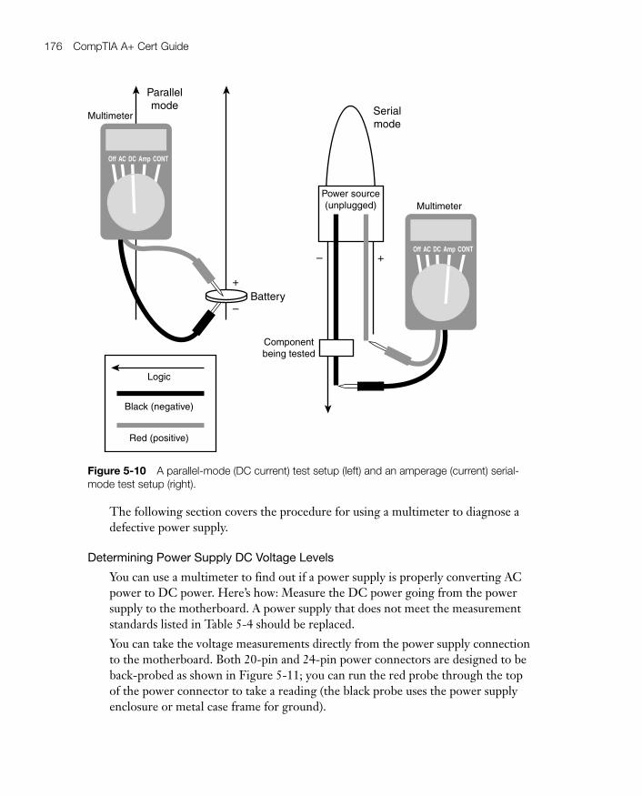
Figure 5-10 shows a typical parallel mode test (DC voltage for a motherboardCMOS battery) and the current (amperage) test, which is a serial-mode test.
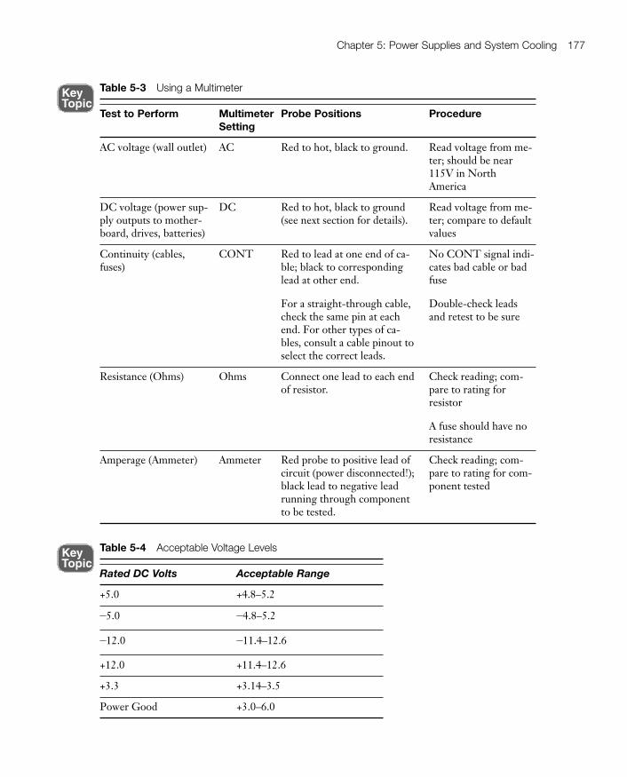
Table 5-3 summarizes the tests you can perform with a multimeter.
Figure 5-9 Typical analog (left) and digital (right) multimeters. Photos courtesy of ColacinoElectric Supply (www.colacinoelectric.com/).
05_9780789740472_ch05.qxd 9/23/09 3:07 PM Page 175
176 CompTIA A+ Cert Guide
Off AC DC Amp CONT
Multimeter
+
–Battery
Parallelmode
– +
Serialmode
Off AC DC Amp CONT
MultimeterPower source(unplugged)
Componentbeing tested
Logic
Black (negative)
Red (positive)
Figure 5-10 A parallel-mode (DC current) test setup (left) and an amperage (current) serial-mode test setup (right).
The following section covers the procedure for using a multimeter to diagnose adefective power supply.
Determining Power Supply DC Voltage Levels
You can use a multimeter to find out if a power supply is properly converting ACpower to DC power. Here’s how: Measure the DC power going from the powersupply to the motherboard. A power supply that does not meet the measurementstandards listed in Table 5-4 should be replaced.
You can take the voltage measurements directly from the power supply connectionto the motherboard. Both 20-pin and 24-pin power connectors are designed to beback-probed as shown in Figure 5-11; you can run the red probe through the topof the power connector to take a reading (the black probe uses the power supplyenclosure or metal case frame for ground).
05_9780789740472_ch05.qxd 9/23/09 3:07 PM Page 176
Chapter 5: Power Supplies and System Cooling 177
Table 5-4 Acceptable Voltage Levels
Rated DC Volts Acceptable Range
+5.0 +4.8–5.2
-5.0 -4.8–5.2
-12.0 -11.4–12.6
+12.0 +11.4–12.6
+3.3 +3.14–3.5
Power Good +3.0–6.0
Table 5-3 Using a Multimeter
Test to Perform MultimeterSetting
Probe Positions Procedure
AC voltage (wall outlet) AC Red to hot, black to ground. Read voltage from me-ter; should be near115V in North America
DC voltage (power sup-ply outputs to mother-board, drives, batteries)
DC Red to hot, black to ground(see next section for details).
Read voltage from me-ter; compare to defaultvalues
Continuity (cables,fuses)
CONT Red to lead at one end of ca-ble; black to correspondinglead at other end.
For a straight-through cable,check the same pin at eachend. For other types of ca-bles, consult a cable pinout toselect the correct leads.
No CONT signal indi-cates bad cable or badfuse
Double-check leadsand retest to be sure
Resistance (Ohms) Ohms Connect one lead to each endof resistor.
Check reading; com-pare to rating for resistor
A fuse should have noresistance
Amperage (Ammeter) Ammeter Red probe to positive lead ofcircuit (power disconnected!);black lead to negative leadrunning through componentto be tested.
Check reading; com-pare to rating for com-ponent tested
Key Topic
Key Topic
05_9780789740472_ch05.qxd 9/23/09 3:07 PM Page 177

178 CompTIA A+ Cert Guide
DC voltage readout
Red probe from multimeter back-probing +12V line
Multimeter’s mode selector switch set to DV voltage
Figure 5-11 Testing the +12V line on an ATX power supply. The voltage level indicated(+11.92V) is well within limits.
The multimeter also can be used to check the Power Good or Power OK line bypushing the red lead through the open top of the power connector. See Table 5-4for the acceptable voltage levels for each item.
If a power supply fails any of these measurements, replace it and retest the new unit.
Avoiding Power Supply Hazards
To avoid shock and fire hazards when working with power supplies, follow theseimportant guidelines:
■ Never disassemble a power supply or push metal tools through the openingsin the case— Long after you shut off the system, the wire coils inside thepower supply retain potentially fatal voltage levels. If you want to see the inte-rior of a power supply safely, check the websites of leading power supply ven-dors such as PC Power and Cooling.
■ If you are replacing the power supply in a Dell desktop computer, determinewhether the computer uses a standard ATX or Dell proprietary ATX powersupply— Many Dell computers built from September 1998 to the present usea nonstandard version of the ATX power supply with a different pinout for the
05_9780789740472_ch05.qxd 9/23/09 3:07 PM Page 178

Chapter 5: Power Supplies and System Cooling 179
power connector. Install a standard power supply on a system built to use aDell proprietary model, or upgrade from a Dell motherboard that uses theDell proprietary ATX design to a standard motherboard, and you can literallycause a power supply and system fire!
The proprietary Dell version of the 20-pin ATX connector has no 3.3V (orange) lines,and its Power Good (gray wire) line is pin 5, not pin 8 as with a standard ATX powersupply. The 3.3V (orange) wires are routed to the 6-pin Dell proprietary auxiliaryconnector. The proprietary Dell version of the 24-pin ATX connector also uses pin 5for Power Good, and provides 3.3V power (blue/white) through pins 11, 12, and 23,rather than through 1, 2, 12, and 13 as with a standard 24-pin ATX power supply.Make sure you buy a power supply made specifically for your Dell model.
■ Always use a properly wired and grounded outlet for your computer and itsperipherals— You can use a plug-in wiring tester to quickly determine if athree-prong outlet is properly wired; signal lights on the tester indicate theoutlet’s status (see Figure 5-12).
Power Protection Types
How well can a power supply work if it has poor-quality AC power to work with?Answer. Not very well.Because computers and many popular computer peripherals run on DC power thathas been converted from AC power, it’s essential to make sure that proper levels ofAC power flow to the computer and its peripherals. There are four problems youmight run into:
■ Overvoltages (spikes and surges)
■ Undervoltages (brownouts)
■ Power failure (blackouts)
■ Noisy power (interference)
Extremely high levels of transient or sustained overvoltages can damage the powersupply of the computer and peripherals, and voltage that is significantly lower thanrequired will cause the computer and peripherals to shut down. Shutdowns happenimmediately when all power fails. A fourth problem with power is interference;“noisy” electrical power can cause subtle damage, and all four types of problemsput the most valuable property of any computer, the data stored on the computer,at risk. Protect your computer’s power supply and other components with appro-priate devices:
■ Surge suppressors, which are also referred to as surge protectors
■ Battery backup systems, which are also referred to as UPS or SPS systems
■ Power conditioning devices
05_9780789740472_ch05.qxd 9/23/09 3:07 PM Page 179

180 CompTIA A+ Cert Guide
Figure 5-12 An outlet tester like this one can find wiring problems quickly. This outlet is wiredcorrectly.
Surge Suppressors
Stop that surge! While properly designed surge suppressors can prevent powersurges (chronic overvoltage) and spikes (brief extremely high voltage) from damag-ing your computer, low-cost ones are often useless because they lack sufficientcomponents to absorb dangerous surges. Surge suppressors range in price fromunder $10 to close to $100 per unit.
Both spikes and surges are overvoltages: voltage levels higher than the normal volt-age levels that come out of the wall socket. Spikes are momentary overvoltages,whereas surges last longer. Both can damage or destroy equipment and can comethrough data lines (such as RJ-11 phone or RJ-45 network cables) as well asthrough power lines. In other words, if you think of your PC as a house, spikes and
Key Topic
05_9780789740472_ch05.qxd 9/23/09 3:07 PM Page 180

Chapter 5: Power Supplies and System Cooling 181
surges can come in through the back door or the garage as well as through thefront door. Better “lock” (protect) all the doors. Many vendors sell data-line surgesuppressors.
How can you tell the real surge suppressors from the phonies? Check for a TVSS(transient voltage surge suppressor) rating on the unit. Multi-outlet power stripsdo not have a TVSS rating.
Beyond the TVSS rating, look for the following features to be useful in preventingpower problems:
■ A low TVSS let-through voltage level (400V AC or less). This might seemhigh compared to the 115V standard, but power supplies have been tested tohandle up to 800V AC themselves without damage.
■ A covered-equipment warranty that includes lightning strikes (one of thebiggest causes of surges and spikes).
■ A high Joule rating. Joules measure electrical energy, and surge suppressorswith higher Joule ratings can dissipate greater levels of surges or spikes.
■ Fusing that will prevent fatal surges from getting through.
■ Protection for data cables such as telephone/fax (RJ-11), network (RJ-45), orcoaxial (RG6).
■ EMI/RFI noise filtration (a form of line conditioning).
■ Site fault wiring indicator (no ground, reversed polarity warnings).
■ Fast response time to surges. If the surge suppressor doesn’t clamp fastenough, the surge can get through.
■ Protection against surges on hot, neutral, and ground lines.
If you use surge protectors with these features, you will minimize power problems.The site-fault wiring indicator will alert you to wiring problems that can negategrounding and can cause serious damage in ordinary use.
A surge suppressor that meets the UL 1449 or ANSI/IEEE C62.41 Category A(formerly IEEE 587 Category A) standards provides protection for your equip-ment. You might need to check with the vendor to determine if a particular unitmeets one of these standards.
NOTE To learn more about UL 1449 and the other UL standards it incorporates,see ulstandardsinfonet.ul.com/scopes/scopes.asp?fn=1449.html.
In preparing for the A+ Certification exam, you should pay particular attention tothe UL standard for surge suppressors and the major protection features just listed.
Key Topic
05_9780789740472_ch05.qxd 9/23/09 3:07 PM Page 181

182 CompTIA A+ Cert Guide
CAUTION If you’re looking for a way to negate the protection provided by high-quality surge protectors, plug them into an ungrounded electrical outlet. You’ll stillfind them in older homes and buildings.The two- to three-prong adapter you use to make grounded equipment plug into anungrounded outlet is designed to be attached to a ground such as a metal water pipe(that’s what the metal loop is for). If you can’t ground the adapter, don’t use a com-puter or other electronic device with it. If you do, sooner or later you’ll be sorry.
Battery Backup Units (UPS and SPS)
A UPS (uninterruptible power supply) is another name for a battery backup unit. AUPS provides emergency power when a power failure strikes (a blackout) or whenpower falls below minimum levels (a brownout).
There are two different types of UPS systems: true UPS and SPS systems. A trueUPS runs your computer from its battery at all times, isolating the computer andmonitor from AC power. There is no switchover time with a true UPS when ACpower fails because the battery is already running the computer. A true UPS inher-ently provides power conditioning (preventing spikes, surges, and brownouts fromreaching the computer) because the computer receives only battery power, not theAC power coming from the wall outlet. True UPS units are sometimes referred toas line-interactive battery backup units because the battery backup unit interactswith the AC line, rather than the AC line going directly to the computer and othercomponents.
An SPS (standby power supply) is also referred to as a UPS, but its design is quitedifferent. Its battery is used only when AC power fails. A momentary gap in power(about 1ms or less) occurs between the loss of AC power and the start of standbybattery power; however, this switchover time is far faster than is required to avoidsystem shutdown because computers can coast for several milliseconds before shut-ting down. SPS-type battery backup units are far less expensive than true UPSs,but work just as well as true UPSs when properly equipped with power-conditioning features.
NOTE In the rest of this section, the term UPS refers to both true UPS or SPSunits except as noted, because most backup units on the market technically are SPSbut are called UPS units by their vendors.Make sure you understand the differences between these units for the exam.
05_9780789740472_ch05.qxd 9/23/09 3:07 PM Page 182

Chapter 5: Power Supplies and System Cooling 183
Battery backup units can be distinguished from each other by differences in thefollowing:
■ Run times— The amount of time a computer will keep running on power fromthe UPS. A longer runtime unit uses a bigger battery and usually will cost morethan a unit with a shorter run time. Fifteen minutes is a minimum recommen-dation for a UPS for an individual workstation; much larger systems are recom-mended for servers that might need to complete a lengthy shutdown procedure.
■ Network support— Battery backup units made for use on networks are shippedwith software that broadcasts a message to users about a server shutdown sothat users can save open files and close open applications and then shuts downthe server automatically before the battery runs down.
■ Automatic shutdown— Some low-cost UPS units lack this feature, but it is es-sential for servers or other unattended units. The automatic shutdown featurerequires an available USB (or RS-232 serial) port and appropriate softwarefrom the UPS maker. If you change operating systems, you will need to updatethe software for your UPS to be supported by the new operating system.
■ Surge suppression features— Virtually all UPS units today have integratedsurge suppression, but the efficiency of integrated surge suppression can varyas much as separate units. Look for UL-1449 and IEEE-587 Category A rat-ings to find reliable surge suppression in UPS units.
Figure 5-13 illustrates the rear of a typical UPS unit.
NOTE Always plug a UPS directly into a wall outlet, not into a power strip orsurge suppressor.
Data Port Modem/Phone/Fax
TV
SS
GN
D
Wal
l O
utle
t
SURGE ONLY
BATTERY BACKUPCirc
uit B
reak
erP
ush
to R
eset
Figure 5-13 A typical UPS with integrated surge suppression for printers and other AC pow-ered devices, 10/100 Ethernet (including VoIP), and conventional telephony devices.
05_9780789740472_ch05.qxd 9/23/09 3:07 PM Page 183

184 CompTIA A+ Cert Guide
Buying the Correct-Sized Battery Backup System
Battery backups can’t run forever. But then, they’re not supposed to. This sectiondescribes how you can make sure you get enough time to save your files and shutdown your computer.
UPS units are rated in VA (volt-amps), and their manufacturers have interactivebuying guides you can use online or download to help you select a model with ade-quate capacity. If you use a UPS with an inadequate VA rating for your equipment,your runtime will be substantially shorter than it should be.
Here’s how to do the math: You can calculate the correct VA rating for your equip-ment by adding up the wattage ratings of your computer and monitor and multi-plying the result by 1.4. If your equipment is rated in amperage (amps), multiplythe amp rating by 120 (volts) to get the VA rating.
For example, my computer has a 450W power supply, which would require a630VA-rated UPS (450×1.4) and a 17-inch monitor that is rated in amps, notwatts. The monitor draws 0.9A, which would require a 108VA-rated UPS(0.9×120). Add the VA ratings together, and my computer needs a 750VA-ratedbattery backup unit or larger. Specifying a UPS with a VA rating at least twicewhat is required by the equipment attached to the UPS (for example, a 1500VA orhigher rating, based on a minimum requirement of 750VA) will greatly improvethe runtime of the battery.
In this example, a typical 750VA battery backup unit would provide about fiveminutes of runtime when used with my equipment. However, if I used a 1500VAbattery backup, I could increase my runtime to more than 15 minutes because myequipment would use only about half the rated capacity of the UPS unit.
If you need a more precise calculation, for example, if you will also power an addi-tional monitor or other external device, use the interactive sizing guides providedby battery backup vendors, such as American Power Conversion (www.apc.com).
CAUTION You should not attach laser printers to a UPS because their high currentdraw will cause the runtime of the battery to be very short. In most cases, only thecomputer and monitor need to be attached to the UPS. However, inkjet printersand external modems have low current draw and can be attached to the UPS withlittle reduction in runtime.
Power Conditioning Devices
Although power supplies are designed to work with voltages that do not exactlymeet the 120V or 240V standards, power that is substantially higher or lower thanwhat the computer is designed for can damage the system. Electrical noise on thepower line, even with power at the correct voltage, also causes problems because it
05_9780789740472_ch05.qxd 9/23/09 3:07 PM Page 184

Chapter 5: Power Supplies and System Cooling 185
disrupts the correct sinewave alternating-current pattern the computer, monitor,and other devices are designed to use.
Better-quality surge protectors often provide power filtration to handle electro-magnetic interference (EMI)/radio frequency interference (RFI) noise problemsfrom laser printers and other devices that generate a lot of electrical interference.However, to deal with voltage that is too high or too low, you need a true powerconditioner.
These units take substandard or overstandard power levels and adjust them to thecorrect range needed by your equipment. Some units also include high-qualitysurge protection features.
To determine whether you need a power-conditioning unit, you can contact yourlocal electric utility company to see if it loans or rents power-monitoring devices.Alternatively, you can rent them from power consultants. These units track powerlevel and quality over a set period of time (such as overnight or longer) and providereports to help you see the overall quality of power on a given line.
Moving surge- and interference-causing devices such as microwaves, vacuumcleaners, refrigerators, freezers, and furnaces to circuits away from the computercircuits will help minimize power problems. However, in older buildings, or duringtimes of peak demand, power conditioning might still be necessary. A true (line-interactive) UPS provides built-in power conditioning by its very nature (see theprevious discussion).
Troubleshooting Power ProblemsA dead system that gives no signs of life when turned on can be caused by the fol-lowing:
■ Defects in AC power to the system
■ Power supply failure or misconfiguration
■ Temporary short circuits in internal or external components
■ Power supply or other component failure
With four suspects, it’s time to play detective. Use the procedure outlined next tofind the actual cause of a dead system. If one of the test procedures in the followinglist corrects the problem, the item that was changed is the cause of the problem.Power supplies have a built-in safety feature that shuts down the unit immediatelyin case of short circuit. The following steps are designed to determine whether thepower problem is caused by a short circuit or another problem:
Step 1. Check the AC power to the system; a loose or disconnected power cord,a disconnected surge protector, a surge protector that has been turnedoff, or a dead AC wall socket will prevent a system from receiving power.
05_9780789740472_ch05.qxd 9/23/09 3:07 PM Page 185
186 CompTIA A+ Cert Guide
If the wall socket has no power, reset the circuit breaker in the electricalservice box for the location.
Step 2. Check the AC voltage switch on the power supply; it should be set to115V for North America. Turn off the power, reset the switch, andrestart the system if the switch was set to 230V.
Step 3. Check the keyboard connector; a loose keyboard connector could causea short circuit.
Step 4. Open the system and check for loose screws or other components suchas loose slot covers, modem speakers, or other metal items that cancause a short circuit. Correct them and retest.
Step 5. Verify that the cable from the front-mounted power switch is properlyconnected to the motherboard.
Step 6. Check for fuses on the motherboard (mainly found in very old systems).Turn off the power, replace any blown fuse on the motherboard with afuse of the correct rating, and retest. Never try to short-circuit or bypassfuses on the motherboard or anywhere else.
Step 7. Remove all expansion cards and disconnect power to all drives; restartthe system and use a multimeter to test power to the motherboard andexpansion slots per Table 5-4, earlier in this chapter.
Step 8. If the power tests within accepted limits with all peripherals disconnected,reinstall one card at a time and check the power. If the power tests withinaccepted limits, reattach one drive at a time and check the power.
Step 9. If a defective card or drive has a dead short, reattaching the defectivecard or drive should stop the system immediately upon power-up. Re-place the card or drive and retest.
Step 10. Test the Power Good line at the power supply motherboard connectorwith a multimeter.
It’s a long list, but chances are you will track down the offending component be-fore you reach the end of it.
System CoolingToday’s computers often run much hotter than systems of a few years ago, so it’simportant to understand how to keep the hottest-running components runningcooler. The following sections discuss the components that are most in need ofcooling and how to cool them.
05_9780789740472_ch05.qxd 9/23/09 3:07 PM Page 186

Chapter 5: Power Supplies and System Cooling 187
Passive and Active Heat Sinks
All processors require a heat sink. A heat sink is a finned metal device that radiatesheat away from the processor. In almost all cases, an active heat sink (a heat sinkwith a fan) is required for adequate cooling, unless the system case (chassis) is spe-cially designed to move air directly over the processor and a passive heat sink.
Although aluminum has been the most common material used for heat sinks, cop-per has better thermal transfer properties, and many designs mix copper and alu-minum components. Traditional active heat sinks include a cooling fan that restson top of the heat sink and pulls air past the heat sink in a vertical direction. How-ever, many aftermarket heat sinks use a horizontally mounted cooling fan and heatpipes to cool the process. Figure 5-14 compares typical examples of passive and ac-tive processor heat sinks used in ATX chassis.
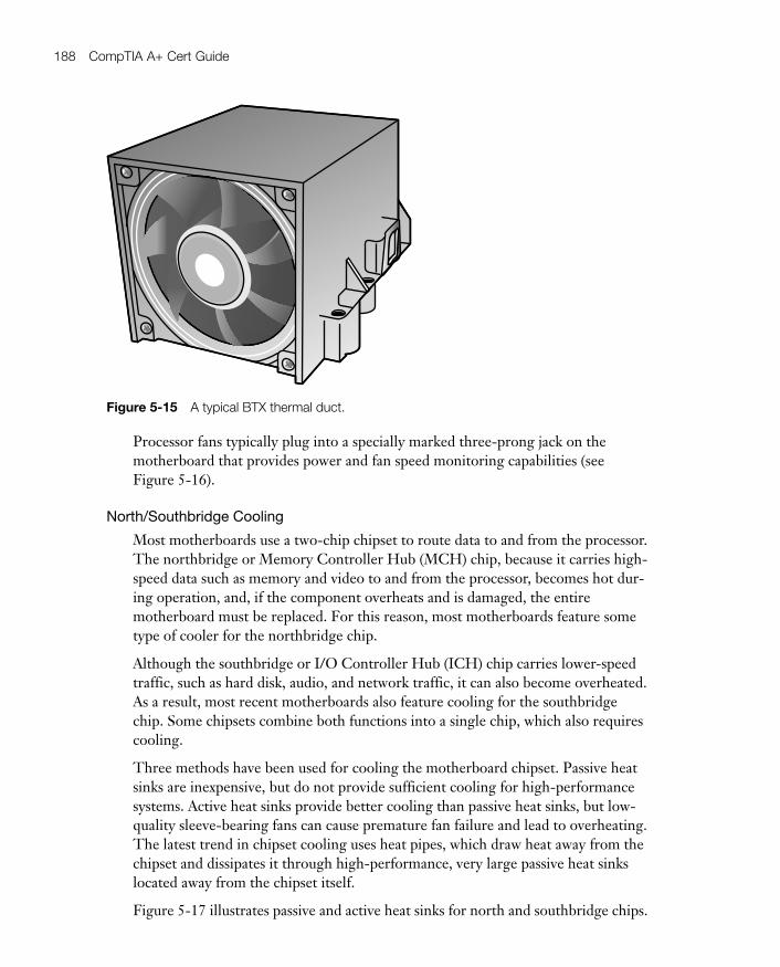
BTX chassis use a different approach to processor cooling. These chassis use athermal duct that fits over the processor and its heat sink. A cooling fan at one endof the duct directs air past the processor. Figure 5-15 illustrates this type of proces-sor cooler.
1. Active heat sink with horizontally-mounted fan and heat pipes
2. Active heat sink with vertically-mounted fan
3. Passive heat sink with heat pipes
4. Heat pipesarrows indicate
direction of airflow
Figure 5-14 Active and passive processor heat sinks. Note that the passive heat sink hasmore fins than the active heat sinks to enable it to provide adequate cooling.
Key Topic
05_9780789740472_ch05.qxd 9/23/09 3:07 PM Page 187
188 CompTIA A+ Cert Guide
Processor fans typically plug into a specially marked three-prong jack on themotherboard that provides power and fan speed monitoring capabilities (seeFigure 5-16).
North/Southbridge Cooling
Most motherboards use a two-chip chipset to route data to and from the processor.The northbridge or Memory Controller Hub (MCH) chip, because it carries high-speed data such as memory and video to and from the processor, becomes hot dur-ing operation, and, if the component overheats and is damaged, the entiremotherboard must be replaced. For this reason, most motherboards feature sometype of cooler for the northbridge chip.
Although the southbridge or I/O Controller Hub (ICH) chip carries lower-speedtraffic, such as hard disk, audio, and network traffic, it can also become overheated.As a result, most recent motherboards also feature cooling for the southbridgechip. Some chipsets combine both functions into a single chip, which also requirescooling.
Three methods have been used for cooling the motherboard chipset. Passive heatsinks are inexpensive, but do not provide sufficient cooling for high-performancesystems. Active heat sinks provide better cooling than passive heat sinks, but low-quality sleeve-bearing fans can cause premature fan failure and lead to overheating.The latest trend in chipset cooling uses heat pipes, which draw heat away from thechipset and dissipates it through high-performance, very large passive heat sinkslocated away from the chipset itself.
Figure 5-17 illustrates passive and active heat sinks for north and southbridge chips.
Figure 5-15 A typical BTX thermal duct.
05_9780789740472_ch05.qxd 9/23/09 3:07 PM Page 188

Chapter 5: Power Supplies and System Cooling 189
Figure 5-16 A typical processor active heat sink plugged into the motherboard.
Figure 5-17 Passive and active heat sinks for chipsets.
05_9780789740472_ch05.qxd 9/23/09 3:07 PM Page 189
190 CompTIA A+ Cert Guide
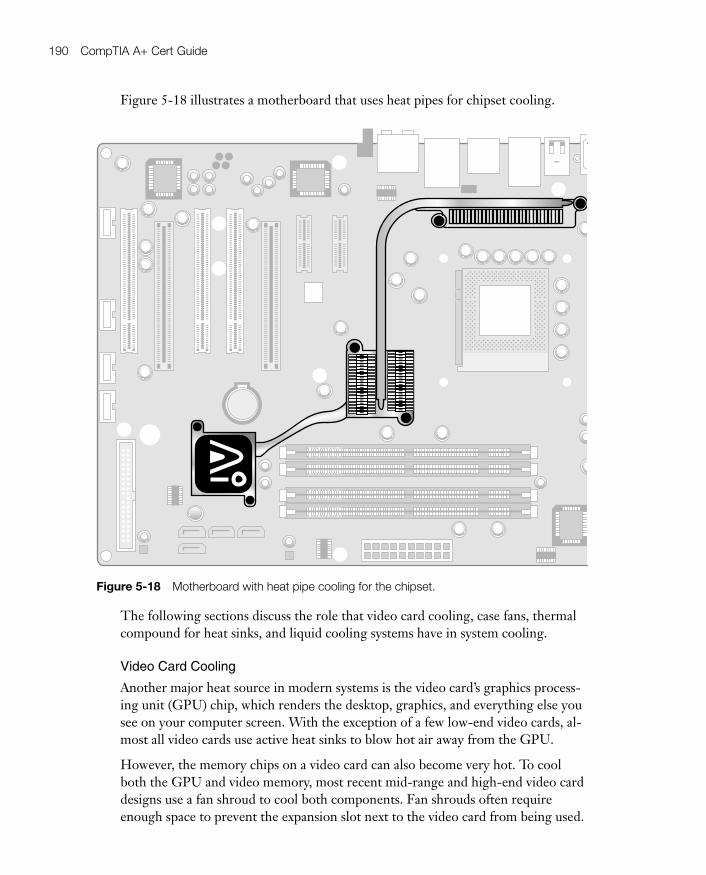
The following sections discuss the role that video card cooling, case fans, thermalcompound for heat sinks, and liquid cooling systems have in system cooling.
Video Card Cooling
Another major heat source in modern systems is the video card’s graphics process-ing unit (GPU) chip, which renders the desktop, graphics, and everything else yousee on your computer screen. With the exception of a few low-end video cards, al-most all video cards use active heat sinks to blow hot air away from the GPU.
However, the memory chips on a video card can also become very hot. To coolboth the GPU and video memory, most recent mid-range and high-end video carddesigns use a fan shroud to cool both components. Fan shrouds often requireenough space to prevent the expansion slot next to the video card from being used.
Figure 5-18 Motherboard with heat pipe cooling for the chipset.
Figure 5-18 illustrates a motherboard that uses heat pipes for chipset cooling.
05_9780789740472_ch05.qxd 9/23/09 3:07 PM Page 190

Chapter 5: Power Supplies and System Cooling 191
Figure 5-19 illustrates a typical video card with a two-slot fan shroud.
Case Fans
Most ATX chassis have provisions for at least two case fans: one at the front of thesystem, and one at the rear of the system. Case fans can be powered by the moth-erboard or by using a Y-splitter connected to a four-pin Molex power connector.Case fans at the front of the system should draw air into the system, while case fansat the rear of the system should draw air out of the system.
Figure 5.20 shows a typical rear case fan. You can plug fans like this into the three-prong chassis fan connection found on many recent motherboards or into the 4-pin Molex drive power connector used by hard drives. If the motherboard powerconnector is used, the PC Health or hardware monitor function found in many re-cent system BIOS setup programs can monitor fan speed. See Chapter 4, “BIOS,”for a typical example.
NOTE Some case fans that can be powered by a Molex power connector include aspecial power cable that permits the fan speed to be monitored by the mother-board, even though the motherboard is not used to power the fan.
Figure 5-19 The GeForce 8800 GTS is a high-performance PCI Express x16 video card thatrequires a two-slot fan shroud.
05_9780789740472_ch05.qxd 9/23/09 3:07 PM Page 191
192 CompTIA A+ Cert Guide
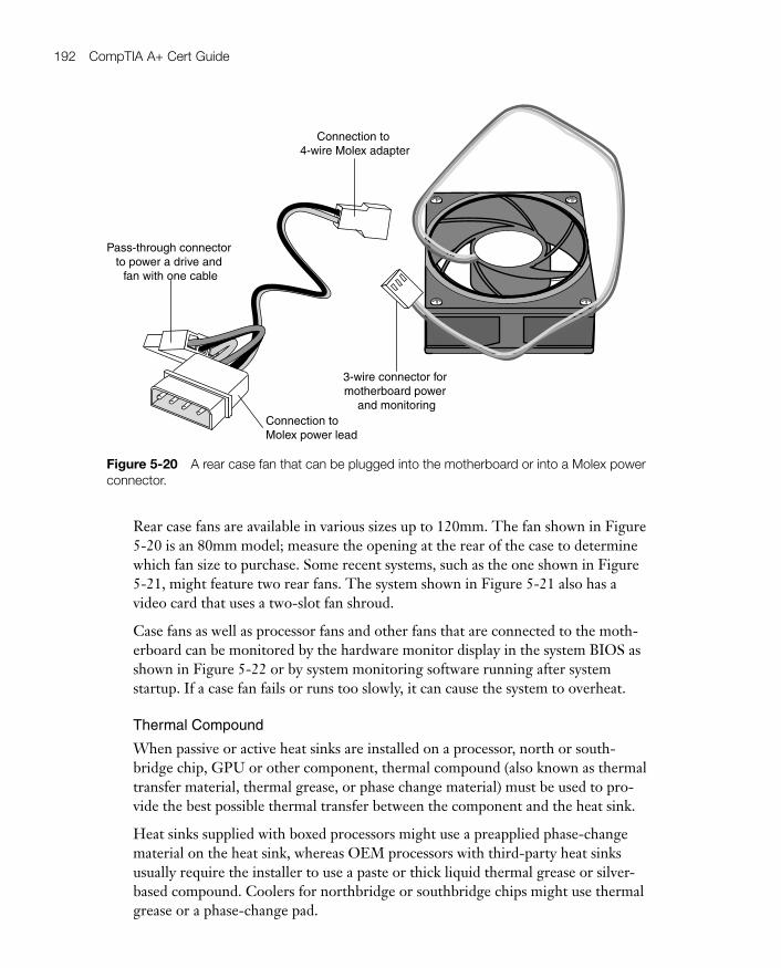
3-wire connector for motherboard power
and monitoringConnection to Molex power lead
Pass-through connector to power a drive and
fan with one cable
Connection to 4-wire Molex adapter
Figure 5-20 A rear case fan that can be plugged into the motherboard or into a Molex powerconnector.
Rear case fans are available in various sizes up to 120mm. The fan shown in Figure5-20 is an 80mm model; measure the opening at the rear of the case to determinewhich fan size to purchase. Some recent systems, such as the one shown in Figure5-21, might feature two rear fans. The system shown in Figure 5-21 also has avideo card that uses a two-slot fan shroud.
Case fans as well as processor fans and other fans that are connected to the moth-erboard can be monitored by the hardware monitor display in the system BIOS asshown in Figure 5-22 or by system monitoring software running after systemstartup. If a case fan fails or runs too slowly, it can cause the system to overheat.
Thermal Compound
When passive or active heat sinks are installed on a processor, north or south-bridge chip, GPU or other component, thermal compound (also known as thermaltransfer material, thermal grease, or phase change material) must be used to pro-vide the best possible thermal transfer between the component and the heat sink.
Heat sinks supplied with boxed processors might use a preapplied phase-changematerial on the heat sink, whereas OEM processors with third-party heat sinksusually require the installer to use a paste or thick liquid thermal grease or silver-based compound. Coolers for northbridge or southbridge chips might use thermalgrease or a phase-change pad.
05_9780789740472_ch05.qxd 9/23/09 3:07 PM Page 192

Chapter 5: Power Supplies and System Cooling 193
Case fans Video card with two-slot fan shroud
Figure 5-21 A system with two rear case fans.
CPU (processor) fan speed
System (chassis) fan speed
Figure 5-22 The PC Health (system monitor) dialog in a typical system BIOS.
Key Topic
05_9780789740472_ch05.qxd 9/23/09 3:07 PM Page 193

194 CompTIA A+ Cert Guide
If the thermal material is preapplied to the heat sink, make sure you remove theprotective tape before you install the heat sink. If a third-party heat sink is used, orif the original heat sink is removed and reinstalled, carefully remove any existingthermal transfer material from the heat sink and processor die surface. Then, applynew thermal transfer material to the processor die before you reinstall the heatsink on the processor.
Figure 5-23 illustrates the application of thermal compound to a northbridge chipbefore attaching a heat sink.
CAUTION Never operate a system before attaching the heat sink to the processorwith the appropriate thermal transfer material. The processor could be destroyedby overheating in just a few moments. Most recent systems have thermal safeguardsthat shut down the system in the event of processor overheating, but if these safe-guards fail, there could also be damage to the processor.
Figure 5-23 Applying thermal grease to the Northbridge chip.
05_9780789740472_ch05.qxd 9/23/09 3:07 PM Page 194

Chapter 5: Power Supplies and System Cooling 195
Liquid Cooling Systems
Liquid cooling systems for processors, motherboard chipsets, and GPUs are nowavailable. Some are integrated into a custom case, whereas others can be retrofittedinto an existing system that has openings for cooling fans.
Liquid cooling systems attach a liquid cooling unit instead of an active heat sink tothe processor and other supported components. A pump moves the liquid (whichmight be water or a special solution, depending upon the cooling system) throughthe computer to a heat exchanger, which uses a fan to cool the warm liquid beforeit is sent back to the processor. Liquid cooling systems are designed primarily forvery high-performance systems, especially overclocked systems. It’s essential thatonly approved cooling liquids and hoses be used in these systems (check with cool-ing system vendors for details); unauthorized types of liquids or hoses could leakand corrode system components.
Figure 5-24 illustrates a typical liquid cooling system for cooling the processor.
Figure 5-24 A typical liquid cooling system.
05_9780789740472_ch05.qxd 9/23/09 3:07 PM Page 195
196 CompTIA A+ Cert Guide
Exam Preparation Tasks
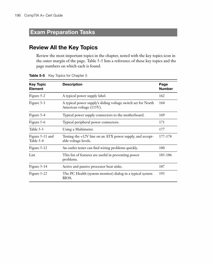
Review All the Key TopicsReview the most important topics in the chapter, noted with the key topics icon inthe outer margin of the page. Table 5-5 lists a reference of these key topics and thepage numbers on which each is found.
Table 5-5 Key Topics for Chapter 5
Key TopicElement
Description PageNumber
Figure 5-2 A typical power supply label. 162
Figure 5-3 A typical power supply’s sliding voltage switch set for NorthAmerican voltage (115V).
164
Figure 5-4 Typical power supply connectors to the motherboard. 169
Figure 5-6 Typical peripheral power connectors. 171
Table 5-3 Using a Multimeter. 177
Figure 5-11 andTable 5-4
Testing the +12V line on an ATX power supply, and accept-able voltage levels.
177-178
Figure 5-12 An outlet tester can find wiring problems quickly. 180
List This list of features are useful in preventing power problems.
185-186
Figure 5-14 Active and passive processor heat sinks. 187
Figure 5-22 The PC Health (system monitor) dialog in a typical systemBIOS.
193
05_9780789740472_ch05.qxd 9/23/09 3:07 PM Page 196

Chapter 5: Power Supplies and System Cooling 197
Definitions of Key TermsDefine the following key terms from this chapter, and check your answers in theglossary.
AC
DC
Power Supply
Surge Protector
UPS
Troubleshooting ScenarioYou are working on a computer that is overheating. What steps should you take tomake sure the power supply is not being overloaded?
Refer to Appendix A, “Answers to the ‘Do I Know This Already?’ Quizzes andTroubleshooting Scenarios,” for the answer.
05_9780789740472_ch05.qxd 9/23/09 3:07 PM Page 197

This chapter covers the following subjects:
■ RAM Basics— This section talks about what RAM does, how it works, andhow it relates to the rest of the computer system.
■ RAM Types— In this section you learn about the various types of RAMavailable, including SDRAM, DDR, and Rambus. Their architecture, ca-pacity, and speed will also be described.
■ Operational Characteristics— This section describes the features of memorymodules and types of memory like ECC, EDO, registered, and unbuffered.
■ Installing Memory Modules— This section demonstrates how to installSIMMs and DIMMs properly.
■ Troubleshooting Memory— This section covers some issues you might en-counter with RAM due to incompatible memory speeds and types.
■ Preventative Maintenance for Memory— Due to the possibility of memoryoverheating, this section describes some measures you can take to keep yourmemory modules clean and protected.
This chapter covers a portion of the CompTIA A+ 220-701 objectives 1.2 and1.6 and CompTIA A+ 220-702 objectives 1.1 and 1.2
06_9780789740472_ch06.qxd 9/23/09 3:15 PM Page 198