Power Semiconductor Switching Deviceseebag/EE-442-642-Power switching devices.pdf · also on the...
17
Power Semiconductor Switching Devices EE 442-642
Transcript of Power Semiconductor Switching Deviceseebag/EE-442-642-Power switching devices.pdf · also on the...

Power Semiconductor Switching Devices
EE 442-642
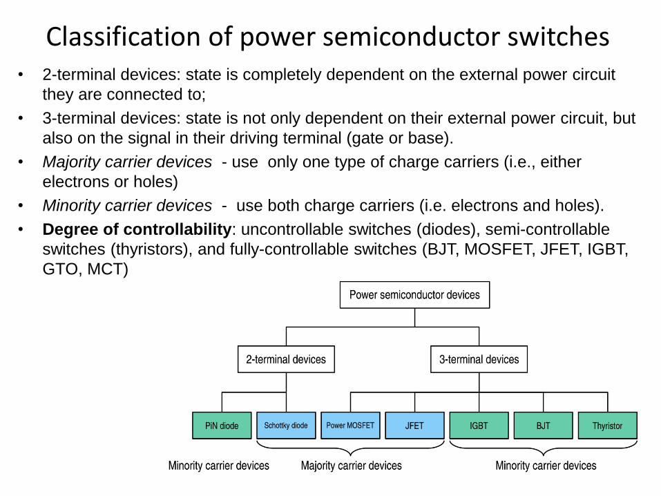
Classification of power semiconductor switches • 2-terminal devices: state is completely dependent on the external power circuit
they are connected to;
• 3-terminal devices: state is not only dependent on their external power circuit, but
also on the signal in their driving terminal (gate or base).
• Majority carrier devices - use only one type of charge carriers (i.e., either
electrons or holes)
• Minority carrier devices - use both charge carriers (i.e. electrons and holes).
• Degree of controllability: uncontrollable switches (diodes), semi-controllable
switches (thyristors), and fully-controllable switches (BJT, MOSFET, JFET, IGBT,
GTO, MCT)
Brief History
• Power semiconductor devices first appeared in 1952 with the
introduction of the power diode.
• The thyristor appeared in 1957. Thyristors are able to withstand very
high reverse breakdown voltage and are also capable of carrying high
current. One disadvantage of the thyristor is that once it is in the
conducting state it cannot be turned off by external control.
• The first bipolar transistors devices with substantial power handling
capabilities were introduced in the 1960s. These components
overcame some limitations of the thyristors because they can be turned
on or off with a control signal.
• With the improvements of the Metal Oxide Semiconductor technology,
power MOSFETs became available in the late 1970s. These devices
allow operation at higher frequency than bipolar transistors, but are
limited to low voltage applications.
• The Insulated Gate Bipolar Transistor (IGBT) developed in the 1980s
became widely available in the 1990s. This component has the power
handling capability of the bipolar transistor, with the advantages of the
isolated gate drive of the power MOSFET.
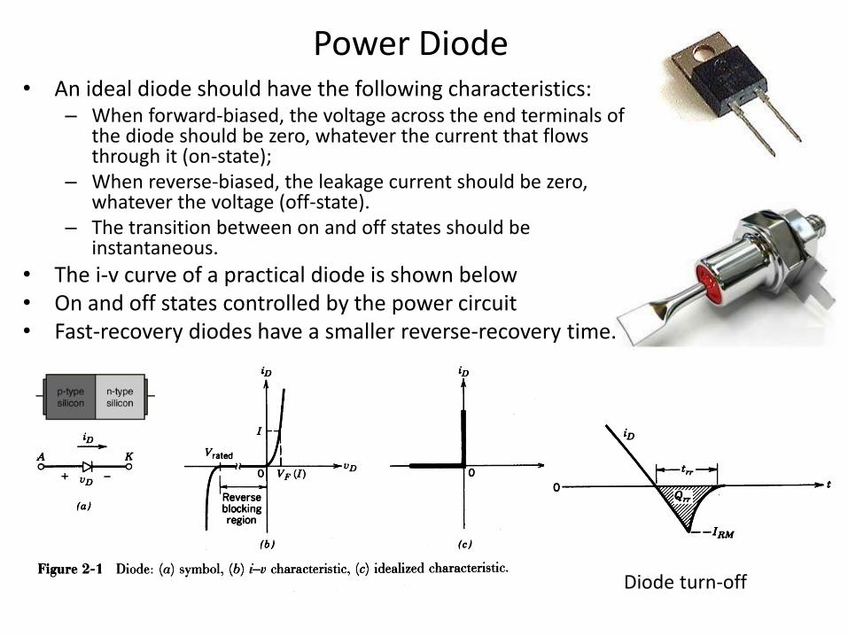
Power Diode • An ideal diode should have the following characteristics:
– When forward-biased, the voltage across the end terminals of the diode should be zero, whatever the current that flows through it (on-state);
– When reverse-biased, the leakage current should be zero, whatever the voltage (off-state).
– The transition between on and off states should be instantaneous.
• The i-v curve of a practical diode is shown below • On and off states controlled by the power circuit • Fast-recovery diodes have a smaller reverse-recovery time.
Diode turn-off
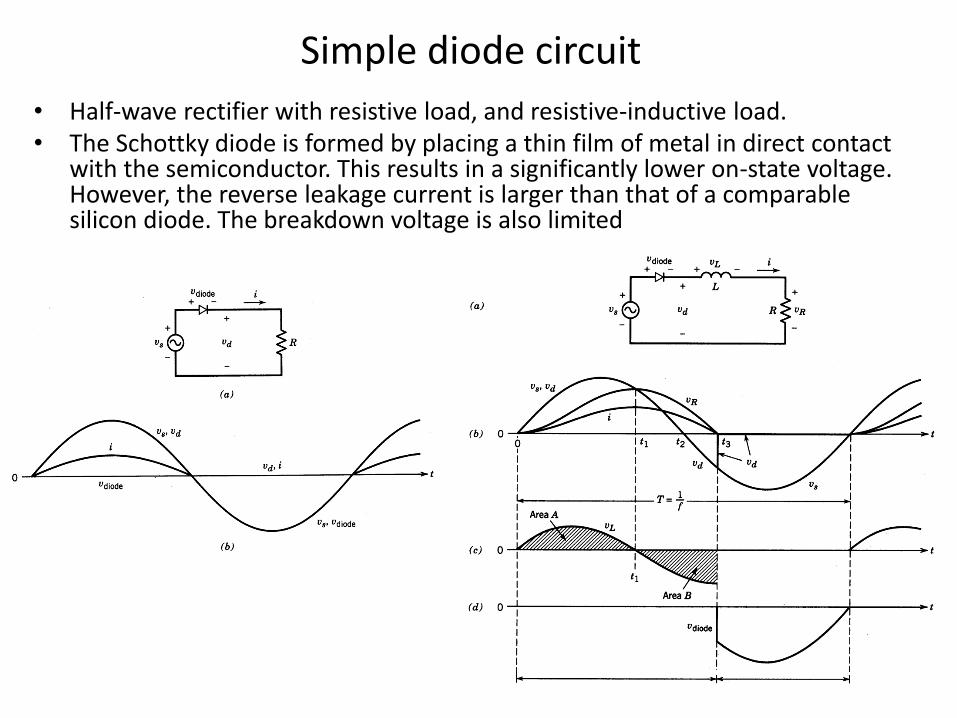
Simple diode circuit
• Half-wave rectifier with resistive load, and resistive-inductive load. • The Schottky diode is formed by placing a thin film of metal in direct contact
with the semiconductor. This results in a significantly lower on-state voltage. However, the reverse leakage current is larger than that of a comparable silicon diode. The breakdown voltage is also limited
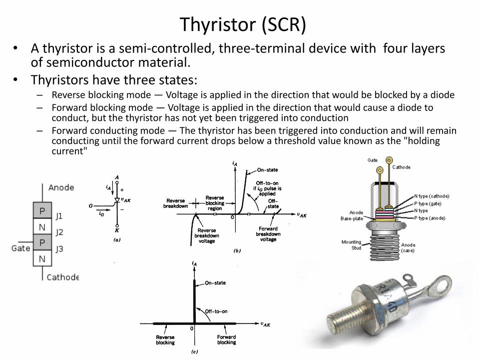
Thyristor (SCR) • A thyristor is a semi-controlled, three-terminal device with four layers
of semiconductor material. • Thyristors have three states:
– Reverse blocking mode — Voltage is applied in the direction that would be blocked by a diode – Forward blocking mode — Voltage is applied in the direction that would cause a diode to
conduct, but the thyristor has not yet been triggered into conduction – Forward conducting mode — The thyristor has been triggered into conduction and will remain
conducting until the forward current drops below a threshold value known as the "holding current"
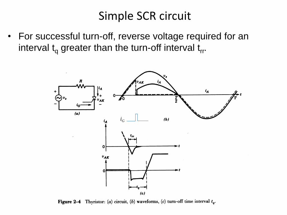
Simple SCR circuit
• For successful turn-off, reverse voltage required for an
interval tq greater than the turn-off interval trr.
iG
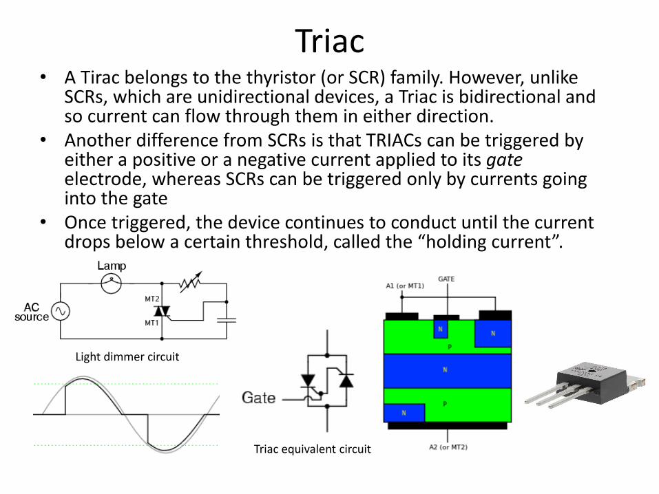
Triac • A Tirac belongs to the thyristor (or SCR) family. However, unlike
SCRs, which are unidirectional devices, a Triac is bidirectional and so current can flow through them in either direction.
• Another difference from SCRs is that TRIACs can be triggered by either a positive or a negative current applied to its gate electrode, whereas SCRs can be triggered only by currents going into the gate
• Once triggered, the device continues to conduct until the current drops below a certain threshold, called the “holding current”.
Triac equivalent circuit
Light dimmer circuit
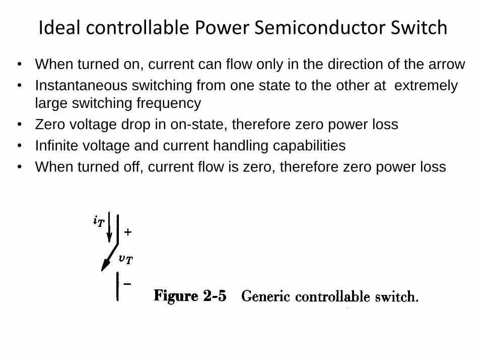
Ideal controllable Power Semiconductor Switch
• When turned on, current can flow only in the direction of the arrow
• Instantaneous switching from one state to the other at extremely
large switching frequency
• Zero voltage drop in on-state, therefore zero power loss
• Infinite voltage and current handling capabilities
• When turned off, current flow is zero, therefore zero power loss
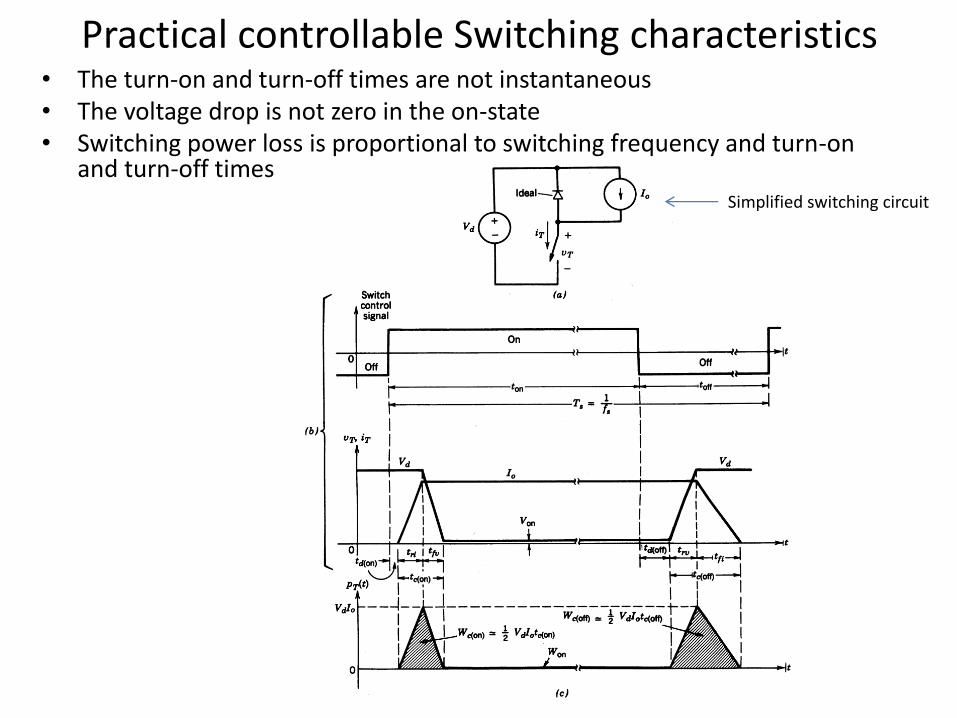
Practical controllable Switching characteristics • The turn-on and turn-off times are not instantaneous • The voltage drop is not zero in the on-state • Switching power loss is proportional to switching frequency and turn-on
and turn-off times Simplified switching circuit
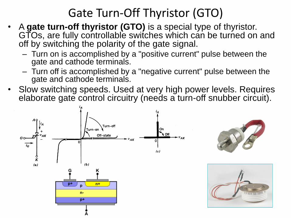
Gate Turn-Off Thyristor (GTO) • A gate turn-off thyristor (GTO) is a special type of thyristor.
GTOs, are fully controllable switches which can be turned on and off by switching the polarity of the gate signal. – Turn on is accomplished by a "positive current" pulse between the
gate and cathode terminals.
– Turn off is accomplished by a "negative current" pulse between the gate and cathode terminals.
• Slow switching speeds. Used at very high power levels. Requires elaborate gate control circuitry (needs a turn-off snubber circuit).
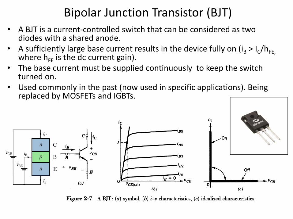
Bipolar Junction Transistor (BJT) • A BJT is a current-controlled switch that can be considered as two
diodes with a shared anode. • A sufficiently large base current results in the device fully on (iB > IC/hFE,
where hFE is the dc current gain). • The base current must be supplied continuously to keep the switch
turned on. • Used commonly in the past (now used in specific applications). Being
replaced by MOSFETs and IGBTs.
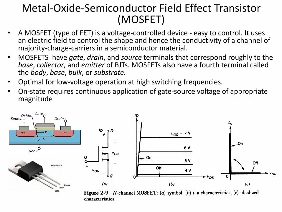
Metal-Oxide-Semiconductor Field Effect Transistor (MOSFET)
• A MOSFET (type of FET) is a voltage-controlled device - easy to control. It uses an electric field to control the shape and hence the conductivity of a channel of majority-charge-carriers in a semiconductor material.
• MOSFETS have gate, drain, and source terminals that correspond roughly to the base, collector, and emitter of BJTs. MOSFETs also have a fourth terminal called the body, base, bulk, or substrate.
• Optimal for low-voltage operation at high switching frequencies. • On-state requires continuous application of gate-source voltage of appropriate
magnitude
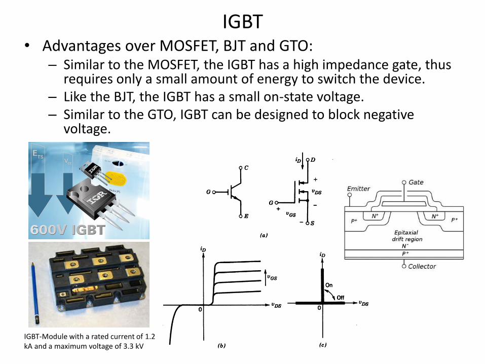
IGBT • Advantages over MOSFET, BJT and GTO:
– Similar to the MOSFET, the IGBT has a high impedance gate, thus requires only a small amount of energy to switch the device.
– Like the BJT, the IGBT has a small on-state voltage. – Similar to the GTO, IGBT can be designed to block negative
voltage.
IGBT-Module with a rated current of 1.2 kA and a maximum voltage of 3.3 kV
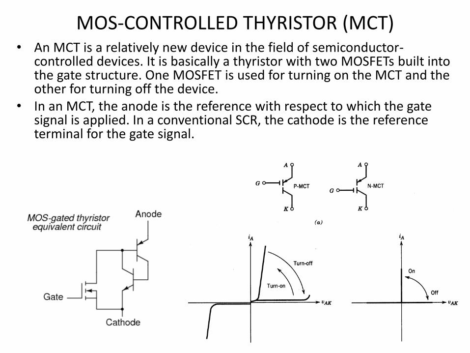
MOS-CONTROLLED THYRISTOR (MCT) • An MCT is a relatively new device in the field of semiconductor-
controlled devices. It is basically a thyristor with two MOSFETs built into the gate structure. One MOSFET is used for turning on the MCT and the other for turning off the device.
• In an MCT, the anode is the reference with respect to which the gate signal is applied. In a conventional SCR, the cathode is the reference terminal for the gate signal.
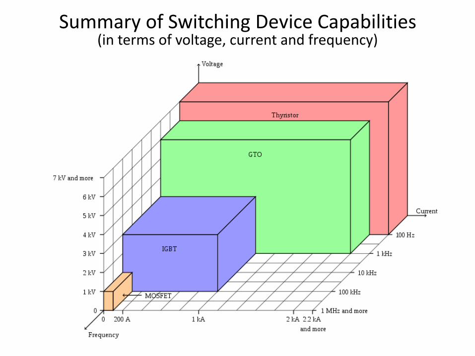
Summary of Switching Device Capabilities (in terms of voltage, current and frequency)
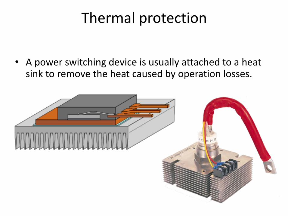
Thermal protection
• A power switching device is usually attached to a heat sink to remove the heat caused by operation losses.