Power Quality For The Digital Age - EP2000ep2000.com/uploads/EP_WhitePaper_VFD_NoiseSolution.pdf ·...
5
www.ep2000.com • 800.500.7436 Power Quality For e Digital Age THE EP VFD NOISE SOLUTION Report by EP Research & Development
Transcript of Power Quality For The Digital Age - EP2000ep2000.com/uploads/EP_WhitePaper_VFD_NoiseSolution.pdf ·...
www.ep2000.com • 800.500.7436
Power Quality For The Digital Age
THE EP VFD NOISE SOLUTION
Report by EP Research & Development
Magdalena
Typewritten Text
Copyright©EP2009
Optimizing Production
Variable frequency drives (VFD), have revolutionized the production process of nearly
every industry. It is one of the most significant advancements to the modern facility.
VFD’s control motor outputs, change speeds as needed, control torque, reduce energy
consumption and even report operating information. These benefits have led to the
widespread use of VFD’s.
A VFD is a system for controlling the rotational speed of an alternating current (AC)
electric motor by manipulating the frequency of the electrical power supplied to the
motor. The equation for motor speed is 120*f/P where ‘f’ is the frequency of operation
and ‘P’ is the number is poles on motor. To vary the speed of the motor either number of
poles should be decreased or the frequency of operation should be increased. Changing
the frequency is the most efficient option. While the benefits of VFD’s are undeniable,
these benefits also come with a significant price. Varying frequency generates noise and
severely degrades power quality.
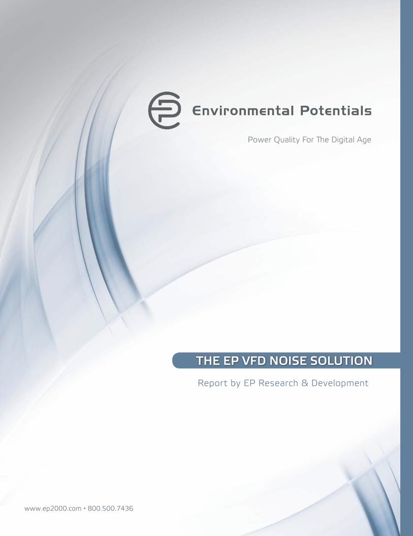
Figure 1: Schematic diagram of VFD with Motor in a facility
Sine Wave Power
Variable Frequency
Power
Power Conversion
Operator Interface
Power Conversion
Variable Frequency Controller
Mechanical Power
AC Motor
1750F
RUN STOP
1 2
Isolating the Problem
It is a common misconception that electrical noise generated by a VFD flows only towards
AC motor, this is not true. Variable frequency power is a pulse width modulated signal,
or a sine wave with squared notches. A waveform with notches is also called as non-
sinusoidal electric signal. While motors used in industrial applications are tough enough to
handle the non-sinusoidal signal, these waves will also cause electrical noise in the supply

Figure 2: Voltage and current waveforms on the supply side of phase 1 when the VFD is not connected
Figure 3: Voltage and current waveforms on the supply side of phase 1 when the VFD is connected
Figures 2 and 3 clearly demonstrate the nonlinearity of the current wave is increased when
the VFD is turned on. Figure 2 clearly shows notches on both peaks of the waveform.
Both measurements were recorded on the supply side of the VFD. This means nonlinear
current signal travels to the other loads connected in the facility significantly deteriorating
the power quality. This affects the VFD as well as the other equipment in the building.
side of the VFD. Return path of currents, bearing currents, and ground loops at the AC
motor are responsible for causing electrical noise to flow towards supply side of the VFD.
To demonstrate this theory, Environmental Potentials’ research and development
department setup a motor with a VFD and recorded the following readings. Measurements
are taken at the supply side of the VFD.

VFD’s are designed with sensitive electronic components. These components are
extremely sensitive to the nonsinusoidal nature of the electrical signal and the infinite
frequency rise times that result in the way the sinusoidal waveform is manipulated. This
non-sinusoidal signal causes board level components to become non-sequential, switching
noise generators resulting in erratic behavior and/or failure of the VFD.
Nonlinear nature of the electrical signal will cause losses in the magnetic cores of
conductors, motor windings, and transformers such as eddy currents and hysteresis
losses. These losses will cause failure, increase inefficiency and shorten the duty lifecycle
of the transformers and motors.i
Gap in Technology
Traditional power quality equipment is not the solution for noise. This equipment allows
high frequency currents and common mode currents to circulate within earth ground.
These circulating currents degrade the insulation of motors windings, bearings and also
interfere with other systems (sensors, PLC’s/PAC’s, industrial computers, etc).i VFD’s are
inter-harmonics source generators causing amplification of electrical noise in the rest of
the facility. This causes voltage fluctuations, flicker, and line losses in the facility. Studies
have shown that the inter-harmonics caused by VFD’s can even cause voltage flicker in
neighboring facilities.ii
In order to protect VFD’s from the damaging effects caused by nonlinear nature of the
electrical signal, facility engineers will add additional impedance. Sources of additional
impedances include AC line reactors and isolation transformers. However, due to
the common practice of a powering a Delta VFD from a Wye end of the distribution
transformer without running a neutral to the VFD, the additional impedance sources will
create ground loops and amplify resonance the electrical noise.
EP’s Solution for Noise
With all of the benefits offered by VFD’s, their use will continue to rise. Facility managers
must remain diligent with efforts to combat harmful noise generated by the normal
operation of VFD’s. The solution to destructive noise is to install a sine wave tracking
filter on the supply side of the VFD.iii EP’s patented waveform correction technology
is a powerful low pass filter, which not only removes the electrical noise and ground
loops from the system, but also maintains the sinusoidal nature of the electrical signal
throughout the facility.

www.ep2000.com • 800.500.7436
Figure 4: Frequency noise from 3-100kHz on the neutral wire at the supply side of VFD before EP installation
Figure 5: Frequency noise from 3-100kHz on the neutral wire at the supply side of VFD immediately after EP installation
Figures 4 and 5 demonstrate the immediate noise reduction after installing EP’s waveform correction technology. The advantage of EP’s patented technology is that it converts noise into heat inside of the unit.
Environmental Potentials is the solution to noisy drives.