Power-Quality Enhancer Using an Artificial Bee Colony ... · Power-Quality Enhancer Using an...
12
Power-Quality Enhancer Using an Artificial Bee Colony-Based Optimal-Controlled Shunt Active-Power Filter ESSAMUDIN ALI EBRAHIM Power-Electronics and Energy-Conversion Department Electronics Research Institute El-tahrir Street, P. O. Code 12662 Dokki, Cairo, EGYPT [email protected] & [email protected] Abstract: - Variable speed drives (VSDs) use power electronic components - as controlled switches - which distort the sinusoidal current and voltage waveforms of AC grid due to harmonic injection at the point of common coupling (PCC). These harmonics and distortions are propagated through the power network and affect all other connected loads. So, the shunt active power filter (SAPF) is one of the proposed tools to mitigate these harmonics. In this paper, an artificial bee colony (ABC)- based optimal-controlled SAPF is proposed to provide instantaneous reactive power compensation required for harmonic mitigation of a separately excited DC motor – as a dynamic load - fed from uncontrolled- bridge rectifier via a GTO- thyristorized-DC chopper. The proposed technique uses three-phase hysteresis-current controller inverter connected with reactors as an active power filter. The dc- link voltage of that inverter is controlled using PID- controller. Tuning of the PID-parameters depends on artificial bee colony optimization. The proposed ABC- controller is employed to search for optimal controller parameters by minimizing the error signal - as an objective function - of a dc-link for the inverter. The performance of the proposed filter that called ABC-SAPF is carried out by simulation under steady-state and dynamic operations using MATLAB/ SIMULINK software. Also, these results are compared with other control approaches as ANN and fuzzy logic. The results show that it is an effective in enhancement dynamic of power quality and also the overall total harmonic distortion (THD) is minimized to safe-limit according to the harmonic restriction standards such as IEEE-519 and IEC 61000. Key-Words: - Artificial bee colony, power quality, hysteresis current controller, shunt active power filter, Objective function, Scout and Onlookers, point of common coupling, total harmonic distortion. 1 Introduction Majority of industrial loads are variable speed drives (VSDs) - both ac and dc motors. These drives use power electronic elements –such as diode, SCR, GTO, MOSFET, IGBT, ...etc. - as electronic switches required for speed, current and torque control [1]. DC motor drives require a controlled dc power supply such as uncontrolled bridge rectifiers with dc choppers or thyristor-controller bridge rectifiers [2]. Both techniques cause distortion for supply-voltage and current waveforms. This distortion resulted in a large amount of harmonic injection into distribution system that affects on the other loads on the same point of the common coupling (PCC). Also, these harmonics are responsible for voltage sag and swell, reduction in source power factor (PF), voltage instability, increasing power losses in the network, transformer and other equipments overheating, system malfunctions, electric-equipment damage, feeder overloading, noise interference to adjacent communication systems, shock hazards, operational failure of electronic equipments, …etc [3-5]. These pollution problems lead to more stringent requirements regarding PQ, such as IEEE-519 [6] and IEC 61000-3-2 [7]. Conventionally, passive filters have been used for power quality enhancement. Passive filters have drawbacks such as bulky in size, high no-load losses, no-load over-voltage at the PCC, resonance, un-controlled compensation, …etc [8]. On the other hand, active power filters (APFs) provide effective and dynamic compensation with the help of efficient controllers [9]. APFs are classified to shunt, series and hybrid types. Shunt active power filter (SAPF) has many features such as: low implementation cost, don’t create displacement power factor problems and utility loading, supply inductance L S does not affect the harmonic compensation of parallel active filter system, simple control circuit, can damp harmonic propagation in a distribution feeder or between two distribution feeders, easy to connect in parallel a number of active filter modules in order to achieve WSEAS TRANSACTIONS on SYSTEMS Essamudin Ali Ebrahim E-ISSN: 2224-2678 90 Volume 14, 2015
Transcript of Power-Quality Enhancer Using an Artificial Bee Colony ... · Power-Quality Enhancer Using an...
Power-Quality Enhancer Using an Artificial Bee Colony-Based
Optimal-Controlled Shunt Active-Power Filter
ESSAMUDIN ALI EBRAHIM
Power-Electronics and Energy-Conversion Department
Electronics Research Institute
El-tahrir Street, P. O. Code 12662 Dokki, Cairo,
EGYPT
[email protected] & [email protected]
Abstract: - Variable speed drives (VSDs) use power electronic components - as controlled switches - which
distort the sinusoidal current and voltage waveforms of AC grid due to harmonic injection at the point of
common coupling (PCC). These harmonics and distortions are propagated through the power network and
affect all other connected loads. So, the shunt active power filter (SAPF) is one of the proposed tools to
mitigate these harmonics. In this paper, an artificial bee colony (ABC)- based optimal-controlled SAPF is
proposed to provide instantaneous reactive power compensation required for harmonic mitigation of a
separately excited DC motor – as a dynamic load - fed from uncontrolled- bridge rectifier via a GTO-
thyristorized-DC chopper. The proposed technique uses three-phase hysteresis-current controller inverter
connected with reactors as an active power filter. The dc- link voltage of that inverter is controlled using PID-
controller. Tuning of the PID-parameters depends on artificial bee colony optimization. The proposed ABC-
controller is employed to search for optimal controller parameters by minimizing the error signal - as an
objective function - of a dc-link for the inverter. The performance of the proposed filter that called ABC-SAPF
is carried out by simulation under steady-state and dynamic operations using MATLAB/ SIMULINK software.
Also, these results are compared with other control approaches as ANN and fuzzy logic. The results show that
it is an effective in enhancement dynamic of power quality and also the overall total harmonic distortion (THD)
is minimized to safe-limit according to the harmonic restriction standards such as IEEE-519 and IEC 61000.
Key-Words: - Artificial bee colony, power quality, hysteresis current controller, shunt active power filter,
Objective function, Scout and Onlookers, point of common coupling, total harmonic distortion.
1 Introduction Majority of industrial loads are variable speed
drives (VSDs) - both ac and dc motors. These drives
use power electronic elements –such as diode, SCR,
GTO, MOSFET, IGBT, ...etc. - as electronic switches
required for speed, current and torque control [1]. DC
motor drives require a controlled dc power supply
such as uncontrolled bridge rectifiers with dc
choppers or thyristor-controller bridge rectifiers [2].
Both techniques cause distortion for supply-voltage
and current waveforms. This distortion resulted in a
large amount of harmonic injection into distribution
system that affects on the other loads on the same
point of the common coupling (PCC). Also, these
harmonics are responsible for voltage sag and swell,
reduction in source power factor (PF), voltage
instability, increasing power losses in the network,
transformer and other equipments overheating, system
malfunctions, electric-equipment damage, feeder
overloading, noise interference to adjacent
communication systems, shock hazards, operational
failure of electronic equipments, …etc [3-5]. These
pollution problems lead to more stringent
requirements regarding PQ, such as IEEE-519 [6] and
IEC 61000-3-2 [7]. Conventionally, passive filters
have been used for power quality enhancement.
Passive filters have drawbacks such as bulky in size,
high no-load losses, no-load over-voltage at the PCC,
resonance, un-controlled compensation, …etc [8].
On the other hand, active power filters (APFs)
provide effective and dynamic compensation with the
help of efficient controllers [9].
APFs are classified to shunt, series and hybrid types.
Shunt active power filter (SAPF) has many features
such as: low implementation cost, don’t create
displacement power factor problems and utility
loading, supply inductance LS does not affect the
harmonic compensation of parallel active filter
system, simple control circuit, can damp harmonic
propagation in a distribution feeder or between two
distribution feeders, easy to connect in parallel a
number of active filter modules in order to achieve
WSEAS TRANSACTIONS on SYSTEMS Essamudin Ali Ebrahim
E-ISSN: 2224-2678 90 Volume 14, 2015
higher power requirements, easy protection and
inexpensive isolation switchgear, easy to be installed,
and provides immunity from ambient harmonic loads.
In the last two decades, many authors have proposed
several techniques for designing SAPF and its control
algorithm to enhance the performance and power
quality.
There are two classes of the APF control methods: the
frequency and time domain. The time domain control
method is faster, simple, require minimum memory
space and no time consumption through CPU
processing and sampling but less accurate comparing
to the frequency method. The time domain methods
include: the conventional p-q of instantaneous power
method, the fundamental frequency d-q method, the
synchronous detection method (SDM) and indirect
current-control method (ICM) [10-12].
The frequency method depends on the spectral
analysis algorithms based on Fast Fourier
Transformation (FFT) and Recursive Discrete Fourier
Transformation (RDFT) [13,14].
However, both two classes need to estimate reference
currents required to generate control signals of pulse
width modulation (PWM) inverter.
Several researches suggested intelligent controller
such as fuzzy logic, artificial neural network (ANN),
or nero-fuzzy logic controller to use it as a controller
in estimation loop. In [15], authors proposed ANN
adaptive hybrid APF for power quality compensation
in induction motor. Also, in [16], authors used ANN
in phase-locking scheme for APF to estimate system
frequency.
Moreover, in [17], a real-time implementation of
hysteresis-band current control technique for SAPF
was proposed using adaptive fuzzy logic controller.
The proposed controller was used in dc-link voltage
regulation instead of classical PI controller. Also, ref.
[18] was an improvement of dynamic behavior of
SAPF using fuzzy instantaneous power theory. In
addition, authors in [19] introduced an ANN –based
discrete-fuzzy logic controlled APF for harmonic
extraction.
On the other hand, many author used classical
proportional integral (PI) and proportional integral
derivative (PID) controllers in dc-link for voltage
regulation as [14], [20], [21] and [22].
PID controllers have been widely used in industry for
many years due to their simplicity of operation, easy
to implement and consumes very little time through
on-line digital control approach. Unfortunately,
robustness and optimization not be achieved with
these types of controllers because of high order
plants, time delays, parameters uncertainty of plant,
and system nonlinearity.
Several efforts to improve PI or PID controllers in
voltage regulation were introduced. In [23], the
authors suggested a robust adaptive control strategy
of active power filters for power-factor correction,
harmonic compensation, and balancing of non -linear
Loads. The control strategy was adaptive pole-
placement. The same authors in [24] proposed a
robust dc-link voltage control strategy to enhance the
performance of SAPF without harmonic detection
schemes. The proposed controller depends on using
slide-mode for fine tuning of PI gains. Also, in [25],
the authors used Bode diagram with PI and PID
controllers for single-phase SAPF.
But, in [26] an active harmonic filter based on one
cycle control was proposed.
Recently, the advent of evolutionary computation
(EC) such as genetic algorithm (GA), Particle Swarm
Optimization (PSO), or germ of intelligent (as ant
colony optimization ACO and bacteria foraging BF)
techniques have inspired as new techniques for
optimal design of PID controllers [27,28].
Then several efforts to optimize PI parameters by
using bacteria foraging optimization (BFO) algorithm
were introduced as in [29-31].
One such a new algorithm is the Artificial Bee
Colony (ABC) algorithm motivated by the intelligent
foraging behavior of honey bees.
The ABC algorithm was proposed by Karaboga in
2005 for unconstrained optimization problems [32-
37].
So, this paper proposes a new optimization
algorithm known as ABC for optimal design of PID-
controller used to regulate a dc-link capacitor voltage
of the SAPF-inverter. The design problem of the
proposed controller is formulated as an optimization
problem and ABC is employed to search for optimal
controller parameters. This controller is known as
ABC-PID controller. This optimized controller is
used with SAPF to mitigate harmonics of the supply
current due to non-linear dynamic load (DC motor)
fed from uncontrolled bridge rectifier through GTO
electronic switch. Also, the proposed SAPF uses an
efficient and simple control strategy to extract
reference currents that compared with actual supply
currents in a hysteresis-band current-controlled
(PWM) technique. Simulation results of dynamic
performance for both SAPF and the motor through
starting, transient and steady-state conditions, assure
the proposed controller in minimizing THD to its
minimum value. Also, most of harmonics are
mitigated and the supply power factor (p.f.) is
increased to approximately unity. In addition, the
performance of that proposed approach is compared
with other control strategies such as classical PID,
fuzzy-PI, and ANN controllers. However, these
WSEAS TRANSACTIONS on SYSTEMS Essamudin Ali Ebrahim
E-ISSN: 2224-2678 91 Volume 14, 2015

results validate the superiority of the proposed
method in tuning process compared with other
mentioned controllers.
2 System under study The proposed system consists of two main
parts: power circuit and control part.
2.1 The power circuit The power circuit is shown in figure 1. It
includes: 3-phase ac power supply, SAPF, and non-
linear load. SAPF consists of shunt reactor with series
resistance, both connected with voltage source IGBT-
inverter. The non-linear load is a separately excited dc
motor as a dynamic load fed from uncontrolled diode-
bridge rectifier through a GTO-dc chopper as a
controlled switch.
Vbs
Vcs
Vas M
AC
Supply
RsLs
Ls
LsRs
Rs
Separately
Excited DC
Motor
DC ChopperUncontrolled
Bridge Rectifier
L fL Lf f
Shunt-Reactor
Filter
Inverter with DC Link
Cd
ias
ibs
ics
ifaifbifc
R R Rf f f
SAPF
i
i
i
la
lb
lc
Non-Linear
Dynamic Load
Vdc
Fig. 1 Power Circuit of SAPF
2.1.1 AC supply model
Under ideal conditions, the three-phase supply
voltages are obtained by:
( )
( )
( ) (1)
Where, Vm is the peak value of the supply-phase
voltage and is the frequency of the AC source in
rad/sec.
The three-phase supply currents can be expressed by:
(2)
Where ( ) are the three-phase supply
currents, ( ) are the three phase SAPF
currents and ( ) are the three phase load
currents.
2.1.2 Mathematical model of dynamic load
The output of three-phase uncontrolled diode bridge
rectifier can be given from the following equation:
√
[ ∑
( ) ( )] (3)
Where, =√
So, the output dc component of the bridge is [38,39]:
√
(4)
On the other hand, the output of the dc chopper is:
, (5)
Where, are GTO-thyristor on and -
off times and periodic duty-cycle time respectively.
Also, the electrical and dynamic equations for
separately-excited dc motor can be represented
as[40]:
( ) ( ) ( ( )
) ( ) (6)
( ) ( ) (constant field current) (7)
( )
(8)
( ) ( )
( ) (9)
( ) ( ) ( ) (10)
For constant field current ( ) ( ) (11)
Where, (12)
( ) ( ) armature input voltage and current
, armature resistance and inductance
emf (t) induced electromotive force
( ) electrical internal and load torques
( ) ( ) motor angular speed and position
J rotor inertia of the motor
motor constants
2.1.3 Shunt Active Power Filter (SAPF) model
The active and passive components are
combined together to form active filters and these
filters need an external source. The passive
components are R,L,C and the active component is a
voltage source inverter (VSI). The external source is
removed and a capacitor is connected on the supply
side of the VSI.
The principle of APF is to infuse a current equal in
magnitude other than in phase opposition to harmonic
current to get a purely sinusoidal current wave in
phase with the supply voltage [20],[31].
The controlled currents of the SAPF are given by the
following differential equations: ( ) ( )
( ) ( )
( ) ( )
(13)
WSEAS TRANSACTIONS on SYSTEMS Essamudin Ali Ebrahim
E-ISSN: 2224-2678 92 Volume 14, 2015
Where, Rf and Lf are the resistance and the inductance
of the SAPF and Vfa, Vfb and Vfc are three-phase SAPF
voltages.
The DC capacitor current can be obtained in terms
of phase currents (ifa, ifb and ifc) and the switching
status of devices (Sa, Sb and Sc).
idc = ifa Sa+ ifbSb+ ifcSc (14)
The dc side capacitor voltage can be given by
( ) (15)
Where, Sa, Sb and SC are the switching functions
determined by state of the SAPF devices.
The three-phase active power filter voltages can be
determined by ( ) ( )
( ) ( )
( ) ( )
(16)
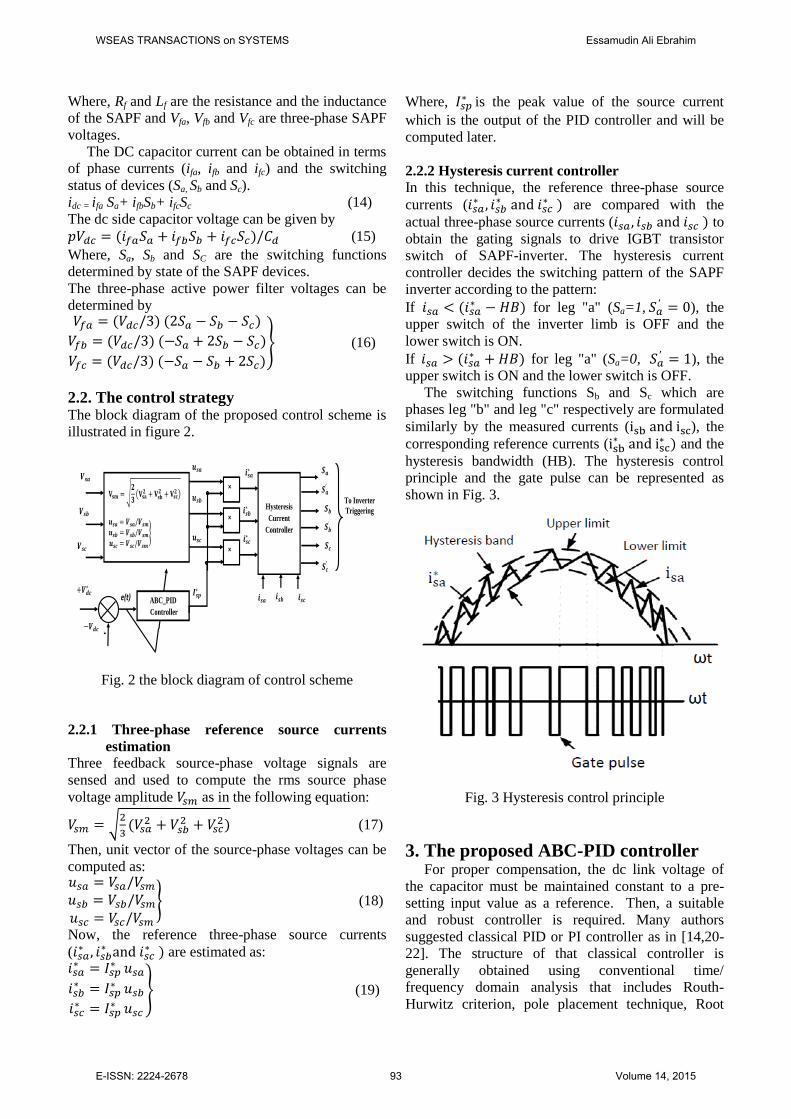
2.2. The control strategy The block diagram of the proposed control scheme is
illustrated in figure 2.
𝒊𝒔𝒄∗
𝒊𝒔𝒃∗
𝒊𝒔𝒂∗
e(t)
𝒖𝒔𝒄
𝒖𝒔𝒃
𝒖𝒔𝒂
𝑰𝒔𝒑∗
+
+
+
+𝑽𝒅𝒄∗
𝑽𝒅𝒄
𝑽𝒔𝒂
𝑽𝒔𝒃
𝑽𝒔𝒄
𝐕𝐬𝐦 = 𝟐
𝟑 𝐕𝐬𝐚
𝟐 + 𝐕𝐬𝐛𝟐 + 𝐕𝐬𝐜
𝟐
𝒖𝒔𝒂 = 𝑽𝒔𝒂/𝑽𝒔𝒎
𝒖𝒔𝒃 = 𝑽𝒔𝒃/𝑽𝒔𝒎
𝒖𝒔𝒄 = 𝑽𝒔𝒄/𝑽𝒔𝒎
ABC_PID
Controller
×
×
×
𝒊𝒔𝒄 𝒊𝒔𝒂 𝒊𝒔𝒃
Hysteresis
Current
Controller
To Inverter
Triggering
𝑺𝒄′
𝑺𝒃′
𝑺𝒄
𝑺𝒂′
𝑺𝒂
𝑺𝒃
Fig. 2 the block diagram of control scheme
2.2.1 Three-phase reference source currents
estimation
Three feedback source-phase voltage signals are
sensed and used to compute the rms source phase
voltage amplitude as in the following equation:
√
(
) (17)
Then, unit vector of the source-phase voltages can be
computed as:
(18)
Now, the reference three-phase source currents
( ∗
∗ ∗ ) are estimated as:
∗
∗
∗
∗
∗
∗
(19)
Where, ∗ is the peak value of the source current
which is the output of the PID controller and will be
computed later.
2.2.2 Hysteresis current controller
In this technique, the reference three-phase source
currents ( ∗
∗ ∗ ) are compared with the
actual three-phase source currents ( ) to
obtain the gating signals to drive IGBT transistor
switch of SAPF-inverter. The hysteresis current
controller decides the switching pattern of the SAPF
inverter according to the pattern:
If ( ∗ ) for leg "a" (Sa=1,
), the
upper switch of the inverter limb is OFF and the
lower switch is ON.
If ( ∗ ) for leg "a" (Sa=0,
), the
upper switch is ON and the lower switch is OFF.
The switching functions Sb and Sc which are
phases leg "b" and leg "c" respectively are formulated
similarly by the measured currents ( ), the
corresponding reference currents ( ∗
∗ ) and the
hysteresis bandwidth (HB). The hysteresis control
principle and the gate pulse can be represented as
shown in Fig. 3.
Fig. 3 Hysteresis control principle
3. The proposed ABC-PID controller For proper compensation, the dc link voltage of
the capacitor must be maintained constant to a pre-
setting input value as a reference. Then, a suitable
and robust controller is required. Many authors
suggested classical PID or PI controller as in [14,20-
22]. The structure of that classical controller is
generally obtained using conventional time/
frequency domain analysis that includes Routh-
Hurwitz criterion, pole placement technique, Root
WSEAS TRANSACTIONS on SYSTEMS Essamudin Ali Ebrahim
E-ISSN: 2224-2678 93 Volume 14, 2015
locus method and Ziegler-Nichols tuning formula.
Among existing tuning techniques, the Ziegler and
Nichols tuning method is mostly used to compute PID
gains for the plant. To achieve optimization for
controller gains , objective function is
determined.
The proposed algorithm depends on the foraging
behavior of a colony of honey bees in nature. It is
called an ABC-PID controller.
All the particles of populations are decoded
for .
3.1 Formulation of objective function The controller design is first redrafted as an
optimization problem where the objective function
comprises time response specifications as steady-state
speed error ( ), which largely depend on controller
parameters. Here, the design task is to minimize
so this can be performed as an optimization problem
by using the following objective function:
dttetITAEJ ))((
0
*
(20)
Where, ( ) ∗ (21)
∗
Minimize J:
Subject to the constraint: Where represents .
3.2 Artificial Bee Colony (ABC) optimization ABC as an optimization tool that provides a
population based search procedure, in which
individuals called food positions are modified by the
artificial bees with time and the bees' aim is to
discover the places of food sources with high nectar
amount and finally the one with highest nectar.
In ABC system, artificial bee fly around in a multi-
dimensional search space and some employed and
onlooker bees choose food source depending on the
experience of themselves and their nest mates, and
adjust their positions. Some scouts bees fly and
choose the food sources randomly without using
experience. If the nectar amount of a new source is
higher than that of the previous one in their memory,
they memorize the new position and forget the
previous one.
In ABC model, the colony consists of three groups
of bees: employed, onlookers and scouts. It is
assumed that there is only one artificial employed bee
for each food source. In other words, the number of
employed bees in the colony is equal to the number of
food sources around the hive. The employed bees go
to their food source and come back to hive and dance
on this area. The employed bee whose food source
has been abandoned becomes a scout and starts
searching a new food source. Onlookers watch the
dances of employed bees and choose food sources
depending on the dances [32,33].
3.3 Pseudo-codes of the ABC algorithm 1. Load samples of controller parameters
2. Generate the initial population FSiXi
,....2,1,
3. Evaluate the fitness ( ) of the population
4. Set cycle to 1
5. Repeat
6. For each employed bee Produce new solution
by using eqn. (24). Calculate the value ( ) by
using eqn. (23).Apply greedy selection process
7. Calculate the probability values ( ) for the
solutions ( ) by eqn. (22)
8. For each onlooker bee Select a solution
depending on Produce new solution
Calculate the value Apply greedy selection
process
9. If there is an abandoned solution for the scout.
Then replace it with a new solution which will be
randomly produced by (25)
10. Memorize the best solution so far
11. cycle= cycle+1
12. Until cycle=MCN
Where, represents a solution, is the fitness
value of , indicates a neighbor solution of ,
the probability value of and MCN is the
maximum cycle numbers in the algorithm.
3.4 Detailed explanation for the algorithm In the algorithm, first half of the colony consists of
employed artificial bees and the second half
constitutes the onlookers. The number of employed
bees is equal to the number of food sources (# of
solutions in the population).
At first step, the algorithm starts by initializing all
employed bees with randomly generated food sources
(solutions), where SN denotes the size of population.
Each solution FSixi
,....2,1, is a D-dimensional
vector. Where D is the number of optimization
parameters. Here, in this study, D- represents the PID-
controller parameters to be optimized.
i.e., After initialization, in each iteration of all given
cycles, every employed bee finds a food source
neighbourhood of its current food source and
evaluates its nectar amount, i.e. fitness). In general the
position of food source is represented as:
( ).
WSEAS TRANSACTIONS on SYSTEMS Essamudin Ali Ebrahim
E-ISSN: 2224-2678 94 Volume 14, 2015
After the information is shared by the employed bees,
onlooker bees go to the region of food source at
based on the probability determined as:
∑
(22)
Where, FS is total number of food sources. Fitness
value is calculated using:
( ) (23)
Here, ( ) is the objective function (J), in this study,
an objective function ITAE determined from
equations (20,21). The onlooker finds its food source
in the region of by using the following equation:
∗ ( ) (24)
Where, ( ) such that ik and
( ) are randomly chosen indexes, r is a
uniformly distributed random number in the range
[-1,1].
If the obtained new fitness value is better than the
fitness value achieved so far, then the bee moves to
this new food source leaving this old one otherwise it
retains its old food source. When all employed bees
have completed this process, the information is shared
with onlookers. Each of the onlookers selects food
source according to probability given above. By this
scheme, good sources are well accommodated with
onlookers than the bad ones. Each bee will search for
a better food source for certain number of cycles
(limit), and if fitness value doesn’t improve then that
particular bee becomes scout bee. In ABC, this is
simulated by producing a position of scout bees
randomly and replacing it with the abandoned one.
Providing that a position cannot be improved further
through a predetermined of cycles, then that food
source is assumed to be abandoned. The value of
predetermined number of cycles is an important
control parameter of the ABC algorithm, which is
called “limit” for abandonment. Assume that the
abandoned source is and , then the
scout discovers a new food source to be replaced
by . This operation can be expressed in the
following relation [37]:
( )(
) (25)
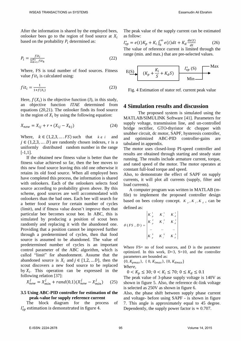
3.5 Using ABC-PID controller for estimation of the
peak-value for supply reference current
The block diagram for the process of
∗
The peak value of the supply current can be estimated
as follow:
∗ ( ) ∫ ( )
( )
(26)
The value of reference current is limited through the
range (min. and max.) that are pre-selected values.
Fig. 4 Estimation of stator ref. current peak value
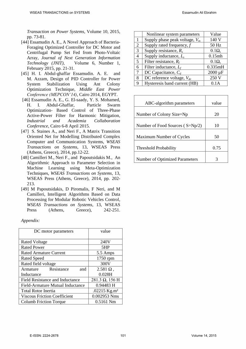
4 Simulation results and discussion The proposed system is simulated using the
MATLAB/SIMULINK Software [41]. Parameters for
supply voltage, transmission line, and un-controlled
bridge rectifier, GTO-thyristor dc chopper with
snubber circuit, dc motor, SAPF, hysteresis controller,
and optimized ABC-PID controller-gains are
tabulated in appendix.
The motor uses closed-loop PI-speed controller and
results are obtained through starting and steady state
running. The results include armature current, torque,
and rated speed of the motor. The motor operates at
constant full-load torque and speed.
Also, to demonstrate the effect of SAPF on supply
currents, it will plot all currents (supply, filter and
load currents).
A computer program was written in MATLAB (m-
file) to implement the proposed controller design
based on bees colony concept. dip
KKK ,, , can be
defined as:
S
d
S
i
S
p
dip
dip
KKK
KKK
KKK
DFS......
),(
222
111
Where FS= no of food sources, and D is the parameter
optimized. In this work, D=3, S=10, and the controller
parameters are bounded as: 0, , 0, , 0,
Where,
; ;
The peak value of 3-phase supply voltage is 140V as
shown in figure 5. Also, the reference dc-link voltage
is selected as 250V as shown in figure 6.
Also, the phase shift between supply phase current
and voltage- before using SAPF - is shown in figure
7. This angle is approximately equal to 45 degree.
Dependently, the supply power factor is 0.707.
∗ (S)
Min
Max
E(S) (
)
WSEAS TRANSACTIONS on SYSTEMS Essamudin Ali Ebrahim
E-ISSN: 2224-2678 95 Volume 14, 2015
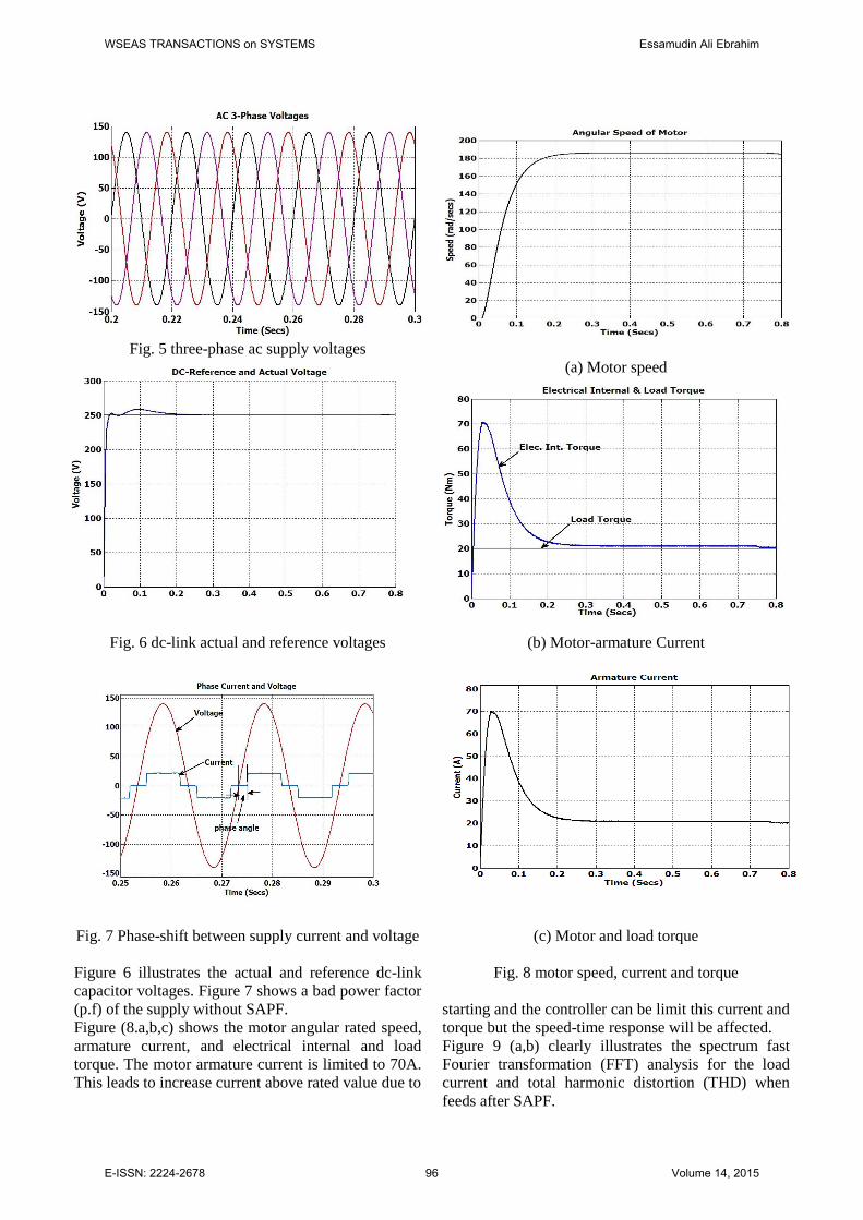
Fig. 5 three-phase ac supply voltages
Fig. 6 dc-link actual and reference voltages
Fig. 7 Phase-shift between supply current and voltage
Figure 6 illustrates the actual and reference dc-link
capacitor voltages. Figure 7 shows a bad power factor
(p.f) of the supply without SAPF.
Figure (8.a,b,c) shows the motor angular rated speed,
armature current, and electrical internal and load
torque. The motor armature current is limited to 70A.
This leads to increase current above rated value due to
(a) Motor speed
(b) Motor-armature Current
(c) Motor and load torque
Fig. 8 motor speed, current and torque
starting and the controller can be limit this current and
torque but the speed-time response will be affected.
Figure 9 (a,b) clearly illustrates the spectrum fast
Fourier transformation (FFT) analysis for the load
current and total harmonic distortion (THD) when
feeds after SAPF.
WSEAS TRANSACTIONS on SYSTEMS Essamudin Ali Ebrahim
E-ISSN: 2224-2678 96 Volume 14, 2015
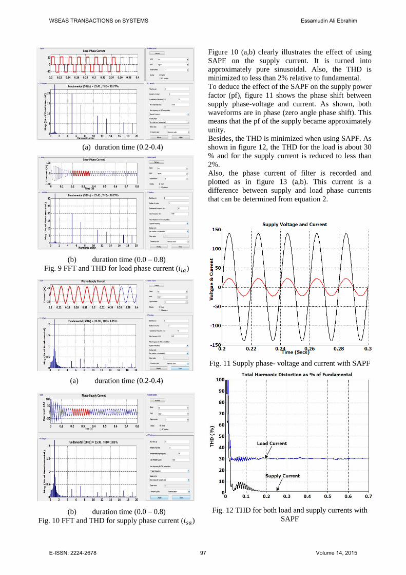
(a) duration time (0.2-0.4)
(b) duration time (0.0 – 0.8)
Fig. 9 FFT and THD for load phase current ( )
(a) duration time (0.2-0.4)
(b) duration time (0.0 – 0.8)
Fig. 10 FFT and THD for supply phase current ( )
Figure 10 (a,b) clearly illustrates the effect of using
SAPF on the supply current. It is turned into
approximately pure sinusoidal. Also, the THD is
minimized to less than 2% relative to fundamental.
To deduce the effect of the SAPF on the supply power
factor (pf), figure 11 shows the phase shift between
supply phase-voltage and current. As shown, both
waveforms are in phase (zero angle phase shift). This
means that the pf of the supply became approximately
unity.
Besides, the THD is minimized when using SAPF. As
shown in figure 12, the THD for the load is about 30
% and for the supply current is reduced to less than
2%.
Also, the phase current of filter is recorded and
plotted as in figure 13 (a,b). This current is a
difference between supply and load phase currents
that can be determined from equation 2.
Fig. 11 Supply phase- voltage and current with SAPF
Fig. 12 THD for both load and supply currents with
SAPF
WSEAS TRANSACTIONS on SYSTEMS Essamudin Ali Ebrahim
E-ISSN: 2224-2678 97 Volume 14, 2015
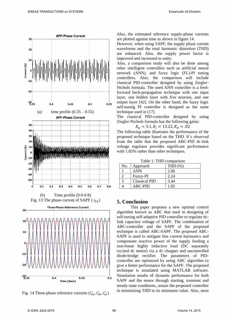
(a) time profile (0.35 – 0.55)
(b) Time profile (0.0-0.8)
Fig. 13 The phase-current of SAPF ( )
Fig. 14 Three-phase reference currents ( ∗
∗ ∗ )
Also, the estimated reference supply-phase currents
are plotted against time as shown in figure 14.
However, when using SAPF, the supply phase current
waveforms and the total harmonic distortion (THD)
are enhanced. Also, the supply power factor is
improved and increased to unity.
Also, a comparison study will also be done among
other intelligent controllers such as artificial neural
network (ANN), and fuzzy logic (FL)-PI tuning
controllers. Also, the comparison will include
classical PID-controller designed by using Ziegler-
Nichols formula. The used ANN controller is a feed-
forward beck-propagation technique with one input
layer, one hidden layer with five neurons, and one
output layer [42]. On the other hand, the fuzzy logic
self-tuning PI controller is designed as the same
technique used in [17].
The classical PID-controller designed by using
Ziegler-Nichols formula has the following gains:
The following table illustrates the performance of the
proposed technique based on the THD. It’s observed
from the table that the proposed ABC-PID dc-link
voltage regulator provides significant performance
with 1.85% rather than other techniques.
Table 1: THD comparison
No. Approach THD (%)
1 ANN 2.06
2 Fuzzy-PI 2.24
3 Classical PID 3.44
4 ABC-PID 1.85
5. Conclusion This paper proposes a new optimal control
algorithm known as ABC that used in designing of
self-tuning self-adaptive PID controller to regulate dc-
link capacitor voltage of SAPF. The combination of
ABC-controller and the SAPF of the proposed
technique is called ABC-SAPF. The proposed ABC-
SAPF is used to mitigate line current harmonics and
compensate reactive power of the supply feeding a
non-linear highly inductive load (DC separately
excited dc motor) via a dc chopper and uncontrolled
diode-bridge rectifier. The parameters of PID-
controller are optimized by using ABC algorithm to
give a better performance for the SAPF. The proposed
technique is simulated using MATLAB software.
Simulation results of dynamic performance for both
SAPF and the motor through starting, transient and
steady-state conditions, assure the proposed controller
in minimizing THD to its minimum value. Also, most
WSEAS TRANSACTIONS on SYSTEMS Essamudin Ali Ebrahim
E-ISSN: 2224-2678 98 Volume 14, 2015
of harmonics are mitigated and the supply power
factor (p.f.) is increased to approximately unity. In
addition, the performance of that proposed approach
is compared with other control strategies such as
classical PID, fuzzy-PI, and ANN controllers.
However, these results validate the superiority of the
proposed method in tuning process compared with
other mentioned controllers.
References:
[1] C. Broche et al, Harmonic Reduction in DC by
Active Filtering, IEEE Transactions on Power
Electronics, Vol. 7, NO. 4, Oct. 1992, pp. 633-
643.
[2] J. Talla and V. Blahník, Single-Phase Filtering
System for DC Motor Locomotives, International
Conference on Clean electrical Power (ICCEP),
2013, pp. 712-716.
[3] S. Bhattacharya et al., Flux Based Active Filter
Controller, IEEE Transactions on Industry
Applications, Volume 32, Issue 3, 1996, pp. 491-
502.
[4] Hirofumi Akagi, New Trends in Active Filters for
Improving Power Quality, 1996., Proceedings of
the 1996 International Conference on
Power Electronics, Drives and Energy Systems for
Industrial Growth, 1996, vol. 1, pp. 417-425.
[5] B.Singh,K. Al-Haddad and A.Chandra, A New
Control Approach to Three-phase Active Filter for
Harmonics and Reactive Power Compensation,
IEEE Transactions on Power Systems, Vol. 13,
No. 1, February 1998, pp. 133-138.
[6] IEEE Recommended Practice and Requirements
for Harmonic Control in Electric Power Systems,
IEEE Std 519-2014 (Revision of IEEE Std 519-
1992), 2014, pp. 1-29.
[7] Electromagnetic compatibility (EMC). Limits.
Limits for harmonic current emissions (equipment
input current ≤ 16 A per phase), BS EN 61000-3-
2, Sept.2014.
[8] H. Akagi et al, A Shunt Active Filter Based on
Voltage Detection for Harmonic Termination of a
Radial Power Distribution Line, IEEE
Transactions on Industry Applications, Volume
35, Issue 3, 1999, pp. 638-645.
[9] H. Akagi, Active and Hybrid Filters for Power
Conditioning, Proceedings of the 2000 IEEE
International Symposium on Industrial
Electronics, 2000. ISIE 2000.4-8 Dec. 2000, Cholula, Puebla, Mexico, pp. 26-36, vol. 1.
[10] M. Montero, E. Cadaval and F. González, Comparison of Control Strategies for Shunt Active
Power Filters in Three-Phase Four-Wire Systems ,
IEEE Transactions on Power Electronics, Vol. 22,
No. 1, Jan. 2007, pp 229-236.
[11] D Kucherenko and P Safronov, A Comparison of
Time Domain Harmonic Detection Methods for
Compensating Currents of Shunt Active Power
Filter, 2014 IEEE International Conference on
Intelligent Energy and Power Systems (IEPS), 2-6
June 2014, Kyiv, Ukraine, pp. 40-45.
[12] S. Biricik et al, Real-Time Control of Shunt
Active Power Filter under Distorted Grid Voltage
and Unbalanced Load Condition using Self-
Tuning Filter, IET Power Electron., 2014, Vol. 7,
Issue 7, pp. 1895–1905.
[13] A.Terciyanli et al, A Current Source Converter -
Based Active Power Filter for Mitigation of
Harmonics at the Interface of Distribution and
Transmission Systems, IEEE Transactions on
Industry Applications, Volume 48, Issue 4, 2012,
pp. 1374-1386
[14] Q.Trinh and H. Lee, An Advanced Current
Control Strategy for Three-Phase Shunt Active
Power Filters, IEEE Transactions on Industrial
Electronics, Vol. 60, NO. 12, Dec.2013, pp. 5400-
5410.
[15] M. Sindhu, M. Nair and T. Nambiar, Dynamic
Power Quality Compensator with an Adaptive
Shunt Hybrid Filter, Int. Journal of Power
Electronics and Drive System (IJPEDS), Vol. 4,
No. 4, Dec. 214, pp 508-516.
[16] M. Qasim, P. Kanjiya, and V. Khadkikar,
Artificial-Neural-Network-Based Phase-Locking
Scheme for Active Power Filters, IEEE
Transactions on Industrial Electronics, Vol. 61,
No. 8, Aug. 2014, pp. 3857-3866.
[17] Y. Suresh A.K. Panda M. Suresh, Real-Time
Implementation of Adaptive Fuzzy Hysteresis-
Band Current Control technique for Shunt Active
Power Filter, IET Power Electron., Vol. 5, Issue 7,
2012, pp. 1188–1195.
[18] N. Eskandarian, Y. Beromi, and S. Farhangi ,
Improvement of Dynamic Behavior of Shunt
Active Power Filter Using Fuzzy Instantaneous
Power Theory, Journal of Power Electronics,
Vol. 14, No. 6, pp. 1303-1313, November 2014,
pp. 1303-1312.
[19] L. Saribulut1, A.Teke, and M. Tüma, Artificial
Neural Network-Based Discrete-Fuzzy Logic
Controlled Active Power Filter, IET Power
Electronics, 2014, Vol. 7, Issue 6, pp. 1536–1546.
[20] S.Suresh and S.Kannan, DC Link Voltage
Regulated Active Power Line Conditioner for
Compensating Harmonic and Reactive Power,
2011 International Conference on Recent
Advancements in Electrical, Electronics and
WSEAS TRANSACTIONS on SYSTEMS Essamudin Ali Ebrahim
E-ISSN: 2224-2678 99 Volume 14, 2015
Control Engineering, 15-17 Sep. 2011, College
Sivakasi , India, pp. 87-90.
[21] S. Rahmani et al, A Combination of Shunt
Hybrid Power Filter and Thyristor-Controlled
Reactor for Power Quality, IEEE Transactions on
Industrial Electronics, Vol. 61, No. 5, May. 2014,
pp. 2152-2164.
[22] S. Biricik et al, Real-Time Control of Shunt
Active Power Filter Under Distorted Grid Voltage
and Unbalanced Load Condition using Self-
Tuning Filter, IET Power Electronics, 2014, Vol.
7, Issue 7, pp. 1895–1905.
[23] R.Ribeiro, C. Azevedo, and R. M. Sousa, A
Robust Adaptive Control Strategy of Active Power
Filters for Power-Factor Correction, Harmonic
Compensation, and Balancing of Non -linear
Loads, IEEE Transactions on Power Electronics,
Vol. 27, NO. 2, Feb. 2012, pp. 718-730.
[24] R.Ribeiro, T. Rocha, and R. M. Sousa, A Robust
DC-Link Voltage Control Strategy to Enhance the
Performance of Shunt Active Power Filters
without Harmonic Detection Schemes, IEEE
Transactions on Industrial Electronics, 2013,
Citation information: DOI 10.1109 / TIE. 2014.
2345329.
[25] B. Angélico, L. Campanhol, and S. Silva,
Proportional – Integral / Proportional–Integral
Derivative Tuning Procedure of a Single-Phase
Shunt Active Power Filter Using Bode Diagram,
IET Power Electronics, 2014, Vol. 7, Issue 10, pp.
2647–2659.
[26] Sreeraj E. S. et al, An Active Harmonic Filter
Based on One-Cycle Control, IEEE Transactions
on Industrial Electronics, Vol. 61, No. 8, Aug.
2014, pp. 3709-3809.
[27] L. Yang, A Stable Self-Learning PID Control
Based on the Artificial Immune Algorithm, Proc.
of the IEEE Inter. Conf. on Automation and
Logistics, Shenyang, China, Aug. 2008, pp. 1237-
1242.
[28] Q. Zeng and G. Tan, Optimal Design of PID
Controller using Modified Ant Colony System
Algorithm", IEEE Third Int. Conf. on Natural
Computation (ICNC'07), 24-27Aug. 2007, China
[29] H. I. Abdul-ghaffar Essamudin. A. E. and
M. Azzam, Design of PID Controller for Power
System Stabilization Using Hybrid Particle
Swarm-Bacteria Foraging Optimization, WSEAS
Transaction on Power Systems, Issue 1, Volume 8,
January 2013, pp. 12-23.
[30] A. S. Oshaba and E. S. Ali, Bacteria Foraging: A
New Technique for Speed Control of DC Series
Motor Supplied by Photovoltaic System, WSEAS
Transaction on Power Systems, Volume 9, 2014,
pp. 185-195.
[31] P. Saravanan and P. Balakrishnan, An
Efficient BFO Algorithm for Self Tuning Pi-
Controller Parameters for Shunt Active Power
Filter, WSEAS Transaction on Power Systems,
Volume 9, 2014, pp. 155-170.
[32] Darvis. Karaboga, An Idea Based on Honey Bee
Swarm for Numerical Optimization Technique,
Report‐06, Erciyes University Engineering
Faculty, Computer Engineering Department 2005.
[33] B. Basturk, D. Karaboga, An Artificial Bee
Colony (ABC) Algorithm for Numeric Function
Optimization, IEEE Swarm Intelligence
Symposium 2006, Indianapolis, Indiana,
USA,2006.
[34] N. Elkhateeb and R. Badr, Employing Artificial
Bee Colony with Dynamic Inertia Weight for
Optimal Tuning of PID Controller, U2013
Proceedings of Int. Conf. On Modelling,
Identification & control (ICMIC), Cairo, Egypt,
31th Aug. – 2nd
Sep. 2013, pp. 42-46.
[35] A. Rahim, M. Ali, Tuning of PID SSSC
Controller Using Artificial Bee Colony
Optimization Technique, 2014 11th International
Multi-Conference on Systems, Signals & Devices ,
11-14 Feb 2014, Barcelona, Spain, pp. 1-6.
[36] W. Liao, Y. Hu, and H. Wang, Optimization of
PID Control for DC Motor Based on Artificial Bee
Colony Optimization, Proceedings of the 2014 Int.
Conf. on Advanced Mechatronics Systems,
Kumamoto , Japan, 10-12 Aug., 2014, pp. 23-27.
[37] Essamudin A. E., “Artificial Bee Colony-Based
Design of Optimal On-Line Self-tuning PID-
Controller Fed AC Drives”, International Journal
of Engineering Research (IJER), Vol. No.3, Issue
No.12, 1 Dec. 2014, pp. 807-811.
[38] P. Pejovic, Three-Phase Diode Rectifiers with
Low Harmonics, Book chapter 2, Springer
Publishing, 2007.
[39] J. Arrillaga and N. R. Watson, Power System
Harmonics, 2nd
Edition, John Wiley & sons, USA
, 2004.
[40] Bill Drury, The Control Technique Drives and
Controls, Handbook, IEE Power and Energy
Series 35, The Institute of Electrical Engineers,
London, UK, 2001.
[41] Mathwork Co., “MATLAB Software Manual”,
USA 2014.
[42] Essamudin A. E., Artificial Neural Network-
Based Tracking Adaptive Vector-Control of Three-
Phase Induction-Motor Servo-Drives, Ph.D.
thesis, Cairo University, 2001.
[43] G. El-Saady, A. El-Sayed, Essamudin A. E., and
H. I. Abdul-Ghaffar, Harmonic Compensation
Using On-Line Bacterial Foraging Optimization
Based Three-Phase Active Power Filter, WSEAS
WSEAS TRANSACTIONS on SYSTEMS Essamudin Ali Ebrahim
E-ISSN: 2224-2678 100 Volume 14, 2015
Transaction on Power Systems, Volume 10, 2015,
pp. 73-81.
[44] Essamudin A. E., A Novel Approach of Bacteria-
Foraging Optimized Controller for DC Motor and
Centrifugal Pump Set Fed from Photo-Voltaic
Array, Journal of Next Generation Information
Technology (JNIT), Volume 6, Number 1,
February 2015, pp. 21-31.
[45] H. I. Abdul-ghaffar Essamudin. A. E. and
M. Azzam, Design of PID Controller for Power
System Stabilization Using Ant Colony
Optimization Technique, Middle East Power
Conference (MEPCON’14), Cairo 2014, EGYPT.
[46] Essamudin A. E., G. El-saady, Y. S. Mohamed,
H. I. Abdul-Ghaffar, Particle Swarm
Optimization- Based Control of Three-Phase
Active-Power Filter for Harmonic Mitigation,
Industrial and Academia Collaboration
Conference, Cairo 6-8 April 2015.
[47] S. Staines A., and Neri F., A Matrix Transition
Oriented Net for Modelling Distributed Complex
Computer and Communication Systems, WSEAS
Transactions on Systems, 13, WSEAS Press
(Athens, Greece), 2014, pp.12-22.
[48] Camilleri M., Neri F., and Papoutsidakis M., An
Algorithmic Approach to Parameter Selection in
Machine Learning using Meta-Optimization
Techniques, WSEAS Transactions on Systems, 13,
WSEAS Press (Athens, Greece), 2014, pp. 202-
213.
[49] M Papoutsidakis, D Piromalis, F Neri, and M
Camilleri, Intelligent Algorithms Based on Data
Processing for Modular Robotic Vehicles Control,
WSEAS Transactions on Systems, 13, WSEAS
Press (Athens, Greece), 242-251.
Appendix:
DC motor parameters
value
Rated Voltage 240V
Rated Power 5HP
Rated Armature Current 5.5 Amps
Rated Speed 1750 rpm
Rated field voltage 300V
Armature Resistance and
Inductance
2.581 Ω ,
0.028H
Field Resistance and Inductance 281.3 Ω, 156 H
Field-Armature Mutual Inductance 0.94483 H
Total Rotor Inertia .02215 Kg.m²
Viscous Friction Coefficient 0.002953 Nms
Columb Friction Torque 0.5161 Nm
Nonlinear system parameters Value
1 Supply phase peak voltage, Vm 140 V
2 Supply rated frequency, f 50 Hz
3 Supply resistance, Rs 0.1Ω,
4 Supply inductance, Ls 0.15mh
5 Filter resistance, Rf 0.1Ω,
6 Filter inductance, Lf 0.335mH
7 DC Capacitance, Cd 2000 µF
8 DC reference voltage, Vdc 250 V
9 Hysteresis band current (HB) 0.1A
ABC-algorithm parameters value
Number of Colony Size=Np 20
Number of Food Sources ( S=Np/2) 10
Maximum Number of Cycles 50
Threshold Probability 0.75
Number of Optimized Parameters 3
WSEAS TRANSACTIONS on SYSTEMS Essamudin Ali Ebrahim
E-ISSN: 2224-2678 101 Volume 14, 2015