Power Quality Enhancement Through Robust Symmetrical...
26
Chapter 3 Power Quality Enhancement Through Robust Symmetrical Components Estimation in Weak Grids António Pina Martins Additional information is available at the end of the chapter http://dx.doi.org/10.5772/53138 1. Introduction Power conditioning systems like active filters, universal power flow controllers, static compensators, and dynamic voltage restorers need accurate control and synchronization circuits capable of dealing with very different grid voltage perturbations. Phasor estima‐ tion and symmetrical components estimation is a fundamental task in power systems re‐ laying and power quality characterization. Voltage sags and swells, harmonics, frequency variation, phase steps, DC components and noise, are phenomena that can cause severe malfunction in the control or supervision circuits of such power systems. Additionally, they must be identified, measured and quantified for power quality purposes. More‐ over, some protection systems are sensitive to these parameters and can develop errone‐ ous actions. Instantaneous symmetrical components, required for power quality analysis and power electronics converter control, are robust estimated by the Discrete Fourier Transform algorithm in normal conditions. However, strong grid voltage perturbations, occurring in weak grids, especially in the grid connection of renewable energies, are more challenging. The chapter accurately describes the DFT errors under frequency var‐ iation, decaying DC components and harmonics. The error analysis allows the extension of the DFT algorithm to manage these known but more frequent and severe phenom‐ ena. The method is capable of handling a large variety of grid voltage perturbations, maintaining a good dynamic response and accuracy. These are the main reasons why the DFT algorithm is widely used in Phasor Measurement Units (PMUs) and power quality analyzers [1-2]. © 2013 Pina Martins; licensee InTech. This is an open access article distributed under the terms of the Creative Commons Attribution License (http://creativecommons.org/licenses/by/3.0), which permits unrestricted use, distribution, and reproduction in any medium, provided the original work is properly cited.
Transcript of Power Quality Enhancement Through Robust Symmetrical...

Chapter 3
Power Quality EnhancementThrough Robust Symmetrical ComponentsEstimation in Weak Grids
António Pina Martins
Additional information is available at the end of the chapter
http://dx.doi.org/10.5772/53138
1. Introduction
Power conditioning systems like active filters, universal power flow controllers, staticcompensators, and dynamic voltage restorers need accurate control and synchronizationcircuits capable of dealing with very different grid voltage perturbations. Phasor estima‐tion and symmetrical components estimation is a fundamental task in power systems re‐laying and power quality characterization. Voltage sags and swells, harmonics, frequencyvariation, phase steps, DC components and noise, are phenomena that can cause severemalfunction in the control or supervision circuits of such power systems. Additionally,they must be identified, measured and quantified for power quality purposes. More‐over, some protection systems are sensitive to these parameters and can develop errone‐ous actions. Instantaneous symmetrical components, required for power quality analysisand power electronics converter control, are robust estimated by the Discrete FourierTransform algorithm in normal conditions. However, strong grid voltage perturbations,occurring in weak grids, especially in the grid connection of renewable energies, aremore challenging. The chapter accurately describes the DFT errors under frequency var‐iation, decaying DC components and harmonics. The error analysis allows the extensionof the DFT algorithm to manage these known but more frequent and severe phenom‐ena. The method is capable of handling a large variety of grid voltage perturbations,maintaining a good dynamic response and accuracy. These are the main reasons why theDFT algorithm is widely used in Phasor Measurement Units (PMUs) and power qualityanalyzers [1-2].
© 2013 Pina Martins; licensee InTech. This is an open access article distributed under the terms of the CreativeCommons Attribution License (http://creativecommons.org/licenses/by/3.0), which permits unrestricted use,distribution, and reproduction in any medium, provided the original work is properly cited.

2. The DFT environment
The Discrete Fourier Transform (DFT) has been widely used in the analysis of the funda‐mental component and harmonics of the electric grid voltages and currents, namely inPMUs and protection relays [3-4]. The temporal information loss caused by the transforma‐tion is recovered by analyzing the signal in just one temporal window with duration of oneor a multiple of the fundamental period of the analyzed waveform. The DFT method givesaccurate results when the sampled period is equal to the fundamental period.
In case of input frequency variations there is a phase shift between the input and output sig‐nals, as well as spectral leakage. With unknown input frequencies the signal components areprojected to the presumed frequency components, multiples of the input frequency. Duringfast transients or faults, the grid voltage is characterized by being a non-periodic signal con‐taining fast oscillations, exponential decaying components and harmonics, among other pos‐sible disturbances. Fundamental component extraction by conventional DFT is affected byan important error due to the limited temporal resolution of the analyzed window.
The phase difference resulting from the difference between the presumed frequency and thereal frequency can be compensated in different ways: by imposing that the analyzed intervalshould be equal to the grid period, [5], or by adding a phase offset to cancel the phase differ‐ence. The second method is preferable since it does not imply a change in the execution fre‐quency of the digital algorithm that can be embedded in control task with other algorithms thatneed to be executed at a fixed frequency. The so-called Smart Discrete Fourier Transform, [6],measures the input phasor signal and estimates the frequency with high precision, superior tothe conventional DFT, showing robustness and being implemented in a recursive manner. Theestimation precision is robust in the presence of noise and is higher if it is considered high or‐der harmonics but implying a more complex algorithm and pre filtering, [7].
Different methods have been proposed to allow the DFT algorithm to deal with variable fre‐quency input signals, exponential decaying components and noise immunity. Adaptive var‐iation of the temporal window, adaptive change of the sampling frequency, phase andamplitude correction and input data modification are the main proposed methods to in‐crease the DFT algorithm performance.
Input low pass anti-aliasing filters can eliminate the high frequency components but can notremove decaying dc components and reject low frequency components. Under these condi‐tions, the DFT-based phasor estimation is more difficult and slower and affects the perform‐ance of converters synchronization and digital relaying.
Absolute and recursive DFT modified algorithms can be applied to some of the above men‐tioned non-nominal operating conditions. However, a more realistic list of abnormal fieldoperating conditions includes:
Amplitude variation (sags and swells). If voltage swells are important because they cancause serious damage in electrical machines and transformers voltage sags are becomingmore demanding since there is a need to maintain some important grid connected system inoperation even under high amplitude sags, [8].
Power Quality Issues68

Harmonics. The presence of high power nonlinear loads, deregulation rules and increasedpower flow allowed the increase of harmonics presence in the grid voltage.
Spikes and notches. Caused by power devices switching and capacitors commutation theycan severely affect zero crossing detection and generate low frequency harmonics.
Frequency variation (step and continuous). High active power variations, generators failureand power transfers between large connected areas can cause frequency variations. As volt‐age sags, frequency deviations from the nominal value are imposing new and demandingconditions in the new energy generation era.
Phase steps. Connecting and disconnecting large loads, especially in weak grids, are themain origin of phase steps occurrence. Having an extremely large frequency spectrum theycause important transient phenomena as in amplitude measurement or frequency estima‐tion as in control systems.
Exponential decaying components. Generated by different fault types or grid connection ofhigh power electrical machines they constitute with phase steps the more important distur‐bances that appear in a grid voltage system.
Noise. Always present and generated by very different sources.
Phasor estimation under different grid voltage perturbations and symmetrical componentscalculation for power conditioning converters control are the parameters to be analyzed inthe chapter. Performance optimization for the all conditions should be a compromise.
3. Symmetrical components estimation with the DFT
Apart from noise and harmonics, which will be considered later, the main components of avoltage signal from the phasor detection point of view can be expressed as:
/( ) cos( ) tx t X t Ae tw j -= + + (1)
where A is the initial amplitude of a decaying DC component being τ its time constant, X isthe amplitude of the voltage signal, ω the fundamental frequency, and ϕ the phase angle ofthe voltage signal.
Assume that x(t) is sampled at a sampling rate fs, multiple of the nominal frequency, fo:
1s o
sf f N
T= = (2)
Being fo the nominal frequency and N the number of samples per fundamental nominal peri‐od, the sampling produces a data sequence x(kTs), or x(k):
Power Quality Enhancement Through Robust Symmetrical Components Estimation in Weak Gridshttp://dx.doi.org/10.5772/53138
69

/( ) cos skT
o
kx k X Aef N
tw j -æ ö= + +ç ÷ç ÷
è ø(3)
Using a phasor representation with
cos sinjx Xe X jXj j j= = + (4)
The signal x(k) can be represented by
/( )2
k ks
j t j tkTxe x ex k Ae
w wt
--
*+
= + (5)
where * denotes complex conjugate. The fundamental frequency component, X1, (at instant kand with nominal frequency, f=fo) given by the DFT algorithm is
1 21
0
2( ) ( )N f iTo s
iX k x k i N e
Np- -
== + -å (6)
It is important to note that at instant k, the data window used to compute the DFT goes fromk-N to k-1. Taken frequency variation, f=fo+Δf, into consideration and substituting the signalphasor representation in the DFT expression, the fundamental component is
2 22 ( ) 2 ( )1 1
10 0
21
0
( )
2
k i N k i Nj f f j f fN No j i o j if N f No N o N
i ik i N
N j if No N
i
x xX k e e e eN N
A e eN
p pp p
pt
+ - + -+D - +D- -- -
= =+ -
-- -
=
*= × + ×
+ ×
å å
å(7)
With some algebraic manipulation, the expression can be given by
2 2(2 1) (2 1)( 1)1 21
1 21
1 2
sin( ) sin( )( )
sin( ) sin( )
2 1
1
f fj k N j k Nj k j kN f N fN o N o
kfo f Noj
f N No
N Nx xX k e e e eN N
A e eN
e
p pp p
tt
pt
q qq q
D D- - - - -- -
-
- -
*= × × + × ×
-- × ×
-
(8)
Power Quality Issues70

The frequency deviation dependent angles θ1 and θ2 are given by
1 2; 2o o
f fN f N fp pq q
æ öD D= = +ç ÷ç ÷
è ø(9)
Harmonics presence in the grid voltage when there is a frequency deviation creates addi‐tional errors. It can be shown that the existence of m harmonics causes an error in the funda‐mental component that is given by:
(1 )(2 1) 13
13
1, 1
sin( )1( )sin( )
o
fj h k N Nm j N fhh
h mh
NX k X e e
N
pj q
q
é ùD+ - - - +ê ú
ê úë û
=-¹- +
D = × ×å (10)
where
3 1o
fh hN fpqæ öD
= - +ç ÷ç ÷è ø
(11)
Eq. (8) and (10) clearly show the behaviour of the DFT algorithm under abnormal condi‐tions. In what respects to frequency deviation the resulting fundamental component has twotypes of errors: amplitude and phase. The positive direction rotating phasor presents a fre‐quency deviation dependent amplitude and phase; the negative direction rotating phasorhas also variable amplitude and rotates at a double frequency. Harmonics have a similar butmuch smaller contribution to the referred errors. The presence of an exponential decay com‐ponent introduces a complex error, very unfavourable in phasor detection.
The DFT algorithm with these two conditions, variable frequency and exponential compo‐nent, can be used if the resulting errors are correctly handled.
3.1. Correction for variable frequency
There are some approaches to variable frequency operation: analytical correction based onabsolute DFT calculation [6, 9], recursive DFT algorithm [5, 10-11], and high frequency filter‐ing [12].
In [9], frequency estimation is based on the phase variation given by two DFT calculationsand approximate expressions so containing a frequency deviation dependent error. Themethod presented in [6] is simple in ideal conditions and can be recursive, but is susceptibleto harmonics; its consideration highly increases the method complexity. Recursive DFT ap‐proaches share the same initial simplicity. When dealing with variable frequency the correc‐tion methods are very different, essentially depending on the measurement purpose.
Power Quality Enhancement Through Robust Symmetrical Components Estimation in Weak Gridshttp://dx.doi.org/10.5772/53138
71

In [10] it is analyzed only phase correction, not amplitude, which is important for phasorestimation. Sampling frequency variation, proposed in [5], is not a feasible method; also, lin‐ear correction of the measured phase presents good results but is not tested in all conditions.Recursive DFT calculation with phase and amplitude correction, as presented in [11], workswell. However, DC decaying components cause significant perturbations in phasor estima‐tion. Filtering the high frequency components present in the amplitude and phase values re‐turned by the DFT is limited to small frequency deviations [12]. Also, filtering introduces anadditional delay in the phasor estimation.
In general, it can not be guaranteed the absence of even harmonics, so any method based onthe half cycle DFT is not considered. The relative slower dynamics of the full cycle DFTmust be assumed.
3.2. Decaying DC component compensation
Accurate elimination of the exponentially decaying DC component from the fundamentalphasor calculated by the DFT is treated by different methods: mimic filter [13], input datacorrection [14-15], and analytical calculation with variable data window [16].
The mimic filter just uses an average value of the presumed decay component time constant,amplifies high frequency components and introduces a phase advance in the fundamentalcomponent, so making it unsuitable for accurate instantaneous phasor detection. Also, oper‐ation under variable frequency introduces amplitude errors. Input data correction, so elimi‐nating the decay component, can be made just one cycle after the occurrence of a fault.Naturally, there is a need to detect the fault; the method is tailored for fault occurrence.
The correct fundamental component phasor is only obtained after N samples [15] or N+4samples [17]. Of course, this is much better than the simple DFT algorithm that originates anamplitude overshoot and settling time dependent on the time constant but also is done withhigh complex calculations. In practical applications this complexity results in two very im‐portant aspects: execution time and run time errors, due to trigonometric operations andpossible divide by zero operations or square root calculations, respectively.
The variable data window method in [16] is not so complex and is also fast but does not con‐sider frequency deviation. Additionally, its main algorithm is tailored for fault detection, notfor permanent operation like grid voltage feature extraction or control purposes like syn‐chronization or current control.
3.3. Symmetrical components for power conditioning devices
Single phase phasor estimation and three-phase symmetrical components estimation are avery useful tool in power systems. During unbalanced disturbances their values change sig‐nificantly. Although the symmetrical components concept is a frequency domain one, it isextended to the time domain, [18]. The estimation of symmetrical components from meas‐ured signals can be used for efficient control, supervision and protection in electrical powersystems especially in unbalanced ones [19] or for instantaneous phasor detection [20-21].
Power Quality Issues72

The digital implementation of three-phase symmetrical components is based on two ap‐proaches: by the definition, with the help of a digital time delay, or by the decomposition ofthe three-phase signals in orthogonal components followed by a complex digital filtering[22]. The former is more general and will be used here.
Being va(t), vb(t), and vc(t) three-phase instantaneous voltages the instantaneous symmetricalcomponents are defined by:
0
2
2
( ) 1 1 1 ( )1( ) 1 ( ) 3 ( )( ) 1
a apa bn
ca
v t v tv t a a v t
v tv t a a
é ù é ù é ùê ú ê ú ê úê ú = ×ê ú ê úê ú ê ú ê úë ûê ú ë ûë û
(12)
where a=exp(2π/3).
The instantaneous positive and negative sequence components defined by (12) are in generalcomplex signals. Another definition yielding real signals can be obtained through the substi‐tution of the complex operator a by a 120º phase shift in the time domain as follows:
0
120 240
240 120
( ) ( ) ( ) ( )1( ) ( ) ( ) ( ) 3
( ) ( ) ( )( )
a a b cpa a b bn
a b ca
v t v t v t v tv t v t S v t S v t
v t S v t S v tv t
é ù é ù+ +ê ú ê úê ú = × + +ê úê ú ê ú+ +ë ûê úë û
(13)
The negative sequence instantaneous symmetrical component is of no interest, because it isthe complex conjugate of the positive sequence instantaneous symmetrical component.
Since the DFT algorithm extracts the phasor information, the symmetrical components canbe easily obtained through the phase shift operator and algebraic processing. Furthermore,using only the fundamental component returned by the DFT it can be readily obtained thefundamental positive and negative instantaneous components.
The positive sequence instantaneous component has the following expression:
2
2
2
( ) 1 ( )1( ) 1 ( ) 3
( )1( )
pa apb bp
cc
v t a a v tv t a a v t
v ta av t
é ù é ù é ùê ú ê ú ê úê ú ê ú= × ê úê ú ê ú ê úê ú ë ûê úë ûë û
(14)
The application of the DFT algorithm to extract the symmetrical sequence components wasdiscussed in several works [12, 23-24]. The algorithm, with the appropriate and presentedcounter measures is capable of dealing with non-stationary signals and variable frequency.Symmetrical components estimation in conjunction with amplitude, phase and frequency
Power Quality Enhancement Through Robust Symmetrical Components Estimation in Weak Gridshttp://dx.doi.org/10.5772/53138
73

detection can be made according to the diagram in Figure 1. With the sampling theorem sat‐isfied by fast A/D converters, enough bandwidth is available for fast dynamics, namely forincluding low frequency harmonics detection.
Figure 1. DFT-based three-phase symmetrical components calculation with instantaneous amplitude, phase and fre‐quency estimation.
4. Handling grid perturbations
The proposed method is focussed for power converters control and protection. It is intendedfor operating under all input voltage conditions including the above referred ones. The mostdemanding are the decaying DC components and the frequency variations. With these con‐ditions present it was made an extensive study on the performance of a DFT-based methodfor operating under a general and unknown electrical environment.
Different criteria have been used to assess the performance of a particular method. Opera‐tion in all mandatory conditions must be a compromise between dynamics and precision:dynamics in order to efficiently control the converter currents and correctly measure the am‐plitude value with no over or undershoots; precision to accurately compute the parametersof interest and the control algorithms output values.
4.1. General purpose method
An online DFT-based phasor estimation method with decaying DC component correctionand frequency deviation compensation is presented. Among the different possibilities forminimizing the effects of a decaying DC component in DFT fundamental component phasor
Power Quality Issues74

estimation, the partial sums approach will be used. Being excellent in the case of a fault oc‐currence, it deteriorates the DFT performance under other transients like voltage sags andswells, and phase steps. Also, it should be considered that a frequency deviation creates anerror in the corrected data, so affecting its performance. The partial sums are defined by:
1 (1) (3) ... ( 1)PS x x x N= + + + - (15)
2 (2) (4) ... ( )PS x x x N= + + + (16)
In the absence of a decaying DC component and with nominal frequency the two sums arezero and the acquired data are not changed. Frequency deviation introduces an error thatmust be considered in real-time phasor estimation. The partial sums then result in:
1 12( 1)( ) ( )
1
Nb bPS k A e kb
-= × +
-(17)
2
2 22( 1)( ) ( )
1
Nb bPS k A e kb
-= × +
-(18)
where b=exp(-1/(foNτ)) and the errors are given by:
1sin (1 / )2( ) sin (1 / )( / 2)
sin 2 / (1 / )o
oo
f fe k X f f k N
N N f fpppé ù+ Dé ù ë û= + D - ×ê ú é ù+ Dë û ë û
(19)
2sin (1 / )2( ) sin (1 / )( / 2 1)
sin 2 / (1 / )o
oo
f fe k X f f k N
N N f fpppé ù+ Dé ù ë û= + D - + ×ê ú é ù+ Dë û ë û
(20)
The errors are dependent on the fundamental component amplitude, X, the frequency devi‐ation, Δf, the sampling frequency, Nfo, and the actual instant, k. At each sampling instant, thepartial sums must be calculated according to (17) and (18); then A and b are determined bysimple algebra, [15].
The data correction made at each sampling instant by the DC component compensation al‐gorithm does not allow using the recursive DFT method. The approach to deal with the fre‐quency deviation is based on the method presented in [11] but modified to the absoluteversion of the DFT algorithm. Some increase in the computational needs is the consequenceof a more general algorithm.
Power Quality Enhancement Through Robust Symmetrical Components Estimation in Weak Gridshttp://dx.doi.org/10.5772/53138
75

The algorithm operates iteratively under the flow diagram shown in Figure 2. When a newsample occurs, the partial sums are calculated according to (15) and (16); the new b and Aparameters are determined with (19) and (20) using the errors e1 and e2 determined with (17)and (18), with the frequency deviation of the previous sampling; the data window is correct‐ed; the absolute DFT is computed; the phase, frequency and amplitude errors are calculated;the phasor parameters are outputted. Simultaneously, samples for vaf(k), S120vaf(k) andS240vaf(k) are generated in order to compute the instantaneous positive, negative and zero se‐quence symmetrical components.
4.2. Simulation results
As referred in the Introduction, the grid voltage is subjected to very different phenomena.So, a phasor and symmetrical components estimation method must be tested against condi‐tions like the ones that will be faced in field operation.
Figure 2. Flow diagram for the DFT-based symmetrical components estimation method.
The simulated conditions can be divided into three categories: voltage perturbations, fre‐quency deviations and harmonics and noise rejection. In the voltage perturbations category
Power Quality Issues76

it is considered balanced voltage sags and swells, and decaying DC components; in the fre‐quency deviations it is analyzed the behaviour under frequency variations and phase steps;random noise and low frequency harmonics presence in association with frequency estima‐tion precision are considered in the last group. The main simulation parameters are: thenominal voltage is 1 p.u., the nominal frequency is 50 Hz, with 32 samples per period.
Stationary symmetrical components in different conditions are extracted in Figure 3, wherephase a has a 20% voltage sag (unbalanced sag) during the time interval t=[0.2 s, 0.4 s] and,at t=0.6 s, phases b and c have a phase jump of +20º.
Figure 3. Stationary symmetrical components estimation during a voltage sag in phase a in the interval t=[0.2 s, 0.4 s]and a phase jump of +20º at t=0.6 s, in phases b and c. Traces from top: real and imaginary parts of the positive se‐quence, real and imaginary parts of the negative sequence, real and imaginary parts of the zero sequence.
Power Quality Enhancement Through Robust Symmetrical Components Estimation in Weak Gridshttp://dx.doi.org/10.5772/53138
77

Due to a deregulated market and a high penetration level of renewable power sourcesstrong voltage perturbations are expected in the near future. The amplitude voltage pertur‐bations are presented in Figures 4, 5 and 6. For all the three conditions, several tests havebeen made. In all of them, the dynamics of the transient response is dependent on the in‐stant when the perturbation occurred. The presented ones show the worst situations.
Figure 4 shows, between t=0.2 s and t=0.3 s, the collapse of the voltage down to 20% (bal‐anced sag), the instantaneous positive sequence voltage estimation, and the positive andnegative sequence amplitudes. Only one and a half cycle is required to reach the steady-state condition.
Figure 4. Three-phase balanced sag. Traces in upper window: three-phase input voltages. Traces in middle window:three-phase instantaneous positive sequence voltages. Traces in lower window: positive (___); negative (…..); and zerosequence amplitude (----).
Power Quality Issues78
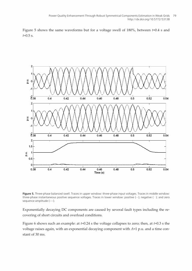
Figure 5 shows the same waveforms but for a voltage swell of 180%, between t=0.4 s andt=0.5 s.
Figure 5. Three-phase balanced swell. Traces in upper window: three-phase input voltages. Traces in middle window:three-phase instantaneous positive sequence voltages. Traces in lower window: positive (___); negative (…..); and zerosequence amplitude (----).
Exponentially decaying DC components are caused by several fault types including the re‐covering of short circuits and overload conditions.
Figure 6 shows such an example: at t=0.24 s the voltage collapses to zero; then, at t=0.3 s thevoltage raises again, with an exponential decaying component with A=1 p.u. and a time con‐stant of 30 ms.
Power Quality Enhancement Through Robust Symmetrical Components Estimation in Weak Gridshttp://dx.doi.org/10.5772/53138
79

Figure 6. Voltage collapse and recovering with a DC decaying component. Traces in upper window: three-phase inputvoltages. Traces in middle window: three-phase instantaneous positive sequence voltages. Traces in lower window:positive (___); negative (…..); and zero sequence amplitude (----).
Balanced voltage sags and swells have one and a half cycle time response. Decaying DCcomponents generate a not so small perturbation in the negative component but are effi‐ciently handled in the instantaneous positive sequence.
Different fault types can cause unbalanced voltage sags, possibly with phase steps. Frequen‐cy perturbations come from generation-consumption unbalance in static and dynamic con‐ditions. Frequency deviation steps are not usual in strong grids but can occur in weaksystems; continuous frequency deviations and phase steps are much more common. Threeconditions are presented in Figures 7, 8 and 9. In Figure 7, frequency goes from 50 Hz to 48Hz at t=0.3 s. With a time response of two cycles the frequency is correctly tracked with noamplitude errors.
An unbalanced voltage sag is presented in Figure 8, during the interval t=[0.2 s, 0.3 s]. In thiscase, phase a maintains its amplitude and phase while phase b decreases to an amplitude of0.577 with a phase jump of -30º and phase c decreases to the same amplitude of phase b witha phase jump of +30º. This condition generates a negative sequence component but not azero sequence one.
Power Quality Issues80

Another unbalanced condition, as referred in IEEE 1159 [25], is shown in Figure 9, duringthe time interval t=[0.4 s, 0.5 s]. While phase a maintains its amplitude and phase, phase bdecreases to an amplitude of 0.1 with a phase jump of -55º and phase c decreases to an am‐plitude of 0.5 with a phase jump of -20º, in a three-phase four-wire system. The three com‐ponents, positive, negative and zero, are now present in the three-phase system and areefficiently detected.
Frequency deviation and severe phase steps cause severe perturbations at different levels.As in symmetrical components estimation as in amplitude detection and frequency estima‐tion the perturbations are important but are correctly handled by the DFT-based estimationmethod.
Figure 7. Frequency change from 50 to 48 Hz. Upper window: real part of the positive sequence component. Middlewindow: errors in the estimation of the instantaneous positive three-phase components. Lower window: frequencyestimation.
Power Quality Enhancement Through Robust Symmetrical Components Estimation in Weak Gridshttp://dx.doi.org/10.5772/53138
81

Quite often there is the occurrence of harmonics in power systems: nonlinear loads generateharmonic currents and the associated voltage drops in the line impedances create voltageharmonics. These degrade the overall quality of the delivered power and can also severelyaffect the operation of grid-connected equipment. The DFT algorithm can easily extract theharmonics present in the three-phase voltages; in fact it is a common feature of any powerquality analyzer.
Figure 10 demonstrates the dynamic operation of the DFT algorithm in the estimation of thethree-phase instantaneous positive sequence and its magnitude in the following conditions:between t=0.1 s and t=0.2 s the voltage signal contains the following harmonics: 2nd with 1%,3rd with 5%, 5th with 10%, and 7th with 5%, and arbitrary phase; the frequency is maintainedin 50 Hz and the S/N ratio is 30 dB. As expected there is a very small disturbance in the esti‐mation of the symmetrical components magnitudes; the instantaneous positive sequence isalmost undisturbed.
Figure 8. Unbalanced voltage sag without zero sequence component. Upper window: three-phase input voltages.Second window: three-phase instantaneous positive sequence voltages. Third window: three-phase instantaneousnegative sequence voltages. Lower window: positive (___); negative (…..); and zero sequence amplitude (----).
Power Quality Issues82

Figure 9. Unbalanced voltage sag with zero sequence component. Upper window: three-phase input voltages. Sec‐ond window: three-phase instantaneous positive sequence voltages. Third window: three-phase instantaneous nega‐tive sequence voltages. Lower window: zero sequence component.
In low-voltage grids another important phenomenon already referred is the occurrence ofexponentially decaying DC components: if associated with low-frequency harmonics (e.g.caused by the switching of lightly filtered phase-controlled rectifiers) and noise they can se‐verely affect the operation of any analyzer or protection relay. In order to show this condi‐tion and the robustness property of the enhanced DFT algorithm Figure 11 is presented. Theused conditions are as follows: after t=0.098 s the voltage signal contains a decaying DCcomponent with a time constant of 30 ms and the following harmonics: 5th with 15%, and 7th
with 10%, and arbitrary phase; the frequency is 50 Hz and the S/N ratio is 20 dB. This is asevere condition; all the parameters related to power quality are affected: the positive andnegative sequences vary during almost two grid cycles; the estimated frequency suffers astrong transient. Comparing with Figure 10 it can be concluded that these perturbations aremainly caused by the DC component; low-frequency harmonics and a certain noise level arequite well tolerated by the DFT algorithm.
Power Quality Enhancement Through Robust Symmetrical Components Estimation in Weak Gridshttp://dx.doi.org/10.5772/53138
83

Figure 10. Positive sequence extraction under harmonics and noise. Upper window: three-phase input voltages. Mid‐dle windows: three-phase instantaneous positive sequence and its amplitude. Lower window: amplitude of the in‐stantaneous negative sequence (___) and zero sequence (---).
The DFT algorithm is immune to harmonics, but only at nominal frequency; when there is afrequency deviation from the nominal value the presented DFT-based method is also capa‐ble of maintaining harmonics immunity as is demonstrated in Figure 12. Between t=0.2 s andt=0.3 s, the frequency goes to 48 Hz and the signal contains the following harmonics: 2nd
with 5%, 3rd with 20%, 5th with 20%, and 7th, with 10%, and arbitrary phase.
Different noise types generated by electromagnetic interference, digital circuits or powerelectronics converters are always present in the acquired signals. Also, low frequency har‐monics due to nonlinear loads or saturated magnetic circuits are common in the grid volt‐age. Figure 13 shows the noise rejection capability of the presented DFT-based methodwhen the three-phase voltages contain the same harmonic level as in Figure 12 and are cor‐rupted by non-correlated random noise with a signal to noise ratio as low as 20 dB betweent=0.1 s and t=0.5 s, and 30 dB between t=0.6 s and t=1.0 s.
Power Quality Issues84

Figure 11. Exponentially decaying DC component, with harmonics and noise from t=0.098 s. Upper window: three-phase input voltages. Middle window: three-phase instantaneous positive sequence and its amplitude. Lower win‐dow: amplitude of the instantaneous negative sequence (---), zero sequence (….) and frequency deviation (___).
There is no noticeable perturbation in the amplitude detection or in the instantaneous posi‐tive sequence component estimation.
All the presented results are dependent on the imposed conditions; some can be managed inreal experimental implementations like noise level and low frequency harmonic distortion.The others are uncontrollable: sags, swells, AC fluctuation, DC decaying components, fre‐quency deviations and phase steps will occur in an unpredictable way and level. Any pha‐sor estimation method should be prepared to deal with them guaranteeing appropriatedynamics, stability, precision and robustness; the presented method does.
Power Quality Enhancement Through Robust Symmetrical Components Estimation in Weak Gridshttp://dx.doi.org/10.5772/53138
85

Figure 12. Harmonics immunity under frequency deviation. Upper window: three-phase input voltages. Middle win‐dow: three-phase instantaneous positive sequence voltages. Lower window: positive (___) and negative sequence am‐plitude (…..); and frequency deviation estimation (----).
5. Applications
As discussed in Section III.C and according to the diagram in Figure 1 and the flow diagramin Figure 2, the application of the DFT-based algorithm in the power quality domain can bedivided into two categories: real-time operation and off-line processing. Hard real-time isused in the synchronization of power electronics converters like STATCOMS or FACTS, inphasor estimation or control and in protection functions. Nearly real-time processing (or off-line) is used in quasi-steady-state conditions to evaluate power quality parameters like sym‐metrical components estimation, voltage sags, swells and harmonics, [1, 26-27].
The extraction of harmonics is made according to (21). Like the fundamental component, theh order harmonic can be estimated using the absolute or recursive version of (21).
Power Quality Issues86

21
0
2( ) ( )N ih
Nh
iX k x k i N e
N
p- -
== + -å (21)
The algorithm is based on intensive data processing and uses trigonometric functions andnonlinear functions to estimate the power quality parameters. A fundamental issue arisingin the case of harmonics detection is the number of samples needed (N); it must satisfy theNyquist criterion and highly increases the number of operations (and the required time)needed to estimate a range of harmonics. However, the use of fast A/D converters in con‐junction with FPGAs or DSPs allows an efficient solution to be used in spectrum and powerquality analyzers, [1].
Figure 13. Symmetrical components estimation precision with low frequency harmonics and noise presence. Fromt=0.1 s to t=0.5 s, S/N=20 dB; from t=0.6 s to t=1.0 s, S/N=30 dB. Upper window: three-phase input voltages. Middlewindow: amplitude of the instantaneous positive sequence. Lower window: amplitude of the instantaneous negativesequence (___) and zero sequence (----).
Power Quality Enhancement Through Robust Symmetrical Components Estimation in Weak Gridshttp://dx.doi.org/10.5772/53138
87

In case of variable frequency conditions (or frequency deviation) the power quality parame‐ters are estimated in quasi-steady-state. Instead of using a constant and fixed sampling fre‐quency a variable one is preferred and there are no errors due to a non-matched window.
As referred in [1], despite some issues (e.g. computational complexity, memory require‐ments, and data synchronization) it is predicted that new designs of PQ instruments will usethe FFT algorithm.
6. Conclusions
Power quality monitoring and power systems control and protection need fast and accuratefrequency and amplitude estimation. Also, instantaneous symmetrical components estima‐tion with amplitude and phase detection is needed for power systems stability analysis. Phe‐nomena like high amplitude voltage sags and swells, decaying DC components, phase andfrequency deviations, harmonics and noise are becoming more frequent and more intense,especially in weak grids. The corrupted voltage is difficult to manage in all conditions.
In this chapter, the recognized robustness of the DFT algorithm is extended to handle thisnew and more demanding grid voltage behaviour. The main errors caused by large frequen‐cy deviations and DC decaying components occurring in the DFT algorithm are acknowl‐edged and analyzed, and the associated corrections to deal with the referred parameters arepresented. The results, obtained in very unfavourable conditions, shown that it is needed acareful signal conditioning and a computationally powerful control platform in order to ob‐tain fast dynamics and high accuracy.
In terms of power quality monitoring, the enhanced DFT method is capable of detecting allrelated parameters: symmetrical components, voltage sags and swells, frequency deviationsand a range of harmonics. Its use is a requirement imposed by some Standards but its specif‐ic implementation in each PQ instrument or protection device has different possibilities. Thepresented DFT-based method has improved capabilities namely substantially improves therobustness to decaying DC components and frequency deviations.
Nomenclature
Δf frequency deviation
ϕ phase reference
τ time constant of exponential component
ω angular frequency
A magnitude of exponential component
a complex operator: a=exp(j2π/3)
b operator: b=exp(-1(foNτ))
Power Quality Issues88

e error
fo nominal frequency
fs sampling frequency
N number of samples per period
PS power sum
S120, S240 time delay operators
S/N signal to noise ratio
X magnitude of input signal
x(t) continuous input signal
x̄, x̄∗ phasor, complex conjugate of x̄
xc(k) corrected samples
va(t), vb(t), vc(t) phase-neutral voltage, phases a, b, c
vap(t), vb
p(t), vcp(t) positive sequence, phases a, b, c
van(t), vb
n(t), vcn(t) negative sequence, phases a, b, c
va0(t), vb
0(t), vc0(t) negative sequence, phases a, b, c
Acknowledgments
The Author wishes to thank José Miguel Ferreira for helpful discussions related to thiswork.
Author details
António Pina Martins
Address all correspondence to: [email protected]
Department of Electrical and Computer Engineering, Faculty of Engineering, University ofPorto, Rua Roberto Frias, s/n, Porto, Portugal
Power Quality Enhancement Through Robust Symmetrical Components Estimation in Weak Gridshttp://dx.doi.org/10.5772/53138
89

References
[1] Tarasiuk T. Comparative Study of Various Methods of DFT Calculation in the Wake ofIEC Standard 61000-4-7. IEEE Transactions on Instrumentation and Measurement, Oc‐tober 2009; 58(10) 3666-3677.
[2] Warichet J, Sezi T, Maun J-C. Considerations about Synchrophasors Measurement inDynamic System Conditions. Electrical Power and Energy Systems, 2009; 31, 452–464.
[3] International Electrotechnical Comission. IEC Standard 61000-4-30: Testing and Meas‐urement Techniques – Power Quality Measurement Methods. 2003.
[4] Phadke AG, Kasztenny B. Synchronized Phasor and Frequency Measurement underTransient Conditions. IEEE Transactions on Power Delivery, January 2009; 24(1) 89-96.
[5] McGrath BP, Holmes DG, Galloway J. Improved Power Converter Line Synchronisa‐tion using an Adaptive Discrete Fourier Transform (DFT). Proceedings of the IEEEPower Electronics Specialists Conference, Cairns, Queensland, Australia, June 2002,vol. 2, 821-826.
[6] Yang J-Z, Liu C-W. A Precise Calculation of Power System Frequency and Phasor. IEEETransactions on Power Delivery, April 2000; 15(2) 494-499.
[7] Yang J-Z, Liu C-W. A Precise Calculation of Power System Frequency. IEEE Transac‐tions on Power Delivery, July 2001; 16(3) 361-366.
[8] Jauch C, Sorensen P, Bak-Jensen B. International Review of Grid Connection Require‐ments for Wind Turbines. Proceedings of the Nordic Wind Power Conference, Chalm‐ers University of Technology, Sweden, March 2004.
[9] Hart D, Novosel D, Hu Y, Smith B, Egolf M. A New Frequency Tracking and PhasorEstimation Algorithm for Generator Protection. IEEE Transactions on Power Deliv‐ery, July 1997; 12(3) 1064-1073.
[10] Funaki T, Matsuura K, Tanaka S. Error Correction for Phase Detection by Recursive Al‐gorithm Real Time DFT. Electrical Engineering in Japan, 2002; 141(1) 8-17.
[11] Wang M, Sun Y. A Practical, Precise Method for Frequency Tracking and Phasor Esti‐mation. IEEE Transactions on Power Delivery, October 2004; 19(4) 1547-1552.
[12] Nakano K, Ota Y, Ukai H, Nakamura K, Fujita H. Frequency Detection Method basedon Recursive DFT algorithm. Proceedings of the 14th Power Systems Computation Con‐ference (PSCC), Sevilla, Spain, Session 1, Paper 5, June 2002.
[13] Benmouyal G. Removal of DC-offset in Current Waveforms Using Digital Mimic Fil‐tering. IEEE Transactions on Power Delivery, April 1995; 10(2) 621-630.
[14] Gu J-C. Yu S-L. Removal of DC Offset in Current and Voltage Signals Using a NovelFourier Filter Algorithm. IEEE Transactions on Power Delivery, January 2000; 15(1)73-79.
Power Quality Issues90

[15] Guo Y, Kezunovic M, Chen D. Simplified Algorithms for Removal of the Effect of Ex‐ponentially Decaying DC-Offset on the Fourier Algorithm. IEEE Transactions on Pow‐er Delivery, July 2003; 18(3) 711-717.
[16] Chen C-S, Liu C-W, Yang J-Z. A DC Offset Removal Scheme with a Variable Data Win‐dow for Digital Relaying. Proceedings of the Power Systems and Communications In‐frastructures for the Future Conference, Beijing, September 2002.
[17] Yang J-Z, Liu C-W. Complete Elimination of DC Offset in Current Signals for Relay‐ing Applications. Proceedings of the IEEE Power Engineering Society Winter Meet‐ing, vol. 3, pp. 1933-1038, Singapore, January 2000.
[18] Stevenson WD. Elements of Power System Analysis. New York: McGraw-Hill, 1995.
[19] Chen C-C, Zhu Y-Y. A Novel Approach to the Design of a Shunt Active Filter for anUnbalanced Three-Phase Four-Wire System under Nonsinusoidal Conditions. IEEETransactions on Power Delivery, October 2000; 15(4) 1258-1264.
[20] Hsu J-S. Instantaneous Phasor Method for Obtaining Instantaneous Balanced Funda‐mental Components for Power Quality Control and Continuous Diagnostics. IEEETransactions on Power Delivery, October 1998; 13(4) 1494-1500.
[21] Stankovic AM, Aydin T. Analysis of Asymmetrical Faults in Power Systems Using Dy‐namic Phasors. IEEE Transactions on Power Delivery, August 2000; 15(3) 1062-1068.
[22] Lobos T. Fast Estimation of Symmetrical Components in Real Time. IEE Proceedings-C, January 1992; 139(1) 27-30.
[23] Phadke AG, Thorp JS, Adamiak MG. A New Measurement Technique for TrackingVoltage Phasors, Local System Frequency, and Rate of Change of Frequency. IEEETransactions on Power Apparatus and Systems, May 1983; 102(5) 1025-1038.
[24] Andria G, Salvatore L. Inverter Drive Signal Processing via DFT and EKF. IEE Proceed‐ings, March 1990; 137, Pt. B, (2) 111-119.
[25] IEEE. IEEE Std 1159: Recommended Practice for Monitoring Electric Power Quality.2009.
[26] Caciotta M, Giarnetti S, Leccese F, Leonowicz Z. Comparison between DFT, Adap‐tive Window DFT and EDFT for Power Quality Frequency Spectrum Analysis. Pro‐ceedings of the Modern Electric Power Systems Conference 2010, September 20-22,2010, Wroclaw, Poland.
[27] Gallo D, Langella R, Testa A. Desynchronized Processing Technique for Harmonic andInterharmonic Analysis. IEEE Transactions on Power Delivery, July 2004; 19(3)993-1001.
Power Quality Enhancement Through Robust Symmetrical Components Estimation in Weak Gridshttp://dx.doi.org/10.5772/53138
91