
Power Plants and Basic Thermodynamic Cycles
15
Power Plant And Thermodynam ic cycles
-
Upload
salman-haider -
Category
Engineering
-
view
173 -
download
1
Transcript of Power Plants and Basic Thermodynamic Cycles
Power PlantAnd
Thermodynamic cycles
Syed Salman Haider NaqviMechanical EngineeringNED University of Engineering and Technology
P a g e | 1
Power Plants ____________________ Power plants or power stations are industrial facility that produces Electric Power. A powerstation is equipped with mechanical equipment running on Thermodynamic cycle converting Thermal Energy into Electrical Energy by the virtue of rotational motion of the prime mover.
The engines installed in a Power Station harvest energy from the fossil fuels which in exchange produces Electric Power
Fossil Fired Power StationA Fossil fired Power Station is a power station which burns fossil fuel such as coal, natural gas or petroleum to produce electricity. Fossil-fuel power stations have machinery to convert the heat energy of combustion into mechanical energy, which then operates an electrical generator. The prime mover may be a steam turbine, a gas turbine or, in small plants, a reciprocating internal combustion engine. All plants use the energy extracted from expanding gas, either steam or combustion gases.
Alternative Energy Harvesting StationsAlternatives to fossil fuel power plants include nuclear power, solar power, geothermal power, wind power, tidal power, hydroelectric power and other renewable energies. Some of these are proven technologies on an industrial scale.
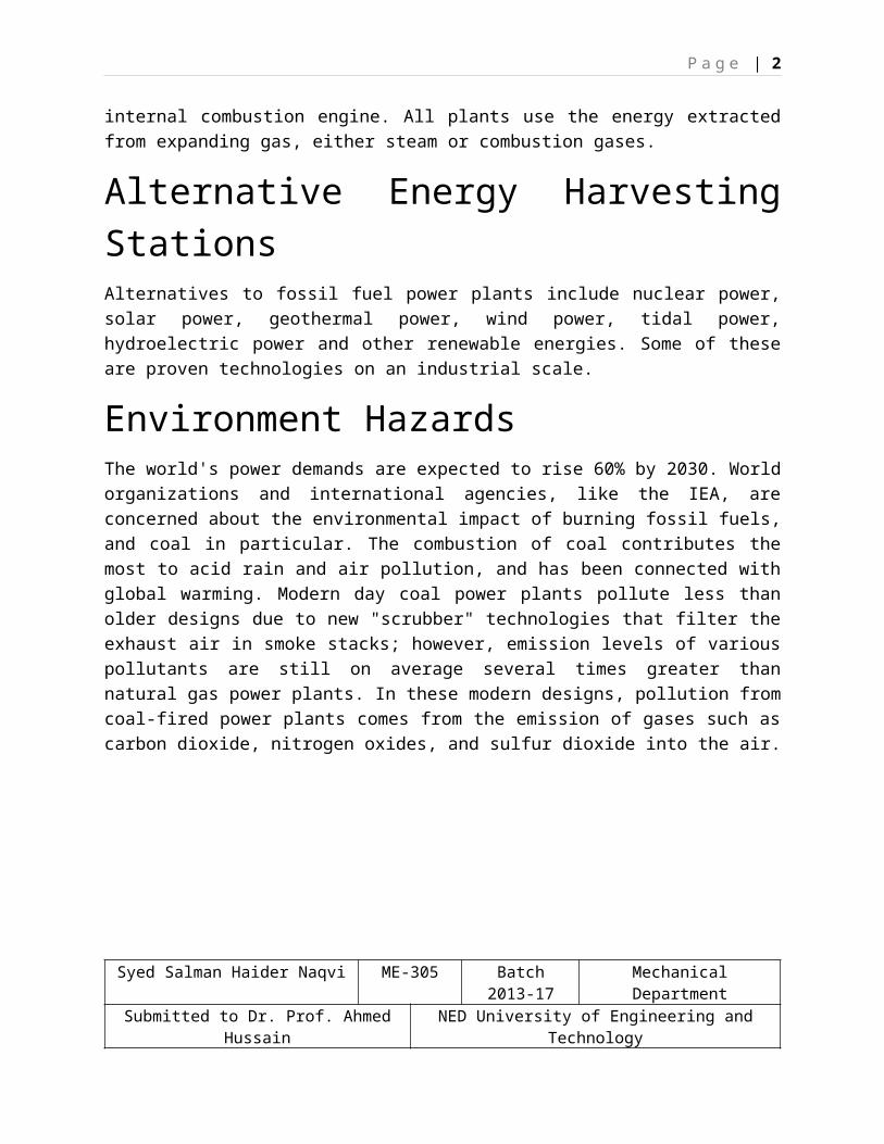
Environment HazardsThe world's power demands are expected to rise 60% by 2030. World organizations and international agencies, like the IEA, are concerned about the environmental impact of burning fossil fuels, and coal in particular. The combustion of coal contributes the most to acid rain and air pollution, and has been connected with global warming. Modern day coal power plants pollute less than older designs due to new "scrubber" technologies that filter the exhaust air in smoke stacks; however, emission levels of various pollutants are still on average several times greater than natural gas power plants. In these modern designs, pollution from coal-fired power plants comes from the emission of gases such as carbon dioxide, nitrogen oxides, and sulfur dioxide into the air.
Syed Salman Haider Naqvi ME-305 Batch 2013-17 Mechanical DepartmentSubmitted to Dr. Prof. Ahmed Hussain NED University of Engineering and Technology
P a g e | 2
Types of Power PlantsOn the basis of thermodynamic cycles or working mechanism, power plants can be categorized as followed
Thermal Power Plant Hydro-Electric Power Plant Nuclear Power Plant Renewable Energy Plants
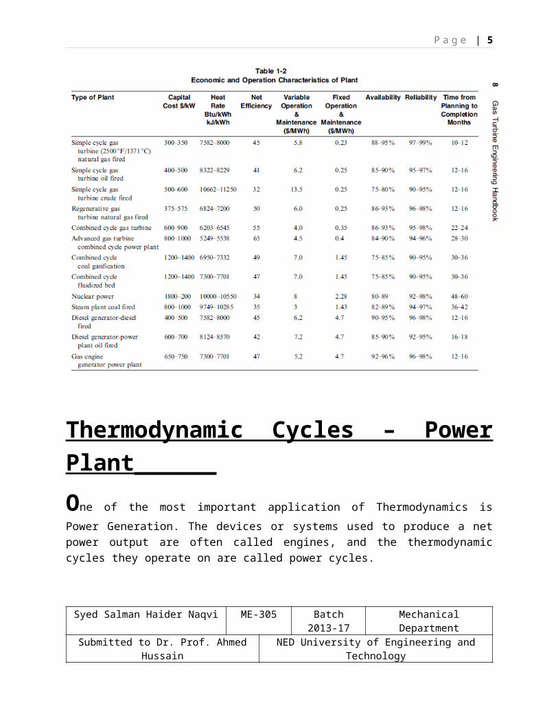
Commissioning of a Power Plant is a multi-Million Dollar Project. Furthermore, the venue of the plant and its type adds further into the budget. I.e. Solar Plant is a costly project compared to Simple Cycle Power Plant. But in long run Solar is found expensive and less energy is harvested. Whereas, Simple Cycle Plant can run 24/7 provided supply of fuel is not compromised.
Following chart displays facts and figures of different types of Power Station.
Syed Salman Haider Naqvi ME-305 Batch 2013-17 Mechanical DepartmentSubmitted to Dr. Prof. Ahmed Hussain NED University of Engineering and Technology
P a g e | 3
Thermodynamic Cycles – Power Plant______One of the most important application of Thermodynamics is Power Generation. The devices or systems used to produce a net power output are often called engines, and the thermodynamic cycles they operate on are called power cycles.
Syed Salman Haider Naqvi ME-305 Batch 2013-17 Mechanical DepartmentSubmitted to Dr. Prof. Ahmed Hussain NED University of Engineering and Technology

P a g e | 4
Gas cycles, the working fluid remains in the gaseous phase throughout the entire cycle. Vapor cycles the working fluid exists in the vapor phase during one part of the cycle and
in the liquid phase during another part.
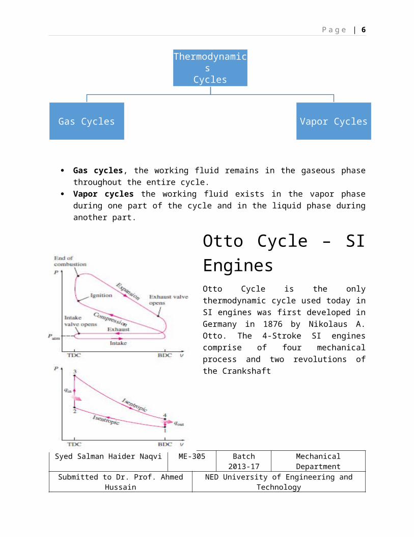
Otto Cycle – SI EnginesOtto Cycle is the only thermodynamic cycle used today in SI engines was first developed in Germany in 1876 by Nikolaus A. Otto. The 4-Stroke SI engines comprise of four mechanical process and two revolutions of the Crankshaft
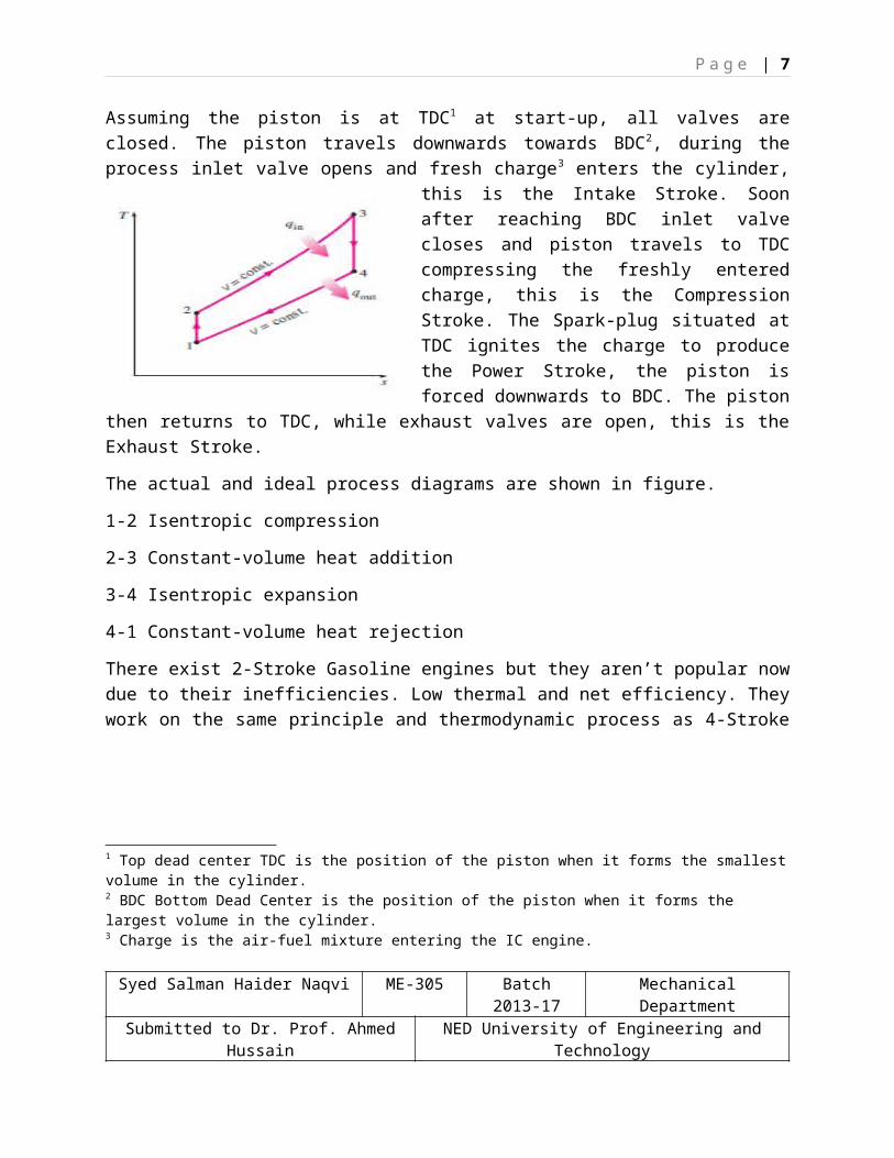
Assuming the piston is at TDC1 at start-up, all valves are closed. The piston travels downwards towards BDC2, during the process inlet valve opens and fresh charge3 enters the cylinder, this is the Intake Stroke. Soon after reaching BDC inlet valve closes and piston travels to TDC compressing the freshly entered charge, this is the Compression Stroke. The Spark-plug situated at TDC ignites the charge to produce the Power Stroke, the piston is forced downwards to BDC. The piston then returns to TDC, while exhaust valves are open, this is the Exhaust Stroke.
1 Top dead center TDC is the position of the piston when it forms the smallest volume in the cylinder.2 BDC Bottom Dead Center is the position of the piston when it forms the largest volume in the cylinder.3 Charge is the air-fuel mixture entering the IC engine.
Syed Salman Haider Naqvi ME-305 Batch 2013-17 Mechanical DepartmentSubmitted to Dr. Prof. Ahmed Hussain NED University of Engineering and Technology
Thermodynamics Cycles
Gas Cycles Vapor Cycles
P a g e | 5
The actual and ideal process diagrams are shown in figure.
1-2 Isentropic compression
2-3 Constant-volume heat addition
3-4 Isentropic expansion
4-1 Constant-volume heat rejection
There exist 2-Stroke Gasoline engines but they aren’t popular now due to their inefficiencies. Low thermal and net efficiency. They work on the same principle and thermodynamic process as 4-Stroke engines. The MEP4 and Compression Ratio5 “r” for a Gasoline engine are also a major factor to consider. In SI engines compression ratio ranges from 6-10 before Auto-Ignition and knocking.
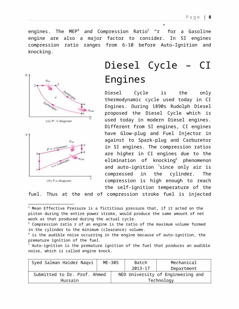
Diesel Cycle – CI EnginesDiesel Cycle is the only thermodynamic cycle used today in CI Engines. During 1890s Rudolph Diesel proposed the Diesel Cycle which is used today in modern Diesel engines. Different from SI engines, CI engines have Glow-plug and Fuel Injector in against to Spark-plug and Carburetor in SI engines. The compression ratios are higher in CI engines due to the elimination of knocking6 phenomenon and auto-ignition 7since only air is compressed in the cylinder. The compression is high enough to reach the self-ignition temperature of the fuel. Thus at the end of compression stroke fuel is injected through the nozzle into the compressed air stream having temperatures higher then self-ignition temperature of the fuel (self-ignition temperature of Diesel is 256oC). The compression ratios in CI engines ranges from 12-24. The function of the glow-plug is to preheat the air in the cylinder at start-up only.
4 Mean Effective Pressure is a fictitious pressure that, if it acted on the piston during the entire power stroke, would produce the same amount of net work as that produced during the actual cycle.5 Compression ratio r of an engine is the ratio of the maximum volume formed in the cylinder to the minimum (clearance) volume.6 is the audible noise occurring in the engine because of auto-ignition, the premature ignition of the fuel.7 Auto-ignition is the premature ignition of the fuel that produces an audible noise, which is called engine knock.
Syed Salman Haider Naqvi ME-305 Batch 2013-17 Mechanical DepartmentSubmitted to Dr. Prof. Ahmed Hussain NED University of Engineering and Technology
P a g e | 6
The Thermodynamic process as shown in fig(a) is elaborated as followed.
1-2 Isentropic Compression
2-3 Constant Pressure Heat Addition
3-4 Isentropic Expansion
4-1 Constant Volume Heat Rejection
The higher efficiency and lower fuel costs of diesel engines make them attractive in applications requiring relatively large amounts of power, such as in locomotive engines, emergency power generation units, large ships, and heavy trucks.
The EDG (emergency diesel generator) used in BQPS II – K-Electric is a 1.8MW V-16 CI Engine.
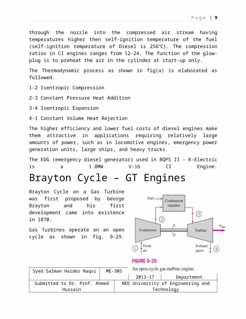
Brayton Cycle – GT EnginesBrayton Cycle on a Gas Turbine was first proposed by George Brayton and his first development came into existence in 1870.
Gas Turbines operate on an open cycle as shown in fig. 9-29. Fresh Air at ambient8
conditions is sucked into the compressor where it’s temperature and pressure are raised. The compression ratio ranges from 15-40 in modern GTs. The compressed air then travels to the combustion chamber where the burners are present and fuel is injected and burned at constant pressure. The high temperature and pressure gases then expands in the turbine section where it’s pressure is reduced back to ambient or atmospheric pressure.
The Thermodynamic Brayton cycle as closed cycle is as followed.
8 Ambient conditions are the live atmospheric temperature and pressure readings.
Syed Salman Haider Naqvi ME-305 Batch 2013-17 Mechanical DepartmentSubmitted to Dr. Prof. Ahmed Hussain NED University of Engineering and Technology
P a g e | 7
1-2 Isentropic compression 9(in a compressor)
2-3 Constant-pressure heat addition
3-4 Isentropic expansion (in a turbine)
4-1 Constant-pressure heat rejection
The T-s and P-v diagrams of an ideal Brayton cycle are shown in Fig. 9–31.
The two major application areas of gas-turbine engines are aircraft propulsion and electric power generation. When it is used for aircraft propulsion, the gas turbine produces just enough power to drive the compressor and a small generator to power the auxiliary equipment. The high-velocity exhaust gases are responsible for producing the necessary thrust to propel the aircraft. Gas turbines are also used as stationary power plants to generate electricity as stand-alone units or in conjunction with steam power plants on the high-temperature side. In these plants, the exhaust gases of the gas turbine serve as the heat source for the steam.
There are 3 GTs General Electric PG9171E - 129.1 MW installed in BQPS II K-Electric.
Rankine Cycle – ST Engine
Rankine Cycle is a type of Vapor cycle, based on closed cycle configuration. An Ideal Rankine Cycle involves the following thermodynamic processes.
1-2 Isentropic compression in a pump9 Isentropic process is an internally reversible and adiabatic process. In such a process the entropy remains constant.
Syed Salman Haider Naqvi ME-305 Batch 2013-17 Mechanical DepartmentSubmitted to Dr. Prof. Ahmed Hussain NED University of Engineering and Technology
P a g e | 8
2-3 Constant pressure heat addition in a boiler
3-4 Isentropic expansion in a turbine
4-1 Constant pressure heat rejection in a condenser
The saturated water in entered into the pump at state 1 where its compressed and pressure is increased to boiler operating pressure. The temperature is also raised in the isentropic compression process from state 1 to state 2. The saturated compressed water is then entered in the boiler region where it exits as a high temperature and pressure Super-Heated Vapor at state 3. The energy required for phase transformation is provided through a nuclear reactor, Coal or Natural Gas burner or through the exhaust of GT in HRSG. The super-heated vapor at about 90-100bar pressure then enters into the turbine section where it drives the Steam Turbine, from state 3 to state 4. The low pressure wet steam at the exit of the turbine is then drawn into the condenser, where pressure is maintained below atmospheric pressure. The condenser acts as a heat sink where all the heat of wet steam is extracted and saturated water is re-produced from state 4 to state 1. The ST’s used in conjunction with GTs have a net efficiency of 45%, installed in BQPS II K-Electric.
Combined Cycle Power Plants
The conquest to produce more power brings us to mechanical limit, where more energy was at expense of material design and metallurgy. Here Combined Cycle was introduced, boosting the relative efficiency to 45% and in some cases 60% for Advanced Combined Cycle Power Plants.
A combined cycle is a junction of Gas cycle and Vapor Cycle. Brayton and Rankine cycle and junction together to give higher work output.
Syed Salman Haider Naqvi ME-305 Batch 2013-17 Mechanical DepartmentSubmitted to Dr. Prof. Ahmed Hussain NED University of Engineering and Technology
P a g e | 9
The Exhaust of a GT is a very high temperature gas. The temperature of exhaust ranges from 500-700oC+. Since over time the metallurgy of the material used in GT has improved and is more temperature resistant was ceramic coating and can bear upto 1500 oC+ temperature, resulting in higher exhaust temperature. The exhaust gases then are sent to heat exchangers HRSG (heat regenerative steam generation), here the heat of exhaust is exchanged with the
boiler water. This results in high super-heated vapor formation for running a ST. The pressure of super-heated vapor is maintained at 90-100bar before sending it to the ST.
The efficiencies of a CCPP is 45% at average. The evolution of mechanical design and calibration has resulted into a more productive and lower cost energy production.
The two cycles in the combined cycle system are independent, with the syncing medium is a heat exchanger HRSG.
A 560MW CCPP Bin Qasim Power Station II K-Electric was commissioned in 2012 and is fully operational.
References
1. Gas Turbine Engineering Handbook – Meherwan P. Boyce 2nd Edition2. Thermodynamics an Engineering Approach – Yunus A. Cengel3. Internal Combustion Engines – G.W. Ganeson4. https://en.wikipedia.org/wiki/Power_station5. https://en.wikipedia.org/wiki/Fossil-fuel_power_station
Syed Salman Haider Naqvi ME-305 Batch 2013-17 Mechanical DepartmentSubmitted to Dr. Prof. Ahmed Hussain NED University of Engineering and Technology