Power over Ethernet Application for IP Network Camera (IPNC)
27
TI Information – Selective Disclosure TI Information – Selective Disclosure Gary Chen Field Application Engineer Texas Instruments 11-13-19 1 Power over Ethernet Application for IP Network Camera (IPNC)
Transcript of Power over Ethernet Application for IP Network Camera (IPNC)

TI Information – Selective Disclosure TI Information – Selective Disclosure
Gary Chen
Field Application Engineer
Texas Instruments
11-13-19
1
Power over Ethernet Application for IP Network Camera (IPNC)

TI Information – Selective Disclosure
Agenda
• IP Network Camera (IPNC) Block Diagram Overview
– PoE Power Schematic
• Power over Ethernet (PoE) Introduction
– What is PoE?
– Value of PoE
– End Equipment using PoE
• PoE Basics
– Alternative A, Alternative B and 4 Pair PoE
– Types & Classes
– PSE and PD Handshake: Detection, Classification, Power on and Normal Operation.
• Ethernet Alliance (EA)
• PoE Design Block for IPNC
2

TI Information – Selective Disclosure
Non-Isolated AC/DC Power
Supply
Energy
Storage
Output User
Interface
Input Power
Protection
Power over Ethernet
Audio Interface
Signal Input/
Output Protection
Environmental
Sensing
IP Network Camera (IPNC) Block Diagram Overview
Self-Diagnostics/
Monitoring
Digital Media
Processor
Wireless Interface
Wired Interface
Ethernet
Wi-Fi Radio
Sub 1-GHz or
2.4-GHz Radio
TPS2595x
Real Time
Clock
Temp.
Monitor
Voltage
Supervisor
MPU
Status LEDs Memory
DDR Memory
Flash
DDR
Termination
Voltage
Translators
12V / 24V DC
or Battery
12V / 24V AC
OR’ing
Controller
Backup
Battery
Battery Gas
Gauge
Non-Isolated DC/DC Power Supply
LDO VCC2
DC/DC VCC1
PMIC MPU FETs
Temp/ Hum.
Sensor
Light
Sensor
AFE Thermistor
MPU
MPU
Motion Detection
AFE PIR Sensor
ULN2003
RS-485 /
RS-232 TPS2595x
PoE I/F &
Converter Transformer
Voltage Ref.
Audio CODEC
Microphone ESD
Amp
Amp ADC
DAC Speaker Audio
Switch
USB TPS2595x
Motor Driver
Motor Driver Auto-Iris
Control
CCD/CMOS Sensor
IR LED Illumination
IR LED LED
Driver
Parallel/CSI2
AFE MPU
MPU
TPS2660/2x /
TPS2595x
TPS2660x /
TPS2595x
Power Interface
MOSFETs
Power
Sequencer
Tamper Detection
Hall Effect
Sensor
Inductive
Sensor
Capacitive
Sensor
TPS2660/2 /
TPS2595x
TPS22913/
TPS22916
TPS22913/
TPS22916
POL
3
1
2 DRV8830
TPS54200
TLV62569
TLV743P
TPA2011
LP3943
DRV5023
TXS0104
TPS23756
BQ25895
BQ27220
OPT3004
HDC2010
TMP103
DP83822
TRS3122E
THVD1429
TUSB422

TI Information – Selective Disclosure
PoE Power Schematic
4
PD + PWM
PoE Input Adapter Input
VDD
VDD
VDD
System
POL
Power over Ethernet
PoE I/F &
Converter Transformer
POL
DC/DC PWM PD Handshake

TI Information – Selective Disclosure
Agenda
• IP Network Camera (IPNC) Block Diagram Overview
– PoE Power Schematic
• Power over Ethernet (PoE) Introduction
– What is PoE?
– Value of PoE
– End Equipment using PoE
• PoE Basics
– Alternative A, Alternative B and 4 Pair PoE
– Types & Classes
– PSE and PD Handshake: Detection, Classification, Power on and Normal Operation.
• Ethernet Alliance (EA)
• PoE Design Block for IPNC
5

TI Information – Selective Disclosure
What is PoE? • Definition: Providing DC power (44V to 57V) over same CAT5 twisted-pair cable that carries Ethernet data.
• Ends of the cable
– Power Sourcing Equipment (PSE): Ethernet Switch, Router, Hub
– Powered Device (PD): IP Phone, Wireless Access Point, Security Camera
6
Ethernet Switch
Ethernet
Device
Ethernet
Device
PSE PD
Data
Power

TI Information – Selective Disclosure 7
1. Convenience of installation & use
– Power & data cables combined
– The length of CAT5 cable can be up to 100m
– Ease of installation (no electricians required for install)
2. Reliability and longevity
– IEEE 802.3 standard based
– PoE end equipments have long lifetimes and part obsolescence is uncommon
3. Adjustable power levels to meet various demands
– Scalability up to 71W at the load!
4. Power Redundancy
– Data and power
– Battery packs, AC/DC power, etc.
5. Plug into any RJ-45 port without concern for damaging equipment
– For IEEE802.3 compliant devices, the PSE will not supply power to non-compliant PD devices or data only ports.
Value of PoE
Ethernet Switch
Laptop

TI Information – Selective Disclosure
• PD • PSE
Primary Applications using PoE PoE helps to reduce power cabling where CAT5 is already needed for Data
Enterprise Switch IP Camera
IP Phone
Wireless Access Point Small Cells
PoE Injector
PoE Pass Through
8
TI Information – Selective Disclosure
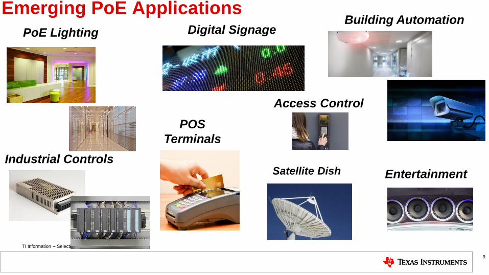
Emerging PoE Applications
Access Control
POS
Terminals
Entertainment
Industrial Controls
PoE Lighting Digital Signage Building Automation
Satellite Dish
9

TI Information – Selective Disclosure
Agenda • IP Network Camera (IPNC) Block Diagram Overview
– PoE Power Schematic
• Power over Ethernet (PoE) Introduction
– What is PoE?
– Value of PoE
– End Equipment using PoE
• PoE Basics
– Alternative A, Alternative B and 4 Pair PoE
– Types & Classes
– PSE and PD Handshake: Detection, Classification, Power on and Normal
Operation.
• Ethernet Alliance (EA)
• PoE Design Block for IPNC 10

TI Information – Selective Disclosure
PoE Basics | How Much Power can I send?
PoE evolution driven by desire for more Power!
2019
2009
2003
IEEE 802.3 af PSE=15.4W
PD=13W
Type 1
IEEE 802.3 at PSE=30W
PD=25.5W
Type 2
IEEE 802.3 bt PSE=90W
PD=71W
Type 3-4
11
100m of cable

TI Information – Selective Disclosure
IEEE802.3at 2-Pair Wiring
12
1. There are 4 pairs in an Ethernet cable
– Each pair consists of 2 twisted wires.
2. We use 2 pairs to deliver power in AT standard.
There are 2 options for wiring:
– Alternative A: Wires 1&2 + Wires 3&6
– Alternative B: Wires 4&5 + Wires 7&8
3. Power is injected by the PSE on the isolated side
of the transformer
4. The PD receives power on the isolated side of the
transformer
TI Information – Selective Disclosure
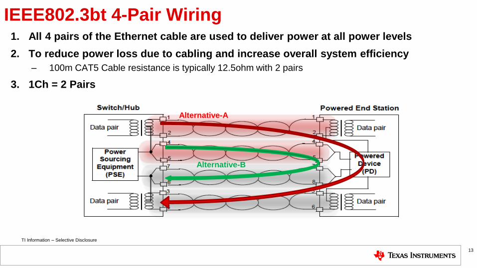
IEEE802.3bt 4-Pair Wiring 1. All 4 pairs of the Ethernet cable are used to deliver power at all power levels
2. To reduce power loss due to cabling and increase overall system efficiency
– 100m CAT5 Cable resistance is typically 12.5ohm with 2 pairs
3. 1Ch = 2 Pairs
13
Alternative-A
Alternative-B

TI Information – Selective Disclosure
PoE Basics | IEEE802.3af (2003) Types & Classes
Class Type # Pairs Power Sourced
at PSE
Power at PD
after 100m of
cat5e cable
0 1 2 15.4W 13.0W
1 1 2 4W 3.84W
2 1 2 7W 6.49W
3 1 2 15.4W 13.0W
14

TI Information – Selective Disclosure
PoE Basics | IEEE802.3at (2009) Types & Classes
Class Type # Pairs Power Sourced
at PSE
Power at PD
after 100m of
cat5e cable
0 1 2 15.4W 13.0W
1 1 2 4W 3.84W
2 1 2 7W 6.49W
3 1 2 15.4W 13.0W
4 2 2 30W 25.5W
15

TI Information – Selective Disclosure
PoE Basics | IEEE802.3bt (2019) Types &Classes
Class Type # Pairs Power Sourced
at PSE
Power at PD
after 100m of
cat5e cable
0 1 2 15.4W 13.0W
1 1 or 3 2 or 4 4W 3.84W
2 1 or 3 2 or 4 7W 6.49W
3 1 or 3 2 or 4 15.4W 13.0W
4 2 or 3 2 or 4 30W 25.5W
5 3 4 45W 40.0W
6 3 4 60W 51.0W
7 4 4 75W 62.0W
8 4 4 90W 71.3W
The new IEEE802.3bt standard add Types 3 and 4 & Classes 5-8 to accommodate
sourced power levels up to 90W
16

TI Information – Selective Disclosure
PoE Basics | Detection
• The IEEE802.3 standards define a method of safely powering a PD (powered device) over a cable, and
then removing power if a PD is disconnected.
• The PSE leaves the cable unpowered while it periodically looks to see if something has been plugged in. This is called
Detection.
• How does Detection work?
– PSE sends 2 low voltage signals to PD (2.7V–10.1V) 2-point Detection
– Measures dV/dI across Rdet
– Acceptable detection if 23.75kΩ< Rdet <26.25kΩ
– 4-point Detection 2-point Detection twice
17
PSE Detection Signal
PD Detection
Resistor 2.7V
10.1V
Ap
plie
d P
SE
Vo
lta
ge

TI Information – Selective Disclosure
2 Classification
Resistors on PD
PoE Basics | Classification • If a valid PD signature is present, the PSE may inquire how much power the PD requires. This is referred to as
Classification.
• How does classification work?
1. PSE sends voltage signals to PD (14.5V - 20.5V)
2. PD removes Rdet and turns on internal LDO which applies 2.5V
across the Rclass
3. PSE Measures current through Rclass
4. Classification determines power allotment from PSE
18
PSE Classification Signal
14.5V
20.5V
Ap
plie
d P
SE
Vo
lta
ge
1 Classification Resistor
on PD AF&AT
BT

TI Information – Selective Disclosure
PD & PSE Handshake | AF&AT Standard
19
• AT Standard
Detection
DEN CLS
T2P
Low: Can support Type2 Power
High: Only support Type1 Power
Detection Classification
PSE
PD
Hardware Classification
To let load know if PSE is
Type1 or Type2 power level

TI Information – Selective Disclosure
PD & PSE Handshake | BT. Standard
20
• BT Standard • PSE sends longer 1st finger to inform PD that it’s Type3 or Type4 PSE.
• PD uses 2nd Rclass to identify higher power level.
• PSE sends total 5 fingers for maximum 90W power
DEN
CLSA
X CLSB
X
TPH
TPL
BT
Detection Classification
PSE
PD
Hardware Classification
BT: Type1-2 or Type3-4 PSE
TPH/TPL: Presents the numbers of fingers

TI Information – Selective Disclosure
PoE Basics | Inrush and Normal Operation
• After a valid classification result (not overcurrent or class mismatch), PSE will turn on the port and start monitoring inrush
current.
– At this time, 48V typically (could be in the range of 44V to 57V) is sent from the PSE to the PD across the Ethernet
cable.
• Inrush Current Limiting
– Once 48V is applied by PSE to PD, PSE will turn on the port and start monitoring inrush current. At the same time,
PD takes the control to limit the inrush current. If the current keeps below PSE’s inrush current limit during Tstart
(maximum allowed overcurrent time during inrush) period, PD will pull full load and the port starts normal operating.
• Normal Operation
– During normal operation, the PSE checks to see if amount of power sent down the cable is within the allocated
power class and current limits if needed to prevent the PD from drawing more power than was allocated.
– PSE must also continually detect Maintain Power Signature (MPS) from PD to stay connected during light load
operation.
21

TI Information – Selective Disclosure
Agenda
• IP Network Camera (IPNC) Block Diagram Overview
– PoE Power Schematic
• Power over Ethernet (PoE) Introduction
– What is PoE?
– Value of PoE
– End Equipment using PoE
• PoE Basics
– Alternative A, Alternative B and 4 Pair PoE
– Types & Classes
– PSE and PD Handshake: Detection, Classification, Power on and Normal Operation.
• Ethernet Alliance (EA)
• PoE Design Block for IPNC
22

TI Information – Selective Disclosure
What does the Logo Mean?
• Meets Ethernet Alliance Certification Test Plan
– Based on IEEE Std 802.3™-2015 PoE Specifications
• Confidence of interoperability between certified
products
• PSE / PD Logo Distinction
• Class Number indicates maximum class supported
• Easy Interoperability: PSE Class must be greater than
or equal to PD Class
• Initial rollout (called ‘GEN1’) limited to Class 4 and
lower; ‘GEN2’ is in definition and will go up to Class 8
• Read more here in our Blog
PSE Class “4” Logo
PD Class “1” Logo
23

TI Information – Selective Disclosure
Agenda
• IP Network Camera (IPNC) Block Diagram Overview
– PoE Power Schematic
• Power over Ethernet (PoE) Introduction
– What is PoE?
– Value of PoE
– End Equipment using PoE
• PoE Basics
– Alternative A, Alternative B and 4 Pair PoE
– Types & Classes
– PSE and PD Handshake: Detection, Classification, Power on and Normal Operation.
• Ethernet Alliance (EA)
• PoE Design Block for IPNC
24
TI Information – Selective Disclosure
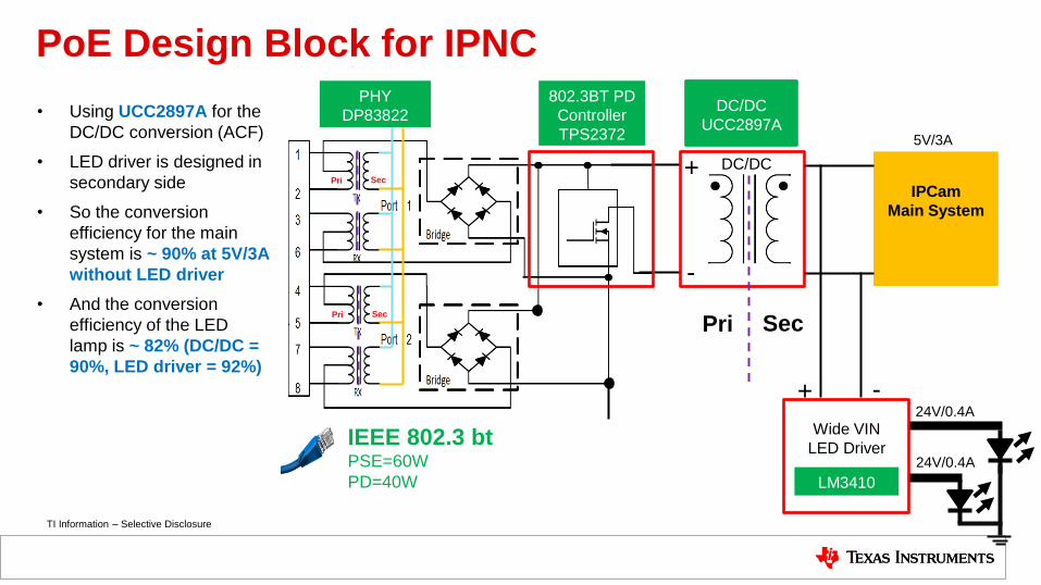
PoE Design Block for IPNC
LM3410
DC/DC
UCC2897A
IEEE 802.3 bt PSE=60W
PD=40W
+
-
Wide VIN
LED Driver
IPCam
Main System
DC/DC
802.3BT PD
Controller
TPS2372
- +
Pri Sec
PHY
DP83822
Pri
Pri Sec
Sec
5V/3A
24V/0.4A
24V/0.4A
• Using UCC2897A for the
DC/DC conversion (ACF)
• LED driver is designed in
secondary side
• So the conversion
efficiency for the main
system is ~ 90% at 5V/3A
without LED driver
• And the conversion
efficiency of the LED
lamp is ~ 82% (DC/DC =
90%, LED driver = 92%)

TI Information – Selective Disclosure
How to get familiar with TI portfolio (TI.com/PoE)
26

TI Information – Selective Disclosure
Thank you
27