POWER OUTLETS OR FIXED WIRING MUST BE INSTALLED...
24
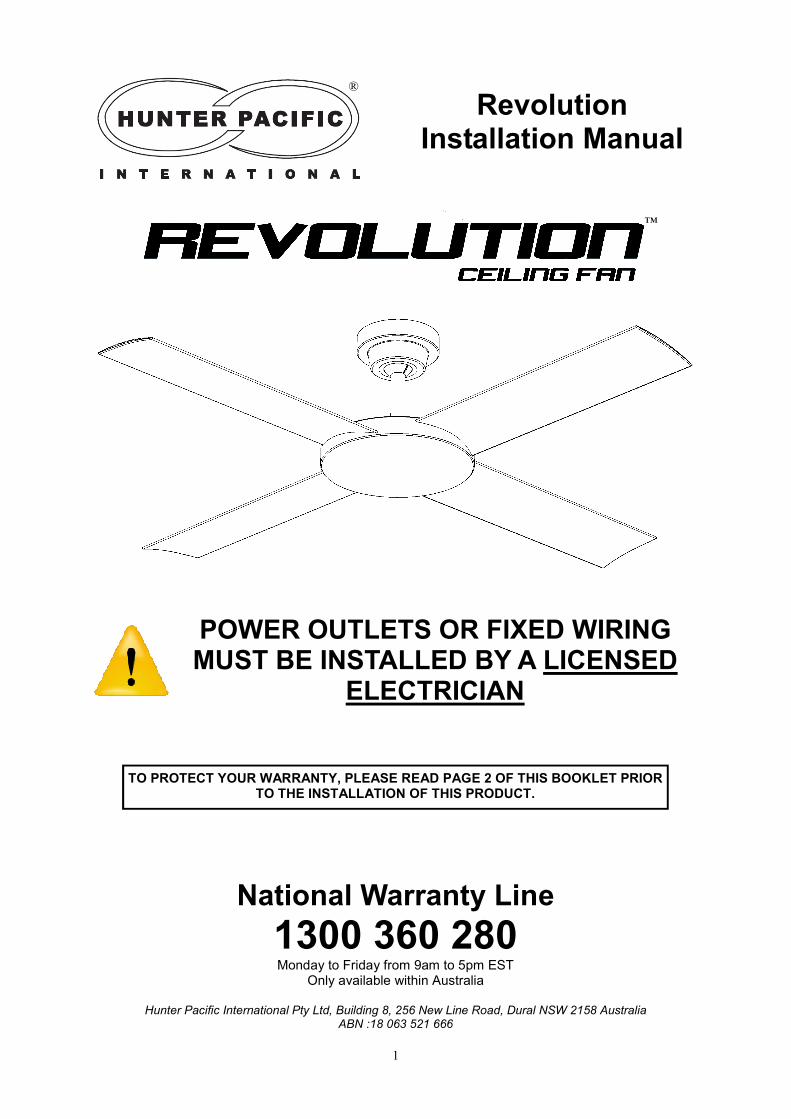
1 Revolution Installation Manual POWER OUTLETS OR FIXED WIRING MUST BE INSTALLED BY A LICENSED ELECTRICIAN National Warranty Line 1300 360 280 Monday to Friday from 9am to 5pm EST Only available within Australia Hunter Pacific International Pty Ltd, Building 8, 256 New Line Road, Dural NSW 2158 Australia ABN :18 063 521 666 TO PROTECT YOUR WARRANTY, PLEASE READ PAGE 2 OF THIS BOOKLET PRIOR TO THE INSTALLATION OF THIS PRODUCT. ™ ®
Transcript of POWER OUTLETS OR FIXED WIRING MUST BE INSTALLED...
1
Revolution Installation Manual
POWER OUTLETS OR FIXED WIRING MUST BE INSTALLED BY A LICENSED
ELECTRICIAN
National Warranty Line
1300 360 280 Monday to Friday from 9am to 5pm EST
Only available within Australia
Hunter Pacific International Pty Ltd, Building 8, 256 New Line Road, Dural NSW 2158 Australia ABN :18 063 521 666
TO PROTECT YOUR WARRANTY, PLEASE READ PAGE 2 OF THIS BOOKLET PRIOR TO THE INSTALLATION OF THIS PRODUCT.
™
®
2
IMPORTANT INFORMATION READ PRIOR TO INSTALLATION
1. Installer details and purchase receipts are essential for warranty claims and must be available upon demand. A page towards the back of this manual has been allocated to allow you to record these details.
2. Power outlets, switches and fixed wiring products must only be installed by persons who are ap-
propriately licensed by the applicable State regulatory body. Therefore, to protect our repair per-sonnel, on-site warranty claims will not be accepted if power outlets or fixed wiring has been per-formed by unlicensed persons.
3. Damage caused by incorrect installation, force-majeure, electrical surges, lightning, power grid
fluctuations, water or by connection to stand alone alternative power supply sources (such as non-grid solar inverters, etc.) is not eligible for warranty repair.
4. When products are installed in a location requiring special access equipment (such as scaffolding or scissor lifts, etc) the cost of providing, installing and operating special access
equipment must be borne by the site owner.
For safety, and to protect your warranty, the following must be taken into account when installing and operating the product(s):
ATTENTION ELECTRICIANS:
This product must be installed using an ON/OFF wall switch to aid in Control Module programming and troubleshooting. If it is not possible to use a wall switch then the Control Module and Handsets must be checked before installation. To do so connect the Control Module to a standard GPO and verify the Control Module beeps when buttons are pressed on the hand piece. If not program the unit as per page 17.
IF THERE ARE ANY PROBLEMS WITH THE PRODUCT AT TIME OF INSTALLATION THE INSTALLER MUST CONTACT THE WARRANTY
HOT LINE NUMBER 1300 360 280. BEFORE LEAVING THE JOB
SITE. PLEASE DO NOT REMOVE THE FAN FROM THE CEILING ONCE INSTALLED UNLESS INSTRUCTED TO DO SO.
(a) DO NOT USE WALL CONTROLLERS. Other than a simple On/Off switch (b) The power outlet must provide an earth. (c) Mounting bracket must be firmly screwed to a solid structure such as a concrete ceiling,
steel structure or timber framing. If additional bracing is added it must be firmly secured to the rafters and not left floating on the ceiling. Special mounts, such as T-hooks, are
available for certain types of installation. (d) After installation, fan blades must be at least 2.1 m (7 feet) above floor level. (e) The use of these products by children and the infirm must be under supervision.
Revolution Installation Manual
®
3
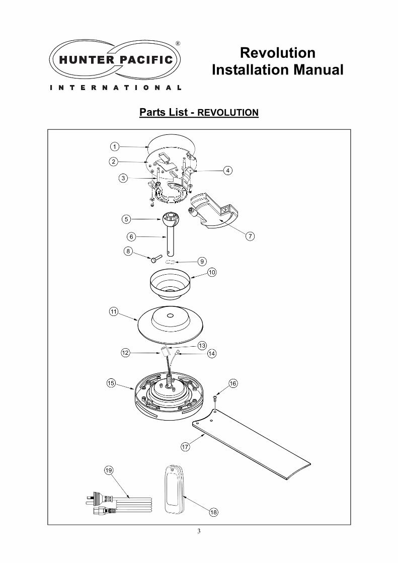
Parts List - REVOLUTION
Revolution Installation Manual
®

4
1. Do not attempt to operate the fan with any wall control. This fan operates using remote control or optional special modules only. Contact Hunter Pacific International for details. Any modification or attempt to directly wire the fan will void warranty unless those modifications are authorised.
Revolution Installation Manual
®
IMPORTANT INFORMATION The table below contains information that can help you quickly identify the product you are installing. If you have any difficulties installing our product, we recommend you to call our warranty line on 1300 360 280 for advice.
REVOLUTION Ceiling Fans 132cm (52”)
CODE FAN MODEL NAME COLOUR
A0180 REVOLUTION White Motor & Blades
A0181 REVOLUTION Matt Black Motor & Blades
A0182 REVOLUTION Brushed Aluminium Motor & Brushed Silver Blades
A0183 REVOLUTION Pearl Ice Motor & Blades
A0184 REVOLUTION Black Ice Motor
& Black Ice UV coated Blades
A0185 REVOLUTION Silver Ice Motor
& Silver Ice UV coated Blades
REVOLUTION Ceiling Fan Parts List
No. Part Quantity No. Part Quantity
1 Silicone pad 1 11 Motor Canopy 1
2 Plate 1 12 Motor Plug 1
3 Hex Head Screw 2 13 Motor Plug Clip 1
4 Hanger Bracket 1 14 Tether 1
5 Ball Joint 1 15 Motor Housing 1
6 Down Rod (26mm Diameter) 1 16 Blade Screws 12
7 Control Module 1 17 Blades 4
8 Down Rod Pin 1 18 Handset 2
9 Wave washer 1 19 IEC C5 AU Specification 3
pin plug 1
10 Top Canopy 1
The contents inside a Revolution fan box are listed in the table below:

5
DANGER: PLASTERBOARD CANNOT SUPPORT THE WEIGHT OF A CEILING FAN!
A SUPPORTING STRUCTURE MUST BE PLACED ABOVE THE CEILING.
1. Do not attempt to operate the fan with any wall control. This fan operates using remote control or optional special modules only. Contact Hunter Pacific International for details. Any modification or attempt to directly wire the fan will void warranty unless those modifications are authorised.
Installation Instructions (Installing the fan on a Plasterboard Ceiling)
STEP 1 (Fig. 1)
a) Drill a minimum size hole of 25mm or 1-1/8” in or beside the timber nogging for the IEC C5 plug. A timber nogging must be supported between two ceiling joists as shown in Figure 1.
STEP 2 (Fig. 2)
a) Install power point* in the roof space (*power point is for illustrative purposes. A standard 3 pin plug base can also be used. Any power outlet must include earth and be installed by a licensed electrical worker.)
b) Insert plug into power point
STEP 3 (Fig. 3 & 4)
a) Pass the IEC C5 plug through the hole in the Plate b) Place Plate on the ceiling and mark holes for the hex head screws. c) Drill a pilot hole into timber nogging for each screw. d) Slit the Silicone pad with a utility knife to allow the IEC C5 to pass through. e) Place Silicone Pad between Plate and Ceiling, secure Plate using the supplied Hex Head screws
Fig. 1
Revolution Installation Manual
Hex Head Screw
Hole for IEC C5 plug
Ceiling
Timber nogging
Ceiling
Plate
The following installation steps apply if you are installing the fan on a plasterboard ceiling with access to the crawl space. If you are installing the fan on a concrete ceiling or access
to the roof space is limited please go to page 6. ALL FIXED WIRING WORK MUST BE DONE BY A LICENSED ELECTRICAL WORKER.
®
Plug
Power point (pre-installed by licensed electrical
worker).
Ceiling
IEC C5 plug
Fig. 2
Timber nogging
Fig. 3
Silicone Pad
Fig. 4 Ceiling
IEC C5 plug
Plate Hex Head
Screw
6
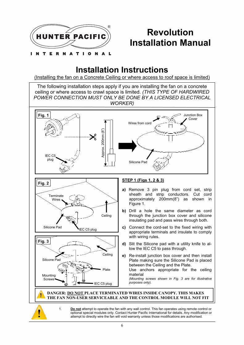
STEP 1 (Figs 1, 2 & 3) a) Remove 3 pin plug from cord set, strip
sheath and strip conductors. Cut cord approximately 200mm(8”) as shown in Figure 1.
b) Drill a hole the same diameter as cord through the junction box cover and silicone insulating pad and pass wires through both.
c) Connect the cord-set to the fixed wiring with appropriate terminals and insulate to comply with wiring rules.
d) Slit the Silicone pad with a utility knife to al-low the IEC C5 to pass through.
e) Re-install junction box cover and then install Plate making sure the Silicone Pad is placed between the Ceiling and the Plate.
Use anchors appropriate for the ceiling material
(Mounting screws shown in Fig. 3 are for illustrative purposes only).
Installation Instructions (Installing the fan on a Concrete Ceiling or where access to roof space is limited)
Fig. 1
Revolution Installation Manual
IEC C5 plug
The following installation steps apply if you are installing the fan on a concrete ceiling or where access to crawl space is limited. (THIS TYPE OF HARDWIRED POWER CONNECTION MUST ONLY BE DONE BY A LICENSED ELECTRICAL
WORKER)
®
Fig. 2
Fig. 3
Wires from cord
1. Do not attempt to operate the fan with any wall control. This fan operates using remote control or optional special modules only. Contact Hunter Pacific International for details. Any modification or attempt to directly wire the fan will void warranty unless those modifications are authorised.
Junction Box Cover
Silicone Pad
Silicone Pad IEC C5 plug
Terminate Wires
Ceiling
Ceiling
Silicone Pad
Plate
IEC C5 plug
Mounting Screws
Appro
x.
200m
m (
8”)
DANGER: DO NOT PLACE TERMINATED WIRES INSIDE CANOPY. THIS MAKES
THE FAN NON-USER SERVICEABLE AND THE CONTROL MODULE WILL NOT FIT
7
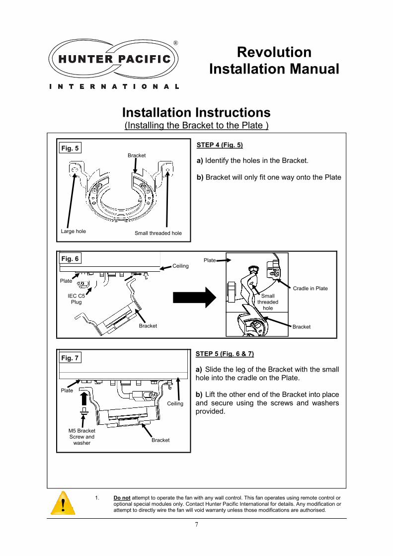
STEP 5 (Fig. 6 & 7)
a) Slide the leg of the Bracket with the small hole into the cradle on the Plate. b) Lift the other end of the Bracket into place and secure using the screws and washers provided.
Installation Instructions (Installing the Bracket to the Plate )
Fig. 5
Revolution Installation Manual
®
Fig. 6
Fig. 7
1. Do not attempt to operate the fan with any wall control. This fan operates using remote control or optional special modules only. Contact Hunter Pacific International for details. Any modification or attempt to directly wire the fan will void warranty unless those modifications are authorised.
Large hole Small threaded hole
Plate
Bracket
IEC C5 Plug
Ceiling
Ceiling
Plate
Bracket
M5 Bracket Screw and
washer
Bracket
Small threaded
hole
Cradle in Plate
Bracket
Plate
STEP 4 (Fig. 5)
a) Identify the holes in the Bracket. b) Bracket will only fit one way onto the Plate
8
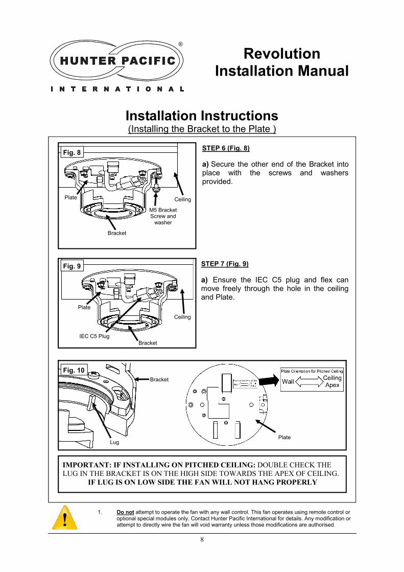
STEP 7 (Fig. 9)
a) Ensure the IEC C5 plug and flex can move freely through the hole in the ceiling and Plate.
Installation Instructions (Installing the Bracket to the Plate )
Fig. 8
Revolution Installation Manual
®
Fig. 9
1. Do not attempt to operate the fan with any wall control. This fan operates using remote control or optional special modules only. Contact Hunter Pacific International for details. Any modification or attempt to directly wire the fan will void warranty unless those modifications are authorised.
Ceiling Plate
Bracket
M5 Bracket Screw and
washer
Ceiling
Plate
Bracket
STEP 6 (Fig. 8)
a) Secure the other end of the Bracket into place with the screws and washers provided.
IEC C5 Plug
IMPORTANT: IF INSTALLING ON PITCHED CEILING: DOUBLE CHECK THE
LUG IN THE BRACKET IS ON THE HIGH SIDE TOWARDS THE APEX OF CEILING.
IF LUG IS ON LOW SIDE THE FAN WILL NOT HANG PROPERLY
Fig. 10
Lug
Bracket
Plate
9
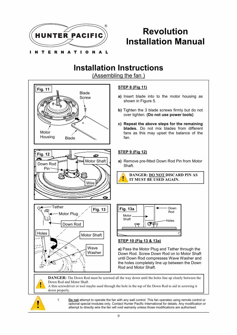
DANGER: The Down Rod must be screwed all the way down until the holes line up clearly between the
Down Rod and Motor Shaft.
A thin screwdriver or tool maybe used through the hole in the top of the Down Rod to aid in screwing it
down properly.
Installation Instructions (Assembling the fan )
Revolution Installation Manual
®
Fig. 13
Fig. 11
Blade
Blade Screw
Motor Housing
Motor Plug
Down Rod
Motor Shaft
Wave Washer
Tether
STEP 8 (Fig 11) a) Insert blade into to the motor housing as
shown in Figure 5. b) Tighten the 3 blade screws firmly but do not
over tighten. (Do not use power tools) c) Repeat the above steps for the remaining
blades. Do not mix blades from different fans as this may upset the balance of the fan.
STEP 10 (Fig 13 & 13a)
a) Pass the Motor Plug and Tether through the Down Rod. Screw Down Rod on to Motor Shaft until Down Rod compresses Wave Washer and the holes completely line up between the Down Rod and Motor Shaft.
1. Do not attempt to operate the fan with any wall control. This fan operates using remote control or optional special modules only. Contact Hunter Pacific International for details. Any modification or attempt to directly wire the fan will void warranty unless those modifications are authorised.
STEP 9 (Fig 12) a) Remove pre-fitted Down Rod Pin from Motor
Shaft.
DANGER: DO NOT DISCARD PIN AS
IT MUST BE USED AGAIN.
Fig. 12
Motor Shaft Down Rod
Pin
Wire
Holes
Fig. 13a Down Rod
Motor Shaft Holes
10
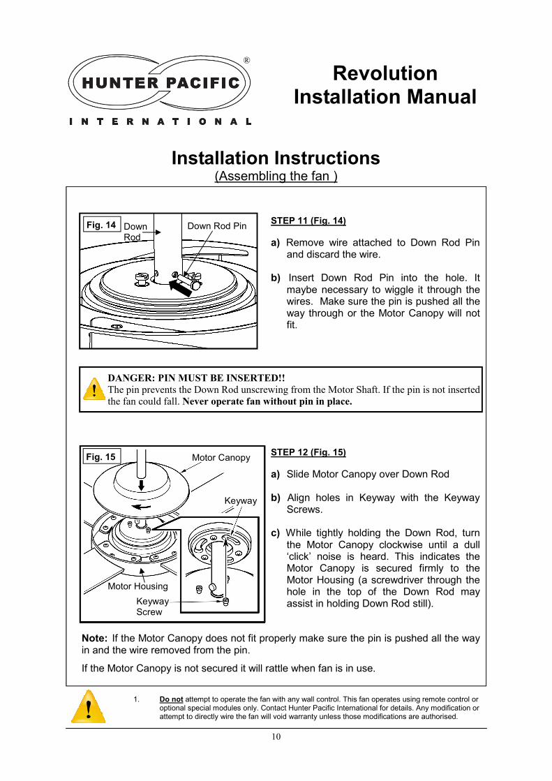
Note: If the Motor Canopy does not fit properly make sure the pin is pushed all the way in and the wire removed from the pin.
If the Motor Canopy is not secured it will rattle when fan is in use.
Installation Instructions (Assembling the fan )
Fig. 1
Revolution Installation Manual
®
Fig. 15
Blade
Motor Housing
Down Rod
Down Rod Pin STEP 11 (Fig. 14)
a) Remove wire attached to Down Rod Pin and discard the wire.
b) Insert Down Rod Pin into the hole. It
maybe necessary to wiggle it through the wires. Make sure the pin is pushed all the way through or the Motor Canopy will not fit.
Keyway
Motor Canopy
Keyway Screw
Motor Housing
STEP 12 (Fig. 15)
a) Slide Motor Canopy over Down Rod b) Align holes in Keyway with the Keyway
Screws. c) While tightly holding the Down Rod, turn
the Motor Canopy clockwise until a dull ‘click’ noise is heard. This indicates the Motor Canopy is secured firmly to the Motor Housing (a screwdriver through the hole in the top of the Down Rod may assist in holding Down Rod still).
1. Do not attempt to operate the fan with any wall control. This fan operates using remote control or optional special modules only. Contact Hunter Pacific International for details. Any modification or attempt to directly wire the fan will void warranty unless those modifications are authorised.
DANGER: PIN MUST BE INSERTED!!
The pin prevents the Down Rod unscrewing from the Motor Shaft. If the pin is not inserted
the fan could fall. Never operate fan without pin in place.
Fig. 14

11
Installation Instructions (Assembling the fan )
Revolution Installation Manual
®
Fig. 16
Motor Plug
Down Rod
Top Canopy
Ball Joint
Tether
STEP 13 (Fig. 16)
a) Slide Top Canopy over Down Rod b) Remove screw from Ball Joint (do not
discard screw) c) Slide Ball Joint over Down Rod
STEP 14 (Fig. 17)
a) Align hole in Ball Joint with hole in Down Rod b) Insert Ball Joint screw through the hole in the
Ball Joint and Down Rod. Use a screwdriver to tighten Ball Joint to Down Rod. Do not over tighten and do not use power tools.
Ball Joint Screw
Ball Joint
Fig. 17
1. Do not attempt to operate the fan with any wall control. This fan operates using remote control or optional special modules only. Contact Hunter Pacific International for details. Any modification or attempt to directly wire the fan will void warranty unless those modifications are authorised.
DANGER: The Ball Joint Screw supports the weight of the fan. Do not replace with a
different type of screw. Do not attempt to install fan if Ball Joint Screw is missing or
damaged.
12
Installation Instructions (Assembling the fan )
Revolution Installation Manual
®
Fig. 18
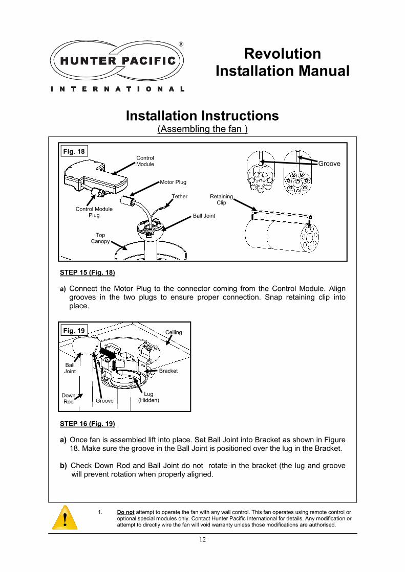
STEP 15 (Fig. 18)
a) Connect the Motor Plug to the connector coming from the Control Module. Align grooves in the two plugs to ensure proper connection. Snap retaining clip into place.
Control Module
Ball Joint
Tether
1. Do not attempt to operate the fan with any wall control. This fan operates using remote control or optional special modules only. Contact Hunter Pacific International for details. Any modification or attempt to directly wire the fan will void warranty unless those modifications are authorised.
Top Canopy
Groove
Fig. 19
Down Rod
Ball Joint Bracket
Ceiling
Groove
Lug (Hidden)
STEP 16 (Fig. 19)
a) Once fan is assembled lift into place. Set Ball Joint into Bracket as shown in Figure 18. Make sure the groove in the Ball Joint is positioned over the lug in the Bracket.
b) Check Down Rod and Ball Joint do not rotate in the bracket (the lug and groove
will prevent rotation when properly aligned.
Motor Plug
Control Module Plug
Retaining Clip
13
Installation Instructions (Assembling the fan )
Revolution Installation Manual
®
1. Do not attempt to operate the fan with any wall control. This fan operates using remote control or optional special modules only. Contact Hunter Pacific International for details. Any modification or attempt to directly wire the fan will void warranty unless those modifications are authorised.
Plate M5 Bracket Screw
Tether
Bracket
Fig. 22
Fig. 20 Fig. 21
Bracket
Plate
M5 Screw & Washer
Tether
Bracket
Plate
M5 Screw & Washer
Tether
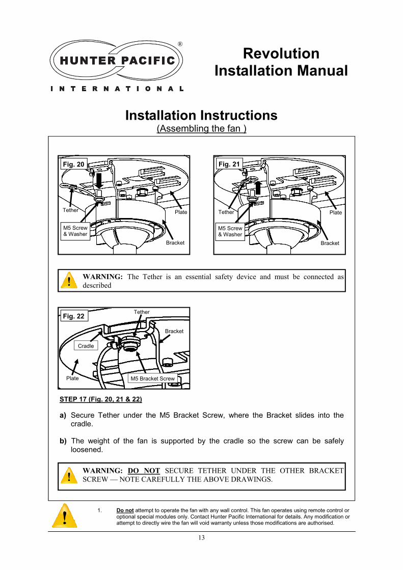
WARNING: The Tether is an essential safety device and must be connected as
described
STEP 17 (Fig. 20, 21 & 22)
a) Secure Tether under the M5 Bracket Screw, where the Bracket slides into the cradle.
b) The weight of the fan is supported by the cradle so the screw can be safely
loosened.
WARNING: DO NOT SECURE TETHER UNDER THE OTHER BRACKET
SCREW — NOTE CAREFULLY THE ABOVE DRAWINGS.
Cradle
14
Installation Instructions (Assembling the fan )
Revolution Installation Manual
®
1. Do not attempt to operate the fan with any wall control. This fan operates using remote control or optional special modules only. Contact Hunter Pacific International for details. Any modification or attempt to directly wire the fan will void warranty unless those modifications are authorised.
Bracket IEC C5 Plug Control
Module
Fig. 23
Fig. 24
Control Module
Bracket Ball Joint
Plate
IEC C5 Plug
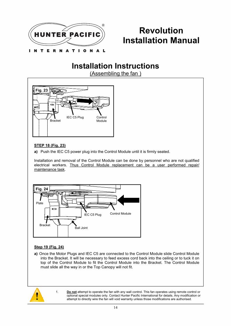
Step 19 (Fig. 24)
a) Once the Motor Plugs and IEC C5 are connected to the Control Module slide Control Module into the Bracket. It will be necessary to feed excess cord back into the ceiling or to tuck it on top of the Control Module to fit the Control Module into the Bracket. The Control Module must slide all the way in or the Top Canopy will not fit.
STEP 18 (Fig. 23)
a) Push the IEC C5 power plug into the Control Module until it is firmly seated. Installation and removal of the Control Module can be done by personnel who are not qualified electrical workers. Thus Control Module replacement can be a user performed repair/maintenance task.
15
Installation Instructions (Assembling the fan )
Revolution Installation Manual
®
1. Do not attempt to operate the fan with any wall control. This fan operates using remote control or optional special modules only. Contact Hunter Pacific International for details. Any modification or attempt to directly wire the fan will void warranty unless those modifications are authorised.
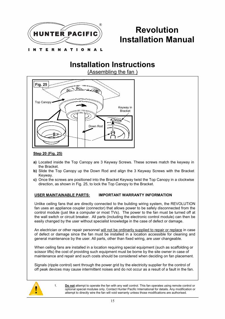
Fig. 25
Step 20 (Fig. 25) a) Located inside the Top Canopy are 3 Keyway Screws. These screws match the keyway in
the Bracket. b) Slide the Top Canopy up the Down Rod and align the 3 Keyway Screws with the Bracket
Keyway. c) Once the screws are positioned into the Bracket Keyway twist the Top Canopy in a clockwise
direction, as shown in Fig. 25, to lock the Top Canopy to the Bracket.
Keyway in Bracket
Top Canopy
Down Rod
USER MAINTAINABLE PARTS: IMPORTANT WARRANTY INFORMATION Unlike ceiling fans that are directly connected to the building wiring system, the REVOLUTION fan uses an appliance coupler (connector) that allows power to be safely disconnected from the control module (just like a computer or most TVs). The power to the fan must be turned off at the wall switch or circuit breaker. All parts (including the electronic control module) can then be easily changed by the user without specialist knowledge in the case of defect or damage. An electrician or other repair personnel will not be ordinarily supplied to repair or replace in case of defect or damage since the fan must be installed in a location accessible for cleaning and general maintenance by the user. All parts, other than fixed wiring, are user changeable. When ceiling fans are installed in a location requiring special equipment (such as scaffolding or scissor lifts) the cost of providing such equipment must be borne by the site owner in case of maintenance and repair and such costs should be considered when deciding on fan placement.
Signals (ripple control) sent through the power grid by the electricity supplier for the control of off peak devices may cause intermittent noises and do not occur as a result of a fault in the fan.
16
REVOLUTION HANDSET BUTTON EXPLANATION
Revolution Installation Manual
®
1. Do not attempt to operate the fan with any wall control. This fan operates using remote control or optional special modules only. Contact Hunter Pacific International for details. Any modification or attempt to directly wire the fan will void warranty unless those modifications are authorised.
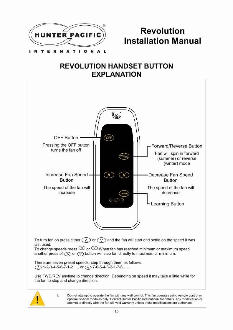
OFF Button
Pressing the OFF button turns the fan off
Increase Fan Speed Button
The speed of the fan will increase
Forward/Reverse Button
Fan will spin in forward (summer) or reverse
(winter) mode
Decrease Fan Speed Button
The speed of the fan will decrease
Learning Button
To turn fan on press either or and the fan will start and settle on the speed it was last used. To change speeds press or When fan has reached minimum or maximum speed another press of or button will step fan directly to maximum or minimum. There are seven preset speeds, step through them as follows:
1-2-3-4-5-6-7-1-2….. or 7-6-5-4-3-2-1-7-6……
Use FWD/REV anytime to change direction. Depending on speed it may take a little while for the fan to stop and change direction.
V
V
V
V
V
V
V
V

17
REVOLUTION CONTROL MODULE AND HANDSET PROGRAMMING
Revolution Installation Manual
®
1. Do not attempt to operate the fan with any wall control. This fan operates using remote control or optional special modules only. Contact Hunter Pacific International for details. Any modification or attempt to directly wire the fan will void warranty unless those modifications are authorised.
MAKE SURE THE WALL SWITCH IS ON OR REMOTE CONTROL WILL NOT WORK
Handset Battery Installation/Replacement Open the battery compartment by sliding the hatch downwards. Gently press the grooved section inwards to disengage latch. UNWRAP THE PLASTIC FROM AROUND NEW BATTERIES. Observe polarity and make sure battery sits properly in recess. Slide hatch back into place.
How To Add a New or Replacement Handset The receiver can learn the identification code for a new handset using the following procedure:
A. Turn off the MAINS POWER to the Control Module for 30 seconds B. Toggle the MAINS POWER ON and OFF as follows (each ON and OFF must be 2
secs).
C. The Control Module will beep four times when it enters program mode. The duration
of each on period and each off period must be 2 seconds. Depending on how accurate the 2 second periods are the Control Module should enter program mode after 3 or 4 cycles of turning the power on/off. If the 2 second periods are too short or too long simply keep toggling power until it does enter program mode.
NOTE: THE MAINS POWER TO THE CONTROL MODULE MUST BE SWITCHED ON-OFF VIA AN EXTERNAL SWITCH. NOT THE BUTTONS ON THE HANDSET.
D. Move the new handset to within 2 metres of the receiver and press “LEARN” button on the handset to add it, or the OFF button to erase all handsets from control module memory (without any handsets the module will beep 4 times when powered)
SEE TERMS AND CONDITIONS OF WARRANTY. YOU WILL BE CHARGED A SERVICE FEE IF THE PRODUCT IS NOT DEFECTIVE OR IS DAMAGED BY POWER SURGES,
LIGHTNING, WEATHER, MISUSE/ABUSE AND SIMILAR SITUATIONS. ALL INSTALLATION INSTRUCTIONS MUST BE FOLLOWED.
IMPORTANT: IF MULTIPLE FANS ARE CONNECTED TO THE SAME FINAL
CIRCUIT OR FED FROM THE SAME POWER SWITCH THEN PROGRAM THE
CONTROL MODULE BY PLUGGING IT INTO A GPO/POWER POINT BEFORE
INSTALLATION.
18
REVOLUTION CONTROL MODULE AND HANDSET PROGRAMMING
Revolution Installation Manual
®
1. Do not attempt to operate the fan with any wall control. This fan operates using remote control or optional special modules only. Contact Hunter Pacific International for details. Any modification or attempt to directly wire the fan will void warranty unless those modifications are authorised.
INSTALLATION INSTRUCTIONS AND RECOMMENDATIONS:
The following statement is required by Australian Standards AS/NZS60335-1 & AS/NZS60335-2-80:
“This appliance is not intended for use by persons (including children) with reduced physical, sensory or mental capabilities, or lack of experience and knowledge, unless they have been given supervision or instruction concerning use of the appliance by a person responsible for their safety. Children should be supervised to ensure that they do not play with the appliance.”
DANGER: Contact with ceiling fan blades can cause serious injury or death. To electricians and installers. The Australian Competition and Consumer Law 2010 mandates consumer protection against defects or poor workmanship in provision of services (such as installing a ceiling fan). To protect yourself and the consumer these instructions must be followed. Failure to do so may result in the consumer making a claim against you for consequential loss or damage.
This remote control system is for use only as intended and connection to equipment other than ceiling fans and associated lighting or installation for purposes outside of those recommended by Hunter Pacific International may void the manufacturers warranty against defects.
The Control Module and Handset portions are for indoor use only or must be protected against moisture.
AS/NZS60335-1:2011 Clause 7.12.2 states the following: “If a stationary appliance is not fitted with a supply cord and a plug, or with other means for disconnection from the supply mains having a contact separation in all poles that provide full disconnection under overvoltage category III conditions, the instructions shall state that means for disconnection must be incorporated in the fixed wiring in accordance with the wiring rules”
The appliance coupler on the end of the supply cord fulfills the requirement for an all pole disconnect device and an all pole switch is not required. So the fan power can be disconnected for user maintenance and handset programming a switch in series with the active (live) must be provided. Connection without this switch may cause undue expense to the customer if a fault develops. Emergency disconnection under fault conditions is not covered by defects warranty.
Placing the receiver in the ceiling cavity may exceed its maximum operating temperature, reduce its life or make it work erratically and may void warranty.
An internal, non-replaceable high rupture capacity fuse is fitted in the receiver. If an in-situ receiver is open circuit then check for a fault in the attached fan or light before replacing and possibly damaging another receiver.
19
Trouble Shooting Tips
Fan does not work
• Check power switch at wall is turned on
• Check remote control handset battery is OK (LED on handset should glow when a button is pressed)
• Does Control Module in the fan’s top canopy beep when a button is pressed? If not, check power is available.
Fan is wobbling
• Check the ball joint slot is locked into the hanger bracket groove.
• Make sure blades are a matching set; the numbers on matching sets of blades should be identical with the numbers varying within 5 grams of each other.
• Check blade screws are tightened firmly (but do not use power tools)
Revolution Installation Manual
®
1. Do not attempt to operate the fan with any wall control. This fan operates using remote control or optional special modules only. Contact Hunter Pacific International for details. Any modification or attempt to directly wire the fan will void warranty unless those modifications are authorised.
20
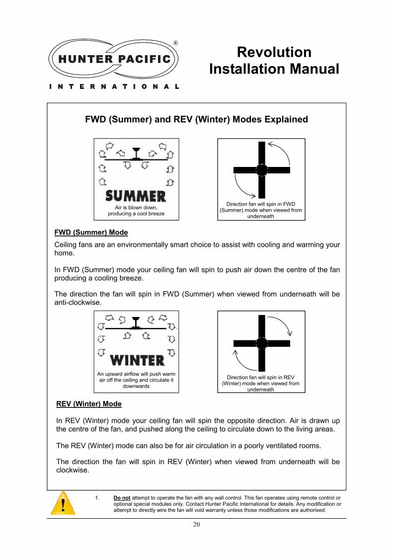
REV (Winter) Mode In REV (Winter) mode your ceiling fan will spin the opposite direction. Air is drawn up the centre of the fan, and pushed along the ceiling to circulate down to the living areas. The REV (Winter) mode can also be for air circulation in a poorly ventilated rooms.
The direction the fan will spin in REV (Winter) when viewed from underneath will be clockwise.
FWD (Summer) Mode
Ceiling fans are an environmentally smart choice to assist with cooling and warming your home. In FWD (Summer) mode your ceiling fan will spin to push air down the centre of the fan producing a cooling breeze.
The direction the fan will spin in FWD (Summer) when viewed from underneath will be anti-clockwise.
FWD (Summer) and REV (Winter) Modes Explained
Revolution Installation Manual
®
1. Do not attempt to operate the fan with any wall control. This fan operates using remote control or optional special modules only. Contact Hunter Pacific International for details. Any modification or attempt to directly wire the fan will void warranty unless those modifications are authorised.
Air is blown down, producing a cool breeze
An upward airflow will push warm air off the ceiling and circulate it
downwards
Direction fan will spin in FWD (Summer) mode when viewed from
underneath
Direction fan will spin in REV (Winter) mode when viewed from
underneath

21
General Maintenance
Changing Remote Batteries: - Batteries used in Handsets will weaken over time and should be replaced every 6 months. Batteries removed from the Handset should be disposed properly and kept out of reach of children.
* Always ensure fan is completely switched off at the wall switch or circuit breaker * Cleaning the Motor Housings: - Motor housings should be regularly cleaned to avoid build up of dust. Dust will attract moisture and condensation leading to corrosion. Use a soft damp (not wet) cloth to remove dust. Cleaning the Blades: - Use a soft damp cloth to remove dirt from blades. Always dry blades after cleaning. Blades should not be left damp or wet as this will damage blade finish or cause corrosion. Always use soft cloths to clean blades and motor housings to avoid scratching painted and plated finishes. Ideally your fan should be cleaned every 3 to 4 months. If removing blades for cleaning then do so for each fan separately, do not mix blades from different fans as this can upset the balance of the fan. To remove the blades, follow in reverse order Steps 8 to 20.
Normal Wear and Tear: - Please note that a ceiling fan travels an enormous distance in the course of its normal operation. Air is abrasive and suspended dust, high humidity and other contamination will cause wear and tear of surfaces. The use of fans under roofed decks and pergolas next to swimming pools and in coastal areas will require increased maintenance due to the presence of chlorides (either as com-mon air borne salt spray or from compounds in pool chemicals) The temperatures attained in the peak of a pitched deck or veranda roof can easily exceed 60-70°C and especially when coupled with chlorides this will increase maintenance require-ments. Even indoors in coastal areas the influx of warm, sea air can accelerate the surface corrosion of metal parts. This can still happen a great many kilometres from the sea. When humidity is high and temperature drops moisture condenses on metal surfaces including ceiling fans. The layer of moisture can be almost microscopic but it will affect the surface by depositing a tiny layer of dissolved salts or airborne acidic compounds and thus eventually leading to corrosion if the product is not properly and regularly cleaned.
LACK OF MAINTENANCE LEADING TO SURFACE CORROSION OR SIMILAR DAMAGE IS NOT COVERED BY WARRANTY.
Revolution Installation Manual
®
1. Do not attempt to operate the fan with any wall control. This fan operates using remote control or optional special modules only. Contact Hunter Pacific International for details. Any modification or attempt to directly wire the fan will void warranty unless those modifications are authorised.
22
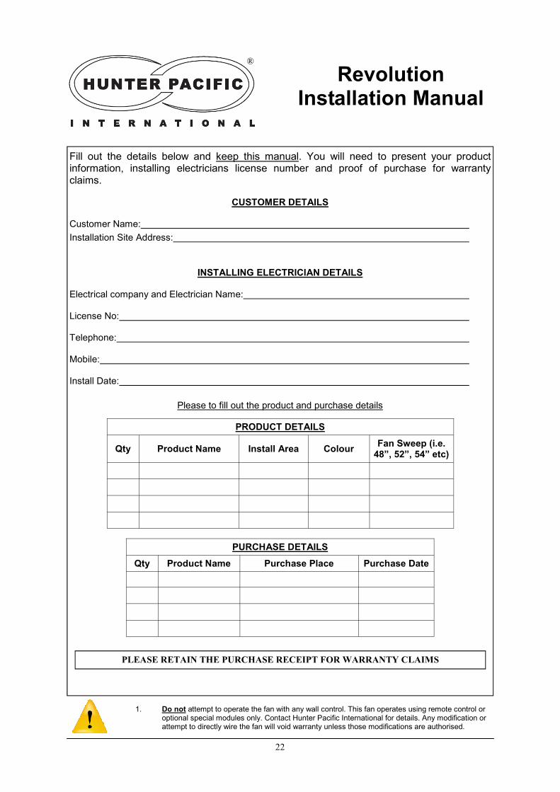
Please to fill out the product and purchase details
Fill out the details below and keep this manual. You will need to present your product information, installing electricians license number and proof of purchase for warranty claims.
CUSTOMER DETAILS
Customer Name:
Installation Site Address:
INSTALLING ELECTRICIAN DETAILS
Electrical company and Electrician Name:
License No:
Telephone:
Mobile:
Install Date:
Revolution Installation Manual
®
1. Do not attempt to operate the fan with any wall control. This fan operates using remote control or optional special modules only. Contact Hunter Pacific International for details. Any modification or attempt to directly wire the fan will void warranty unless those modifications are authorised.
PRODUCT DETAILS
Qty Product Name Install Area Colour Fan Sweep (i.e.
48”, 52”, 54” etc)
PURCHASE DETAILS
Qty Product Name Purchase Place Purchase Date
PLEASE RETAIN THE PURCHASE RECEIPT FOR WARRANTY CLAIMS
23
Warranty periods begin from the day of purchase from an authorised reseller or dealer. Warranty on home builder supplied and installed fans commences when fans are delivered to the home builder or contractor (which generally precedes hand over of the dwelling). Warranty periods are as follows:
• 2 years on customer replaceable electronic modules and components that fail due to defect in materials or workmanship.
• 3 years on mechanical components that that fail due to defect in materials or workmanship (this excludes cosmetic issues and corrosion that occurs due to normal wear and tear).
• 5 years on motor windings and non-replaceable electrical parts. This statement is required by the Australian Consumer Law 2010: “Our goods come with guarantees that cannot be excluded under the Australian Consumer Law. You are entitled to a replacement or refund for a major failure and for compensation for any other reasonably foreseeable loss or dam-age. You are also entitled to have the goods repaired or replaced if the goods fail to be of acceptable quality and the failure does not amount to a major failure.” Please note carefully - If the product is found to be free of defects or the product is not functioning properly as a result of faulty installation or lack of maintenance then Hunter Pacific International Pty Ltd or its service agent reserve the right to charge a service fee to rectify the reported problem. An electrician or other repair personnel will not ordinarily be dispatched to repair or replace parts un-der warranty since the installation instructions state the fan must be installed in a location accessible for cleaning and general maintenance by the user. Plus, unlike ceiling fans that are directly connected to the building wiring system, power can be safely disconnected from the control module (just like a computer or most TVs). After power to the fan is turned off at the wall switch or circuit breaker all parts (including the electronic control module) can then be easily changed by the user without specialist knowledge in the case of any defect or dam-age. Damage caused by incorrect installation, force-majeure, electrical surges, lightning, power grid fluc-tuations, water or alternative power supply sources (such as solar inverters etc.) will not be covered by warranty. This warranty does not cover the product being incorrectly used, physically abused, ac-cidentally damaged or not serviced in accordance with the maintenance instructions.
This product warranty excludes to the extent possible under law any liability for consequential loss or damages directly or indirectly resulting from a faulty ceiling fan or accessory product that is not in-stalled or maintained according to the installation instructions. When installed, maintained and used according to the instructions such loss or damage can be easily avoided or minimised.
Signals (ripple control) sent through the power grid by the electricity supplier for the control of off peak devices may cause intermittent noises and do not occur as a result of a fault in the fan.
When ceiling fans are installed in a location requiring special equipment (such as scaffolding or scis-sor lifts) the cost of providing such equipment must be borne by the site owner in case of mainte-nance and repair and such costs should be considered when deciding on fan placement.
Warranty Terms and Conditions
®
1. Do not attempt to operate the fan with any wall control. This fan operates using remote control or optional special modules only. Contact Hunter Pacific International for details. Any modification or attempt to directly wire the fan will void warranty unless those modifications are authorised.
PLEASE RETAIN THE PURCHASE RECEIPT FOR WARRANTY CLAIMS

24
®
Hunter Pacific International Pty Ltd Head Office: Building 8, 256 New line Road,
New Line Business Park, Dural, NSW, Australia. www.hunterpacific.com.au
ABN 18 063 521 666
National Warranty Line: 1300 360 280 Available Monday to Friday, from 9am to 5pm AEST.