
Power Line Communication Technologies: Modeling · PDF filePRIME is a new NBPLC system, which...
6
Abstract— Power Line Communications is a relatively new area of telecommunication. PLC employs full duplex methods for transmitting data over power lines as medium of transmission of electrical signals over a grid. PLC technologies are used in advanced meter reading, home automation and Public street lighting. Several PLC technologies classified based on the operational frequency range, are explored in this paper. PRIME is a new NBPLC system, which uses OFDM in its physical layer, for power line communication in the last mile. This work also focused on PRIME’s physical specifications, which was modeled in MATLAB/SIMULINK. In this paper, the performance of PRIME when its data is modulated using DQPSK and 4-QAM in four (4) channel models is shown.. Index Terms— OFDM, Power line communications, PRIME, PLC. I. INTRODUCTION ower-line communication is based on electrical signals, carrying information, propagating over the power-line. A communication channel is defined as the physical path between two communication nodes on which the communication signal is propagated [1], [2]. Power line communication (PLC), as the name suggests, provides connectivity using existing power lines as the communications medium. There are many different types of systems (and terminologies) associated with PLC, and nearly as many standards. Furthermore, there are technologies aimed at in-building or in-home use, those aimed at external electrical plant use, and those that support both. External plant applications are considered here, and a full survey even of just these is beyond the scope of this report. PLC systems make up the vast majority of Neighborhood Area Network systems in Europe, and were the dominant solution for early North American systems until the rapidly growing popularity of Radio Frequency systems. Power Line Communications have not been standardized for a long time, but some regulations have been established like CENELEC norm EN 50065-1. Also in existence are standardization for Broadband PLC for in–home PLC–based Local Area Networks and internet access (IEEE P1901.1 [3]), standardization of Narrow–Band PLC for Smart Grid applications. Manuscript received July 18, 2012; revised August 8 2012. A. A. Atayero and A. A. Alatishe are with the Department of Electrical & Information Engineering, Covenant University, PMB 1023 Ota, Ogun State, Nigeria (corresponding author to provide phone: +234-807-886- 6304; e-mail: [email protected]). Y. A. Ivanov is with the Information Security Department, Moscow Technical University of Communication and Informatics, Russia. II. PLC STANDARDS PLC involves the enabling of bidirectional flow of Information; PLC systems have been developed for use in every part of the grid and have been placed in three bandwidth categories [4]. Fig. 1: PLC operational frequency bands. A. ULTRA Narrowband PLC Ultra Narrow Band (UNB) Technologies operate at very low data rate (~100 bps) in the Ultra Low Frequency (0.3- 3kHz) band or in the upper part of the Super Low Frequency (30-300 Hz) band. the earliest PLC systems are ripple control systems, first introduced in the 1930s, and still used in parts of Europe and New Zealand to provide basic low bandwidth direct load control and other telemetry. These use basic modulation schemes on a lower frequency carrier to convey information at a rate of 10 bits per second. Another approach used since the 1970s leverages the fundamental alternating current (AC) frequency (50-60 Hz) as a carrier to transmit information on the power line. As a result, these systems avoid many of the noise and attenuation issues of other PLC technologies (which impose other carrier frequencies) and can be transmitted across long distances and through transformers without repeaters. The leading example of this is Two-Way Automatic Communications System (TWACS – today known as Aclara PLC). These systems also deliver 10 to 100 bits per second data rates. Low-speed PLC systems have been widely deployed for remote meter reading and direct load control applications in North America. For example, Florida Power & Light (FPL) had a long and successful deployment of millions of TWACS-enabled meters and as many as one` million residential load control devices, supporting one of the largest DR programs in the world. However, the performance of these systems inhibits their use as the NAN for more advanced smart metering systems. Aderemi A. Atayero, Adeyemi A. Alatishe, and Yury A. Ivanov, Members, IAENG Power Line Communication Technologies: Modeling and Simulation of PRIME Physical Layer P Proceedings of the World Congress on Engineering and Computer Science 2012 Vol II WCECS 2012, October 24-26, 2012, San Francisco, USA ISBN: 978-988-19252-4-4 ISSN: 2078-0958 (Print); ISSN: 2078-0966 (Online) WCECS 2012
Transcript of Power Line Communication Technologies: Modeling · PDF filePRIME is a new NBPLC system, which...
Abstract— Power Line Communications is a relatively new
area of telecommunication. PLC employs full duplex methods for transmitting data over power lines as medium of transmission of electrical signals over a grid. PLC technologies are used in advanced meter reading, home automation and Public street lighting. Several PLC technologies classified based on the operational frequency range, are explored in this paper. PRIME is a new NBPLC system, which uses OFDM in its physical layer, for power line communication in the last mile. This work also focused on PRIME’s physical specifications, which was modeled in MATLAB/SIMULINK. In this paper, the performance of PRIME when its data is modulated using DQPSK and 4-QAM in four (4) channel models is shown..
Index Terms— OFDM, Power line communications, PRIME, PLC.
I. INTRODUCTION
ower-line communication is based on electrical signals, carrying information, propagating over the power-line. A communication channel is defined as the physical
path between two communication nodes on which the communication signal is propagated [1], [2]. Power line communication (PLC), as the name suggests, provides connectivity using existing power lines as the communications medium. There are many different types of systems (and terminologies) associated with PLC, and nearly as many standards.
Furthermore, there are technologies aimed at in-building or in-home use, those aimed at external electrical plant use, and those that support both. External plant applications are considered here, and a full survey even of just these is beyond the scope of this report. PLC systems make up the vast majority of Neighborhood Area Network systems in Europe, and were the dominant solution for early North American systems until the rapidly growing popularity of Radio Frequency systems. Power Line Communications have not been standardized for a long time, but some regulations have been established like CENELEC norm EN 50065-1. Also in existence are standardization for Broadband PLC for in–home PLC–based Local Area Networks and internet access (IEEE P1901.1 [3]), standardization of Narrow–Band PLC for Smart Grid applications.
Manuscript received July 18, 2012; revised August 8 2012. A. A. Atayero and A. A. Alatishe are with the Department of Electrical
& Information Engineering, Covenant University, PMB 1023 Ota, Ogun State, Nigeria (corresponding author to provide phone: +234-807-886-6304; e-mail: [email protected]).
Y. A. Ivanov is with the Information Security Department, Moscow Technical University of Communication and Informatics, Russia.
II. PLC STANDARDS
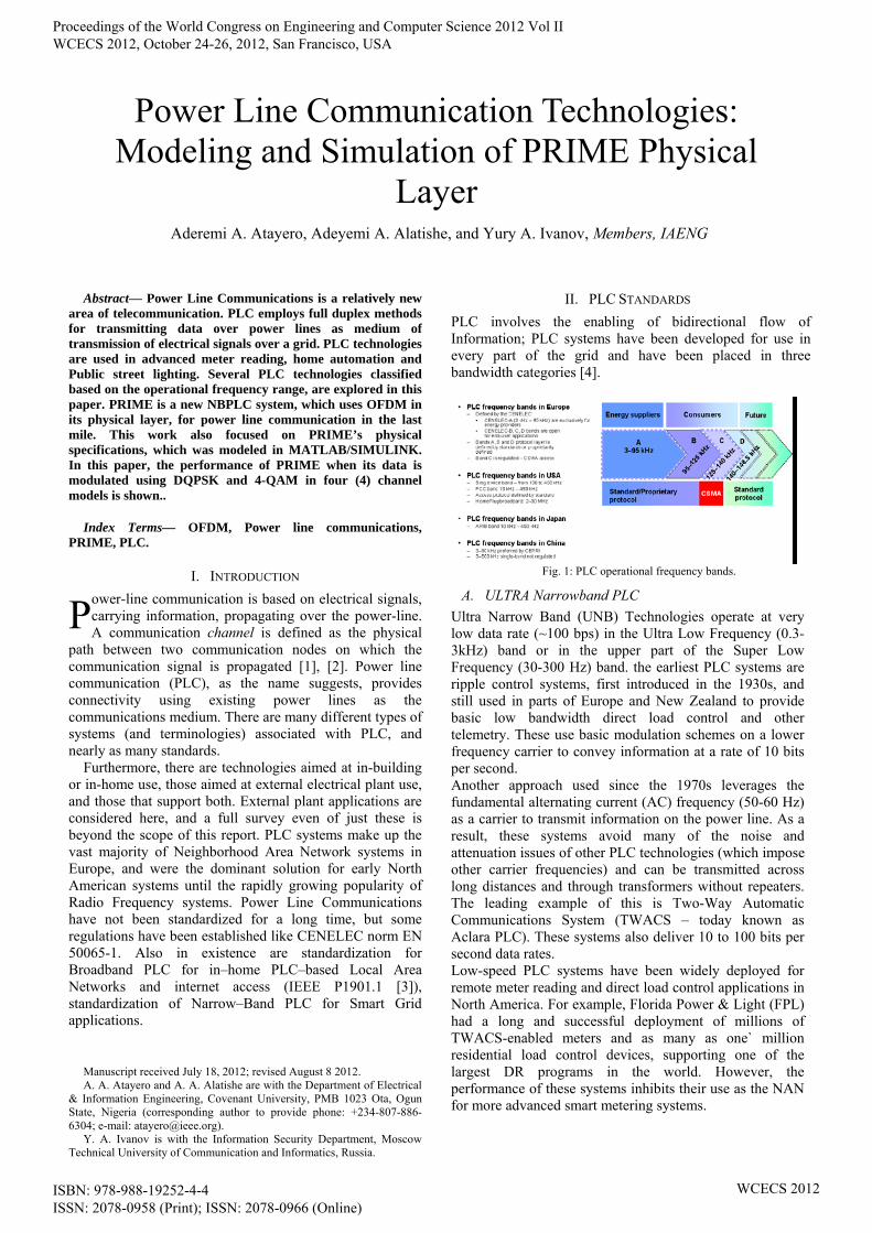
PLC involves the enabling of bidirectional flow of Information; PLC systems have been developed for use in every part of the grid and have been placed in three bandwidth categories [4].
Fig. 1: PLC operational frequency bands.
A. ULTRA Narrowband PLC
Ultra Narrow Band (UNB) Technologies operate at very low data rate (~100 bps) in the Ultra Low Frequency (0.3-3kHz) band or in the upper part of the Super Low Frequency (30-300 Hz) band. the earliest PLC systems are ripple control systems, first introduced in the 1930s, and still used in parts of Europe and New Zealand to provide basic low bandwidth direct load control and other telemetry. These use basic modulation schemes on a lower frequency carrier to convey information at a rate of 10 bits per second. Another approach used since the 1970s leverages the fundamental alternating current (AC) frequency (50-60 Hz) as a carrier to transmit information on the power line. As a result, these systems avoid many of the noise and attenuation issues of other PLC technologies (which impose other carrier frequencies) and can be transmitted across long distances and through transformers without repeaters. The leading example of this is Two-Way Automatic Communications System (TWACS – today known as Aclara PLC). These systems also deliver 10 to 100 bits per second data rates. Low-speed PLC systems have been widely deployed for remote meter reading and direct load control applications in North America. For example, Florida Power & Light (FPL) had a long and successful deployment of millions of TWACS-enabled meters and as many as one` million residential load control devices, supporting one of the largest DR programs in the world. However, the performance of these systems inhibits their use as the NAN for more advanced smart metering systems.
Aderemi A. Atayero, Adeyemi A. Alatishe, and Yury A. Ivanov, Members, IAENG
Power Line Communication Technologies: Modeling and Simulation of PRIME Physical
Layer
P
Proceedings of the World Congress on Engineering and Computer Science 2012 Vol II WCECS 2012, October 24-26, 2012, San Francisco, USA
ISBN: 978-988-19252-4-4 ISSN: 2078-0958 (Print); ISSN: 2078-0966 (Online)
WCECS 2012
B. Broadband ROADBAND PLC
Technologies operating in the High Frequency/Very High Frequency bands (1.8-250 MHz) and having a bit rate ranging from several Mbps to several hundred Mbps. Some examples of BB-PLC technologies are devices conforming to the TIA-1113 HomePlug1.0), IEEE 1901, and ITU-T G.hn (G.9960/G.9961) recommendations [5]. over power line (BPL) systems generally refer to PLC systems supporting data rates over 1 Mbps. Like N-PLC, there is no shortage of BPL systems and proposals. There is a long-running standards war over BPL technology for in-home use. In addition, systems for external MV and LV segments have long been discussed (and provisionally deployed) as another means of providing alternative “last-mile” broadband Internet and voice services [5]. BPL technologies generally operate at carrier frequencies well above the CENELEC bands and therefore experience inconsistent and extremely challenging spectrum characteristics. Not only has reliable communications been hard to achieve, but these systems have also caused significant electromagnetic interference problems. Perhaps the most controversial interference has been with amateur radio operators, who have repeatedly petitioned the FCC to enforce greater regulations on such interference. Additionally, business experiments that had electric utilities offering Internet services to consumers via BPL have failed, with utilities refocusing on their core electrical distribution businesses. One high-profile failure involved Current Group LLC, which was behind a plan to offer broadband service to 2 million Dallas-area homes over Oncor’s electrical network. This plan collapsed in May 2008, with Current Group selling the installed BPL network to Oncor for use in internal backhaul communications. Oncor subsequently replaced the BPL-enabled meters when it embarked on its full-scale RF mesh deployment (supplied by Landis+Gyr). Current Group and other BPL vendors, including Ambient, have reoriented their products toward smart grid applications and no longer emphasize BPL solutions. In-home broadband technologies may be deployed for HAN applications and potentially could be expanded to the external LV segments in the future. However, there are few serious BPL NAN applications currently being deployed.
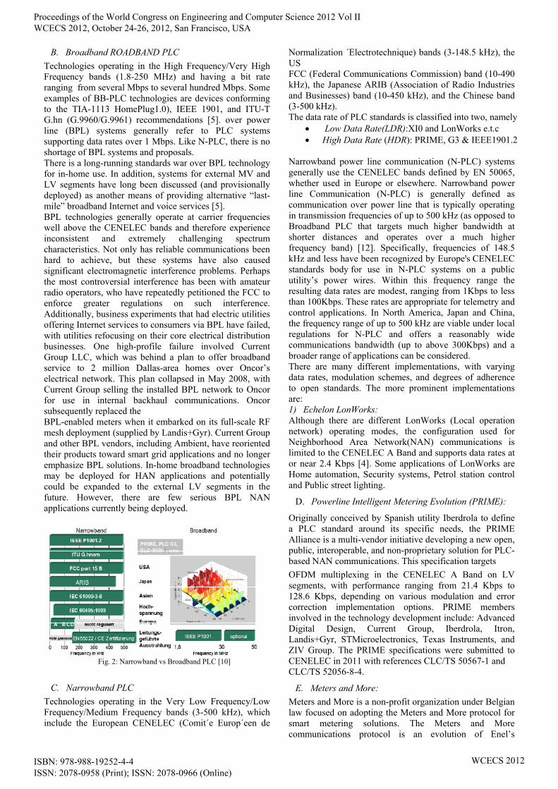
Fig. 2: Narrowband vs Broadband PLC [10]
C. Narrowband PLC
Technologies operating in the Very Low Frequency/Low Frequency/Medium Frequency bands (3-500 kHz), which include the European CENELEC (Comit´e Europ´een de
Normalization ´Electrotechnique) bands (3-148.5 kHz), the US FCC (Federal Communications Commission) band (10-490 kHz), the Japanese ARIB (Association of Radio Industries and Businesses) band (10-450 kHz), and the Chinese band (3-500 kHz). The data rate of PLC standards is classified into two, namely
Low Data Rate(LDR):XI0 and LonWorks e.t.c High Data Rate (HDR): PRIME, G3 & IEEE1901.2
Narrowband power line communication (N-PLC) systems generally use the CENELEC bands defined by EN 50065, whether used in Europe or elsewhere. Narrowband power line Communication (N-PLC) is generally defined as communication over power line that is typically operating in transmission frequencies of up to 500 kHz (as opposed to Broadband PLC that targets much higher bandwidth at shorter distances and operates over a much higher frequency band) [12]. Specifically, frequencies of 148.5 kHz and less have been recognized by Europe's CENELEC standards body for use in N-PLC systems on a public utility’s power wires. Within this frequency range the resulting data rates are modest, ranging from 1Kbps to less than 100Kbps. These rates are appropriate for telemetry and control applications. In North America, Japan and China, the frequency range of up to 500 kHz are viable under local regulations for N-PLC and offers a reasonably wide communications bandwidth (up to above 300Kbps) and a broader range of applications can be considered. There are many different implementations, with varying data rates, modulation schemes, and degrees of adherence to open standards. The more prominent implementations are: 1) Echelon LonWorks: Although there are different LonWorks (Local operation network) operating modes, the configuration used for Neighborhood Area Network(NAN) communications is limited to the CENELEC A Band and supports data rates at or near 2.4 Kbps [4]. Some applications of LonWorks are Home automation, Security systems, Petrol station control and Public street lighting.
D. Powerline Intelligent Metering Evolution (PRIME):
Originally conceived by Spanish utility Iberdrola to define a PLC standard around its specific needs, the PRIME Alliance is a multi-vendor initiative developing a new open, public, interoperable, and non-proprietary solution for PLC-based NAN communications. This specification targets
OFDM multiplexing in the CENELEC A Band on LV segments, with performance ranging from 21.4 Kbps to 128.6 Kbps, depending on various modulation and error correction implementation options. PRIME members involved in the technology development include: Advanced Digital Design, Current Group, Iberdrola, Itron, Landis+Gyr, STMicroelectronics, Texas Instruments, and ZIV Group. The PRIME specifications were submitted to CENELEC in 2011 with references CLC/TS 50567-1 and CLC/TS 52056-8-4.
E. Meters and More:
Meters and More is a non-profit organization under Belgian law focused on adopting the Meters and More protocol for smart metering solutions. The Meters and More communications protocol is an evolution of Enel’s
Proceedings of the World Congress on Engineering and Computer Science 2012 Vol II WCECS 2012, October 24-26, 2012, San Francisco, USA
ISBN: 978-988-19252-4-4 ISSN: 2078-0958 (Print); ISSN: 2078-0966 (Online)
WCECS 2012

Telegestore technology and is a PLC technology. The Physical layer uses BPSK modulation and the logical link control layer (LLC) is based on International Electrotechnical Commission (IEC) 61334-4-32. It uses a table-based data model and an efficient data link layer, leading to short messages (frames) and low error rates to increase overall throughput. It also includes Advanced Encryption Standard (AES) 128 encryption and authentication. Meters and More is an open technology selected for standardization in the OPEN meter project.
F. IEC 61334-5-x Standards:
A number of different implementations (-1, -2, and -4) with different modulation schemes (and hence performance levels) are defined by the IEC and implemented by a number of vendors. The IEC 61334-5-1 specification is part of the Dutch smart metering specification, but has a limited data rate of approximately 300 bits per second. The “-2” specification performance is up to 1,200 bits per second.
G. CENELEC EN 50090 (Konnex/KNX):
A communications protocol managed by the KNX Association for home automation systems and approved as various international, European, and Chinese standards. It is supported over a number of different media, including two PLC profiles, one supporting 1.2 Kbps and the other 2.4 Kbps data rates. Table 1: Categories of Power line Communication
Type of Power Line Communication
Data Rate Grid Segment
Modulation Frequency
Vendor Examples
Low Speed PLC
10-100 bps
MV and LV Segment
50 to 60Hz
Aclara PLC (TWAS)
Narrow band PLC
1-100 Kbps
Mostly LV Only
CENELEC A Band
Echelon, PRIME,G3-PLC.
Broadband over Power Line(BPL)
1-2 Mbps
Mostly LV only
OFDM at Higher bands
Current Group Ambient Corp
In Europe, the communications spectrum offered by power lines is regulated by the European Committee for Electrotechnical Standardization (CENELEC) and is defined by EN 50065 (“Signaling on low voltage electrical installations in the frequency range 3 KHz to 148.5 KHz”). In this specification, spectrum is divided into four bands:
3 KHz to 8 KHz, reserved for use by energy providers and customers’ premises
A Band (9-95 KHz), reserved for use by energy providers
B Band (95-125 KHz), reserved for use by energy providers’ customers
C Band (125-140 KHz), reserved for use by energy providers’ customers and regulated as to channel access techniques
D Band (140-148.5 KHz), reserved for use by energy providers’ customers
In the United States, a single wide band is defined as 150 KHz to 450 KHz with no significant restrictions. Additionally, some systems are targeted for use on the low voltage (LV) portion of the grid (from transformer to the premises) and/or the medium voltage (MV) portion of the grid (neighborhood regional distribution to local transformers).
Fig. 3: PLC modem frequency bands vs. bit rate
III. PLC APPLICATIONS
Most PLC Smart Grid applications on the Low Voltage side are in the area of Automatic Meter Reading/ Advance Metering Infrastructure (AMR/AMI), In addition to basic one-way meter reading (AMR), AMI systems provide two-way communications that can be used to exchange information with customer devices and systems. Furthermore, AMI enables utilities to interact with meters and allows customer awareness of electricity pricing on a real-time basis [8]. Vehicle-to-Grid communications, Demand Side Management, and in-home energy management.
IV. MULTI-CARRIER MODULATION
Orthogonal frequency division multiplexing (OFDM) uses multiple orthogonal subcarriers to transmit data, it provides increased robustness against frequency selective fading and narrowband interference, and is efficient in dealing with multi-path delay spread. To achieve this, OFDM splits high-rate data streams into lower rate streams, which are then transmitted simultaneously over several sub-carriers. The subcarriers are themselves modulated by using Phase Shift Keying (PSK) or Quadrature Amplitude Modulation (QAM) and are subsequently carried on a high frequency carrier. This is similar to conventional Frequency Division Multiplexing (FDM) or Sub-Carrier Multiplexing, except for the stringent requirement of orthogonality between the sub-carriers. Sub-carrier orthogonality can be viewed in two ways, namely the time, and the frequency domains. OFDM is processor intensive because the basic OFDM signal is formed using the Inverse Fast Fourier Transform (IFFT), adding a cyclic extension and performing windowing to get steeper spectral roll off. In the receiver, the sub-carriers are demodulated by using Fast Fourier Transformation (FFT). The requirement for the intensive computations accounts for the complexity of OFDM transmitters and receivers. In comparison to single-carrier modulation systems, OFDM is more sensitive to Frequency offset and phase noise. Furthermore, OFDM has a relatively large peak-to-average power ratio, which reduces the power efficiency of the RF amplifier. OFDM is already used in many access network technologies including High-bit-rate, Digital Subscriber Lines (HDSL), and Asymmetric Digital Subscriber Lines (ADSL). It is discussed in detail in [6].
Proceedings of the World Congress on Engineering and Computer Science 2012 Vol II WCECS 2012, October 24-26, 2012, San Francisco, USA
ISBN: 978-988-19252-4-4 ISSN: 2078-0958 (Print); ISSN: 2078-0966 (Online)
WCECS 2012
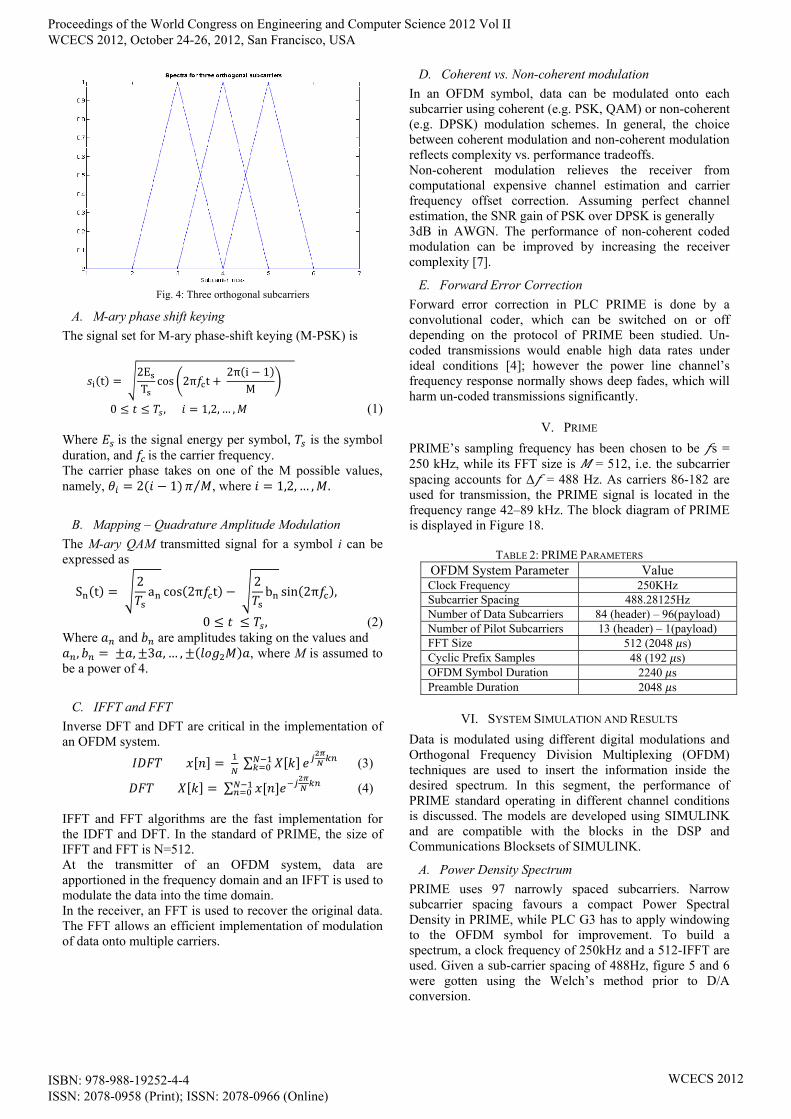
Fig. 4: Three orthogonal subcarriers
A. M-ary phase shift keying
The signal set for M-ary phase-shift keying (M-PSK) is
t 2ET
cos 2π t 2π i 1
M
0 , 1,2, … , (1) Where is the signal energy per symbol, is the symbol duration, and is the carrier frequency. The carrier phase takes on one of the M possible values, namely, 2 1 ⁄ , where 1,2, … , .
B. Mapping – Quadrature Amplitude Modulation
The M-ary QAM transmitted signal for a symbol i can be expressed as
S t 2a cos 2π t
2b sin 2π ,
0 , (2) Where and are amplitudes taking on the values and , , 3 , … , , where M is assumed to
be a power of 4.
C. IFFT and FFT
Inverse DFT and DFT are critical in the implementation of an OFDM system.
∑ (3)
∑ (4) IFFT and FFT algorithms are the fast implementation for the IDFT and DFT. In the standard of PRIME, the size of IFFT and FFT is N=512. At the transmitter of an OFDM system, data are apportioned in the frequency domain and an IFFT is used to modulate the data into the time domain. In the receiver, an FFT is used to recover the original data. The FFT allows an efficient implementation of modulation of data onto multiple carriers.
D. Coherent vs. Non-coherent modulation
In an OFDM symbol, data can be modulated onto each subcarrier using coherent (e.g. PSK, QAM) or non-coherent (e.g. DPSK) modulation schemes. In general, the choice between coherent modulation and non-coherent modulation reflects complexity vs. performance tradeoffs. Non-coherent modulation relieves the receiver from computational expensive channel estimation and carrier frequency offset correction. Assuming perfect channel estimation, the SNR gain of PSK over DPSK is generally 3dB in AWGN. The performance of non-coherent coded modulation can be improved by increasing the receiver complexity [7].
E. Forward Error Correction
Forward error correction in PLC PRIME is done by a convolutional coder, which can be switched on or off depending on the protocol of PRIME been studied. Un-coded transmissions would enable high data rates under ideal conditions [4]; however the power line channel’s frequency response normally shows deep fades, which will harm un-coded transmissions significantly.
V. PRIME
PRIME’s sampling frequency has been chosen to be s = 250 kHz, while its FFT size is = 512, i.e. the subcarrier spacing accounts for Δ = 488 Hz. As carriers 86-182 are used for transmission, the PRIME signal is located in the frequency range 42–89 kHz. The block diagram of PRIME is displayed in Figure 18.
TABLE 2: PRIME PARAMETERS OFDM System Parameter Value Clock Frequency 250KHz Subcarrier Spacing 488.28125Hz Number of Data Subcarriers 84 (header) – 96(payload) Number of Pilot Subcarriers 13 (header) – 1(payload) FFT Size 512 (2048 s) Cyclic Prefix Samples 48 (192 s) OFDM Symbol Duration 2240 s Preamble Duration 2048 s
VI. SYSTEM SIMULATION AND RESULTS
Data is modulated using different digital modulations and Orthogonal Frequency Division Multiplexing (OFDM) techniques are used to insert the information inside the desired spectrum. In this segment, the performance of PRIME standard operating in different channel conditions is discussed. The models are developed using SIMULINK and are compatible with the blocks in the DSP and Communications Blocksets of SIMULINK.
A. Power Density Spectrum
PRIME uses 97 narrowly spaced subcarriers. Narrow subcarrier spacing favours a compact Power Spectral Density in PRIME, while PLC G3 has to apply windowing to the OFDM symbol for improvement. To build a spectrum, a clock frequency of 250kHz and a 512-IFFT are used. Given a sub-carrier spacing of 488Hz, figure 5 and 6 were gotten using the Welch’s method prior to D/A conversion.
Proceedings of the World Congress on Engineering and Computer Science 2012 Vol II WCECS 2012, October 24-26, 2012, San Francisco, USA
ISBN: 978-988-19252-4-4 ISSN: 2078-0958 (Print); ISSN: 2078-0966 (Online)
WCECS 2012
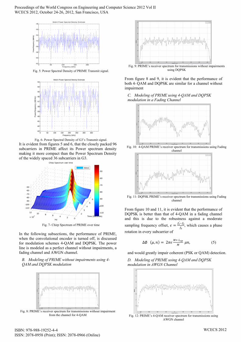
Fig. 5: Power Spectral Density of PRIME Transmit signal.
Fig. 6- Power Spectral Density of G3’s Transmit signal.
It is evident from figures 5 and 6, that the closely packed 96 subcarriers in PRIME affect its Power spectrum density making it more compact than the Power Spectrum Density of the widely spaced 36 subcarriers in G3.
Fig. 7- Chirp Spectrum of PRIME over time
In the following subsections, the performance of PRIME, when the convolutional encoder is turned off, is discussed for modulation schemes 4-QAM and DQPSK. The power line is modeled as a perfect channel without impairments, a fading channel and AWGN channel.
B. Modeling of PRIME without impairments using 4-QAM and DQPSK modulation
Fig. 8: PRIME’s receiver spectrum for transmissions without impairment
from the channel for 4-QAM
Fig. 9: PRIME’s receiver spectrum for transmissions without impairments
using DQPSK
From figure 8 and 9, it is evident that the performance of both 4- QAM and DQPSK are similar for a channel without impairment
C. Modeling of PRIME using 4-QAM and DQPSK modulation in a Fading Channel
Fig. 10: 4-QAM PRIME’s receiver spectrum for transmissions using Fading
channel
Fig. 11: DQPSK PRIME’s receiver spectrum for transmissions using Fading
channel
From figure 10 and 11, it is evident that the performance of DQPSK is better than that of 4-QAM in a fading channel and this is due to the robustness against a moderate
sampling frequency offset, ′
, which causes a phase
rotation in every subcarrier of
∆∅ , 2
, (5)
and would greatly impair coherent (PSK or QAM) detection.
D. Modeling of PRIME using 4-QAM and DQPSK modulation in AWGN Channel
Fig. 12: PRIME’s 4-QAM receiver spectrum for transmissions using
AWGN channel
0 50 100 150 200-62
-60
-58
-56
-54
-52
-50
-48
Frequency (kHz)
Pow
er/fre
quen
cy (dB
/Hz)
Welch Power Spectral Density Estimate
0 50 100 150 200 250 300 350-63
-62
-61
-60
-59
-58
-57
-56
-55
-54
-53
Frequency (kHz)
Pow
er/f
requ
ency
(dB
/Hz)
Welch Power Spectral Density Estimate
2
3
4
5
6
x 10-3
024681012
x 104
-110
-100
-90
-80
-70
-60
-50
Time (Seconds)
Chirp Spectrum over time
Hz
data1
-110
-100
-90
-80
-70
-60
-50
Proceedings of the World Congress on Engineering and Computer Science 2012 Vol II WCECS 2012, October 24-26, 2012, San Francisco, USA
ISBN: 978-988-19252-4-4 ISSN: 2078-0958 (Print); ISSN: 2078-0966 (Online)
WCECS 2012

Fig. 13: PRIME’s DQPSK receiver spectrum for transmissions using
AWGN channel.
From figures 12 and 13, it is evident that the performance of both 4- QAM and DQPSK are similar for AWGN channel, but 4-QAM performs slightly better. Also it is evident that their performance in AWGN channel is close to their performance in a perfect channel (Channel without impairments).
E. Modeling of PRIME using 4-QAM and DQPSK modulation in AWGN + Dispersive Channel
Fig. 14: PRIME’s 4-QAM receiver spectrum for transmissions using
AWGN + Dispersive Channel
Fig. 15: PRIME’s DQPSK receiver spectrum for transmissions using AWGN +
Dispersive Channel
The performance of both 4- QAM and DQPSK are similar for AWGN+Dispersive channel, but 4-QAM performs slightly better (Fig. 14 and 15).
F. BER Plots
Fig. 16: BER plot for DQPSK in AWGN
Fig. 17: BER Plot for 4-QAM
VII. CONCLUSION
Since the development and research on the subject of Power line communications is relatively new, the primary reason for this paper was to serve as a reference for PLC technologies, products and standards. The power line technology is getting stabilized and attracting many industry leading vendors. The power line enables the electric utilities to provide other services to the customer like broadband internet access along with traditional electric power. Also the physical layer of PRIME PLC which is based on CP-OFDM is explored. We illustrated the performance of PRIME when it is modulated using a coherent (4-QAM) or non-coherent (DQPSK) modulation scheme under three-channel condition without Forward error corrections.
REFRENCES [1] J.B. Anderson, "Digital Transmission Engineering", IEEE Press,
1998. [2] J.G. Proakis, "Digital Communications", McGraw-Hill, 1995. [3] Martin Hoch, “Comparison of PLC G3 and PRIME,” IEEE
International Symposium on Power Line Communications and Its Applications, 2011.
[4] S. Galli, A. Scaglione, and Z. Wang, “For the grid and through the grid: The role of power line communications in the smart grid,” Proc. IEEE, vol. 99, no. 6, pp. 998-1027, 2011.
[5] D. Clark, “Powerline communications: finally ready for prime time?” IEEE Internet Computing, vol. 2, no. 1, pp. 10 – 11, Jan. 1998.
[6] Alan C. Brooks and Stephen J. Hoelzer “Design and Simulation of Orthogonal Frequency Division Multiplexing (OFDM) Signaling” May 15, 2001.
[7] M. Nassar et al, “Local Utility Powerline Communication in the 3-500kHz band: Channel Impairments, Noise and Standards,” IEEE signal processing magazine, January 2012.
[8] “Report to NIST on the Smart Grid Interoperability Standards Roadmap,” Electric Power Research Institute (EPRI), Tech. Rep., June, 2009.
[9] J. Domingo, S. Alexandres, C. Rodriguez-Morcillo, “PRIME Performance in Power Line Communication Channel,” in IEEE Intl. Symposium on Power Line Communications and Its Applications (ISPLC), 2011. available at http://en.wikipedia.org/wiki/LonWorks
[10] DLC-VIT4IP_Distribution Line Carrier von der Niederspannung bis zu Umspannwerk.pdf available at: http://qr.net/eeplc
Fig. 18: Block Diagram of PRIME (according to [9]).
Proceedings of the World Congress on Engineering and Computer Science 2012 Vol II WCECS 2012, October 24-26, 2012, San Francisco, USA
ISBN: 978-988-19252-4-4 ISSN: 2078-0958 (Print); ISSN: 2078-0966 (Online)
WCECS 2012