Power headroom report-based uplink power control in · PDF fileRESEARCH Open Access Power...
13
RESEARCH Open Access Power headroom report-based uplink power control in 3GPP LTE-A HetNet Woon Kim, Zeeshan Kaleem and KyungHi Chang * Abstract In a 3rd Generation Partnership Project Long Term Evolution-Advanced (3GPP LTE-A) uplink, user equipment (UE) has a maximum transmission power limit defined by the UE power class. Generally, the cell edge UE has a higher probability to be constrained by the maximum transmission power level owing to the compensation of the large pathloss. When the UE transmission power is constrained by the maximum level, allocating a higher number of physical resource blocks (PRBs) than the UE power capability can afford will reduce the transmission power to be allocated per PRB, resulting in inefficient use of power resources. To avoid this power inefficiency, the uplink transmission power can be controlled according to the number of PRBs allocated using the power headroom report-based power efficient resource allocation (PHR-PERA) scheme proposed in this paper. Furthermore, adaptive open-loop power control (OL-PC) based on the signal-to-interference-plus-noise ratio (SINR) and the uplink interference is used to improve the cell capacity. By the uplink power control employing the proposed PHR-PERA scheme, the macro and femto UE throughputs were increased by 49.9 and 5 %, respectively, compared to the case of conventional fractional power control (FPC). Additional gains of 21.9 and 4.8 % for macro and femto UE throughputs, respectively, were achieved by adaptive OL-PC. The performance of fast closed-loop power control (CL-PC) based on the received SINR is also evaluated in this paper. The simulation results demonstrate that CL-PC supports OL-PC by compensating the fading effect for the UE uplink SINR to meet the target SINR. Keywords: Uplink power control, Power headroom report, Heterogeneous networks, 3GPP LTE-A 1 Introduction In a 3rd Generation Partnership Project Long Term Evolution-Advanced (3GPP LTE-A) uplink, the orthog- onality provided by single carrier-frequency division multiple access (SC-FDMA) removes intra-cell interfer- ence—i.e., the interference between users in the same cell [1]. However, the inter-cell interference problem remains to be solved because the band allocated to a user in a cell can be used by another user in any of the neighboring cells. In a conventional homogeneous net- work—i.e., a network based on macro cells only—frac- tional power control (FPC) is used to cope with inter- cell interference [1, 2]. The impact of the FPC scheme on the signal-to-interference-plus-noise ratio (SINR) was evaluated in [3, 4] in detail. The FPC scheme partially compensates for the pathloss such that users with high pathloss will operate at a low SINR requirement, thus reducing interference caused to the neighboring cells. In the overload indicator (OI)-based uplink power control proposed in [5], the base station measures the uplink interference and sends the OI to the neighboring base stations to broadcast its interference situation. Based on the number of OIs received, the target’ s received power is dynamically adjusted to control the uplink transmis- sion power and avoid system interference. The latest evolution of cellular networks—i.e., heteroge- neous networks (HetNet)—has been well acknowledged to meet the increasing demand for data traffic. In HetNet, there is a possibility of deploying the picocells or femto- cells with macrocells as one of the candidate for small cells. The picocells’ deployment is the same as the macro- cells’ deployment, that is, they are deployed by telecom operators after doing proper planning in order to reduce the inter-cell interference. However, unplanned user de- ployed femtocell deployments lead to severe inter-cell interference in the aggressive frequency reuse scheme and result in system performance degradation. Allocating different frequency bands to the macro and femtocell by * Correspondence: [email protected] Department of Electronic Engineering, Inha University, Incheon, Korea © 2015 Kim et al. Open Access This article is distributed under the terms of the Creative Commons Attribution 4.0 International License (http://creativecommons.org/licenses/by/4.0/), which permits unrestricted use, distribution, and reproduction in any medium, provided you give appropriate credit to the original author(s) and the source, provide a link to the Creative Commons license, and indicate if changes were made. Kim et al. EURASIP Journal on Wireless Communications and Networking (2015) 2015:233 DOI 10.1186/s13638-015-0466-3
Transcript of Power headroom report-based uplink power control in · PDF fileRESEARCH Open Access Power...

Kim et al. EURASIP Journal on Wireless Communicationsand Networking (2015) 2015:233 DOI 10.1186/s13638-015-0466-3
RESEARCH Open Access
Power headroom report-based uplinkpower control in 3GPP LTE-A HetNet
Woon Kim, Zeeshan Kaleem and KyungHi Chang*Abstract
In a 3rd Generation Partnership Project Long Term Evolution-Advanced (3GPP LTE-A) uplink, user equipment (UE)has a maximum transmission power limit defined by the UE power class. Generally, the cell edge UE has a higherprobability to be constrained by the maximum transmission power level owing to the compensation of the largepathloss. When the UE transmission power is constrained by the maximum level, allocating a higher number ofphysical resource blocks (PRBs) than the UE power capability can afford will reduce the transmission power to beallocated per PRB, resulting in inefficient use of power resources. To avoid this power inefficiency, the uplinktransmission power can be controlled according to the number of PRBs allocated using the power headroomreport-based power efficient resource allocation (PHR-PERA) scheme proposed in this paper. Furthermore, adaptiveopen-loop power control (OL-PC) based on the signal-to-interference-plus-noise ratio (SINR) and the uplinkinterference is used to improve the cell capacity. By the uplink power control employing the proposed PHR-PERAscheme, the macro and femto UE throughputs were increased by 49.9 and 5 %, respectively, compared to the caseof conventional fractional power control (FPC). Additional gains of 21.9 and 4.8 % for macro and femto UEthroughputs, respectively, were achieved by adaptive OL-PC. The performance of fast closed-loop power control(CL-PC) based on the received SINR is also evaluated in this paper. The simulation results demonstrate that CL-PCsupports OL-PC by compensating the fading effect for the UE uplink SINR to meet the target SINR.
Keywords: Uplink power control, Power headroom report, Heterogeneous networks, 3GPP LTE-A
1 IntroductionIn a 3rd Generation Partnership Project Long TermEvolution-Advanced (3GPP LTE-A) uplink, the orthog-onality provided by single carrier-frequency divisionmultiple access (SC-FDMA) removes intra-cell interfer-ence—i.e., the interference between users in the samecell [1]. However, the inter-cell interference problemremains to be solved because the band allocated to auser in a cell can be used by another user in any of theneighboring cells. In a conventional homogeneous net-work—i.e., a network based on macro cells only—frac-tional power control (FPC) is used to cope with inter-cell interference [1, 2]. The impact of the FPC schemeon the signal-to-interference-plus-noise ratio (SINR) wasevaluated in [3, 4] in detail. The FPC scheme partiallycompensates for the pathloss such that users with highpathloss will operate at a low SINR requirement, thusreducing interference caused to the neighboring cells. In
* Correspondence: [email protected] of Electronic Engineering, Inha University, Incheon, Korea
© 2015 Kim et al. Open Access This article is dInternational License (http://creativecommons.oreproduction in any medium, provided you givthe Creative Commons license, and indicate if
the overload indicator (OI)-based uplink power controlproposed in [5], the base station measures the uplinkinterference and sends the OI to the neighboring basestations to broadcast its interference situation. Based onthe number of OIs received, the target’s received poweris dynamically adjusted to control the uplink transmis-sion power and avoid system interference.The latest evolution of cellular networks—i.e., heteroge-
neous networks (HetNet)—has been well acknowledged tomeet the increasing demand for data traffic. In HetNet,there is a possibility of deploying the picocells or femto-cells with macrocells as one of the candidate for smallcells. The picocells’ deployment is the same as the macro-cells’ deployment, that is, they are deployed by telecomoperators after doing proper planning in order to reducethe inter-cell interference. However, unplanned user de-ployed femtocell deployments lead to severe inter-cellinterference in the aggressive frequency reuse scheme andresult in system performance degradation. Allocatingdifferent frequency bands to the macro and femtocell by
istributed under the terms of the Creative Commons Attribution 4.0rg/licenses/by/4.0/), which permits unrestricted use, distribution, ande appropriate credit to the original author(s) and the source, provide a link tochanges were made.

Kim et al. EURASIP Journal on Wireless Communications and Networking (2015) 2015:233 Page 2 of 13
using fractional frequency reuse schemes [6] can be one ofthe solutions to prevent the severe inter-cell interference;however, the goal of using the aggressive frequency reusescheme is to provide the spectral efficiency under thecondition of bandwidth limited situation. Similarly, theinter-cell cooperation scheme such as muting the basestation requires the exchange of the control informationthat gives the overhead resulting in spectral inefficiency[7]. Therefore, in this paper, all the cells are using thesame frequency band to provide spectral efficiency; theuplink power control is used to mitigate the severe inter-ference situation of HetNet. In [8], the cell-specific uplinkpower control scheme was proposed considering theHetNet environment. It is verified that by using a separateset of uplink power control parameters such as targetreceived power for macro- and femtocells, it is possible toincrease the average femtocell capacity and coverage with-out jeopardizing the performance of macro user equip-ment (MUE). The aggregated resource usage of femtouser equipments (FUEs) was used to control the FUEtransmission power in [9]. As the aggregated resourceusage increases, FUE transmission power is suppressed tomaintain the uplink throughput of macro users. In [10], thetarget received power is controlled based on the interfer-ence generated to neighboring cells by exchanging theclosed-loop commands under the HetNet environment.The exchange of the interference state between the cellsallows the base station to send a power control commandto the user equipment (UE).However, less literature has considered the bandwidth
allocated to the user for controlling the uplink transmis-sion power. The allocated bandwidth can be representedas the number of PRBs allocated to the user, and themore PRBs are allocated, the more UE transmissionpower is required. Because the UE has the transmissionpower constraint [11], allocating more number of PRBsthan the UE power capability can afford will reduce thetransmission power allocated per PRB, which is alsoreferred to as spectral density (PSD). This causes ineffi-cient use of power resources. The UE transmitting withmaximal power can also cause severe inter-cell interfer-ence with neighboring cells. In the 3GPP LTE-A system,the UE can inform the base station of its transmissionpower state by using the parameter called power head-room (PH). In this paper, the power headroom report-based power-efficient resource allocation (PHR-PERA)scheme is proposed in order for the base station to con-sider the UE transmission power state while allocatingPRBs. Eventually, the UE transmission power can becontrolled by the number of PRBs allocated by using theproposed PHR-PERA scheme. By employing the proposedscheme, reduction in the PSD can be avoided by allocatingthe UE with the number of PRBs that the UE power cap-ability can afford. Furthermore, adaptive open-loop power
control (OL-PC) based on the SINR and the uplink inter-ference averaged over a certain period is used to optimizecell capacity.The rest of the paper is organized as follows: “System
model” section describes the system model that includesthe network setup and the channel model. In “Generalpower control mechanism in 3GPP LTE-A uplink” sec-tion, the general 3GPP LTE-A uplink power controlmechanism is described. “Proposed uplink power controlprocedure for 3GPP LTE-A system” section explains theproposed uplink power control procedure, including re-source allocation, OL-PC, and closed-loop power control(CL-PC). In “Performance evaluation” section, the per-formance of the proposed uplink power control schemeis evaluated using system-level simulations. Finally, con-clusions are drawn in “Conclusions” section.
2 System model2.1 Network setupFor the data transmission in the 3GPP LTE-A uplink,each user is allocated a certain number of PRBs. OnePRB, which is the smallest radio resource unit, has a sizeof 180 kHz in the frequency domain and 0.5 ms in thetime domain, allowing 50 PRBs to be utilized in a 10-MHz system bandwidth [6].In this paper, a one-tier HetNet environment with
seven eNode B (eNB) sites is considered. The center cellis the region of interest and consists of eNBs, HomeeNode B (HeNBs), MUEs, and FUEs. A 5 × 5 grid modelthat is one of the valid HeNB urban deployment modelsis considered in each sector. It is composed of 25 adja-cent apartments that are 10 × 10 m in size. The deploy-ment of the HeNBs is random in each cell. Thus, thereis a possibility of deployment of HeNBs at the cell-edge.This deployment results in the severe interference fromFUEs to the uplink service of MUEs, especially at thecell-edge.There are seven different kinds of uplink interference
in the 3GPP LTE-A HetNet which consists of macro andfemtocells. Figure 1 describes the uplink interferencescenario in the general HetNet environment. Interfer-ence scenario numbers 1 to 3 are uplink interference atthe eNB, caused by the FUE in the same macrocellcoverage and the MUE and FUE in the neighboringmacrocell coverage. Moreover, interference scenarionumbers 4 to 7 are uplink interference at the HeNBcaused by the MUE and FUE in the same macrocellcoverage and MUE and FUE in the neighboring macro-cell coverage. In 3GPP LTE-A HetNet environment, theinterference caused to the eNB by the FUEs in the samemacro cell can be considered as the major interferencewhich degrades the MUE performance.The uplink SINRs observed on PRBs nm and nf by
MUE um and FUE uf, respectively, can be expressed as

1st Tier
eNB
eNB
eNB
HeNB
FUE
MUE
Interference Signal
Desired Signal
FUE in the same macro cell to the serving eNBMUE in the neighbor macro cell to the serving eNBFUE in the neighbor macro cell to the serving eNBMUE in the same macro cell to the serving HeNB in the same macro cellFUE of the neighbor HeNB in the macro cell to the serving HeNBMUE in the neighbor macro cell to the serving HeNBFUE in the neighbor macro cell to the serving HeNB
Interference Scenario
Fig. 1 Uplink interference scenario in HetNet
Kim et al. EURASIP Journal on Wireless Communications and Networking (2015) 2015:233 Page 3 of 13
SINRnmum ¼ Gnm
umpnmum
Inmum þ η
SINRnfuf ¼
Gnfuf p
nfuf
Infuf þ η
;
8>>><>>>:
ð1Þ
where pnmum and pnfuf are the transmission power from
MUE um and FUE uf to eNB m and HeNB f on PRBs nmand nf, respectively. Gnm
um is the channel gain betweeneNB m and MUE um on PRB nm, and G
nfuf is the channel
gain between HeNB f and FUE uf on PRB nf. The totalaggregated interferences Inmum and I
nfuf received by eNB um
and HeNB uf, respectively, are given as
Inmum ¼X
i∈M;i≠m
Gnmui p
nmi þ
Xj∈F
Gnmuj p
nmj
Infuf ¼
Xi∈M
Gnfui p
nfi þ
Xj∈F; j≠f
Gnfuj p
nfj
:
8>><>>:
ð2Þ
2.2 Channel modelThe channel gain represents the propagation loss thatoccurs when the signal travels from the transmitter tothe receiver. It can be calculated as the antenna gainminus the losses, which include pathloss, shadowing,and fading.The pathloss between the eNB and the MUE is defined
in Eq. 3. The pathloss between the indoor UE and theoutdoor base station includes additional wall loss of20 dB. The simplified pathloss model for dense urban
deployment of HeNBs and a FUE is defined in Eq. 4,where R is the distance between the eNB and the MUEin meters.
PL dBð Þ ¼ 15:3 þ 37:6 log10R; ð3ÞPL dBð Þ ¼ 127þ 30 log10 R=1000ð Þ: ð4Þ
Shadowing is caused when the obstacles are in thepaths between the UEs and the base station. It is mod-eled by using lognormal distribution with a mean of0 dB and standard deviation of 4 dB for the link betweenthe HeNB and the UE [12]. For other interference links,the standard deviation is 10 dB, and the inter-site correl-ation value is 0.5 [13].Fast fading is responsible for the short-term signal
variations that can occur owing to the mobility of theUEs or other reflectors [14]. In this paper, fast fading isgenerated according to the 3GPP LTE-A Ped B channelmodel.
3 General power control mechanism in 3GPPLTE-A uplinkIn a 3GPP LTE-A uplink, data are transmitted by thephysical uplink shared channel (PUSCH) whose trans-mission power can be calculated as
PPUSCH ¼ minPmax;10 log10 MPUSCHð Þ þ P0 þ α⋅PLþ ΔMCS ið Þ þ f ið Þ|fflfflfflfflfflfflfflfflfflfflffl{zfflfflfflfflfflfflfflfflfflfflffl}
closed‐loop
8>>><>>>:
9>>>=>>>;;
ð5Þwhere Pmax is the maximum allowable UE transmissionpower defined as 23 dBm according to [11]. MPUSCH isthe number of PRBs allocated to the UE. The more PRBsare allocated to the UE, the greater UE transmissionpower required. P0 is the target received power, α is thepathloss compensation factor, and PL is the pathlossbetween the UE and its serving base station. ΔMCS andf(i) are the CL-PC parameters that represent the modu-lation and coding scheme (MCS)-dependent parameterand the transmission power control (TPC) command,respectively. The overall uplink power control procedureis described below.
3.1 Open-loop power controlThe OL-PC parameters are the target received power P0,pathloss compensation factor α, and pathloss betweenthe UE and its base station. By controlling the OL-PCparameters, the PSD can be determined as [3]
PSDtx ¼ P0 þ α⋅PL: ð7ÞThe target received power can be calculated as the sum
of P0_NOMINAL and P0_UE, which are the cell-specific and
Kim et al. EURASIP Journal on Wireless Communications and Networking (2015) 2015:233 Page 4 of 13
UE-specific values, respectively. The uplink transmissionpower is set based on the downlink pathloss estimate tocompensate for the uplink pathloss. How much pathlossto be compensated is determined by the value of α, whichcan be selected from {0, 0.4, 0.5, 0.6, 0.7, 0.8, 0.9, 1} [15].
3.2 Closed-loop power controlIn CL-PC, the base station directly participates in settingthe UE transmission power by using MCS-dependentvalue ΔMCS and TPC command f(i) [15].ΔMCS is the value determined by the transport format
selected by the base station for uplink transmission andcan be calculated as
ΔMCS ¼ 10 log10 2BPRE⋅Ks−1� �
⋅βPUSCHoffset
� �: ð8Þ
The bits per resource element (BPRE) are calculatedas OCQI/NRE where OCQI is the number of CQI bits andNRE is the number of the resource element (RE). Ks isgiven by the parameter deltaMCS-Enabled provided by
the higher layer as 1.25. The βCQIoffset value corresponding
to the different MCS levels is provided by the table in[15]. High MCS levels require high transmission power.In situations such that the UE is in the power-limitedstate, the transmission power can be decreased by lower-ing the MCS level.TPC command f(i) is sent by the base station to the
UE in order to increase or decrease the transmissionpower, based on the comparison of the received SINRand the target SINR. f(i) is expressed as
f ið Þ ¼ f i−1ð Þ þ δPUSCH i−4ð Þ ð9Þwhere i denotes ith subframe and (i–4) denotes the
four subframe delay from subframe i. δPUSCH is the TPCcommand value, which is defined in Table 1.
3.3 Power headroom reportPower headroom (PH) is reported by the UE to the basestation to broadcast how much power the UE requiredin the previous subframe. Therefore, the base stationmay perform the effective link adaptation and the re-source allocation for uplink transmission using the PHreport. By referring to the PH report, the base stationcan determine whether the UE should be allocated withfewer PRBs compared to the number allocated in theprevious subframe. The negative PH value implies that
Table 1 TPC command value
TPC command field in DCI format 0/3/4 TPC command values [dB]
0 −1
1 0
2 1
3 3
the UE was in the power limited state in the previoussubframe. The PH has a range of [−23, 40] dB with 1-dBincrements [16] and is calculated as
PH ¼ Pmax− 10 log10 MPUSCHð Þ þ P0 þ α⋅PLþ ΔMCS þ f ið Þ� �ð10Þ
3.4 Shortcomings of existing power control schemes in3GPP LTE-A uplinkIn the conventional power control scheme, the numberof PRBs to be allocated to the user is determined by theUE traffic and MCS level. However, for the UE with thehigher probability to send with the maximum power(i.e., cell edge user), the transmission power for eachPRB will be reduced as the number of allocated PRBsexceeds the amount that is affordable by the powercapability. The power loss in each PRB reduces thetransmission power efficiency. At the same time, the UEtransmitting with maximal transmission power causessevere inter-cell interference to the neighboring cells,resulting in performance degradation in the uplink.Therefore, the base station must consider the UE trans-mission power state while allocating the PRBs in orderto avoid inefficient transmission power utilization andsevere inter-cell interference caused by the maximumtransmission power of the UE. In the proposed PHR-PERA scheme in this paper, the base station uses the PHreport, which can reflect the UE transmission powerstate in the previous subframe in allocating the appropri-ate number of PRBs to the UE in order to achieveenhanced performance due to improved power efficiencyand less interference.
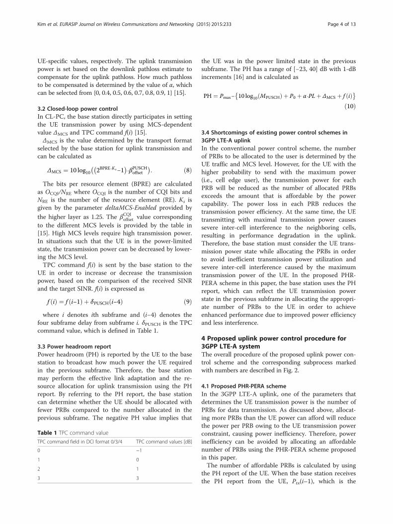
4 Proposed uplink power control procedure for3GPP LTE-A systemThe overall procedure of the proposed uplink power con-trol scheme and the corresponding subprocess markedwith numbers are described in Fig. 2.
4.1 Proposed PHR-PERA schemeIn the 3GPP LTE-A uplink, one of the parameters thatdetermines the UE transmission power is the number ofPRBs for data transmission. As discussed above, allocat-ing more PRBs than the UE power can afford will reducethe power per PRB owing to the UE transmission powerconstraint, causing power inefficiency. Therefore, powerinefficiency can be avoided by allocating an affordablenumber of PRBs using the PHR-PERA scheme proposedin this paper.The number of affordable PRBs is calculated by using
the PH report of the UE. When the base station receivesthe PH report from the UE, Ptx(i–1), which is the
a
c
d e
b
Fig. 2 Proposed PHR-based uplink power control procedure: a overall uplink power control procedure, b PHR-PERA procedure, c OL-PC parametersetting procedure, d MCS level selection procedure, e TPC command value selection procedure
Kim et al. EURASIP Journal on Wireless Communications and Networking (2015) 2015:233 Page 5 of 13
transmission power of the UE in the previous subframe,is calculated as
Ptx i−1ð Þ ¼ Pmax−PH; ð11Þ
where Ptx(i–1) can also be represented by Eq. 12,whereas PSDtx and ~M are the per-PRB power and the
number of PRBs allocated to the UE in the previous sub-frame, respectively.
Ptx i−1ð Þ ¼ PSDtx þ 10 log ~M� � ð12Þ
By using Eqs. 11 and 12, PSDtx can be expressed as
Kim et al. EURASIP Journal on Wireless Communications and Networking (2015) 2015:233 Page 6 of 13
PSDtx ¼ Pmax−PH−10 log ~M� �
: ð13ÞThe UE transmission power for the current subframe
is determined by Eq. 7 while satisfying
10 log MPHRð Þ þ PSDtx þ ΔTF ið Þ þ f ið Þ≤Pmax; ð14Þwhere MPHR is the number of PRBs that the UE powercapability can afford. By substituting Eq. 13 into Eq. 14,MPHR can be calculated as
MPHR≤10
Pmax−PSDtx−ΔTF ið Þ−f ið Þ10
¼ 10
PHþ 10 log ~M� �
−ΔTF ið Þ−f ið Þ10
ð15Þ
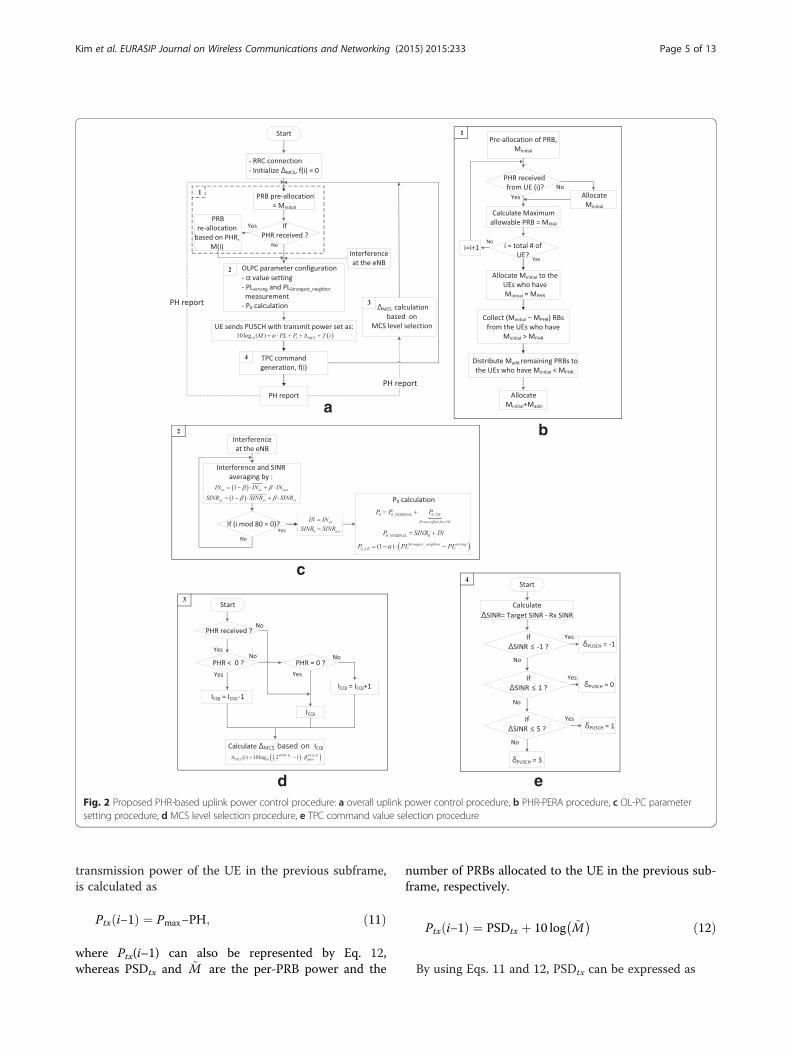
Once the affordable number of PRBs is decided, thenext procedure is divided into two stages—the pre-allocation and re-allocation stages. In the pre-allocationstage, the round robin (RR) scheduling algorithm [17],
Table 2 PHR-PERA algorithm
which is one of the conventional 3GPP LTE-A uplinkresource allocation schemes, is used to determine theinitial number of PRBs to be allocated to the UE. Afterthe pre-allocation, the re-allocation is performed usingMPHR calculated in the base station based on the PH re-ported by the UE. In the re-allocation, the number ofPRBs determined in the pre-allocation stage is allocatedto the UE that has not reported its PH to the basestation. Otherwise, the base station will allocate the PRBto the UE based on MPHR. The PHR-PERA algorithmoperates as shown in Table 2.The procedure of the proposed PHR-PERA scheme is
described in the flowchart in Fig. 2b.
4.2 Adaptive open-loop power controlIn our proposed uplink power control procedure, α iskept constant in order to concentrate on verifying theperformance of P0 variation. PL is calculated accordingto the pathloss model discussed in “Channel model”

Kim et al. EURASIP Journal on Wireless Communications and Networking (2015) 2015:233 Page 7 of 13
section. P0 is calculated by adding the cell-specificP0_NOMINAL and UE-specific P0_UE, and it is broadcastedto the UE using system information block 2 (SIB2),whose broadcasting period can be selected from {8, 16,32, 64, 128, 256, 512} radio frames [15]. In this paper,eight radio frames—i.e., 80 ms—is selected as the SIB2broadcasting period in order to vary P0 dynamically. Theprocedure for setting P0 is described below.According to [18], P0_NOMINAL can be determined as
P0NOMINAL ¼ SINR0 þ IN; ð16Þ
where SINR0 is the cell-specific target SINR and IN isthe received interference and noise. Because P0 is up-dated every 80 ms based on the periodicity of SIB2,SINR0 can be determined by averaging the receivedSINR at the base station over the updating period. IN isalso the average interference at the base station to reflectthe dynamic interference situation. SINR0 and IN can beaveraged using the higher-layer filter defined in [16] asEqs. 17 and 18, respectively:
INav ¼ 1−βð Þ⋅INav þ β⋅INinst ð17Þ
SINRav ¼ 1−βð Þ⋅SINRav þ β⋅SINRinst ð18Þ
where β is the forgetting factor with the value of 0.01.Because the cell-specific P0_NOMINAL considers the re-
ceived SINR and the received interference, the UE-specific P0_UE considers the pathloss of each UE. In the3GPP LTE-A system, the UE receives the referencesignal reference power (RSRP) broadcasted by the neigh-boring base stations. The UE can then report the re-ceived RSRP to its serving base station. The serving basestation can determine the pathloss between its UE andthe neighboring base station by using the reportedRSRP. The UE-specific P0_UE can then be calculated as
P0UE ¼ 1−αð Þ⋅ PLStrongestneighbor−PLserving� �
; ð19Þ
where PLserving is the pathloss between the UE and itsserving base station and PLStrongest_neighbor is the stron-gest pathloss between the UE and the neighboring basestation. If the pathloss of the strongest neighbor issufficiently larger than PLserving, the UE can increase itspower by setting a higher target SINR, giving the posi-tive offset of P0_UE; otherwise, the UE can decrease itspower by lowering its target SINR using the negative off-set of P0_UE. The overall flowchart of setting the P0parameter is shown in Fig. 2c.
4.3 PHR and SINR-based closed-loop power controlIn the CL-PC, the UE transmission power is con-trolled by MCS-dependent parameter ΔMCS and TPCcommand f(i).
Because the higher MCS level is used for the PUSCHtransmission, more transmission power is required. Thebase station can first determine the MCS level based onthe received SINR. The selection criteria of the MCSlevel based on the SINR value is seen in [19]. However,the base station may perform effective link adaptation byusing the PH report as discussed earlier. The UE trans-mission power level in the previous subframe can bereflected in the MCS selection by using the PH report. Ifthe UE reports the positive PH, the base station can con-sider that it is possible for the UE to increase its trans-mission power. In this case, the MCS level that wasoriginally selected based on the received SINR can beincreased by one. If no power headroom is reported orthe reported power headroom value is 0, then there willbe no variation in the MCS level selected based on thereceived SINR. If the UE reports negative PH, the basestation can consider the UE transmission power to beset as maximum. In this case, the MCS level can bedecreased by one in order to reduce the UE transmissionpower. Once the proper MCS level for the PUSCHtransmission is selected, ΔMCS can be calculated usingEq. 8. The MCS selection procedure by the base stationis illustrated by the flowchart in Fig. 2d.The selection of the TPC command value is based on
the comparison of the received SINR and the targetSINR. If the received SINR cannot meet the target SINR,the base station sends the UE the positive TPC com-mand value to increase the transmission –power—other-wise, vice versa. The criteria for selecting the TPC valueare as follows [20]:
if ΔSINR dB½ � <¼ –1; then –1 is sentelse if –1 < ΔSINR dB½ � <¼ 1; then 0 is sentelse if 1 < ΔSINR dB½ � <¼ 3; then 1 is sentelse if ΔSINR dB½ � <¼ 5; then 3 is sent
ð20Þ
The TPC command value selection procedure can beseen in the flowchart of Fig. 2e.
5 Performance evaluation5.1 Simulation parametersTo evaluate the performance of the proposed PHR-baseduplink power control procedure, system-level simulation isperformed under the network scenario defined in “Systemmodel” section. The system parameters are shown inTable 3. The simulation results are plotted by using theMATLAB-based uplink system level simulator, which isdesigned by considering the LTE simulation guidelines [12].The maximum number of users in a cell when the
fading exists is defined as Eq. 30 in [21]. Therefore,by considering this constraint, in this paper, we se-lected 15 FUEs and 8 MUEs in a macrocell based on

Table 3 Simulation parameters
Parameter Value
Carrier frequency 1.76 GHz
Bandwidth 10 MHz
Number of PRBs 48 + 2 (control channel)
Cellular layout of macrocells Hexagonal grid, 3 sector cells/eNB
Number of sites 7 cells (21 sectors)
Region of interest (ROI) Center cell (3 sectors)
Inter-site distance 500 m
HeNB deployment model 5 × 5 grid model
Number of HeNBs/macrocell 5
Number of MUEs/eNBs 8
Number of FUEs/HeNBs 3
UE maximum transmission power (Pmax) 23 dBm
Traffic model Full buffer
Simulation duration 30 drops, 500 TTIs
Kim et al. EURASIP Journal on Wireless Communications and Networking (2015) 2015:233 Page 8 of 13
the simulation result shown in Fig. 3, where the le-gend (x, y) stands for (MUEs, FUEs). According toFig. 3, the best performance in macrocell sumthroughput is attained by using 8 MUEs and 15 FUEsin a macrocell. As the number of MUE increases,more users will contend on the same resource blocks,and thus less MUE sum throughput is resulted. Asthe number of MUE decreases, some of the resourceblocks will be wasted as no users will use it. Thus,there is a tradeoff between the number of MUEs pereNB and sum throughput.
0
20
40
60
80
100
120
140
(6,15) (8,15) Number of M
Sum
Thr
ough
put [
Mbp
s]
Fig. 3 Selection of the best number of MUE and FUE
5.2 Evaluation of the proposed PHR-based uplink powercontrol procedure5.2.1 Initial parameter setting in conventional open-looppower controlIn this section, the effect of the FPC scheme and itsP0 parameter setting is evaluated in order to deter-mine the initial OL-PC parameters. P0 and α param-eter of both the MUE and the FUE were set to−80 dBm and 0.8 [8], respectively. However, the OL-PC parameters can be set differently for the macro-and femtocells in the HetNet environment to increase
(10,15) (12,15)UEs and FUEs
Sum Throughput of MacrocellsSum Throughput of Femtocells
Kim et al. EURASIP Journal on Wireless Communications and Networking (2015) 2015:233 Page 9 of 13
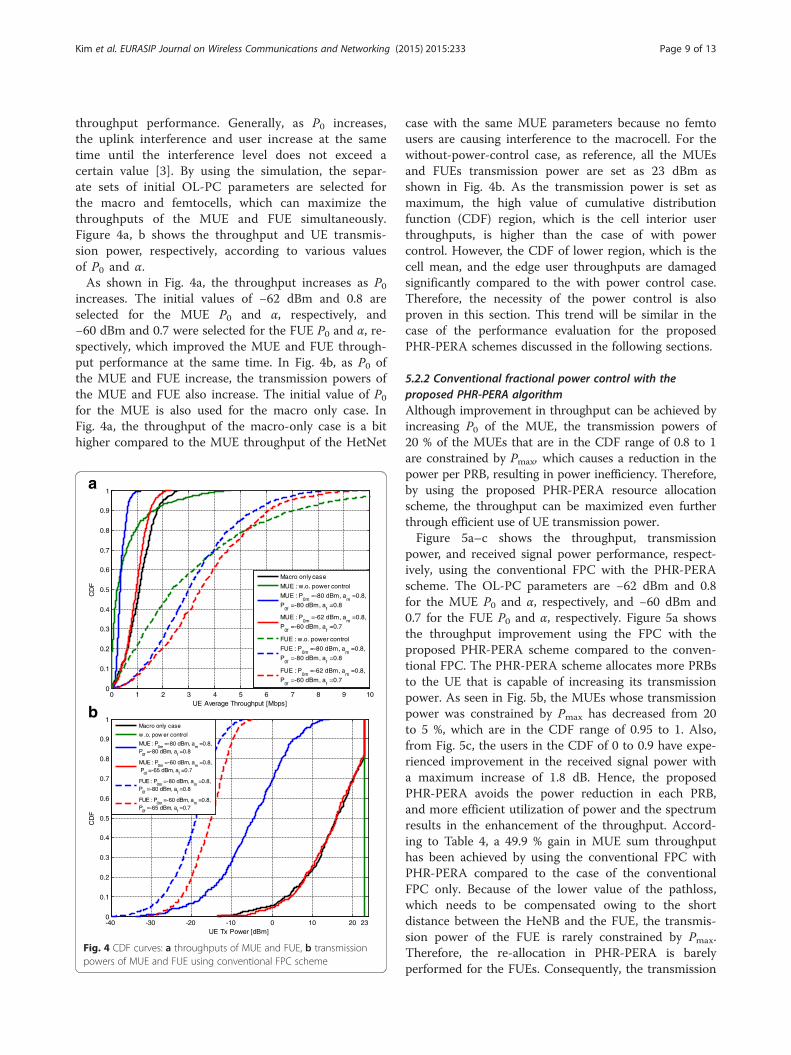
throughput performance. Generally, as P0 increases,the uplink interference and user increase at the sametime until the interference level does not exceed acertain value [3]. By using the simulation, the separ-ate sets of initial OL-PC parameters are selected forthe macro and femtocells, which can maximize thethroughputs of the MUE and FUE simultaneously.Figure 4a, b shows the throughput and UE transmis-sion power, respectively, according to various valuesof P0 and α.As shown in Fig. 4a, the throughput increases as P0
increases. The initial values of −62 dBm and 0.8 areselected for the MUE P0 and α, respectively, and−60 dBm and 0.7 were selected for the FUE P0 and α, re-spectively, which improved the MUE and FUE through-put performance at the same time. In Fig. 4b, as P0 ofthe MUE and FUE increase, the transmission powers ofthe MUE and FUE also increase. The initial value of P0for the MUE is also used for the macro only case. InFig. 4a, the throughput of the macro-only case is a bithigher compared to the MUE throughput of the HetNet
0 1 2 3 4 5 6 7 8 9 100
0.1
0.2
0.3
0.4
0.5
0.6
0.7
0.8
0.9
1
UE Average Throughput [Mbps]
CD
F
b
Macro only case
MUE : w.o. power control
MUE : P0m
=-80 dBm, am
=0.8,
P0f
=-80 dBm, af =0.8
MUE : P0m
=-62 dBm, am
=0.8,
P0f
=-60 dBm, af =0.7
FUE : w.o. power control
FUE : P0m
=-80 dBm, am
=0.8,
P0f
=-80 dBm, af =0.8
FUE : P0m
=-62 dBm, am
=0.8,
P0f
=-60 dBm, af =0.7
-40 -30 -20 -10 0 10 20 230
0.1
0.2
0.3
0.4
0.5
0.6
0.7
0.8
0.9
1
UE Tx Power [dBm]
CD
F
Macro only case
w .o. pow er control
MUE : P0m
=-80 dBm, am =0.8,
P0f =-80 dBm, a
f =0.8
MUE : P0m
=-60 dBm, am =0.8,
P0f =-65 dBm, a
f =0.7
FUE : P0m
=-80 dBm, am =0.8,
P0f =-80 dBm, a
f =0.8
FUE : P0m
=-60 dBm, am =0.8,
P0f =-65 dBm, a
f =0.7
Fig. 4 CDF curves: a throughputs of MUE and FUE, b transmissionpowers of MUE and FUE using conventional FPC scheme
case with the same MUE parameters because no femtousers are causing interference to the macrocell. For thewithout-power-control case, as reference, all the MUEsand FUEs transmission power are set as 23 dBm asshown in Fig. 4b. As the transmission power is set asmaximum, the high value of cumulative distributionfunction (CDF) region, which is the cell interior userthroughputs, is higher than the case of with powercontrol. However, the CDF of lower region, which is thecell mean, and the edge user throughputs are damagedsignificantly compared to the with power control case.Therefore, the necessity of the power control is alsoproven in this section. This trend will be similar in thecase of the performance evaluation for the proposedPHR-PERA schemes discussed in the following sections.
5.2.2 Conventional fractional power control with theproposed PHR-PERA algorithmAlthough improvement in throughput can be achieved byincreasing P0 of the MUE, the transmission powers of20 % of the MUEs that are in the CDF range of 0.8 to 1are constrained by Pmax, which causes a reduction in thepower per PRB, resulting in power inefficiency. Therefore,by using the proposed PHR-PERA resource allocationscheme, the throughput can be maximized even furtherthrough efficient use of UE transmission power.Figure 5a–c shows the throughput, transmission
power, and received signal power performance, respect-ively, using the conventional FPC with the PHR-PERAscheme. The OL-PC parameters are −62 dBm and 0.8for the MUE P0 and α, respectively, and −60 dBm and0.7 for the FUE P0 and α, respectively. Figure 5a showsthe throughput improvement using the FPC with theproposed PHR-PERA scheme compared to the conven-tional FPC. The PHR-PERA scheme allocates more PRBsto the UE that is capable of increasing its transmissionpower. As seen in Fig. 5b, the MUEs whose transmissionpower was constrained by Pmax has decreased from 20to 5 %, which are in the CDF range of 0.95 to 1. Also,from Fig. 5c, the users in the CDF of 0 to 0.9 have expe-rienced improvement in the received signal power witha maximum increase of 1.8 dB. Hence, the proposedPHR-PERA avoids the power reduction in each PRB,and more efficient utilization of power and the spectrumresults in the enhancement of the throughput. Accord-ing to Table 4, a 49.9 % gain in MUE sum throughputhas been achieved by using the conventional FPC withPHR-PERA compared to the case of the conventionalFPC only. Because of the lower value of the pathloss,which needs to be compensated owing to the shortdistance between the HeNB and the FUE, the transmis-sion power of the FUE is rarely constrained by Pmax.Therefore, the re-allocation in PHR-PERA is barelyperformed for the FUEs. Consequently, the transmission
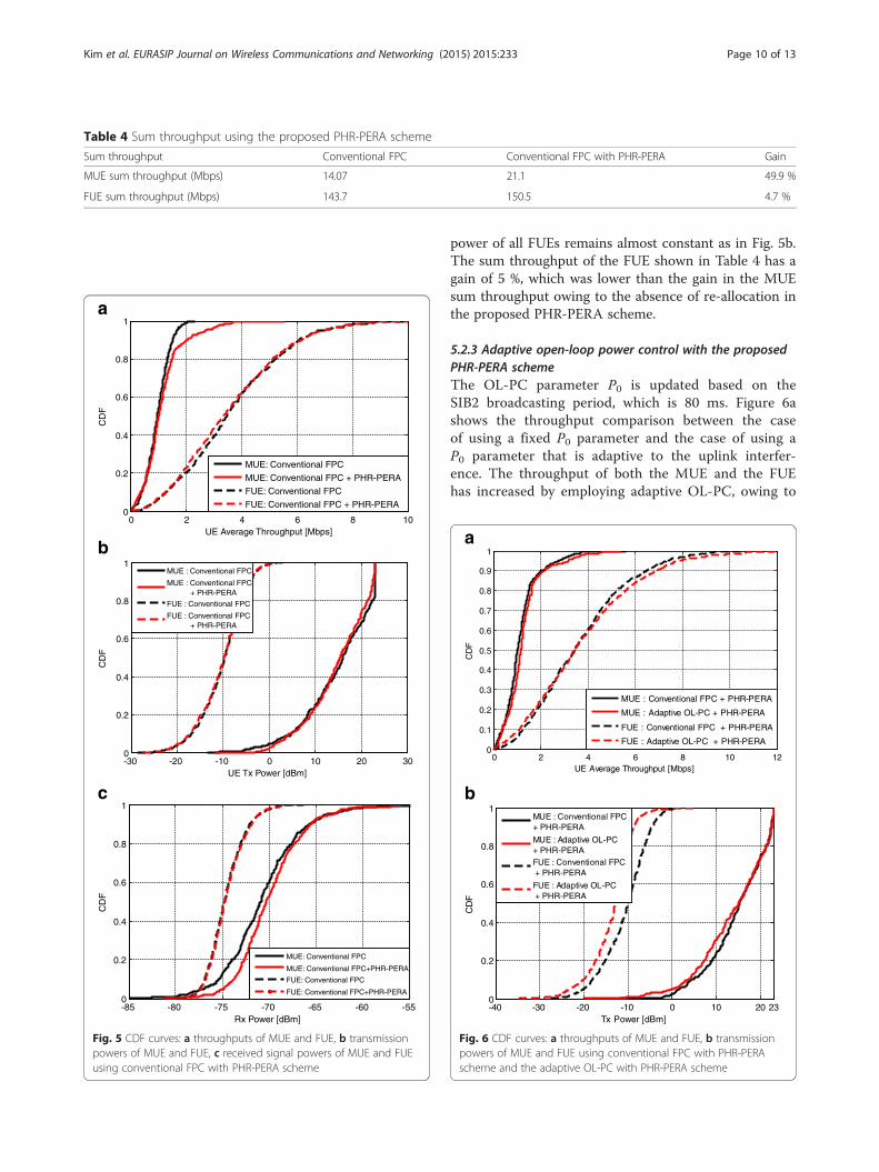
Table 4 Sum throughput using the proposed PHR-PERA scheme
Sum throughput Conventional FPC Conventional FPC with PHR-PERA Gain
MUE sum throughput (Mbps) 14.07 21.1 49.9 %
FUE sum throughput (Mbps) 143.7 150.5 4.7 %
0 2 4 6 8 100
0.2
0.4
0.6
0.8
1
UE Average Throughput [Mbps]
CD
F
MUE: Conventional FPC
MUE: Conventional FPC + PHR-PERA
FUE: Conventional FPC
FUE: Conventional FPC + PHR-PERA
-30 -20 -10 0 10 20 300
0.2
0.4
0.6
0.8
1
UE Tx Power [dBm]
CD
F
MUE : Conventional FPC
MUE : Conventional FPC + PHR-PERA
FUE : Conventional FPC
FUE : Conventional FPC + PHR-PERA
-85 -80 -75 -70 -65 -60 -550
0.2
0.4
0.6
0.8
1
Rx Power [dBm]
CD
F
MUE: Conventional FPC
MUE: Conventional FPC+PHR-PERA
FUE: Conventional FPC
FUE: Conventional FPC+PHR-PERA
b
c
Fig. 5 CDF curves: a throughputs of MUE and FUE, b transmissionpowers of MUE and FUE, c received signal powers of MUE and FUEusing conventional FPC with PHR-PERA scheme
Kim et al. EURASIP Journal on Wireless Communications and Networking (2015) 2015:233 Page 10 of 13
power of all FUEs remains almost constant as in Fig. 5b.The sum throughput of the FUE shown in Table 4 has again of 5 %, which was lower than the gain in the MUEsum throughput owing to the absence of re-allocation inthe proposed PHR-PERA scheme.
5.2.3 Adaptive open-loop power control with the proposedPHR-PERA schemeThe OL-PC parameter P0 is updated based on theSIB2 broadcasting period, which is 80 ms. Figure 6ashows the throughput comparison between the caseof using a fixed P0 parameter and the case of using aP0 parameter that is adaptive to the uplink interfer-ence. The throughput of both the MUE and the FUEhas increased by employing adaptive OL-PC, owing to
0 2 4 6 8 10 120
0.1
0.2
0.3
0.4
0.5
0.6
0.7
0.8
0.9
1
UE Average Throughput [Mbps]
CD
F
MUE : Conventional FPC + PHR-PERA
MUE : Adaptive OL-PC + PHR-PERA
FUE : Conventional FPC + PHR-PERA
FUE : Adaptive OL-PC + PHR-PERA
-40 -30 -20 -10 0 10 20 230
0.2
0.4
0.6
0.8
1
Tx Power [dBm]
CD
F
MUE : Conventional FPC+ PHR-PERA
MUE : Adaptive OL-PC+ PHR-PERAFUE : Conventional FPC + PHR-PERA
FUE : Adaptive OL-PC + PHR-PERA
b
Fig. 6 CDF curves: a throughputs of MUE and FUE, b transmissionpowers of MUE and FUE using conventional FPC with PHR-PERAscheme and the adaptive OL-PC with PHR-PERA scheme

Table 5 Sum throughput using adaptive OL-PC
Sum throughput Conventional FPC with PHR-PERA Adaptive OL-PC with PHR-PERA Gain
MUE sum throughput (Mbps) 21.1 24.74 21.9 %
FUE sum throughput (Mbps) 150.5 157.8 4.8 %
Kim et al. EURASIP Journal on Wireless Communications and Networking (2015) 2015:233 Page 11 of 13
the optimal value of P0 by considering the dynamicvariation of the received SINR and interference. InFig. 6b, it is seen that the transmission power of boththe MUE and the FUE has decreased, which causesless inter-cell interference with the neighboring cells,leading to improvement in the throughput. Therefore,
Fig. 7 Color map: a throughputs using conventional FPC, b throughputs u
by using adaptive OL-PC, more throughput can beachieved while using less UE transmission power.According to Table 5, the sum throughput of theMUE and FUE has the gain of 21.9 and 4.8 %, re-spectively, compared to the case of OL-PC with fixedP0. Figure 7a, b shows the throughput color maps for
sing adaptive OL-PC with the proposed PHR-PERA
-30 -20 -10 0 10 20 30 400
0.1
0.2
0.3
0.4
0.5
0.6
0.7
0.8
0.9
1
SINR [dB]
CD
F
SINR Target
OL-PC only
OL-PC + CL-PC
Fig. 8 SINRs of MUE and FUE
Kim et al. EURASIP Journal on Wireless Communications and Networking (2015) 2015:233 Page 12 of 13
the conventional and proposed schemes, respectively.The gain of adaptive OL-PC with the PHR-PERAscheme can be clearly seen by the darker red color,which indicates higher throughput in Fig. 7b com-pared to Fig. 7a.
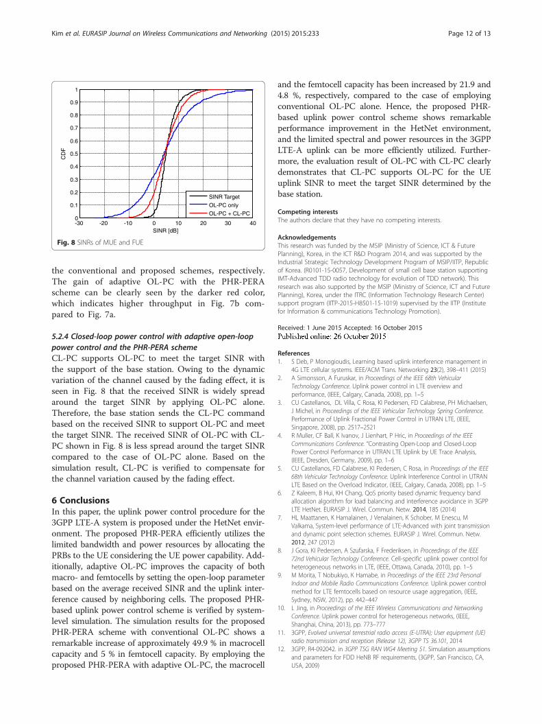
5.2.4 Closed-loop power control with adaptive open-looppower control and the PHR-PERA schemeCL-PC supports OL-PC to meet the target SINR withthe support of the base station. Owing to the dynamicvariation of the channel caused by the fading effect, it isseen in Fig. 8 that the received SINR is widely spreadaround the target SINR by applying OL-PC alone.Therefore, the base station sends the CL-PC commandbased on the received SINR to support OL-PC and meetthe target SINR. The received SINR of OL-PC with CL-PC shown in Fig. 8 is less spread around the target SINRcompared to the case of OL-PC alone. Based on thesimulation result, CL-PC is verified to compensate forthe channel variation caused by the fading effect.
6 ConclusionsIn this paper, the uplink power control procedure for the3GPP LTE-A system is proposed under the HetNet envir-onment. The proposed PHR-PERA efficiently utilizes thelimited bandwidth and power resources by allocating thePRBs to the UE considering the UE power capability. Add-itionally, adaptive OL-PC improves the capacity of bothmacro- and femtocells by setting the open-loop parameterbased on the average received SINR and the uplink inter-ference caused by neighboring cells. The proposed PHR-based uplink power control scheme is verified by system-level simulation. The simulation results for the proposedPHR-PERA scheme with conventional OL-PC shows aremarkable increase of approximately 49.9 % in macrocellcapacity and 5 % in femtocell capacity. By employing theproposed PHR-PERA with adaptive OL-PC, the macrocell
and the femtocell capacity has been increased by 21.9 and4.8 %, respectively, compared to the case of employingconventional OL-PC alone. Hence, the proposed PHR-based uplink power control scheme shows remarkableperformance improvement in the HetNet environment,and the limited spectral and power resources in the 3GPPLTE-A uplink can be more efficiently utilized. Further-more, the evaluation result of OL-PC with CL-PC clearlydemonstrates that CL-PC supports OL-PC for the UEuplink SINR to meet the target SINR determined by thebase station.
Competing interestsThe authors declare that they have no competing interests.
AcknowledgementsThis research was funded by the MSIP (Ministry of Science, ICT & FuturePlanning), Korea, in the ICT R&D Program 2014, and was supported by theIndustrial Strategic Technology Development Program of MSIP/IITP, Republicof Korea. (R0101-15-0057, Development of small cell base station supportingIMT-Advanced TDD radio technology for evolution of TDD network). Thisresearch was also supported by the MSIP (Ministry of Science, ICT and FuturePlanning), Korea, under the ITRC (Information Technology Research Center)support program (IITP-2015-H8501-15-1019) supervised by the IITP (Institutefor Information & communications Technology Promotion).
Received: 1 June 2015 Accepted: 16 October 2015
References1. S Deb, P Monogioudis, Learning based uplink interference management in
4G LTE cellular systems. IEEE/ACM Trans. Networking 23(2), 398–411 (2015)2. A Simonsson, A Furuskar, in Proceedings of the IEEE 68th Vehicular
Technology Conference. Uplink power control in LTE overview andperformance, (IEEE, Calgary, Canada, 2008), pp. 1–5
3. CU Castellanos, DL Villa, C Rosa, KI Pedersen, FD Calabrese, PH Michaelsen,J Michel, in Proceedings of the IEEE Vehicular Technology Spring Conference.Performance of Uplink Fractional Power Control in UTRAN LTE, (IEEE,Singapore, 2008), pp. 2517–2521
4. R Muller, CF Ball, K Ivanov, J Lienhart, P Hric, in Proceedings of the IEEECommunications Conference. “Contrasting Open-Loop and Closed-LoopPower Control Performance in UTRAN LTE Uplink by UE Trace Analysis,(IEEE, Dresden, Germany, 2009), pp. 1–6
5. CU Castellanos, FD Calabrese, KI Pedersen, C Rosa, in Proceedings of the IEEE68th Vehicular Technology Conference. Uplink Interference Control in UTRANLTE Based on the Overload Indicator, (IEEE, Calgary, Canada, 2008), pp. 1–5
6. Z Kaleem, B Hui, KH Chang, QoS priority based dynamic frequency bandallocation algorithm for load balancing and interference avoidance in 3GPPLTE HetNet. EURASIP J. Wirel. Commun. Netw. 2014, 185 (2014)
7. HL Maattanen, K Hamalainen, J Venalainen, K Schober, M Enescu, MValkama, System-level performance of LTE-Advanced with joint transmissionand dynamic point selection schemes. EURASIP J. Wirel. Commun. Netw.2012, 247 (2012)
8. J Gora, KI Pedersen, A Szufarska, F Frederiksen, in Proceedings of the IEEE72nd Vehicular Technology Conference. Cell-specific uplink power control forheterogeneous networks in LTE, (IEEE, Ottawa, Canada, 2010), pp. 1–5
9. M Morita, T Nobukiyo, K Hamabe, in Proceedings of the IEEE 23rd PersonalIndoor and Mobile Radio Communications Conference. Uplink power controlmethod for LTE femtocells based on resource usage aggregation, (IEEE,Sydney, NSW, 2012), pp. 442–447
10. L Jing, in Proceedings of the IEEE Wireless Communications and NetworkingConference. Uplink power control for heterogeneous networks, (IEEE,Shanghai, China, 2013), pp. 773–777
11. 3GPP, Evolved universal terrestrial radio access (E-UTRA); User equipment (UE)radio transmission and reception (Release 12), 3GPP TS 36.101, 2014
12. 3GPP, R4-092042. in 3GPP TSG RAN WG4 Meeting 51. Simulation assumptionsand parameters for FDD HeNB RF requirements, (3GPP, San Francisco, CA,USA, 2009)

Kim et al. EURASIP Journal on Wireless Communications and Networking (2015) 2015:233 Page 13 of 13
13. 3GPP, Evolved universal terrestrial radio access (E-UTRA); Radio Frequency (RF)system scenarios (Release 8), 3GPP TR 36.942, 2012
14. I Ahmad, Z Kaleem, KH Chang, QoS priority based femtocell user powercontrol for interference mitigation in 3GPP LTE-A HetNet. J. Korean Inf.Commun. Soc. 39A(02), 61–74 (2014)
15. 3GPP, Evolved universal terrestrial radio access (E-UTRA); Physical layerprocedures, 3GPP TS 36.213, 2014
16. 3GPP, Evolved Universal Terrestrial Radio Access (E-UTRA); Radio ResourceControl (RRC); Protocol specification, 3GPP TS 36.331, 2013
17. F Bendaoud, M Abdennebi, F Didi, Survey on scheduling and radioresources allocation in LTE. Int. J. Next-Generation Netw. 6(1), 17–29 (2014)
18. 3GPP, R1-074266. in 3GPP TSG RAN WG1 Meeting 50. UL power controlparameter values in PUSCH power control, (Shanghai, China, 2007)
19. M Wrulich, JC Ikuno, D Bosanska, M Rupp, in Proceedings of the EuropeanSignal Processing Conference (EUSIPCO). Simulating the long term evolutionphysical layer, (EURASIP, Glasgow, Scotland, 2009), pp. 1472–1478
20. E Tejaswi, B Suresh, Survey of power control schemes for LTE uplink. Int. J.Comput. Sci. Inf. Technol. 4(2), 369–373 (2013)
21. 3GPP, Evolved Universal Terrestrial Radio Access (E-UTRA); Furtheradvancements for E-UTRA physical layer aspects, 3GPP TS 36.814, 2010
Submit your manuscript to a journal and benefi t from:
7 Convenient online submission
7 Rigorous peer review
7 Immediate publication on acceptance
7 Open access: articles freely available online
7 High visibility within the fi eld
7 Retaining the copyright to your article
Submit your next manuscript at 7 springeropen.com