Power Generation division - Polyimpex · Cummins KTA 50-G3 1000 1250 255 20 Ft. - ISO container INT...
20
Power Generation division
Transcript of Power Generation division - Polyimpex · Cummins KTA 50-G3 1000 1250 255 20 Ft. - ISO container INT...

Power Generation division
1. INTERTECH
1. Products with MAN engines (Germany) (gas reciprocating contain er-based units, 200 to 1,600 kW)
2. Products with MTU engines (Germany) (gas-reciprocating container-based or sound enclosure-based units, 1 to 4 MW)
3. Products with MTU and Cummins engines (Germany) (diesel container-based units)
4. Products with ABC engines (Belgium) (dual-fuel container-based units)
2. OPRA GAS TURBINE UNITS, 1,850 kW electricity
3. Turboden ORC (Organic Rankine Cycle) turbogenerators.
CATALOG CONTENTS
INTRODUCTION
CHP units are suitable for comprehensive stand-alone power supply solutions.
A CHP unit is a power station which co-generates electric power and heat.
A CHP unit includes a gas-reciprocating engine, a generator, closed-loop heat exchangers, pumps, safety features, and power equipment control, moni-toring, and planning systems.
An internal combustion engine drives the generator producing electricity. The resulting current is supplied directly to the internal or external grid, or to a switchboard wired to separate consumers.
The heat recovered from the engine's cooling jacket, as well as the exhaust gas heat is transferred through the heat exchangers and pumps to the heat carrier for supplying hot water and heating the building. On average, for each 100 kW of electricity, the user obtains 120 kW of thermal power as hot water (+90 0С to +95 0С).
CHP Unit Benefits:
• an important mini CHP unit's benefit is lower operating costs for heat and power generation and transportation.
• engines fully utilize the fuel; efficiency exceeds 90 %;
• the efficiency of a a gas-reciprocating engine remains virtually unchanged with load variations;
• the units are environment-friendly;
• the price per 1 kW generated by such a unit is about one half to one third of the price offered by centralized power generation and distribution facilities;
• concurrent operation of a CHP unit and common heating networks guarantees trouble-free, or emergency power supply;
• independence from monopolistic power suppliers while ensuring heat supply;
• short payback period;
• CHP units are located next to the users;
• excellent reliability enabled by first-class equipment from the world's leading manufacturers;
• an automated control system with remote planning functions;
• container-based design: no structures need to be erected;
• the electrical efficiency of a gas-piston engine exceeds that of a gas turbine.
This becomes all the more significant when electricity is the primary kind of energy generated.
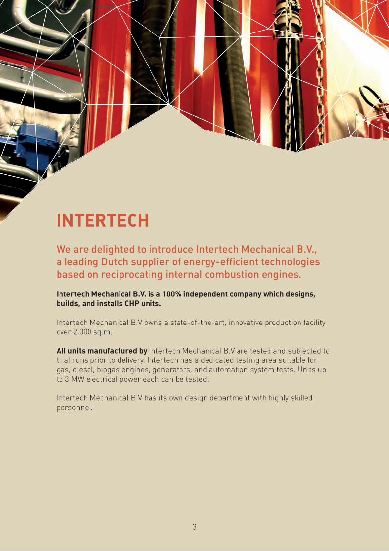
INTERTECH
We are delighted to introduce Intertech Mechanical B.V., a leading Dutch supplier of energy-efficient technologies based on reciprocating internal combustion engines.
Intertech Mechanical B.V. is a 100% independent company which designs, builds, and installs CHP units.
Intertech Mechanical B.V owns a state-of-the-art, innovative production facility over 2,000 sq.m.
All units manufactured by Intertech Mechanical B.V are tested and subjected to trial runs prior to delivery. Intertech has a dedicated testing area suitable for gas, diesel, biogas engines, generators, and automation system tests. Units up to 3 MW electrical power each can be tested.
Intertech Mechanical B.V has its own design department with highly skilled personnel.
3

INTERTECH Container-based, MAN Engine-Powered Product Line:
One CHP unit in a standard 20 ft. container
Module type Int-50 Int-70 Int-115 Int-140 Int-200 Int-240 Int-400
Electrical capacity, kW 50 70 113 140 201 237 402
Heat output, kW 82 114 180 216 333 372 538
Fuel Natural gas
Fuel consumption, kW 146 204 328 392 596 669 1045
Electrical efficiency, % 34,2 34,3 34,5 35,7 35,7 37,4 39,5
Thermal efficiency, % 56,2 55,9 54,9 55,1 55,9 55,6 51,5
Total efficiency, % 90,4 90,2 89,4 90,8 89,6 91 90
Dimensions:
- length, mm 2600 2600 3200 3200 3200 3200 3600
- width, mm 900 900 1200 1200 1400 1400 1400
- height, mm 1850 1850 2100 2100 2100 2100 2200
Service weight 1900 2000 2800 2850 4600 4600 5875
Noise level, dB(A) distance 1 m 62 63 66 66 70 70 72
Container 20 Ft 20 Ft 20 Ft 20 Ft 20 Ft 20 Ft 20 Ft
4
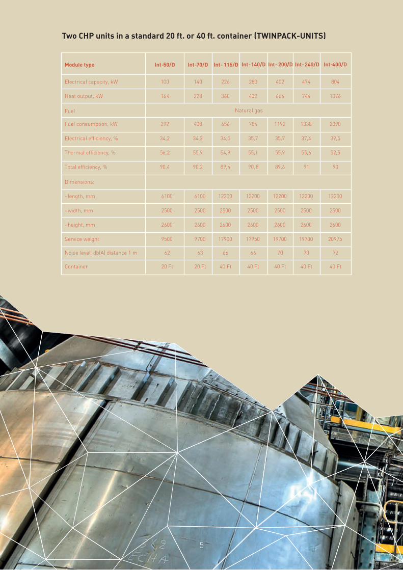
Two CHP units in a standard 20 ft. or 40 ft. container (TWINPACK-UNITS)
Module type Int-50/D Int-70/D
Int- 115/D Int-140/D Int- 200/D Int-240/D Int-400/D
Electrical capacity, kW 100 140 226 280 402 474 804
Heat output, kW 164 228 360 432 666 744 1076
Fuel Natural gas
Fuel consumption, kW 292 408 656 784 1192 1338 2090
Electrical efficiency, % 34,2 34,3 34,5 35,7 35,7 37,4 39,5
Thermal efficiency, % 56,2 55,9 54,9 55,1 55,9 55,6 52,5
Total efficiency, % 90,4 90,2 89,4 90,8 89,6 91 90
Dimensions:
- length, mm 6100 6100 12200 12200 12200 12200 12200
- width, mm 2500 2500 2500 2500 2500 2500 2500
- height, mm 2600 2600 2600 2600 2600 2600 2600
Service weight 9500 9700 17900 17950 19700 19700 20975
Noise level, db(A) distance 1 m 62 63 66 66 70 70 72
Container 20 Ft 20 Ft 40 Ft 40 Ft 40 Ft 40 Ft 40 Ft
5
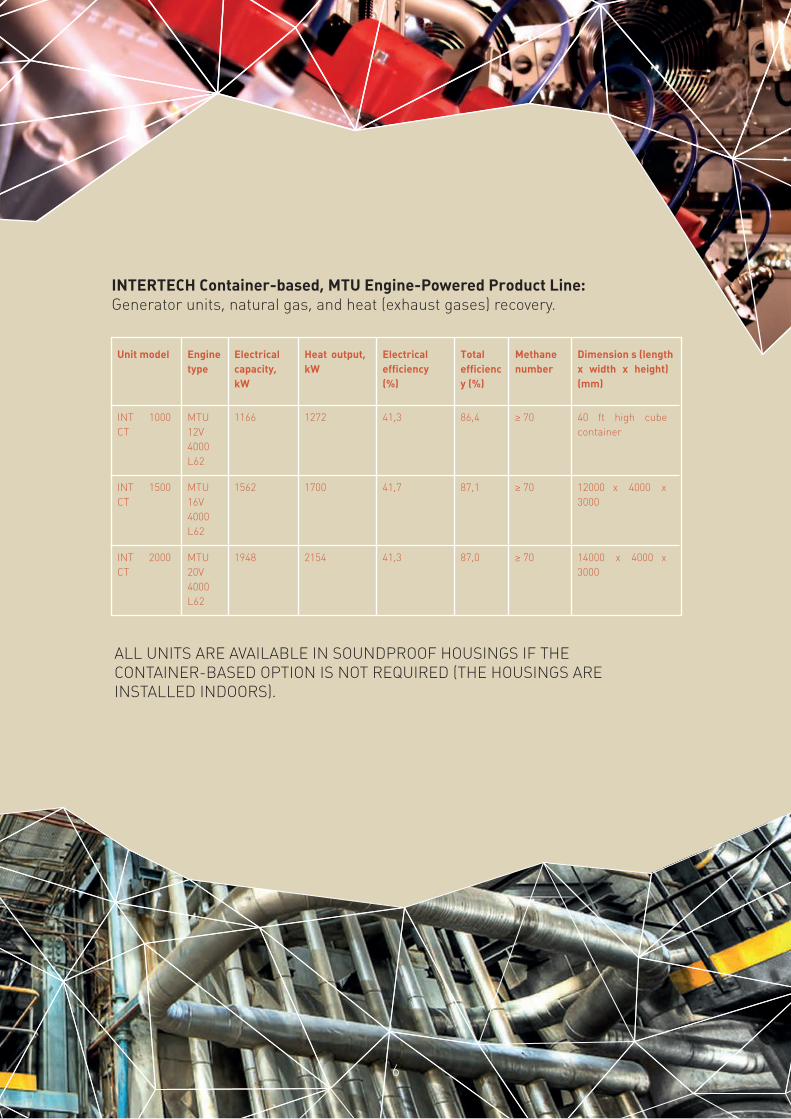
ALL UNITS ARE AVAILABLE IN SOUNDPROOF HOUSINGS IF THE CONTAINER-BASED OPTION IS NOT REQUIRED (THE HOUSINGS ARE INSTALLED INDOORS).
INTERTECH Container-based, MTU Engine-Powered Product Line:Generator units, natural gas, and heat (exhaust gases) recovery.
Unit model Engine type
Electrical capacity, kW
Heat output, kW
Electrical efficiency (%)
Total efficiency (%)
Methane number
Dimension s (length х width х height) (mm)
INT 1000 CT
MTU 12V 4000 L62
1166 1272 41,3 86,4 ≥ 70 40 ft high cube container
INT 1500 CT
MTU 16V 4000 L62
1562 1700 41,7 87,1 ≥ 70 12000 x 4000 x 3000
INT 2000 CT
MTU 20V 4000 L62
1948 2154 41,3 87,0 ≥ 70 14000 x 4000 x3000
6
7
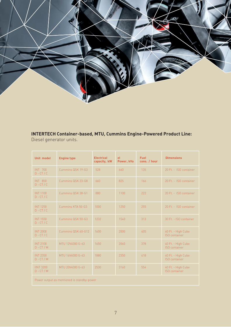
INTERTECH Container-based, MTU, Cummins Engine-Powered Product Line:Diesel generator units.
Unit model Engine type Electrical capacity, kW
el Power , kVa
Fuel cons. / hour
Dimensions
INT 700 D - CT / C
Cummins QSK 19-G3 528
660
135
20 Ft. - ISO container
INT 850 D - CT / C
Cummins QSK 23-G8 660 825 166 20 Ft. - ISO container
INT 1100 D - CT / C
Cummins QSK 38-G1 880 1100 222 20 Ft. - ISO container
INT 1250 D - CT / C
Cummins KTA 50-G3 1000 1250 255 20 Ft. - ISO container
INT 1550 D - CT / C
Cummins QSK 50-G3 1232 1540 313 30 Ft. - ISO container
INT 2000 D - CT / C
Cummins QSK 60-G12 1600 2000 405 40 Ft. - High Cube ISO container
INT 2100 D - CT / M
MTU 12V4000 G-63 1650 2060 378 40 Ft. - High Cube ISO container
INT 2350 D - CT / M
MTU 16V4000 G-63 1880 2350 418 40 Ft. - High CubeISO container
IINT 3200 D - CT / M
MTU 20V4000 G-63 2530 3160 554 40 Ft. - High Cube ISO container
Power output as mentioned is standby-power
8
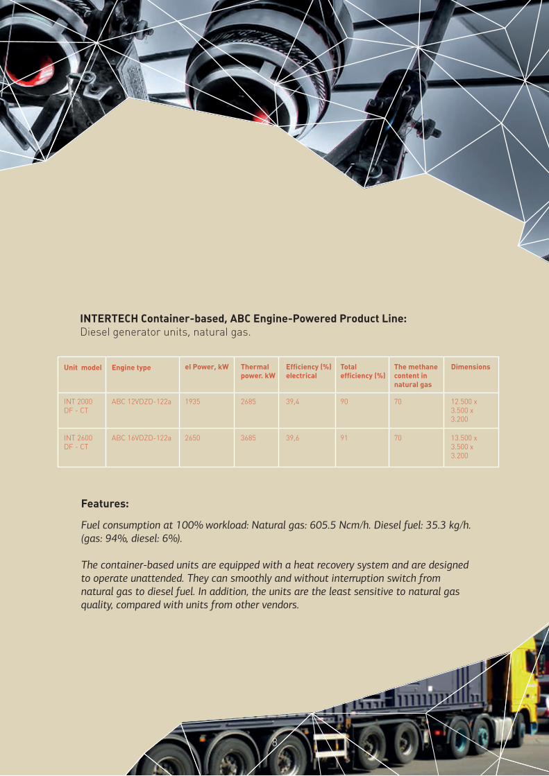
Features:
Fuel consumption at 100% workload: Natural gas: 605.5 Ncm/h. Diesel fuel: 35.3 kg/h. (gas: 94%, diesel: 6%).
The container-based units are equipped with a heat recovery system and are designed to operate unattended. They can smoothly and without interruption switch from natural gas to diesel fuel. In addition, the units are the least sensitive to natural gas quality, compared with units from other vendors.
INTERTECH Container-based, ABC Engine-Powered Product Line:Diesel generator units, natural gas.
Unit model Engine type el Power, kW Thermal power. kW
Efficiency (%) electrical
Total efficiency (%)
The methane content in natural gas
Dimensions
INT 2000 DF - CT
ABC 12VDZD-122a 1935
2685
39,4
90 70
INT 2600 DF - CT
ABC 16VDZD-122a 2650 3685 39,6 91 70
12.500 x 3.500 x 3.200
13.500 x 3.500 x 3.200
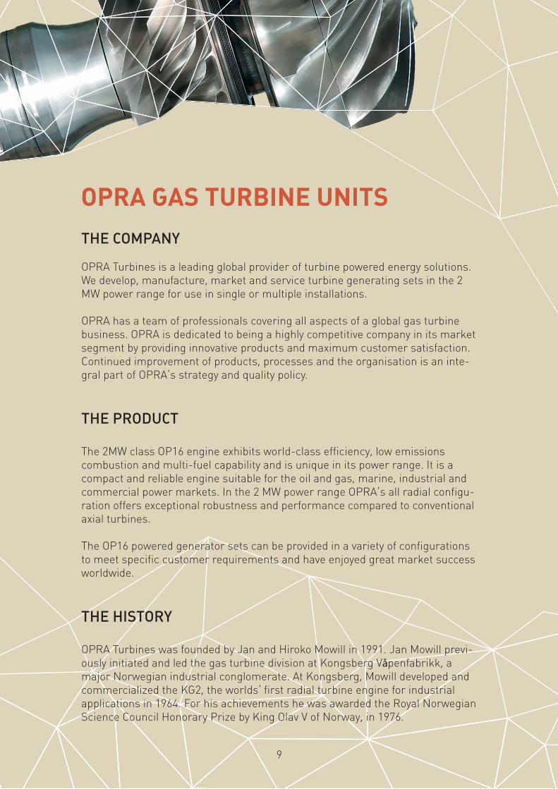
OPRA GAS TURBINE UNITS
THE COMPANY
OPRA Turbines is a leading global provider of turbine powered energy solutions. We develop, manufacture, market and service turbine generating sets in the 2 MW power range for use in single or multiple installations.
OPRA has a team of professionals covering all aspects of a global gas turbine business. OPRA is dedicated to being a highly competitive company in its market segment by providing innovative products and maximum customer satisfaction. Continued improvement of products, processes and the organisation is an inte-gral part of OPRA’s strategy and quality policy.
THE PRODUCT
The 2MW class OP16 engine exhibits world-class efficiency, low emissions combustion and multi-fuel capability and is unique in its power range. It is a compact and reliable engine suitable for the oil and gas, marine, industrial and commercial power markets. In the 2 MW power range OPRA’s all radial configu-ration offers exceptional robustness and performance compared to conventional axial turbines.
The OP16 powered generator sets can be provided in a variety of configurations to meet specific customer requirements and have enjoyed great market success worldwide.
THE HISTORY
OPRA Turbines was founded by Jan and Hiroko Mowill in 1991. Jan Mowill previ-ously initiated and led the gas turbine division at Kongsberg Våpenfabrikk, a major Norwegian industrial conglomerate. At Kongsberg, Mowill developed and commercialized the KG2, the worlds’ first radial turbine engine for industrial applications in 1964. For his achievements he was awarded the Royal Norwegian Science Council Honorary Prize by King Olav V of Norway, in 1976.
9
10
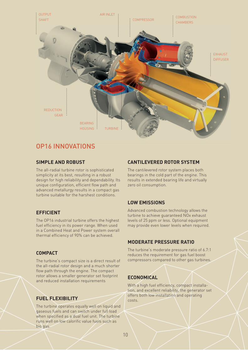
OP16 INNOVATIONS
OUTPUT
SHAFT
AIR INLET
COMPRESSORCOMBUSTION
CHAMBERS
EXHAUST
DIFFUSER
TURBINE
BEARING
HOUSING
REDUCTION
GEAR
SIMPLE AND ROBUST
The all-radial turbine rotor is sophisticated simplicity at its best, resulting in a robust design for high reliability and dependability. Its unique configuration, efficient flow path and advanced metallurgy results in a compact gas turbine suitable for the harshest conditions.
EFFICIENT
The OP16 industrial turbine offers the highest fuel efficiency in its power range. When used in a Combined Heat and Power system overall thermal efficiency of 90% can be achieved.
COMPACT
The turbine’s compact size is a direct result of the all-radial rotor design and a much shorter flow path through the engine. The compact rotor allows a smaller generator set footprint and reduced installation requirements
FUEL FLEXIBILITY
The turbine operates equally well on liquid and gaseous fuels and can switch under full load when specified as a dual fuel unit. The turbine runs well on low calorific value fuels such as bio gas.
CANTILEVERED ROTOR SYSTEM
The cantilevered rotor system places both bearings in the cold part of the engine. This results in extended bearing life and virtually zero oil consumption.
LOW EMISSIONS
Advanced combustion technology allows the turbine to achieve guaranteed NOx exhaust levels of 25 ppm or less. Optional equipment may provide even lower levels when required.
MODERATE PRESSURE RATIO
The turbine’s moderate pressure ratio of 6.7:1 reduces the requirement for gas fuel boost compressors compared to other gas turbines.
ECONOMICAL
With a high fuel efficiency, compact installa-tion, and excellent reliability, the generator set offers both low installation and operating costs.

PACKAGE SPECIFICATIONS
GENERATOR
• Synchronous 4-pole, 3 phase
• Open drip proof construction
• Integral brushless exciter
• 2250 kVA, 50/60 Hz, 400/480V
• Acceleration vibration transducer
• Integrated solid state AVR
• H-class insulation,
• H-class temperature rise
OPTIONAL EQUIPMENT
• Generator options
• Alternative voltages
• Standby ratings
• Fuel systems
• Dual fuel system
• Bi fuel system
• Dry Low Emission system
• Alternative fuels like biogas, synthetic gas, etc.
• Oil System Options
• Oil demister
• Duplex oil filter
• Weatherproof acoustic enclosure (85 dBa 1m)
• F&G detection system
• Fire extinguishing system
• Engine intake filtration
• Package ventilation
• Silencers and ducting
• Anti-icing
• Fully pre-wired on-skid control room
• Exhaust or WHR options
FRONT VIEW
REAR VIEW
1980 mm
1850
mm
11

12
SIDE VIEW
5400 mm
OP 16 GAS TURBINE
• Single shaft
• Single stage centrifugal compressor
• Single stage radial turbine
• 4 can combustion system
• Dual fuel and DLE combustion system
• High energy spark ignition system
GEAR REDUCTION
• Integral epicyclical gear
• 1500 or 1800 rpm
• Acceleration vibration transducer
• Ancillary drive shafts
• Shear pin drive shaft protection
STANDARD GENERATOR PACKAGE
• Steel base frame
• Hydroelectric starting system
• Natural gas fuel system
• Lubrication oil system
• Gear driven main oil pump
• AC pre/post lube oil pump
• Air - oil cooler
• Integrated lube oil tank
• Lube oil tank heater
• Simplex oil filter
• Unit control system
• Microprocessor based PLC
• Package sequencing and turbine governing
• Generator auto synchroniz ing and protection
• Vibration Monitoring
• 24 VDC Batteries and charging system
• Online water wash systemand gaseous fuels and can
switch under full load when specified as a dual fuel unit. The turbine runs well on low calorific value fuels such as bio gas.
13
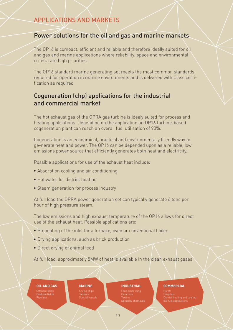
APPLICATIONS AND MARKETS
Power solutions for the oil and gas and marine markets
The OP16 is compact, efficient and reliable and therefore ideally suited for oil and gas and marine applications where reliability, space and environmental criteria are high priorities.
The OP16 standard marine generating set meets the most common standards required for operation in marine environments and is delivered with Class certi-fication as required
Cogeneration (chp) applications for the industrial and commercial market
The hot exhaust gas of the OPRA gas turbine is idealy suited for process and heating applications. Depending on the application an OP16 turbine-based cogeneration plant can reach an overall fuel utilisation of 90%.
Cogeneration is an economical, practical and environmentally friendly way to ge-nerate heat and power. The OP16 can be depended upon as a reliable, low emissions power source that efficiently generates both heat and electricity.
Possible applications for use of the exhaust heat include:
• Absorption cooling and air conditioning
• Hot water for district heating
• Steam generation for process industry
At full load the OPRA power generation set can typically generate 6 tons per hour of high pressure steam.
The low emissions and high exhaust temperature of the OP16 allows for direct use of the exhaust heat. Possible applications are:
• Preheating of the inlet for a furnace, oven or conventional boiler
• Drying applications, such as brick production
• Direct drying of animal feed
At full load, approximately 5MW of heat is available in the clean exhaust gases.
OIL AND GAS Offshore fields Onshore fields Pipelines
MARINECruise ships Tankers Special vessels
INDUSTRIAL Food processing Ceramics Textiles Specialty chemicals
COMMERCIAL Hotels Hospitals District heating and cooling Bio fuel applications

TURBODEN ORC (ORGANIC RANKINE CYCLE) TURBOGENERATORS
THE COMPANY
Turboden is a leading European company in development and production of ORC (Organic Rankine Cycle) turbogenerators. This state of the art equipment gener-ates heat and power from renewable sources and heat recovery in industrial processes.
The company was founded in 1980 in Milan by Mario Gaia, former Professor of Energy at the university Politecnico di Milano, and today the Managing Director of Turboden. His close connection with the university has always ensured the recruitment of highly qualified R&D personnel.
Turboden has always had a single mission: design ORC turbogenerators for the production of heat and electrical power from renewable sources, while constant-ly striving to implement ORC technical solutions.
In 2009, Turboden became part of Pratt & Whitney (UTC Corp.), a worldwide leader in development, production and service for aero engines, aerospace drive systems and heavy duty gas turbines.
Today Turboden is part of Pratt & Whitney Power Systems (PWPS), to develop ORC solutions from renewable sources and waste heat worldwide.
14

15
WHAT WE DO
Turboden designs and develops turbogenerators based on the Organic Rankine Cycle (ORC), a technology for the combined generation of heat and electrical power from various renewable sources, particularly suitable for distributed generation.
HEAT
ELECTRICITY
STANDARD UNITS FROM 600 KW TO 6 MW
CUSTOMIZED SOLUTIONS UP TO 15 MW
BIOMASS GEOTHERMAL SOLAR WASTE-HEAT

THE THERMODYNAMIC PRINCIPLE: THE ORC CYCLE
The turbogenerator uses the hot temperature thermal oil to pre-heat and vapor-ize a suitable organic working fluid in the evaporator (8 3 4).
The organic fluid vapor powers the turbine (4 5), which is directly coupled to the electric generator through an elastic coupling.
The exhaust vapor flows through the regenerator (5 9) where it heats the organic liquid (2 8).
The vapor is then condensed in the condenser (cooled by the water flow) (9 6 1).
The organic fluid liquid is finally pumped (1 2) to the regenerator and then to the evaporator, thus completing the sequence of operations in the closed-loop circuit.
16
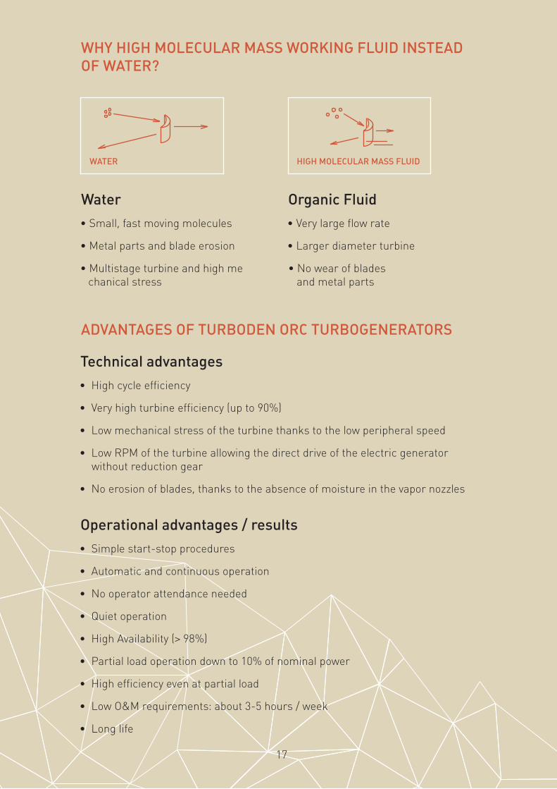
WHY HIGH MOLECULAR MASS WORKING FLUID INSTEAD OF WATER?
ADVANTAGES OF TURBODEN ORC TURBOGENERATORS
Water
• Small, fast moving molecules
• Metal parts and blade erosion
• Multistage turbine and high me chanical stress
Organic Fluid
• Very large flow rate
• Larger diameter turbine
• No wear of blades and metal parts
WATER HIGH MOLECULAR MASS FLUID
Technical advantages
• High cycle efficiency
• Very high turbine efficiency (up to 90%)
• Low mechanical stress of the turbine thanks to the low peripheral speed
• Low RPM of the turbine allowing the direct drive of the electric generator without reduction gear
• No erosion of blades, thanks to the absence of moisture in the vapor nozzles
Operational advantages / results
• Simple start-stop procedures
• Automatic and continuous operation
• No operator attendance needed
• Quiet operation
• High Availability (> 98%)
• Partial load operation down to 10% of nominal power
• High efficiency even at partial load
• Low O&M requirements: about 3-5 hours / week
• Long life
17

HR MODULES STANDARD SIZES AND TYPICAL PERFORMANCES
LAYOUT – SOME EXAMPLES
Heat Recovery
Turboden ORCs can produce electricity by recovering heat from industrial processes, reciprocating engines and gas turbines. The power of Turboden Turbogenerators in this application generally ranges between 600 kW and 10 MW electric.
BIOMASS GEOTHERMALSOLAR THERMALPOWER
HEAT RECOVERY
TURBODEN 7 layout TURBODEN 10 layout TURBODEN 18 layout
18

Polympex AG, Industriestrasse 7,P.O. Box, CH-6301 Zug
www.polyimpex.chtel: + 41 (0) 41 725 05 90fax: + 41 (0) 41 725 05 91mail: [email protected]