Power electronics - Universiteit Gent
80
3 / 2008 The corporate technical journal of the ABB Group www.abb.com/abbreview ABB Review Pioneering spirits A revolution in high dc current measurement page 6 Team-mates: MultiMove functionality heralds a new era in robot applications page 26 Best innovations 2004 page 43 a Power electronics IGBT: a tiny chip with a huge impact page 19 Drives: more performance using less energy page 30 Wind converters: making electricity from air page 56
Transcript of Power electronics - Universiteit Gent
3 / 2008
The corporate technical journal of the ABB Group
www.abb.com/abbreview
ABBReview
Pioneering spirits
A revolution in high dc current measurement
page 6
Team-mates: MultiMove functionality heralds a new era in robot applications
page 26
Best innovations 2004page 43
a
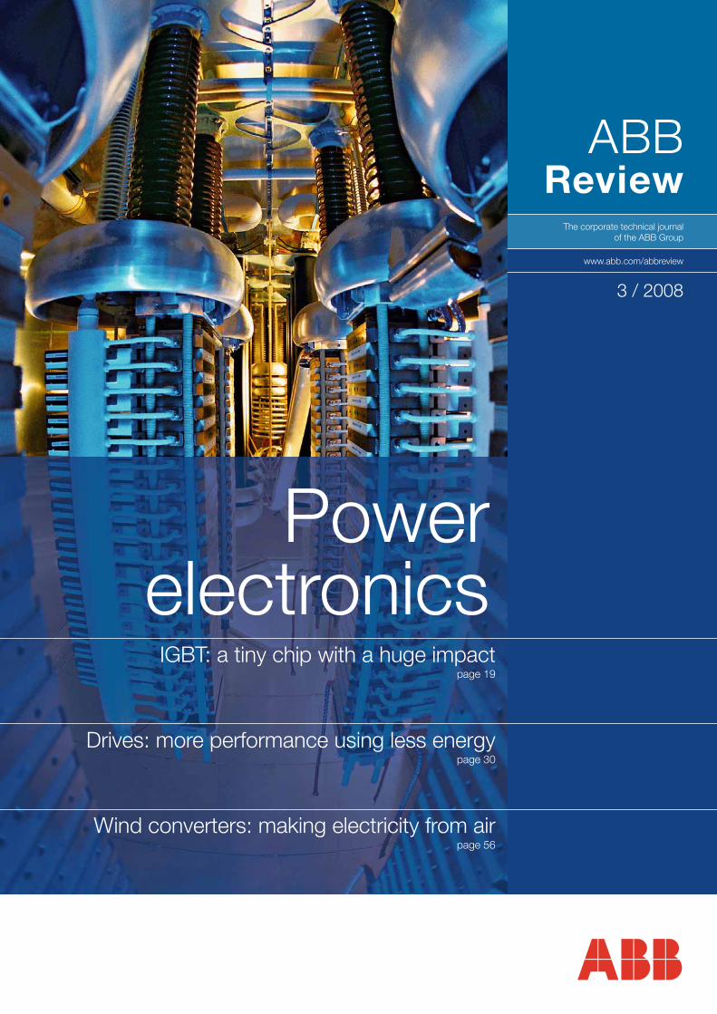
Powerelectronics
IGBT: a tiny chip with a huge impact page 19
Drives: more performance using less energypage 30
Wind converters: making electricity from air page 56

The power electronics revolution, which has over the past decadeswept across the power and auto-mation sectors, has opened up unprecedented possibilities in terms of controlling the way electrical energy is transported and used.
Electrical energy can now be trans-mitted more efficiently (the cover illustration shows the IGBT-powered valves of an HVDC Light® conver-ter). Variable-speed drives permit motors to be controlled in ways that previously were not thought possi-ble, while at the same time drasti-cally reducing the energy bills of the industries that use them.
3ABB Review 3/2008
Editorial
We have grown used to the thought that millions of transis-tors enable the performance of our laptops and consumer electronics. But would you have believed that someday our electrical power would flow through billions of transistors?
Whereas early rectifier and inverter stations had a handful of diodes or thyristors, a modern HVDC Light® station may have 100 billion transistors, when the number of IGBT modules, the chips within those modules and the micro-structures on those chips are considered. The sheer scale of integration required leads to high demands on reliabili-ty, requirements that ABB’s advanced design and manufac-turing teams are well-equipped to meet.
When ABB developed its first silicon diode with 100 A and 600 V in the early 1960s, nobody in their wildest dreams could imagine that such complexity, sophistication and fine-tuned functionality could ever be reached. Nor could anyone predict that electrical current, en route from the power plant to the end customer, would flow through con-trolled silicon junctions, managing several hundred MW of power today, 10,000 times that just half a century ago.
No wonder power semiconductors have taken the leading role in almost all electrical applications: Drives to efficient-ly operate motors are available from 10 W to several hun-dred MW. Electrical energy up to 6 GW can now be trans-mitted through HVDC lines at almost 1,000 kV. Trains, ele-vators and cranes run smoothly with power electronics. The connection of renewable energy sources, such as wind turbines, to the electric grid is enabled by converters. Even
radar systems depend on power semiconductors to secure-ly operate air traffic.
In all these achievements, ABB has played a leading role. ABB Review is proud to present a collection of applica-tions, as well as the technology itself, that makes all this possible. Not only does the technology add comfort and productivity when applied, it also helps to save energy. ABB’s product and system portfolio, aimed at increasing energy efficiency, is very broad and almost all offerings depend on the use of power semiconductors.
As individuals, we see the enormous progress of electronic components in our computers, digital media players, digital cameras, etc. A similar but much less visible evolution has also occurred in electrical power – but this is one that we easily take for granted, not recognizing most of the huge progress. This edition of ABB Review will take you behind the scenes, revealing the infrastructure that has become a natural part of our lives.
Enjoy your reading.
Peter TerwieschChief Technology OfficerABB Ltd.
The unseen evolution
4 ABB Review 3/2008
ABB Review 3/2008Power electronics
Contents
Semiconductors
6Conducting businessOne powerhouse is making the core of ABB’s power
electronics products: the semiconductor plant in
Lenzburg.
9Performance-enhancing packagingIGBT module packaging is about thinking outside the
box.
15A tiny dot can change the worldThe IGCT is a superlative under semiconductors in terms
of power ratings and switching.
19Switching to higher performanceMeet the silicon chip that took more than a chip out of
the market, and switched the way we think about power
electronics: the IGBT.
Drives
25The workhorse and its jockeyFind out how ABB’s drives are keeping many an
industrial workhorse ahead in the race for efficiency and
productivity.
30A team of drivesThe cement industry benefits as several drives team up.
Converters
35The compact controllerAn exciting development – the PP D104 controller – is
just the ticket for traction and excitation applications.
40AC excitation with ANPCA new switching topology is enabling a higher level of
excitation in pump storage plants.
44Clean and invisibleRenewable energies spark a reassessment of old
operating methods in grids.
49The railway connectionABB frequency converters empower railway grids.
56Offshore but onlineABB technology helps society face the wind of change.
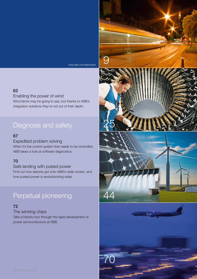
ABB Review 3/2008
9
25
44
70
62Enabling the power of windWind farms may be going to sea, but thanks to ABB’s
integration solutions they’re not out of their depth.
Diagnosis and safety
67Expedited problem solvingWhen it’s the control system that needs to be controlled,
ABB takes a look at software diagnostics.
70Safe landing with pulsed powerFind out how airports got onto ABB’s radar screen, and
how pulsed power is revolutionizing radar.
Perpetual pioneering
72The winning chipsTake a historic tour through the rapid development of
power semiconductors at ABB.
www.abb.com/abbreview
6 ABB Review 3/2008
Semiconductors
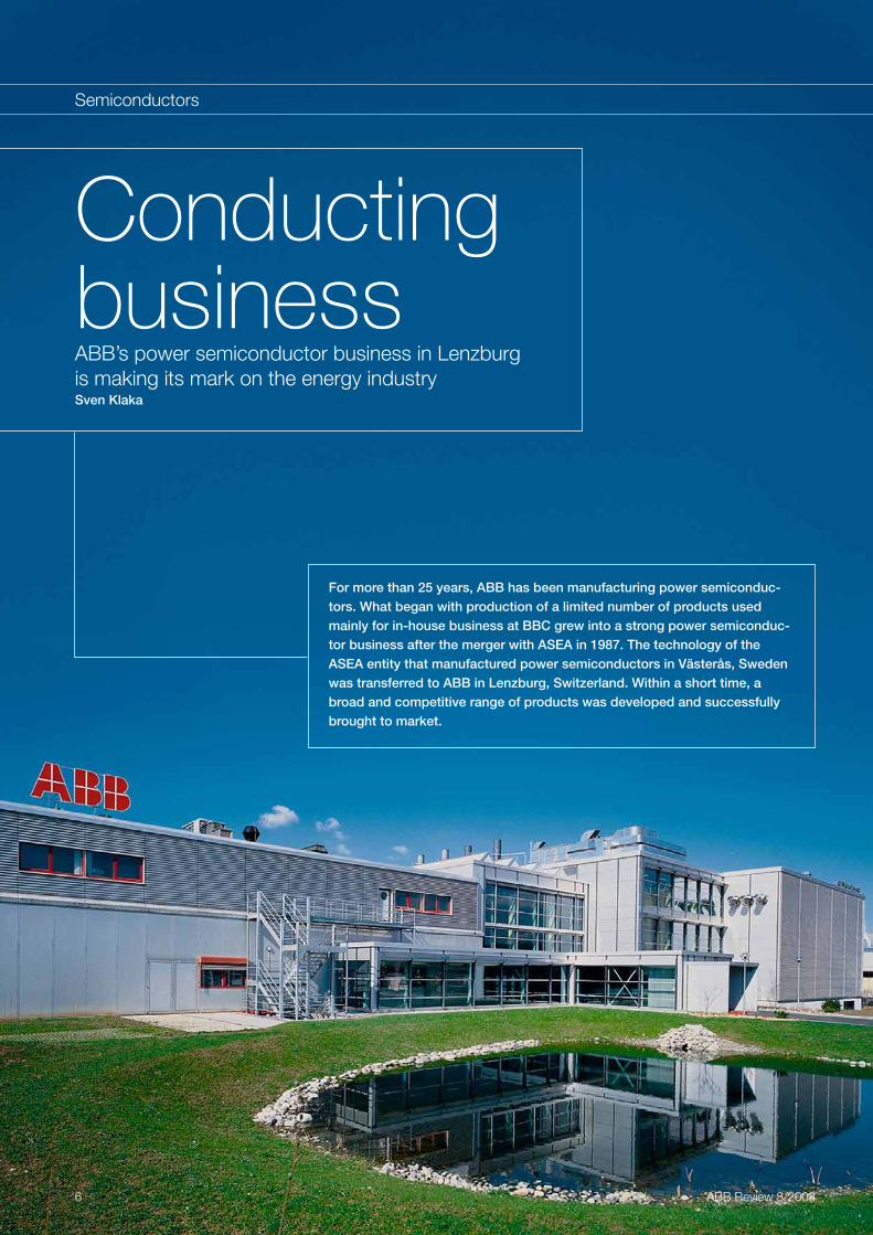
For more than 25 years, ABB has been manufacturing power semiconduc-tors. What began with production of a limited number of products used mainly for in-house business at BBC grew into a strong power semiconduc-tor business after the merger with ASEA in 1987. The technology of the ASEA entity that manufactured power semiconductors in Västerås, Sweden was transferred to ABB in Lenzburg, Switzerland. Within a short time, a broad and competitive range of products was developed and successfully brought to market.
Conducting businessABB’s power semiconductor business in Lenzburg is making its mark on the energy industrySven Klaka
7ABB Review 3/2008
Conducting business
Semiconductors
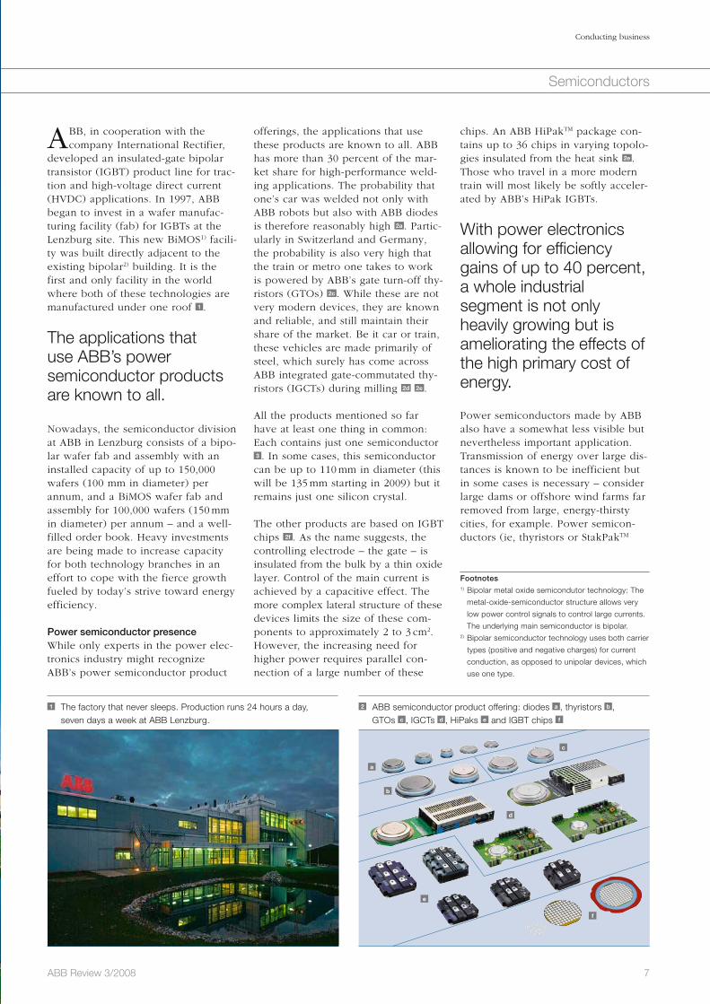
chips. An ABB HiPakTM package con-tains up to 36 chips in varying topolo-gies insulated from the heat sink 2e . Those who travel in a more modern train will most likely be softly acceler-ated by ABB’s HiPak IGBTs.
With power electronics allowing for efficiencygains of up to 40 percent, a whole industrialsegment is not only heavily growing but is ameliorating the effects of the high primary cost of energy.
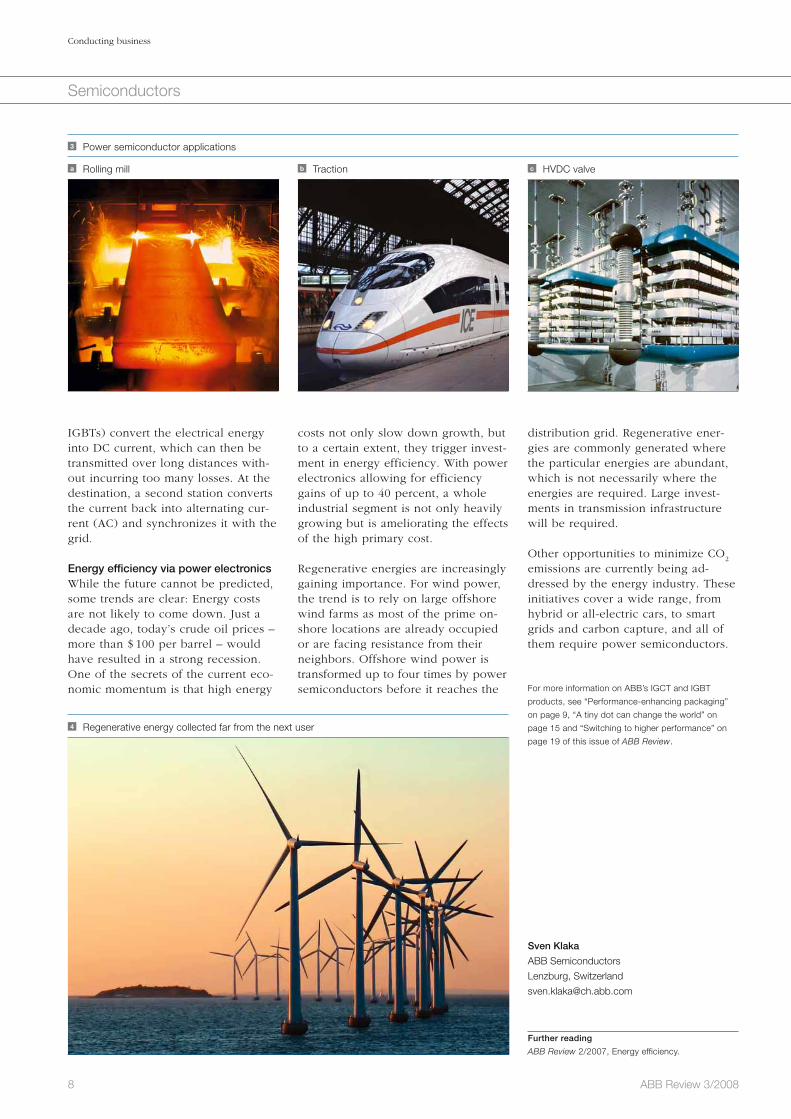
Power semiconductors made by ABB also have a somewhat less visible but nevertheless important application. Transmission of energy over large dis-tances is known to be inefficient but in some cases is necessary – consider large dams or offshore wind farms far removed from large, energy-thirsty cities, for example. Power semicon-ductors (ie, thyristors or StakPakTM
offerings, the applications that use these products are known to all. ABB has more than 30 percent of the mar-ket share for high-performance weld-ing applications. The probability that one’s car was welded not only with ABB robots but also with ABB diodes is therefore reasonably high 2a . Partic-ularly in Switzerland and Germany, the probability is also very high that the train or metro one takes to work is powered by ABB’s gate turn-off thy-ristors (GTOs) 2c . While these are not very modern devices, they are known and reliable, and still maintain their share of the market. Be it car or train, these vehicles are made primarily of steel, which surely has come across ABB integrated gate-commutated thy-ristors (IGCTs) during milling 2d 2e .
All the products mentioned so far have at least one thing in common: Each contains just one semiconductor 3 . In some cases, this semiconductor can be up to 110 mm in diameter (this will be 135 mm starting in 2009) but it remains just one silicon crystal.
The other products are based on IGBT chips 2f . As the name suggests, the controlling electrode – the gate – is insulated from the bulk by a thin oxide layer. Control of the main current is achieved by a capacitive effect. The more complex lateral structure of these devices limits the size of these com-ponents to approximately 2 to 3 cm2. However, the increasing need for higher power requires parallel con-nection of a large number of these
ABB, in cooperation with the company International Rectifier,
developed an insulated-gate bipolar transistor (IGBT) product line for trac-tion and high-voltage direct current (HVDC) applications. In 1997, ABB began to invest in a wafer manufac-turing facility (fab) for IGBTs at the Lenzburg site. This new BiMOS1) facili-ty was built directly adjacent to the existing bipolar2) building. It is the first and only facility in the world where both of these technologies are manufactured under one roof 1 .
The applications that use ABB’s power semiconductor products are known to all.
Nowadays, the semiconductor division at ABB in Lenzburg consists of a bipo-lar wafer fab and assembly with an installed capacity of up to 150,000 wafers (100 mm in diameter) per annum, and a BiMOS wafer fab and assembly for 100,000 wafers (150 mm in diameter) per annum – and a well-filled order book. Heavy investments are being made to increase capacity for both technology branches in an effort to cope with the fierce growth fueled by today’s strive toward energy efficiency.
Power semiconductor presenceWhile only experts in the power elec-tronics industry might recognize ABB’s power semiconductor product
1 The factory that never sleeps. Production runs 24 hours a day, seven days a week at ABB Lenzburg.
2 ABB semiconductor product offering: diodes a , thyristors b , GTOs c , IGCTs d , HiPaks e and IGBT chips f
Footnotes1) Bipolar metal oxide semicondutor technology: The
metal-oxide-semiconductor structure allows very
low power control signals to control large currents.
The underlying main semiconductor is bipolar. 2) Bipolar semiconductor technology uses both carrier
types (positive and negative charges) for current
conduction, as opposed to unipolar devices, which
use one type.
a
b
c
d
e
f
8 ABB Review 3/2008
Conducting business
Semiconductors
distribution grid. Regenerative ener-gies are commonly generated where the particular energies are abundant, which is not necessarily where the energies are required. Large invest-ments in transmission infrastructure will be required.
Other opportunities to minimize CO2
emissions are currently being ad-dressed by the energy industry. These initiatives cover a wide range, from hybrid or all-electric cars, to smart grids and carbon capture, and all of them require power semiconductors.
For more information on ABB’s IGCT and IGBT
products, see “Performance-enhancing packaging”
on page 9, “A tiny dot can change the world” on
page 15 and “Switching to higher performance” on
page 19 of this issue of ABB Review.
Sven Klaka
ABB Semiconductors
Lenzburg, Switzerland
Further reading
ABB Review 2/2007, Energy efficiency.
costs not only slow down growth, but to a certain extent, they trigger invest-ment in energy efficiency. With power electronics allowing for efficiency gains of up to 40 percent, a whole industrial segment is not only heavily growing but is ameliorating the effects of the high primary cost.
Regenerative energies are increasingly gaining importance. For wind power, the trend is to rely on large offshore wind farms as most of the prime on-shore locations are already occupied or are facing resistance from their neighbors. Offshore wind power is transformed up to four times by power semiconductors before it reaches the
IGBTs) convert the electrical energy into DC current, which can then be transmitted over long distances with-out incurring too many losses. At the destination, a second station converts the current back into alternating cur-rent (AC) and synchronizes it with the grid.
Energy efficiency via power electronicsWhile the future cannot be predicted, some trends are clear: Energy costs are not likely to come down. Just a decade ago, today’s crude oil prices – more than $ 100 per barrel – would have resulted in a strong recession. One of the secrets of the current eco-nomic momentum is that high energy
a Rolling mill
3 Power semiconductor applications
b Traction c HVDC valve
4 Regenerative energy collected far from the next user

9ABB Review 3/2008
Semiconductors
The role of integrated circuits (IC) packaging has expanded from that of protecting the integrity and performance of an IC, to being a central factor in the development of electronic system concepts. In fact, packaging technology is now a prime design consideration if increasingly stringent performance and reliability requirements are to be met. Thanks to a combination of tighter process toleranc-es, more accurate material-property measurement, and more intel-ligent substrate design and simulation, companies are designing more cost-effective module packages that outperform the more expensive previous-generation units.
The harsher the environment in which a module must function, the greater the demands on the packaging. The high reliability require-ments specified by the traction and industrial markets means that the family of HiPakTM modules developed by ABB has to ensure safe operation, high isolation and high DC-current capability, as well as being long lasting.
Performance- enhancing packagingDesigning an IGBT module packaging for high-quality and reliable operationDaniel Schneider, Lydia Feller, Dominik Trüssel, Samuel Hartmann, Sven Klaka

10 ABB Review 3/2008
Performance-enhancing packaging
Semiconductors
Firstly, a modular design means the main current path must be split into two. Wire bonds connect the chips with the substrate and main termi-nals connect the substrate with the busbar.
Secondly, the mismatch in thermal expansion between silicon and the other packaging materials makes it necessary to design flexible current leads if stress on the solder joints is to be minimized. This flexibility means that long leads with a small cross sectional area are preferred. Because this results in high electri-cal resistance, a compromise must be found if low resistance is to be maintained.
In today’s modules, a single terminal contact can have a rated current of up to 1,200 A. However, high ohmic heat-ing in the terminal means the modules cannot be operated at these high cur-rents over long periods of time with-out sufficient busbar cooling.
An ideal high current design, which aims to maintain low electrical resis-tance between the busbar and the chip, is important because a large part of the ohmic heat generated in the terminals flows in the direction of the busbar.1) The maximum temperature difference in the terminal is limited on the one hand by the maximum allow-able temperature of the packaging materials (for example the silicone gel) and on the other by the maxi-mum allowable busbar temperature. In general, a maximum temperature difference of 50 K within the terminal
stitutes the overall mechanical design, including the housing, silicone gel and epoxy filling.
The harsher the environ-ment the greater the demands on the module packaging.
As well as fulfilling the above-men-tioned four functions, the package design should enable the module to operate for at least 30 years. An infi-nite lifetime is not possible because of thermal cycles. In other words, modules undergo power load cycles. A train, for instance, may stop at a station for two minutes, allowing the module to cool down by several tens of degrees. An overnight stop means the temperature of the module will decrease from over 100 °C to the am-bient temperature. Such thermal cycles stress the module package in different ways. If two materials with different coefficients of thermal expansion (CTE) are joined together, they and the layer that joins them, for example solder joints, are particularly stressed whenever there is a temperature change. The contact between the bond wires and the chip metallization is also prone to failure when short cycles with low temperature differenc-es are applied.
The current path designThe use of an ideal contact, consisting of a stiff and wide copper bar, is limit-ed because of two issues:
ABB’s family of HiPak modules are high-power insulated-gate bipolar
transistors (IGBTs) in industry-stan-dard housings, and are based on ABB’s own soft-punch-through (SPT) and SPT+ technologies 1 . With foot-prints of 190 by 140 mm and 130 by 140 mm, they cover a wide voltage range from 1,200 to 6,500 V, and a current range from 400 up to 2,400 A [1, 2]. In addition, three different isola-tion voltage categories of 4, 6.2 and 10.2 kV
RMS are offered. These HiPak
modules are built in single IGBT, dual IGBT, dual diode and chopper config-urations.
Because of its application in the trac-tion and industrial markets, the pack-aging technology has to serve four main functions: It must provide a current path from the busbar to the chip and back.
The module must have an effective cooling system to prevent overheat-ing.
The electrical contacts must be iso-lated from each other.
The package needs to be mechani-cally robust.
These functions are controlled in dif-ferent parts of the HiPak module, a simplified cross section of which is shown in 2 . The parts in red illustrate the current path design, including the gate print, bond wires, and the main/auxiliary terminals. The thermal path design, including the base-plate and ceramic substrate is shown in blue. The area in green illustrates the elec-tric isolation design, which also con-
1 HiPak family 2 Cross section of a HiPak IGBT module
IGBT diode
a Coolerb Base-platec Solderd AIN-Ceramic insulator
e Cu metallizationf Silicone gelg Epoxyh Al bond wires
i Plastic casingj Gatek Connection to bus bars
a
b
de
f
gh
i
j k k
c
11ABB Review 3/2008
Performance-enhancing packaging
Semiconductors
each other’s magnetic field. In the HiPak modules, this means having collector and emitter conductors in very close proximity. However, a min-imum distance has to be maintained to prevent isolation damage.
Development trendsToday’s ABB HiPak modules are rated for terminal currents of 800 A for IGBTs and 1,200 A for diodes. New chip technologies, however, require even higher terminal current ratings of 1,500 A for diodes and 1,200 A for IGBTs. The ongoing development towards higher operating tempera-tures increases the urgency to design terminals with lower resistance and better cooling.
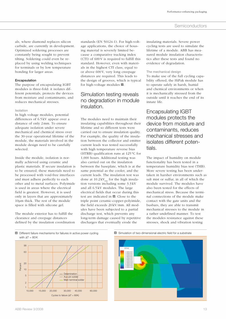
The thermal path designThe lower the thermal resistance between the IC and the cooling agent, the higher the output power of the module. Therefore, a good thermal contact will directly increase the mod-ule’s rating. A typical thermal imped-ance curve for IGBTs and diodes is shown in 6 . Within one second, ther-mal impedance reaches the static ther-mal resistance value. The time taken to reach stable temperatures is deter-mined by the heat capacity of the
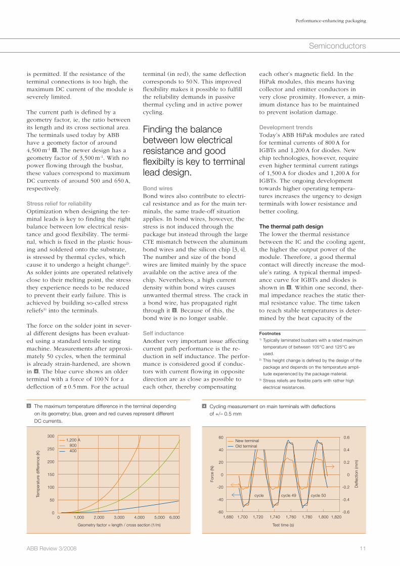
terminal (in red), the same deflection corresponds to 50 N. This improved flexibility makes it possible to fulfill the reliability demands in passive thermal cycling and in active power cycling.
Finding the balance between low electrical resistance and good f lexibilty is key to terminal lead design.
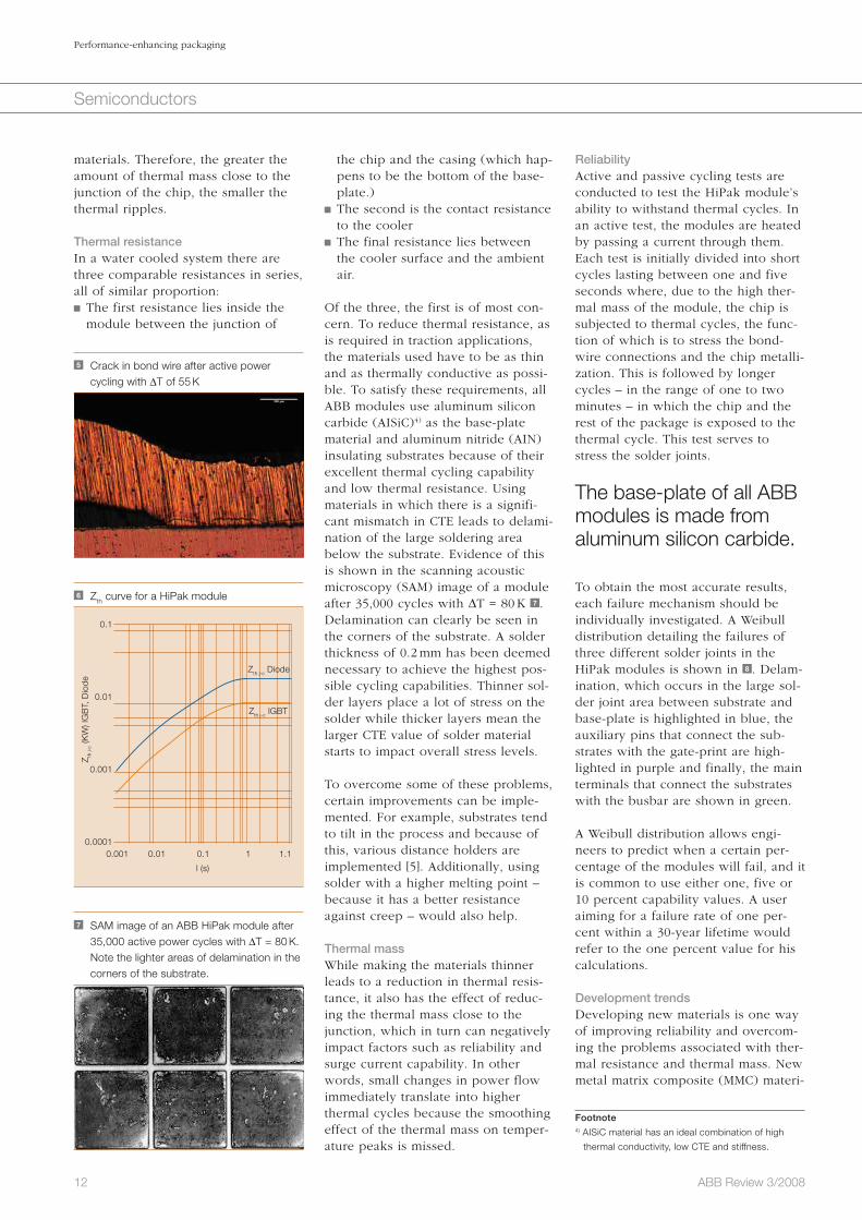
Bond wiresBond wires also contribute to electri-cal resistance and as for the main ter-minals, the same trade-off situation applies. In bond wires, however, the stress is not induced through the package but instead through the large CTE mismatch between the aluminum bond wires and the silicon chip [3, 4]. The number and size of the bond wires are limited mainly by the space available on the active area of the chip. Nevertheless, a high current density within bond wires causes unwanted thermal stress. The crack in a bond wire, has propagated right through it 5 . Because of this, the bond wire is no longer usable.
Self inductanceAnother very important issue affecting current path performance is the re-duction in self inductance. The perfor-mance is considered good if conduc-tors with current flowing in opposite direction are as close as possible to each other, thereby compensating
is permitted. If the resistance of the terminal connections is too high, the maximum DC current of the module is severely limited.
The current path is defined by a geometry factor, ie, the ratio between its length and its cross sectional area. The terminals used today by ABB have a geomety factor of around 4,500 m-1 3 . The newer design has a geometry factor of 3,500 m-1. With no power flowing through the busbar, these values correspond to maximum DC currents of around 500 and 650 A, respectively.
Stress relief for reliabilityOptimization when designing the ter-minal leads is key to finding the right balance between low electrical resis-tance and good flexibility. The termi-nal, which is fixed in the plastic hous-ing and soldered onto the substrate, is stressed by thermal cycles, which cause it to undergo a height change2). As solder joints are operated relatively close to their melting point, the stress they experience needs to be reduced to prevent their early failure. This is achieved by building so-called stress reliefs3) into the terminals.
The force on the solder joint in sever-al different designs has been evaluat-ed using a standard tensile testing machine. Measurements after approxi-mately 50 cycles, when the terminal is already strain-hardened, are shown in 4 . The blue curve shows an older terminal with a force of 100 N for a deflection of ± 0.5 mm. For the actual
3 The maximum temperature difference in the terminal depending on its geometry; blue, green and red curves represent different DC currents.
Geometry factor = length / cross section (1/m)
Tem
pera
ture
diff
eren
ce (K
)
300
250
200
150
100
50
00 1,000 2,000 3,000 4,000 5,000 6,000
1,200 A 800 400
4 Cycling measurement on main terminals with deflections of +/– 0.5 mm
Test time (s)
cycle cycle 49 cycle 50
Def
lect
ion
(mm
)
Forc
e (N
)
1,680 1,700 1,720 1,740 1,760 1,780 1,800 1,820
60
40
20
0
-20
-40
-60
0.6
0.4
0.2
0
-0.2
-0.4
-0.6
New terminal Old terminal
Footnotes1) Typically laminated busbars with a rated maximum
temperature of between 105°C and 125°C are
used.2) This height change is defined by the design of the
package and depends on the temperature ampli-
tude experienced by the package material. 3) Stress reliefs are flexible parts with rather high
electrical resistances.
12 ABB Review 3/2008
Performance-enhancing packaging
Semiconductors
ReliabilityActive and passive cycling tests are conducted to test the HiPak module’s ability to withstand thermal cycles. In an active test, the modules are heated by passing a current through them. Each test is initially divided into short cycles lasting between one and five seconds where, due to the high ther-mal mass of the module, the chip is subjected to thermal cycles, the func-tion of which is to stress the bond-wire connections and the chip metalli-zation. This is followed by longer cycles – in the range of one to two minutes – in which the chip and the rest of the package is exposed to the thermal cycle. This test serves to stress the solder joints.
The base-plate of all ABB modules is made from aluminum silicon carbide.
To obtain the most accurate results, each failure mechanism should be individually investigated. A Weibull distribution detailing the failures of three different solder joints in the HiPak modules is shown in 8 . Delam-ination, which occurs in the large sol-der joint area between substrate and base-plate is highlighted in blue, the auxiliary pins that connect the sub-strates with the gate-print are high-lighted in purple and finally, the main terminals that connect the substrates with the busbar are shown in green.
A Weibull distribution allows engi-neers to predict when a certain per-centage of the modules will fail, and it is common to use either one, five or 10 percent capability values. A user aiming for a failure rate of one per-cent within a 30-year lifetime would refer to the one percent value for his calculations.
Development trendsDeveloping new materials is one way of improving reliability and overcom-ing the problems associated with ther-mal resistance and thermal mass. New metal matrix composite (MMC) materi-
the chip and the casing (which hap-pens to be the bottom of the base-plate.)
The second is the contact resistance to the cooler
The final resistance lies between the cooler surface and the ambient air.
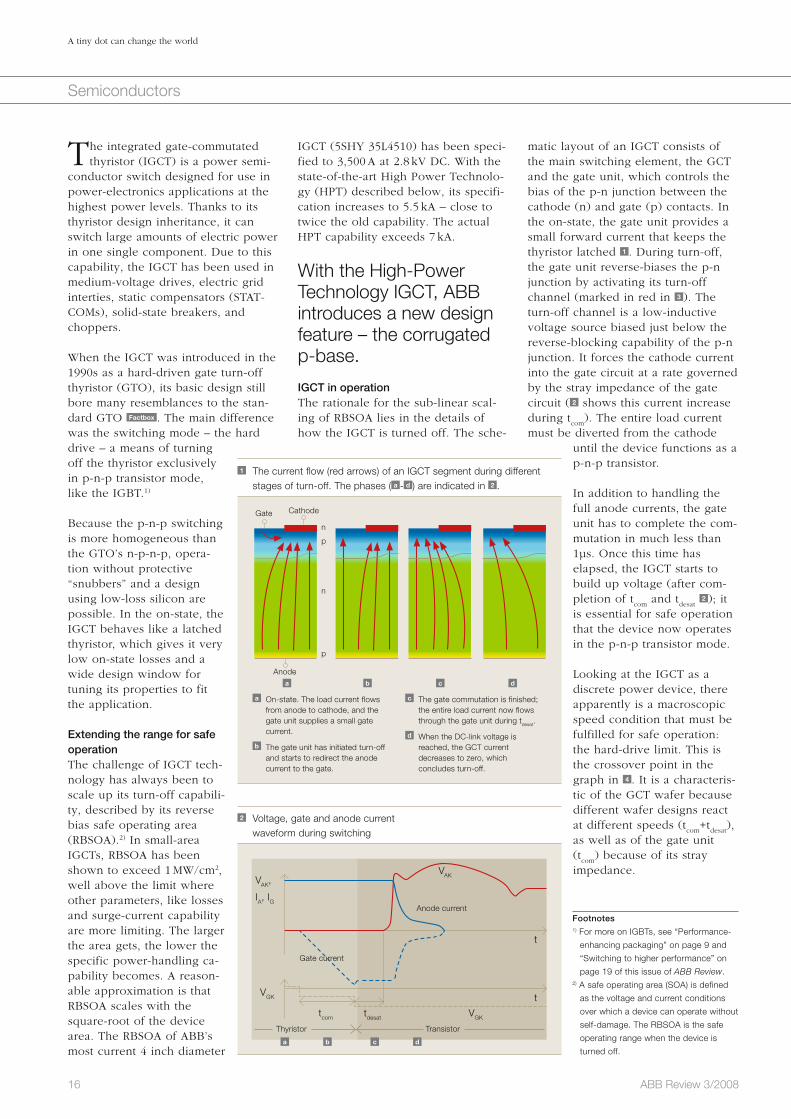
Of the three, the first is of most con-cern. To reduce thermal resistance, as is required in traction applications, the materials used have to be as thin and as thermally conductive as possi-ble. To satisfy these requirements, all ABB modules use aluminum silicon carbide (AISiC)4) as the base-plate material and aluminum nitride (AIN) insulating substrates because of their excellent thermal cycling capability and low thermal resistance. Using materials in which there is a signifi-cant mismatch in CTE leads to delami-nation of the large soldering area below the substrate. Evidence of this is shown in the scanning acoustic microscopy (SAM) image of a module after 35,000 cycles with ΔT = 80 K 7 . Delamination can clearly be seen in the corners of the substrate. A solder thickness of 0.2 mm has been deemed necessary to achieve the highest pos-sible cycling capabilities. Thinner sol-der layers place a lot of stress on the solder while thicker layers mean the larger CTE value of solder material starts to impact overall stress levels.
To overcome some of these problems, certain improvements can be imple-mented. For example, substrates tend to tilt in the process and because of this, various distance holders are implemented [5]. Additionally, using solder with a higher melting point – because it has a better resistance against creep – would also help.
Thermal massWhile making the materials thinner leads to a reduction in thermal resis-tance, it also has the effect of reduc-ing the thermal mass close to the junction, which in turn can negatively impact factors such as reliability and surge current capability. In other words, small changes in power flow immediately translate into higher thermal cycles because the smoothing effect of the thermal mass on temper-ature peaks is missed.
materials . Therefore, the greater the amount of thermal mass close to the junction of the chip, the smaller the thermal ripples.
Thermal resistanceIn a water cooled system there are three comparable resistances in series, all of similar proportion: The first resistance lies inside the module between the junction of
6 Zth curve for a HiPak module
0.001 0.01 0.1 1 1.1
l (s)
0.1
0.01
0.001
0.0001
Z th j-
c (K
W) I
GB
T, D
iode
Zth j-c IGBT
Zth j-c Diode
5 Crack in bond wire after active power cycling with ΔT of 55 K
7 SAM image of an ABB HiPak module after 35,000 active power cycles with ΔT = 80 K.
Note the lighter areas of delamination in the corners of the substrate.
Footnote4) AISiC material has an ideal combination of high
thermal conductivity, low CTE and stiffness.
13ABB Review 3/2008
Performance-enhancing packaging
Semiconductors
insulating materials. Severe power cycling tests are used to simulate the lifetime of a module. ABB has mea-sured module insulation characteris-tics after these tests and found no evidence of degradation.
The mechanical designTo make use of the full cycling capa-bility offered, the HiPak module has to operate safely in harsh, humid and chemical environments or when it is mechanically stressed from the outside until it reaches the end of its innate life.
Encapsulating IGBT modules protects the device from moisture and contaminants, reduces mechanical stresses and isolates different poten-tials.
The impact of humidity on module functionality has been tested in a temperature humidity bias test (THB). More severe testing has been under-taken in harsher environments such as salt mist or sulfur, in all of which the module survived. The modules have also been tested for the effects of mechanical stress. Because the termi-nal connections of the module make contact with the gate units and the busbars, they are able to transmit mechanical stresses to the module in a rather undefined manner. To test the modules resistance against these stresses, shock and vibration testing
standards (EN 50124-1). For high-volt-age applications, the choice of hous-ing material is severely limited be-cause a comparative tracking index (CTI) of 600 V is required to fulfill this standard. However, even with materi-als in the highest CTI class, equal to or above 600 V, very long creepage distances are required. This leads to the design of grooves, which is typical for high-voltage modules 1 .
Simulation testing reveals no degradation in module insulation.
The modules need to maintain their insulating capabilities throughout their lifetime and so different tests were carried out to ensure insulation quality. For example, the quality of the insula-tion between the collector and emitter current leads was tested successfully with high temperature reverse bias (HTRB) qualification runs at 125 °C for 1,000 hours. Additional testing was also carried out on the insulation between the baseplate, which is at the same potential as the cooler, and the current leads. The insulation test was done at 10.2 kV
rms for the high insula-
tion versions including some 3.3 kV and all 6.5 kV modules. The large electrical fields that occur during this test are indicated in 9 . Close to the triple point ceramic-copper-polyimide, the field exceeds 20 kV/mm. All mod-ules have been subjected to a partial discharge test, which prevents any long-term damage caused by repetitive discharges that eventually erode the
als, where diamond replaces silicon carbide, are currently in development. Optimized soldering processes are constantly being sought to prevent tilting. Soldering could even be re-placed by using welding techniques for terminals or by low temperature bonding for larger areas.
Encapsulation The purpose of encapsulating IGBT modules is three-fold: it isolates dif-ferent potentials, protects the devices from moisture and contaminants, and reduces mechanical stresses.
IsolationIn high voltage modules, potential differences of 6.5 kV appear over a distance of only 2 mm. To ensure adequate isolation under severe mechanical and chemical stress over the 30-year operational lifetime of the module, the materials involved in the module design need to be carefully selected.
Inside the module, isolation is nor-mally achieved using ceramic and plastic materials. If secure insulation is to be ensured, these materials need to be processed with void-free interfaces and must adhere perfectly to each other and to metal surfaces. Polyimide is used in areas where the electrical field is greatest. However, it is used only in layers that are approximately 10µm thick. The rest of the module space is filled with silicone gel.
The module exterior has to fulfill the clearance and creepage distances defined by the insulation coordination
9 Simulation of two-dimensional electric field for a substrate8 Different failure mechanisms for failures in active power cyclingwith ΔT = 80 K
Cycles to failure (ΔT = 80K)
Per
cent
10,000 15,000 20,000 30,000 40,000 60,000
99
63
20
10
5
2
1
Delamination Aux pin solder Main terminal solder

14 ABB Review 3/2008
Performance-enhancing packaging
Semiconductors
traction. Robustness translates into higher operating safety margins and allows low gate drive resistance at turn-off, which, in turn, allows lower turn-off losses. This is in keeping with ABB’s reputa-tion for offering high power semiconductors of exception-ally high reliability for the harshest of conditions.
An overview of the character-istics of the HiPak product family is given in 10 .
For more on IGBTs, see “Switching to
higher power” on page 19 of this issue of
ABB Review.
Daniel Schneider
Lydia Feller
Dominik Trüssel
Samuel Hartmann
Sven Klaka
ABB Semiconductors
Lenzburg, Switzerland
and higher currents leads to the ohmic heating of terminals. In other words, encapsulation materials are expected to perform very well at both low and high temperatures.
Setting new standardsTo find the right compromise between performance and reliability, different design variants have to be considered. ABB’s HiPak family of IGBT modules sets new standards of robustness for high reliability applications such as
was performed. To make the test more stressful, the HiPak modules were loaded with additional two kilogram bars on the main terminals and 250 g bars on the auxil-iary terminals. Despite these severe conditions, absolutely no problems were detected. This outstanding perfor-mance is possible, thanks to a thick epoxy layer filled with glass fibers and miner-als.
Unfortunately, a good design and thorough testing cannot guarantee zero failures. In fact, standard failure rates are of the order of several hundred failures in time (FITs), where one FIT equals one module failure in one billion device-operating hours. In this case, it is im-portant that the modules fail safely, with the lowest possi-ble impact on neighboring equipment and with zero impact on human beings. Therefore, ABB has chosen a robust design with a thick epoxy layer, which helps to absorb (while directing side-ways) energy in case of an explosion. Furthermore, the chosen materials have been certified according to the flammability stan-dards (UL 94 and NF F 16-102). There-fore in the case of a fire, the materials extinguish without developing toxic gases.
ABB’s HiPak family of IGBT modules sets new standards of robustness for reliability in harsh conditions.
Development trendsTwo development directions are im-portant for encapsulation. To enable operation in Siberia and Tibet, the storage or operating temperature range has been extended down to – 55 °C. At the other extreme, the trend towards higher operating tem-peratures of up to 150 °C and beyond,
10 Overview of ABB’s qualification program for HiPak modules
Test
Conditions Standard
Active power cycling (case)
tcycle = 1-2 mins, ΔTcase = 60-80 K
IEC 60747-9, 60749-34
Active power cycling (junction)
tcycle = 1-5 s, ΔTj = 40-80 K IEC 60747-9, 60749-34
Passive thermal cycling
tcycle = 4 h, ΔT = 165-200 K IEC 60068-2-14
High temperature reverse bias
Vce = 5200 V, 125°C, 1000 h IEC 60747–9.8
High temperature gate bias
Vge = +/-20 V, 125°C, 1000 h
IEC 60749-9.8
Temperature humidity bias
Vce = 80 V, 85°C, 85%, 1000 h
IEC 60749–3.4B
Salt mist
50 g/l NaCl, 35°C, 16 h IEC 60068-2-11
Sulfur (SO2, H2S)
25°C, 75 percent, 10 days IEC 60068-2-60
Shock and vibration
IEC 61373
Fire protection
UL 94 : V0, NF F 16-101 : I3/F2
References
[1] Rahimo, M. et al. (2004). 2.5 kV–6.5 kV Industry standard IGBT modules setting a new benchmark in
SOA capability. Proc. PCIM, 314–319, Nürnberg, Germany.
[2] Rahimo, M. et al. (2005). SPT+, The next generation of low-loss HV-IGBTs. Proc. PCIM, 361–366,
Nürnberg, Germany.
[3] Yamada, Y. et al. (2007). Reliability of wire-bonding and solder joint for high temperature operation of power
semiconductor device, Microelectronics Reliability 47 2147–2151.
[4] Horio, M. et al. (2007). Investigations of high temperature IGBT module package structure. Proc. PCIM,
Nürnberg, Germany.
[5] K. Guth, K., Mahnke, P. (2006). Improving the thermal reliability of large area solder joints in IGBT power
modules. Proc. CIPS, Naples, Italy.
15ABB Review 3/2008
Semiconductors
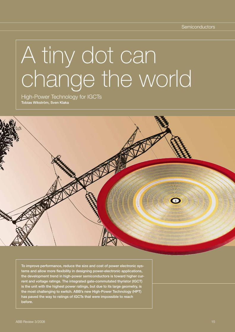
A tiny dot can change the worldHigh-Power Technology for IGCTsTobias Wikström, Sven Klaka
To improve performance, reduce the size and cost of power electronic sys-tems and allow more flexibility in designing power-electronic applications, the development trend in high-power semiconductors is toward higher cur-rent and voltage ratings. The integrated gate-commutated thyristor (IGCT) is the unit with the highest power ratings, but due to its large geometry, is the most challenging to switch. ABB’s new High-Power Technology (HPT) has paved the way to ratings of IGCTs that were impossible to reach before.
16 ABB Review 3/2008
A tiny dot can change the world
Semiconductors
matic layout of an IGCT consists of the main switching element, the GCT and the gate unit, which controls the bias of the p-n junction between the cathode (n) and gate (p) contacts. In the on-state, the gate unit provides a small forward current that keeps the thyristor latched 1 . During turn-off, the gate unit reverse-biases the p-n junction by activating its turn-off channel (marked in red in 3 ). The turn-off channel is a low-inductive voltage source biased just below the reverse-blocking capability of the p-n junction. It forces the cathode current into the gate circuit at a rate governed by the stray impedance of the gate circuit ( 2 shows this current increase during t
com). The entire load current
must be diverted from the cathode until the device functions as a p-n-p transistor.
In addition to handling the full anode currents, the gate unit has to complete the com-mutation in much less than 1µs. Once this time has elapsed, the IGCT starts to build up voltage (after com-pletion of t
com and t
desat 2 ); it
is essential for safe operation that the device now operates in the p-n-p transistor mode.
Looking at the IGCT as a discrete power device, there apparently is a macroscopic speed condition that must be fulfilled for safe operation: the hard-drive limit. This is the crossover point in the graph in 4 . It is a characteris-tic of the GCT wafer because different wafer designs react at different speeds (t
com+t
desat),
as well as of the gate unit (t
com) because of its stray
impedance.
IGCT (5SHY 35L4510) has been speci-fied to 3,500 A at 2.8 kV DC. With the state-of-the-art High Power Technolo-gy (HPT) described below, its specifi-cation increases to 5.5 kA – close to twice the old capability. The actual HPT capability exceeds 7 kA.
With the High-Power Technology IGCT, ABB introduces a new design feature – the corrugated p-base.
IGCT in operationThe rationale for the sub-linear scal-ing of RBSOA lies in the details of how the IGCT is turned off. The sche-
The integrated gate-commutated thyristor (IGCT) is a power semi-
conductor switch designed for use in power-electronics applications at the highest power levels. Thanks to its thyristor design inheritance, it can switch large amounts of electric power in one single component. Due to this capability, the IGCT has been used in medium-voltage drives, electric grid interties, static compensators (STAT-COMs), solid-state breakers, and choppers.
When the IGCT was introduced in the 1990s as a hard-driven gate turn-off thyristor (GTO), its basic design still bore many resemblances to the stan-dard GTO Factbox . The main difference was the switching mode – the hard drive – a means of turning off the thyristor exclusively in p-n-p transistor mode, like the IGBT.1)
Because the p-n-p switching is more homogeneous than the GTO’s n-p-n-p, opera-tion without protective “snubbers” and a design using low-loss silicon are possible. In the on-state, the IGCT behaves like a latched thyristor, which gives it very low on-state losses and a wide design window for tuning its properties to fit the application.
Extending the range for safe operationThe challenge of IGCT tech-nology has always been to scale up its turn-off capabili-ty, described by its reverse bias safe operating area (RBSOA).2) In small-area IGCTs, RBSOA has been shown to exceed 1 MW/cm2, well above the limit where other parameters, like losses and surge-current capability are more limiting. The larger the area gets, the lower the specific power-handling ca-pability becomes. A reason-able approximation is that RBSOA scales with the square-root of the device area. The RBSOA of ABB’s most current 4 inch diameter
1 The current flow (red arrows) of an IGCT segment during different stages of turn-off. The phases ( a - d ) are indicated in 2 .
a b c d
Gate Cathode
a On-state. The load current flows from anode to cathode, and the gate unit supplies a small gate
current.
b The gate unit has initiated turn-off and starts to redirect the anode current to the gate.
c The gate commutation is finished; the entire load current now flows through the gate unit during tdesat.
d When the DC-link voltage is reached, the GCT current
decreases to zero, which concludes turn-off.
n
p
p
n
Anode
2 Voltage, gate and anode current waveform during switching
Anode current
Gate current
VAK
VGK
t
t
tcom tdesat VGK
VAK,
IA, IG
TransistorThyristor
a b c d
Footnotes1) For more on IGBTs, see “Performance-
enhancing packaging” on page 9 and
“Switching to higher performance” on
page 19 of this issue of ABB Review.2) A safe operating area (SOA) is defined
as the voltage and current conditions
over which a device can operate without
self-damage. The RBSOA is the safe
operating range when the device is
turned off.

17ABB Review 3/2008
A tiny dot can change the world
Semiconductors
imbalance affects primarily the outer-most rings. This is also confirmed by experiments – the vast majority of segment rings resulting in RBSOA fail-ures are the outermost rings.
This inductance imbalance is a result of mechanical constraints in the IGCT package assembly. Subsequently, the GCT device will inevitably be subject to some current redistribution as the gate signal propagates over the wafer. This is the second reason why scaling up the area makes life tougher for the IGCT: The cells remotest from the gate contact become loaded with a higher stray inductance. The only antidote from a silicon-technology perspective is to make a wafer that shows less sensitivity to impedance imbalance.
redistribution. The segments are arranged in 10 segment rings on the wafer. The gate contact is ring-shaped and located between segment rings five and six.
Unavoidably, these segment rings have slightly different impedances to the gate unit. A simulation of the wafer, housing and gate-unit geometry reveals the different stray inductance load of individual segment rings de-pendent on the ring number 5 . This imbalance results only from the con-straints on how the current flows from the wafer to the gate unit. Considering that the active area of a segment ring increases with the square of the ring number, the current is by far the larg-est in the outermost rings. Hence it is to be expected that the impact of this
Challenges of the real deviceLarge-area devices are more challeng-ing because the higher the current, the harder the demands regarding the gate-circuit stray impedance.
The title picture of this article shows the latest 5.5 kA GCT wafer with thou-sands of parallel GCT-segment con-nections, all of which need to be syn-chronously operated to avoid current
Turn-off circuit
3 A schematic circuit diagram of the IGCT with the gate unit and its outside connections on the left, and the GCT power semiconductor on the right
IGCT
Internal supply(No galvanic isolation to power circuit)
Logicmonitor-
ing
Turn-on
circuit
Gate unit
X1
CS
Tx
LED1LED2LED3LED4
Rx
SF
Supply (VGN)
Command signal (light) Cathode
Gate
Anode
Status feedback (light)
GCT
4 The current dependence of tcom and tcom+tdesat shown for the improved HPT technology (red) and conventional technology (blue)
600
500
400
300
200
100
00 1000 2000 3000 4000 5000 6000
ITGQ [A]
5 The stray inductance of the individual segment rings on a GCT wafer as a function of their placement
6
5
4
3
2
1
Ring number (1 = Innermost)
Tim
e (n
s)
Gate contact
0 1 2 3 4 5 6 7 8 9 10 11
Factbox GTOs
Normal thyristors can only be turned on but cannot be turned off. Thyristors are switched on by a gate signal, but even after the gate signal is removed, the thyristor remains in the on-state. A gate turn-off thyristor (GTO), on the other hand, can also be turned off by a gate signal of negative polarity.
Turn-on is realized by a positive current pulse between the gate and cathode con-nections. To keep the GTO in on-status, a small positive gate current must be pro-vided.
Turn-off is made by a negative voltage pulse between the gate and cathode. About one-third to one-fifth of the forward current is diverted, which induces a cath-ode-gate voltage and transfers the GTO into the blocking status. The turn-off phase takes some time until all charges are removed from the device. The maxi-mum frequency for GTO application is thus restricted to about 1 kHz.
tdesat + tcom, improved gate unit tcom, improved gate unit tdesat + tcom, conventional gate unit tcom, conventional gate unit
Gat
e-ci
rcui
t st
ray
indu
ctan
ce (n
H)

18 ABB Review 3/2008
A tiny dot can change the world
Semiconductors
Combining these advantages, it is highly possible that in the near future, larger IGCTs will be capable of switching more than 4 kA against DC voltages of more than 6 kV, enabling three-level 20 MW medium-voltage drives for 6 kV AC motors without any need for series or parallel connection.
At the other end of the application range, due to the enormous turn-off capability in combination with a po-tentially thyristor-like on-state voltage drop, additional possibilities arise for the use of IGCTs as wear-resistant static circuit breakers.
For more on ABB’s IGCT and IGBT product offerings,
see “Conducting business” on page 6 of this issue of
ABB Review.
Tobias Wikström
Sven Klaka
ABB Semiconductors
Lenzburg, Switzerland
With its new robustness, the HPT IGCT is also able to withstand switch-ing self-clamping mode (SSCM), which is a harsh benchmark of ruggedness extensively described in connection with IGBTs over the last few years.
The robust High-Power Technology IGCT is able to withstand switching self-clamping mode (SSCM), which is a harsh benchmark of ruggedness.
. . . and its future developmentApart from the immediate benefits mentioned above, this novel technolo-gy allows future expansions of the IGCT range: 10 kV IGCTs will have competitive turn-off current ratings comparable with today’s ratings of 6 kV devices.
In principle, HPT will allow for better homogeneity of the turn-off process over the diameter of the wafer.
A further increase of the wafer diameter appears feasible.
With the HPT IGCT, ABB introduces a new design feature – the corrugated p-base. In 6 , the main characteristics of this technology are sketched: In conventional technology, the p-base diffusion is homogeneous over the whole wafer. In HPT technology, the lower p-diffusion layer is masked underneath the cathode fingers. As a result, the p-base has a corrugated appearance. Together with the new gate unit, it has a substantial impact on RBSOA. It is breathtaking that such a tiny spot with reduced doping can in fact make this tremendous change.
The new capability . . .The HPT technology is available in 4.5 kV and 6.5 kV asymmetric IGCT versions. 7 shows the new ABB design of an IGCT with HPT.
With HPT technology, the destruction limit of the IGCT has increased by 50 percent at 125 °C and by 80 per-cent at room temperature. The IGCT demonstrates a negative temperature coefficient of maximum controllable current, illustrating that the device is now limited in the same way as IGBTs 8 .
7 The new HPT IGCT from ABB, available in 4.5kV and 6.5kV variants
6 The structure and doping design of a conventional GCT cell (left), and the HPT technology with the corrugated p-base (right)
Gate GateGate GateCathode Cathode
n+ n+
n-n-
p- p-
p+ p+
8 The maximum turn-off current of the HPT compared with the conventional IGCT
specification
VDC = 2800 V, Ls = 300 nH
HPT GCT
0 50 100 150
Specification 5SHY 35L4510
Tj (°C)
I TGQ
M (k
A)
8
6
4
2
As only a conventional reference exists for 4.5 kV, these results are shown here.

19ABB Review 3/2008
Semiconductors
Two decades ago, a seemingly simple variant of the silicon power MOSFET began to change the power electronic landscape: the insulated-gate bipolar transistor (IGBT). This revolution has continued throughout the 1990s and into the new millennium. The IGBT presents interesting characteristics combining both MOS and bipolar structures with highly advantageous features for power system designers – mainly its low losses, its high input impedance permitting the use of comparatively small gate drivers, and its short-circuit withstand capability and robust turn-off performance.
Switching to higher performanceThe evolution of IGBT technologyMunaf Rahimo, Arnost Kopta
While the first commercially available IGBTs did not exceed blocking volt-ages above 600V, and currents of a few amperes, development trends focused on increasing the power han-dling capability. Today, high-voltage IGBTs and their counterpart diodes (with ratings of up to 6.5 kV) are being manufactured successfully for 3.6 kV DC-link applications. In addition, high-current IGBT modules with large numbers of chips in parallel are employed in many applications with current ratings of up to 3,600 A. The availability of such a wide range of current and voltage ratings has result-
ed in the utilization of the IGBT in many power electronic applications; these include traction, HVDC and industrial drives with the respective emphasis on the differing perfor-mance requirements of each type of application. In this article, the latest development trends in IGBT and diode design are presented. These have enabled these devices to make a considerable leap forwards in terms of performance. An outlook into future development trends, targeting further improvements in the IGBT and diode characteristics, is also looked into.
ABB Review 3/2008

20 ABB Review 3/2008
Switching to higher performance
Semiconductors
limits. The new technology enabled the devices to withstand the critical and formerly unsustainable phase of dynamic avalanche and resulted in a remarkable increase of ruggedness. Thus, the high-voltage IGBTs were able to reach a new operational mode referred to as the switching-self-clamp-ing-mode (SSCM) as the overshoot voltage reaches levels close to that of the static breakdown voltage. It was demonstrated that the IGBT could r emarkably still withstand such condi-tions, leading to an ultimate square SOA behavior. This mode of operation can be seen in the 3.3 kV/1,200 A IGBT module RBSOA waveforms shown in 1a and the associated square SOA I/V curve in 1b . Similar improvements were also achieved for the short-circuit SOA capability of the IGBT and the reverse recovery SOA for the anti-par-allel diode.
SPT+: Lower losses and larger SOAThe next milestone was the reduction of the total losses of the IGBT and
diode without sacrificing the performance advantages men-tioned above. The SPT+ IGBT platform was designed to sub-stantially reduce on-state volt-age while increasing the high turn-off ruggedness to above that of the SPT technology. ABB’s SPT+ IGBT technology permitted the company to establish a new technology curve benchmark over the whole IGBT voltage range from 1,200 V to 6,500 V 2 . The values for V
ce(sat) are obtained
at the same current densities and for similar turn-off losses
especially for high voltage devices – system designers had no choice but to resign themselves to a number of operational limits to be able to attain the necessary switching capability. These measures included de-rating and the use of voltage clamps, snub-bers and high gate resistances.
The SPT+ technology not only offers significantly lower losses but also an increased SOA capability as compared to the standard technology.
It was the introduction of the soft-punch-through (SPT) concept featuring thinner silicon, combined with a high-ly-rugged planar cell-design platform, substantially increasing the cell latch-up immunity, that allowed lower losses to be achieved. The change also her-alded a clear breakthrough in SOA
The power electronics community upholds a long wish list of im-
provements targeted at the electrical performance of power semiconductor devices. Despite the fact that the IGBT offers the user a broad range of attrac-tive electrical characteristics, improve-ments on these are continuously being demanded. Over the past years, the main development trend for power semiconductors was aimed at increas-ing the power density for a given tar-geted application. From the device viewpoint, the limitations are three fold: First the total losses in the device Second the safe operating area (SOA) boundaries
And finally the maximum allowable junction temperature during opera-tion
Moreover, a further limitation exists for the removal of the power dissipat-ed in the device. However, this chal-lenge remains a focus of package and system cooling developments. Recent power semiconductor devel-opments at ABB were main-ly aimed at tackling the first two limits, especially for high-voltage devices.
SPT: The SOA breakthroughTrends for the development of IGBTs and diodes have always been aimed at ob-taining a sufficiently large SOA as required by many power electronic systems operating under hard-switch-ing conditions. Until recent-ly, in order to overcome the insufficient ruggedness –
a RBSOA current and voltage waveforms
1 3.3 kV/1,200 A IGBT module RBSOA at 125 °C (VDC = 2,600 V, IC = 5,000 A, RG = 1.5 Ω, LS = 280 nH)
b I/V square RBSOA curve
Time (500 nsec/div)Voltage (V)
0 500 1000 1500 2000 2500 3000 3500 4000 4500
30
25
20
15
10
5
0
-5
-10
-15
-20
-25
Vge
Vce
Ic
SSCM
Vge
(V)
5500
5000
4500
4000
3500
3000
2500
2000
1500
1000
500
0
5500
5000
4500
4000
3500
3000
2500
2000
1500
1000
500
0
Time
Data sheet SOA
SSCMIc (A
), V
ce (V
)
curr
ent
(A)
2 SPT+ IGBT on-state Vce(sat) reduction for voltage ratings up to 6,500 V
5.5
5.0
4.5
4.0
3.5
3.0
2.5
2.0
1.50 500 1000 1500 2000 2500 3000 3500 4000 4500 5000 5500 6000 6500 7000
VC
E, on
(V)
Voltage class (V)
SPT
SPT+
HV-IGBTs

21ABB Review 3/2008
Switching to higher performance
Semiconductors
sary. A better trade-off between total diode losses and recovery softness was achieved due to the improved shape of the stored electron-hole plasma.
the stored charge. Due to the improved charge distribution, the overall losses could be reduced while maintaining the soft recovery characteristics of standard SPT diodes.
On the anode side, the SPT+ diode employs the same design as used in the standard SPT technology, utilizing a strongly-doped P+-emitter. The anode emitter efficiency is adjusted using a first He++ peak placed inside the P+-diffusion. In order to control the plasma concentration in the N-base region and on the cathode side of the diode, a second He++ peak is implanted deeply in the N-base from the cathode side. In this way, a double local lifetime profile is achieved as shown in 4 . With this approach, no additional homogenous lifetime control in the N-base is neces-
for each voltage class. In the follow-ing sections of this article, the new SPT+ IGBT and diode performance are explained and demonstrated with the example of a high-voltage 6.5 kV module.
SPT+ IGBT and Diode technologyThe advanced SPT+ IGBT performance was achieved by combining an im-proved planar cell design with the already well-optimized vertical struc-ture utilized in the SPT technology. A cross-section of the SPT+ IGBT is shown in 3 . The planar SPT+ technol-ogy employs an N-enhancement layer surrounding the P-well in the IGBT cell. The N-layer improves the carrier concentration on the cathode side of the IGBT, thus lowering the on-state voltage drop (V
CE,on) without signifi-
cantly increasing the turn-off losses. A further reduction of V
CE,on was
achieved by reducing the channel resistance by shortening the lateral length of the MOS-channel. By opti-mizing the shape of the N-enhance-ment layer, the turn-off ruggedness SOA of the SPT+ cell could be in-creased beyond the level of the already very rugged standard SPT cell. In this way, the SPT+ technology not only offers significantly lower losses but also an increased SOA capability as compared to the standard technology.
4 shows a cross-section of the SPT+ diode. The SPT+ diode technology utilizes a double local lifetime-control technique to optimize the shape of
3 SPT+ IGBT technology
Emitter
Gate
P P
Short channel
N-base
Collector
N-enhancement layer
P+
SPT-buffer
4 SPT+ diode technology
Anode
N-base
N+
N-buffer
Cathode
P+
Carrier lifetime
Locallifetimecontrol
5 The 6.5 kV HV-HiPak module comprising the newly developed SPT+ chip-set
6 Forward characteristics of the 6.5 kV SPT+ IGBT (module level measurements)
1500
1250
1000
750
500
250
0
VCE (V)
I C (A
)
Tvj = 25°C
Tvj = 125°C
0 1 2 3 4 5 6 7 8
Nominal current
7 6.5 kV SPT+ IGBT turn-off under nominal conditions measured at module level
800
700
600
500
400
300
200
100
0
-100
-200
5000
4500
4000
3500
3000
2500
2000
1500
100
500
0
0 2 4 6 8 10 12 14 16 18 20
Ic = 750 A, VDC = 3600 V, Tj = 125 °C, Ls = 280 nH
Time (μs)
I C (A
), 10
*VG
E (V
)
VC
E (V
)
VGE
IC
VCE
22 ABB Review 3/2008
Switching to higher performance
Semiconductors
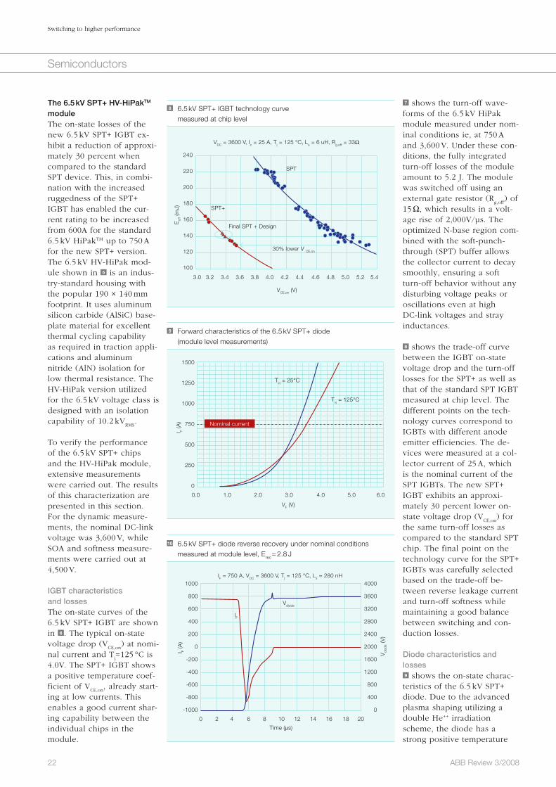
7 shows the turn-off wave-forms of the 6.5 kV HiPak module measured under nom-inal conditions ie, at 750 A and 3,600 V. Under these con-ditions, the fully integrated turn-off losses of the module amount to 5.2 J. The module was switched off using an external gate resistor (R
g,off) of
15 Ω, which results in a volt-age rise of 2,000V/µs. The optimized N-base region com-bined with the soft-punch-through (SPT) buffer allows the collector current to decay smoothly, ensuring a soft turn-off behavior without any disturbing voltage peaks or oscillations even at high DC-link voltages and stray inductances.
8 shows the trade-off curve between the IGBT on-state voltage drop and the turn-off losses for the SPT+ as well as that of the standard SPT IGBT measured at chip level. The different points on the tech-nology curves correspond to IGBTs with different anode emitter efficiencies. The de-vices were measured at a col-lector current of 25 A, which is the nominal current of the SPT IGBTs. The new SPT+ IGBT exhibits an approxi-mately 30 percent lower on-state voltage drop (V
CE,on) for
the same turn-off losses as compared to the standard SPT chip. The final point on the technology curve for the SPT+ IGBTs was carefully selected based on the trade-off be-tween reverse leakage current and turn-off softness while maintaining a good balance between switching and con-duction losses.
Diode characteristics and losses9 shows the on-state charac-teristics of the 6.5 kV SPT+ diode. Due to the advanced plasma shaping utilizing a double He++ irradiation scheme, the diode has a strong positive temperature
The 6.5 kV SPT+ HV-HiPakTM moduleThe on-state losses of the new 6.5 kV SPT+ IGBT ex-hibit a reduction of approxi-mately 30 percent when compared to the standard SPT device. This, in combi-nation with the increased ruggedness of the SPT+ IGBT has enabled the cur-rent rating to be increased from 600A for the standard 6.5 kV HiPakTM up to 750 A for the new SPT+ version. The 6.5 kV HV-HiPak mod-ule shown in 5 is an indus-try-standard housing with the popular 190 × 140 mm footprint. It uses aluminum silicon carbide (AlSiC) base-plate material for excellent thermal cycling capability as required in traction appli-cations and aluminum nitride (AlN) isolation for low thermal resistance. The HV-HiPak version utilized for the 6.5 kV voltage class is designed with an isolation capability of 10.2 kV
RMS.
To verify the performance of the 6.5 kV SPT+ chips and the HV-HiPak module, extensive measurements were carried out. The results of this characterization are presented in this section. For the dynamic measure-ments, the nominal DC-link voltage was 3,600 V, while SOA and softness measure-ments were carried out at 4,500 V.
IGBT characteristics and lossesThe on-state curves of the 6.5 kV SPT+ IGBT are shown in 6 . The typical on-state voltage drop (V
CE,on) at nomi-
nal current and Tj=125 °C is
4.0V. The SPT+ IGBT shows a positive temperature coef-ficient of V
CE,on, already start-
ing at low currents. This enables a good current shar-ing capability between the individual chips in the module.
10 6.5 kV SPT+ diode reverse recovery under nominal conditions measured at module level, Erec = 2.8 J
1000
800
600
400
200
0
-200
-400
-600
-800
-1000
4000
3600
3200
2800
2400
2000
1600
1200
800
400
0
0 2 4 6 8 10 12 14 16 18 20
IF = 750 A, VDC = 3600 V, Tj = 125 °C, Ls = 280 nH
Time (μs)
Vdi
ode
(V)
I F (A
)
IF
Vdiode
8 6.5 kV SPT+ IGBT technology curve measured at chip level
240
220
200
180
160
140
120
100
3.0 3.2 3.4 3.6 3.8 4.0 4.2 4.4 4.6 4.8 5.0 5.2 5.4
VDC = 3600 V, Ic = 25 A, Tj = 125 °C, Ls = 6 uH, Rg.off = 33Ω
SPT
Final SPT + Design
VCE,on (V)
Eof
f (m
J) SPT+
30% lower V CE,on
9 Forward characteristics of the 6.5 kV SPT+ diode (module level measurements)
1500
1250
1000
750
500
250
0
0.0 1.0 2.0 3.0 4.0 5.0 6.0
VF (V)
Nominal current
Tvj = 25°C
Tvj = 125°C
I F (A
)
23ABB Review 3/2008
Switching to higher performance
Semiconductors
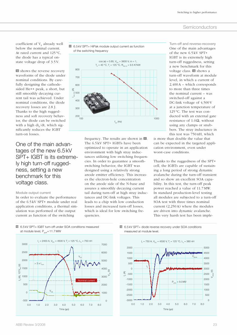
Turn-off and reverse-recovery One of the main advantages of the new 6.5 kV SPT+ IGBT is its extremely high turn-off ruggedness, setting a new benchmark for this voltage class. 12 shows a turn-off waveform at module level, in which a current of 2,400 A – which corresponds to more than three times the nominal current – was switched-off against a DC-link voltage of 4,500 V at a junction temperature of 125 °C. The test was con-ducted with an external gate resistance of 1.0 Ω, without using any clamps or snub-bers. The stray inductance in this test was 750 nH, which
is more than double the value that can be expected in the targeted appli-cation environment, even under worst-case conditions.
Thanks to the ruggedness of the SPT+ cell, the IGBTs are capable of sustain-ing a long period of strong dynamic avalanche during the turn-off transient and so show an excellent SOA capa-bility. In this test, the turn-off peak power reached a value of 11.7 MW. In standard production-level testing all modules are subjected to a turn-off SOA test with three times nominal current (2,250 A) where the modules are driven into dynamic avalanche. This very harsh test has been imple-
frequency. The results are shown in 11 . The 6.5 kV SPT+ IGBTs have been optimized to operate in an application environment with high stray induc-tances utilizing low switching frequen-cies. In order to guarantee a smooth-switching behavior, the IGBT was designed using a relatively strong anode emitter efficiency. This increas-es the electron-hole concentration on the anode side of the N-base and assures a smoothly decaying current tail during turn-off at high stray induc-tances and DC-link voltages. This leads to a chip with low conduction losses and increased turn-off losses, which is ideal for low switching fre-quencies.
coefficient of VF already well
below the nominal current. At rated current and 125 °C, the diode has a typical on-state voltage drop of 3.5 V.
10 shows the reverse recovery waveforms of the diode under nominal conditions. By care-fully designing the cathode-sided He++ peak, a short, but still smoothly decaying cur-rent tail was achieved. Under nominal conditions, the diode recovery losses are 2.8 J. Thanks to the high rugged-ness and soft recovery behav-ior, the diode can be switched with a high di
F/dt, which sig-
nificantly reduces the IGBT turn-on losses.
One of the main advan-tages of the new 6.5 kV SPT+ IGBT is its extreme-ly high turn-off rugged-ness, setting a new benchmark for this voltage class.
Module output currentIn order to evaluate the performance of the 6.5 kV SPT+ module under real application conditions, a thermal sim-ulation was performed of the output current as function of the switching
11 6.5 kV SPT+ HiPak module output current as function of the switching frequency
cos (π) = 0.85, VDC = 3600 V, m = 1,
TA = 40 °C, Tj = 125 °C, Rth(c-h) = 9.5 K7kW
800
700
600
500
400
300
200100 1000
fsw (Hz)
I out,
rm
s (A
)
12 6.5 kV SPT+ IGBT turn-off under SOA conditions measured at module level, Ppoff = 11.7 MW
3000
2500
2000
1500
1000
500
0
-500
7000
6000
5000
4000
3000
2000
1000
0
Ic = 2400 A, VDC = 4500 V, Tj = 125 °C, Ls = 750 nH
Time (μs)
I C (A
), 10
*VG
E (V
)
VGE
VCE
IC
> 3 x Inom
0.0 1.0 2.0 3.0 4.0 5.0 6.0 7.0 8.0
Nominal current
VC
E (V
)
2000
1500
1000
500
0
-500
-1000
-1500
-2000
-2500
-3000
5000
4500
4000
3500
3000
2500
2000
1500
1000
500
0
IF = 750 A, VDC = 4500 V, Tj = 125 °C, Ls = 380 nH
Time (μs)
IF
Vdiode
13 6.5 kV SPT+ diode reverse recovery under SOA conditions measured at module level.
0.0 1.0 2.0 3.0 4.0 5.0 6.0 7.0 8.0
Pprec = 9.0 MV
I F (A
)
Vdi
ode
(V)
24 ABB Review 3/2008
Switching to higher performance
Semiconductors
structure as means for providing high-er power for a defined area (ie, mod-ule footprint). The potentials that could arise from such a technological step are great.
Furthermore, the maximum junction temperature is increasingly moving into the limelight of development in-terest. The fact that the most important enabler, namely the power handling capability (SOA) of devices, has risen to a level where IGBTs can theoreti-cally be operated at currents that greatly exceed the ratings of modern systems, has further increased the pressure towards expanding the tem-perature range. Since the output power is proportional to the temperature dif-ference (ΔT) between the chip junc-tion and the cooling medium a higher allowable operating temperature of the semiconductor immediately in-creases the power density for a given device area. Hence, an increase by 25 °C enhances the rated power by 25 to 35 percent, depending on the cooling conditions.
For more on IGBTs, see “Performance-enhancing
packaging” on page 9 of this issue of ABB Review.
Munaf Rahimo
Arnost Kopta
ABB Semiconductors
Lenzburg, Switzerland
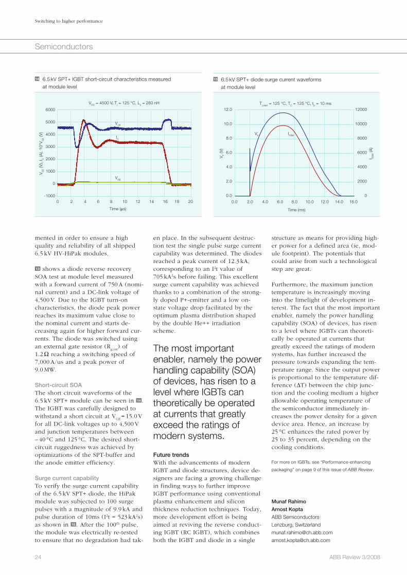
en place. In the subsequent destruc-tion test the single pulse surge current capability was determined. The diodes reached a peak current of 12.3 kA, corresponding to an I2t value of 705 kA2s before failing. This excellent surge current capability was achieved thanks to a combination of the strong-ly doped P+-emitter and a low on-state voltage drop facilitated by the optimum plasma distribution shaped by the double He++ irradiation scheme.
The most important enabler, namely the power handling capability (SOA) of devices, has risen to a level where IGBTs can theoretically be operated at currents that greatly exceed the ratings of modern systems.
Future trendsWith the advancements of modern IGBT and diode structures, device de-signers are facing a growing challenge in finding ways to further improve IGBT performance using conventional plasma enhancement and silicon thickness reduction techniques. Today, more development effort is being aimed at reviving the reverse conduct-ing IGBT (RC IGBT), which combines both the IGBT and diode in a single
mented in order to ensure a high quality and reliability of all shipped 6.5 kV HV-HiPak modules.
13 shows a diode reverse recovery SOA test at module level measured with a forward current of 750 A (nomi-nal current) and a DC-link voltage of 4,500 V. Due to the IGBT turn-on characteristics, the diode peak power reaches its maximum value close to the nominal current and starts de-creasing again for higher forward cur-rents. The diode was switched using an external gate resistor (R
g,on) of
1.2 Ω reaching a switching speed of 7,000 A/us and a peak power of 9.0 MW.
Short-circuit SOAThe short circuit waveforms of the 6.5 kV SPT+ module can be seen in 14 . The IGBT was carefully designed to withstand a short circuit at V
GE = 15.0 V
for all DC-link voltages up to 4,500 V and junction temperatures between – 40 °C and 125 °C. The desired short-circuit ruggedness was achieved by optimizations of the SPT-buffer and the anode emitter efficiency.
Surge current capabilityTo verify the surge current capability of the 6.5 kV SPT+ diode, the HiPak module was subjected to 100 surge pulses with a magnitude of 9.9 kA and pulse duration of 10ms (I2t = 523 kA2s) as shown in 15 . After the 100th pulse, the module was electrically re-tested to ensure that no degradation had tak-
14 6.5 kV SPT+ IGBT short-circuit characteristics measured at module level
6000
5000
4000
3000
2000
1000
0
-1000
VDC = 4500 V, Tj = 125 °C, Ls = 280 nH
Time (μs)
0 2 4 6 8 10 12 14 16 18 20
VGE
VCE
IC
VC
E (V
), I C
(A),
10*V
GE (V
)
15 6.5 kV SPT+ diode surge current waveforms at module level
12.0
10.0
8.0
6.0
4.0
2.0
0.0
12000
10000
8000
6000
4000
2000
0
Tj.start = 125 °C, TC = 125 °C, tp = 10 ms
0.0 2.0 4.0 6.0 8.0 10.0 12.0 14.0 16.0
Time (ms)
VFIFSM
VF
(V)
I FSM (A
)

25ABB Review 3/2008
Drives
An estimated 65 percent of electrical energy is used by electric motors, the workhorse of modern industry. Even though these motors efficiently con-vert electrical energy into mechanical energy, some 20 percent of this is lost by wasteful throttling mechanisms in many industrial processes. Powering the process according to demand sig-nificantly reduces the amount of ener-gy consumed. Even a small reduction
The workhorse and its jockeyCombined with electric motors of any power rating, ABB’s AC drives are winning the race in terms of energy efficiency and process controlPieder Jörg, Panu Virolainen, Roelof Timmer
in motor speed would make a huge difference, and the most effective method of controlling a motor’s speed is through the use of AC drives.
Advances in technology, in particular in the area of power electronics, have resulted in the use of AC drives with motors whose power ratings range from 100 Watts to 100 Megawatts. Because of this wide range, client dis-
cussions nowadays tend to focus more on the functional requirements of their application, many of which are satisfied using a drive’s embedded intelligent controller. These controllers enable a wide range of application-segment-specific solutions, ranging from pump applications to demanding metal rolling mill solutions.

ucts. With its strong background in process automation, ABB has been able to focus particularly on embed-ding specific application control fea-tures. For example, ABB drives not only control speed according to an external reference, but they can relate their actions to the load of the motor. In addition, these drives are able to compensate for elasticity in the me-chanics, dampen oscillations, autono-mously coordinate action with other drives or even supervise auxiliary equipment.
Converting electrical energyAC motor control – or the ability to convert electrical energy into mechan-ical energy – is based on the principle of electromagnetic induction. The voltage in the stator windings forms the current and magnetic flux, and changing the direction of this voltage causes the direction of the flux to also change. If the voltage direction in the windings of a three-phase motor is changed in the correct order, the mag-netic flux of the motor starts to rotate. The motor’s rotor will then follow this rotating flux. This control can be achieved using a frequency converter, which in principle, changes the fre-quency and amplitude of the normally fixed network voltage.
In practice, however, AC motor con-trol is slightly more intricate. Rotor currents, generated by magnetic flux, complicate the situation. Additionally, external interferences, such as tem-perature or load changes, can also create control difficulties. Neverthe-less, with today’s technology and know-how, it is possible to effectively deal with these interferences.
ABB’s modern AC drives are all based on the same basic circuit, the voltage-source inverter. It consists of a rectifi-er, a DC-bus circuit and an inverter unit 2 . The rectifier converts a regular 50 Hz three-phase current into a DC current that is fed into the DC-bus circuit. This circuit then filters out the pulsating voltage, thus establishing a DC voltage. The proceeding inverter unit inverts this voltage into an AC
year [1]. This is equal to the annual output of 144 fossil-fuel-type power plants1), or equivalent to the total energy consumption in Spain.
AC drives are used in a wide range of applications in many industries, such as cement, chemical, pulp and paper, metal, and oil and gas.
With an estimated 16 percent of the global market, ABB is the number one supplier of variable-speed drives 1 . Its drives product portfolio covers all motors with a broad range of embed-ded control functionality and with power ratings from 100 Watts to 100 Megawatts. To enhance its drives even further, ABB engineers have carefully selected key technologies from the academic and industrial field of power electronics. Each technology has been adapted and extended way and above the application requirements. For ex-ample, the power conversion circuit found throughout the product range is based on the so-called voltage-source inverter technology, and the high performance motor control strategy, direct torque control (DTC) is applied to low-voltage induction motors as well as to medium-voltage synchro-nous motors.
Thanks to technological develop-ments, drive manufacturers have been able to add attractive features to in-crease the functionality of their prod-
Electric motors are, quite literally, the driving force behind all auto-
mation systems used in industry, com-merce and buildings. In fact, motors consume around 65 percent of all the electrical energy produced in the world. There are two types of electric motor, AC and DC, and about three-quarters of all motors power pumps, fans or compressors. Industrial pro-cesses tend to use AC motors, particu-larly squirrel cage motors. However, when connected directly to the power grid, an AC motor by design will run at a fixed speed. To regulate the amount of energy consumed, the motor generally requires some kind of variable-speed control.
Variable speed is accomplished by placing the motor under the control of an AC drive, also called a variable-speed drive or an adjustable-speed drive. These drives are used in a wide range of applications in many indus-tries, such as cement, chemical, pulp and paper, metal, and oil and gas. For example, in power plants and in the chemical industry, motors need to be adjusted according to the main pro-cess, which changes due to varying power demands at different times of the day, week or year.
AC drives are ideal in such a case because they follow demand with high efficiency. In fact, they can cut a com-pany’s energy bill by up to 60 percent! According to an ABB study, the use of medium-voltage AC drives in the speed control of pumps, fans and compressors has the potential to deliver global savings of 227 TWh per
26 ABB Review 3/2008
The workhorse and its jockey
Drives
Footnote1) Assuming an average plant produces 350 MW for
4,500 hours/year.
1 For over 40 years, ABB has been at the forefront of drives technology.
Start of AC drive
development
First large power
PWM drive
Size reduction up to factor
of six
Motor-friendly multi-level
drive
Servo performance LV AC drive
First digital vector control
Voltage source drive for
synchronous motor
DTC
ABB – Pioneering drives
1969 1975 1985 1995 19992002
2005
2006
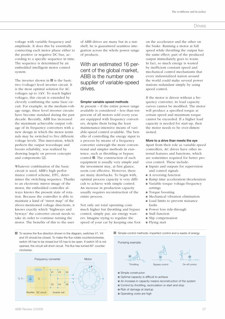
27ABB Review 3/2008
The workhorse and its jockey
Drives
2 To receive the flux direction shown in the diagram, switches V1, V4 and V5 should be closed. To make the flux rotate counterclockwise, switch V6 has to be closed but V5 has to be open. If switch V5 is not opened, the circuit will short circuit. The flux has turned 60° counter-clockwise.
Rectifler
U, 3 ~
+
-
C
V1
V2
V3
V4
V5
V6
DC circuit Inverter unit
Frequency converter Motor
Ψ
3 Simple control methods: imperfect control and a waste of energy
Throttling
Simple construcion Optimal capacity is difficult to achieve An increase in capacity means reconstruction of the system Control by throttling, recirculation or start and stop Risk of damage at startup Operating costs are high
Bypass control On-off control
Pumping example:
M M M
on the accelerator and the other on the brake. Running a motor at full speed while throttling the output has the same effect; part of the produced output immediately goes to waste. In fact, so much energy is wasted by inefficient constant speed and mechanical control mechanisms that every industrialized nation around the world could make several power stations redundant simply by using speed control.
If the motor is driven without a fre-quency converter, its load capacity curves cannot be modified. The motor will produce a specified torque at certain speed and maximum torque cannot be exceeded. If a higher load capacity is needed for start-up, then the motor needs to be over-dimen-sioned.
More to a drive than meets the eyeApart from their role as variable-speed controllers, AC drives have other in-ternal features and functions, which are sometimes required for better pro-cess control. These include: Inputs and outputs for supervision and control signals
A reversing function Ramp time acceleration/deceleration Variable torque voltage/frequency settings
Torque boosting Mechanical vibration elimination Load limits to prevent nuisance faults
Power loss ride-through Stall function Slip compensation Flying start
of ABB drives are many but in a nut-shell, he is guaranteed seamless inte-gration across the whole power range of products.
With an estimated 16 per-cent of the global market, ABB is the number one supplier of variable-speed drives.
Simpler variable speed methodsAt present – if the entire power range available is considered – less than ten percent of all motors sold every year are equipped with frequency convert-ers, despite them being the least maintenance-intensive means of vari-able-speed control available. The ben-efits of controlling the energy input to a process by means of a frequency converter outweigh the more conven-tional and simpler methods in exis-tence, such as throttling or bypass control 3 . The construction of such equipment is usually very simple and the investment may, at first glance, seem cost effective. However, there are many drawbacks. To begin with, optimal process capacity is very diffi-cult to achieve with simple control. An increase in production capacity usually requires reconstruction of the entire process.
Not only are total operating costs much higher but throttling and bypass control, simply put, are energy wast-ers. Imagine trying to regulate the speed of your car by keeping one foot
voltage with variable frequency and amplitude. It does this by essentially connecting each motor phase either to the positive or negative DC bus, ac-cording to a specific sequence in time. The sequence is determined by an embedded intelligent motor control system.
The inverter shown in 2 is the basic two (voltage) level inverter circuit. It is the most optimal solution for AC voltages up to 1 kV. To reach higher voltages, this circuit is extended by cleverly combining the same base cir-cuit. For example, in the medium-volt-age range, three level inverter circuits have become standard during the past decade. Recently, ABB has increased the maximum achievable output volt-age of its frequency converters with a new design in which the motor termi-nals may be switched to five different voltage levels. This innovation, which perfects the output waveshape and boosts reliability, was realized by drawing largely on proven concepts and components [2].
Whatever combination of the basic circuit is used, ABB’s high perfor-mance control scheme, DTC, deter-mines the switching sequence. Thanks to an electronic mirror image of the motor, the embedded controller al-ways knows the present state of rota-tion. Because the controller is able to maintain a kind of “street map” of the above-mentioned voltage directions, it knows exactly which “highways and byways” the converter circuit needs to take in order to continue turning the motor. The benefits of this to the user
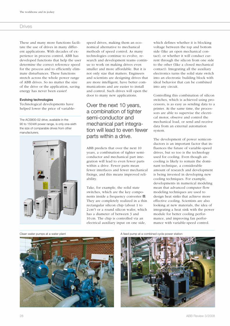
28 ABB Review 3/2008
The workhorse and its jockey
Drives
which defines whether it is blocking voltage between the top and bottom side (like an open mechanical con-tact), or whether it will conduct cur-rent through the silicon from one side to the other (like a closed mechanical contact). Integrating all the auxiliary electronics turns the solid state switch into an electronic building block with ideal behavior that can be combined into any circuit.
Controlling this combination of silicon switches, which is achieved using pro-cessors, is as easy as sending data to a printer. At the same time, the proces-sors are able to supervise the electri-cal motor, observe and control the mechanical load, or send and receive data from an external automation system.
The development of power semicon-ductors is an important factor that in-fluences the future of variable-speed drives, but so too is the technology used for cooling. Even though air-cooling is likely to remain the domi-nant technique, a considerable amount of research and development is being invested in developing new cooling techniques. For example, developments in numerical modeling mean that advanced computer flow modeling techniques are used to design heat sinks that achieve more effective cooling. Scientists are also looking at new materials, the idea of integrating a heat sink with the power module for better cooling perfor-mance, and improving fan perfor-mance with variable-speed control.
speed drives, making them an eco-nomical alternative to mechanical methods of speed control. As many technologies continue to evolve, re-search and development teams contin-ue to work on making drives even smaller and more affordable. But it is not only size that matters. Engineers and scientists are designing drives that are more intelligent, have better com-munications and are easier to install and control. Such drives will open the door to many new applications.
Over the next 10 years, a combination of tighter semi-conductor and mechanical part integra-tion will lead to even fewer parts within a drive.
ABB predicts that over the next 10 years, a combination of tighter semi-conductor and mechanical part inte-gration will lead to even fewer parts within a drive. Fewer parts mean fewer interfaces and fewer mechanical fixings, and this means improved reli-ability.
Take, for example, the solid state switches, which are the key compo-nents inside a frequency converter 2 . They are completely realized in a thin rectangular silicon chip (about 1 to 2 cm2) or a round silicon wafer, which has a diameter of between 3 and 10 cm. The chip is controlled via an electrical auxiliary input on one side,
These and many more functions facili-tate the use of drives in many differ-ent applications. With decades of ex-perience in process control, ABB has developed functions that help the user determine the correct reference speed for the process and to efficiently elim-inate disturbances. These functions stretch across the whole power range of ABB drives. So no matter the size of the drive or the application, saving energy has never been easier!
Evolving technologiesTechnological developments have helped lower the price of variable-
The ACS800-02 drive, available in the 90 to 150 kW power range, is only one-sixth the size of comparable drives from other manufacturers.
Clean water pumps at a water plant A feed pump at a combined cycle power station
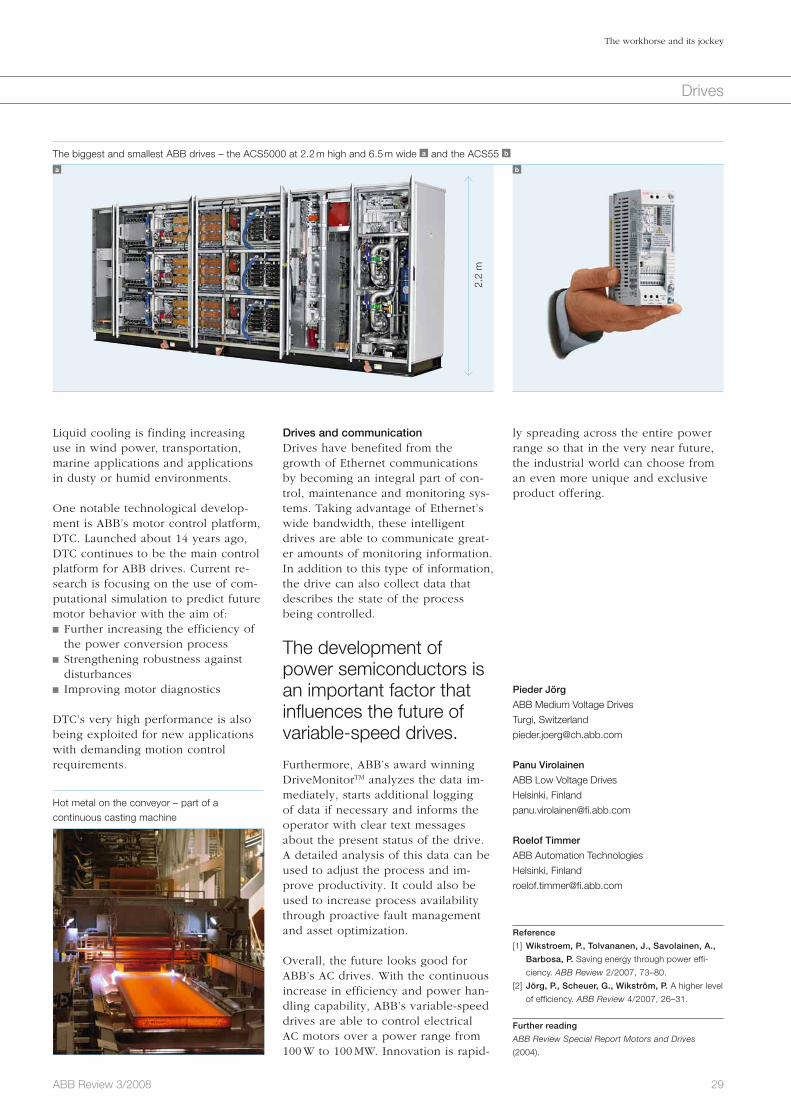
29ABB Review 3/2008
The workhorse and its jockey
Drives
ly spreading across the entire power range so that in the very near future, the industrial world can choose from an even more unique and exclusive product offering.
Pieder Jörg
ABB Medium Voltage Drives
Turgi, Switzerland
Panu Virolainen
ABB Low Voltage Drives
Helsinki, Finland
Roelof Timmer
ABB Automation Technologies
Helsinki, Finland
Reference
[1] Wikstroem, P., Tolvananen, J., Savolainen, A.,
Barbosa, P. Saving energy through power effi-
ciency. ABB Review 2/2007, 73–80.
[2] Jörg, P., Scheuer, G., Wikström, P. A higher level
of efficiency. ABB Review 4/2007, 26–31.
Further reading
ABB Review Special Report Motors and Drives
(2004).
Drives and communicationDrives have benefited from the growth of Ethernet communications by becoming an integral part of con-trol, maintenance and monitoring sys-tems. Taking advantage of Ethernet’s wide bandwidth, these intelligent drives are able to communicate great-er amounts of monitoring information. In addition to this type of information, the drive can also collect data that describes the state of the process being controlled.
The development of power semiconductors is an important factor that influences the future of variable-speed drives.
Furthermore, ABB’s award winning DriveMonitorTM analyzes the data im-mediately, starts additional logging of data if necessary and informs the operator with clear text messages about the present status of the drive. A detailed analysis of this data can be used to adjust the process and im-prove productivity. It could also be used to increase process availability through proactive fault management and asset optimization.
Overall, the future looks good for ABB’s AC drives. With the continuous increase in efficiency and power han-dling capability, ABB’s variable-speed drives are able to control electrical AC motors over a power range from 100 W to 100 MW. Innovation is rapid-
Liquid cooling is finding increasing use in wind power, transportation, marine applications and applications in dusty or humid environments.
One notable technological develop-ment is ABB’s motor control platform, DTC. Launched about 14 years ago, DTC continues to be the main control platform for ABB drives. Current re-search is focusing on the use of com-putational simulation to predict future motor behavior with the aim of: Further increasing the efficiency of the power conversion process
Strengthening robustness against disturbances
Improving motor diagnostics
DTC’s very high performance is also being exploited for new applications with demanding motion control requirements.
The biggest and smallest ABB drives – the ACS5000 at 2.2 m high and 6.5 m wide a and the ACS55 b
a b
Hot metal on the conveyor – part of a continuous casting machine
2.2
m

30 ABB Review 3/2008
Drives
Drives represent a huge chance for energy savings. Especially in variable-speed applications, considerable sav-ings can be obtained when a drive is adopted. The drive supplies the volt-age and current to the motor that is needed to take it to the required speed. This is much more efficient than the traditional way of running the motor at a constant speed and using dampers or similar elements to throt-tle flow.
However, the savings often become apparent only during the lifetime of the equipment, and many customers
A team of drivesMultidrives with active front-end technology in the cement and minerals industryRolf Hoppler, Urs Maier, Daniel Ryf, Leopold Blahous
prefer not to adopt the technology due to higher initial costs. So how can one cut these costs?
ABB’s response is multidrives. Nor-mally, every drive has a rectifier and an inverter. The rectifier converts the AC from the net to DC, which the i nverter then converts to AC of the required frequency and voltage. Obviously, every motor needs its own inverter to permit it to be controlled individually. But the rectifiers can be combined into a single larger unit. This is the basic concept of a Multidrive.
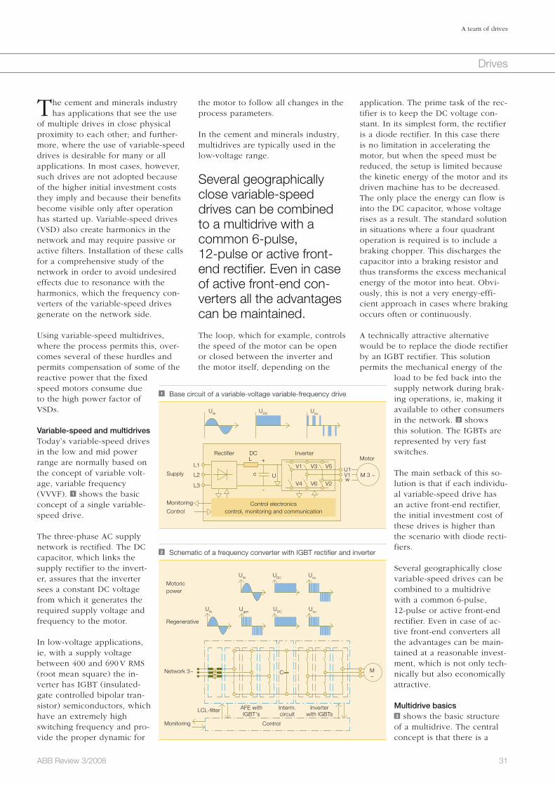
application. The prime task of the rec-tifier is to keep the DC voltage con-stant. In its simplest form, the rectifier is a diode rectifier. In this case there is no limitation in accelerating the motor, but when the speed must be reduced, the setup is limited because the kinetic energy of the motor and its driven machine has to be decreased. The only place the energy can flow is into the DC capacitor, whose voltage rises as a result. The standard solution in situations where a four quadrant operation is required is to include a braking chopper. This discharges the capacitor into a braking resistor and thus transforms the excess mechanical energy of the motor into heat. Obvi-ously, this is not a very energy-effi-cient approach in cases where braking occurs often or continuously.
A technically attractive alternative would be to replace the diode rectifier by an IGBT rectifier. This solution permits the mechanical energy of the
load to be fed back into the supply network during brak-ing operations, ie, making it available to other consumers in the network. 2 shows this solution. The IGBTs are represented by very fast switches.
The main setback of this so-lution is that if each individu-al variable-speed drive has an active front-end rectifier, the initial investment cost of these drives is higher than the scenario with diode recti-fiers.
Several geographically close variable-speed drives can be combined to a multidrive with a common 6-pulse, 12-pulse or active front-end rectifier. Even in case of ac-tive front-end converters all the advantages can be main-tained at a reasonable invest-ment, which is not only tech-nically but also economically attractive.
Multidrive basics3 shows the basic structure of a multidrive. The central concept is that there is a
the motor to follow all changes in the process parameters.
In the cement and minerals industry, multidrives are typically used in the low-voltage range.
Several geographically close variable-speed drives can be combined to a multidrive with a common 6-pulse, 12-pulse or active front-end rectifier. Even in case of active front-end con-verters all the advantages can be maintained.
The loop, which for example, controls the speed of the motor can be open or closed between the inverter and the motor itself, depending on the
The cement and minerals industry has applications that see the use
of multiple drives in close physical proximity to each other; and further-more, where the use of variable-speed drives is desirable for many or all applications. In most cases, however, such drives are not adopted because of the higher initial investment costs they imply and because their benefits become visible only after operation has started up. Variable-speed drives (VSD) also create harmonics in the network and may require passive or active filters. Installation of these calls for a comprehensive study of the network in order to avoid undesired effects due to resonance with the harmonics, which the frequency con-verters of the variable-speed drives generate on the network side.
Using variable-speed multidrives, where the process permits this, over-comes several of these hurdles and permits compensation of some of the reactive power that the fixed speed motors consume due to the high power factor of VSDs.
Variable-speed and multidrivesToday’s variable-speed drives in the low and mid power range are normally based on the concept of variable volt-age, variable frequency (VVVF). 1 shows the basic concept of a single variable-speed drive.
The three-phase AC supply network is rectified. The DC capacitor, which links the supply rectifier to the invert-er, assures that the inverter sees a constant DC voltage from which it generates the required supply voltage and frequency to the motor.
In low-voltage applications, ie, with a supply voltage between 400 and 690 V RMS (root mean square) the in-verter has IGBT (insulated- gate controlled bipolar tran-sistor) semiconductors, which have an extremely high switching frequency and pro-vide the proper dynamic for
31ABB Review 3/2008
A team of drives
Drives
1 Base circuit of a variable-voltage variable-frequency drive
Monitoring
Supply
MotorInverterDC
c U
V1 V3 V5U1V1 M 3 ~w
V4 V6 V2
Rectifier
L1
Ulin UDC Uou
L +
-
L2
L3
ControlControl electronics
control, monitoring and communication
2 Schematic of a frequency converter with IGBT rectifier and inverter
Motoric power
Regenerative
Network 3~
Monitoring Control
LCL-filter AFE with IGBT's
Interm. circuit
Inverter with IGBTs
M ~
UouUDC
UDCUgenUlin Uou
Ulin
C
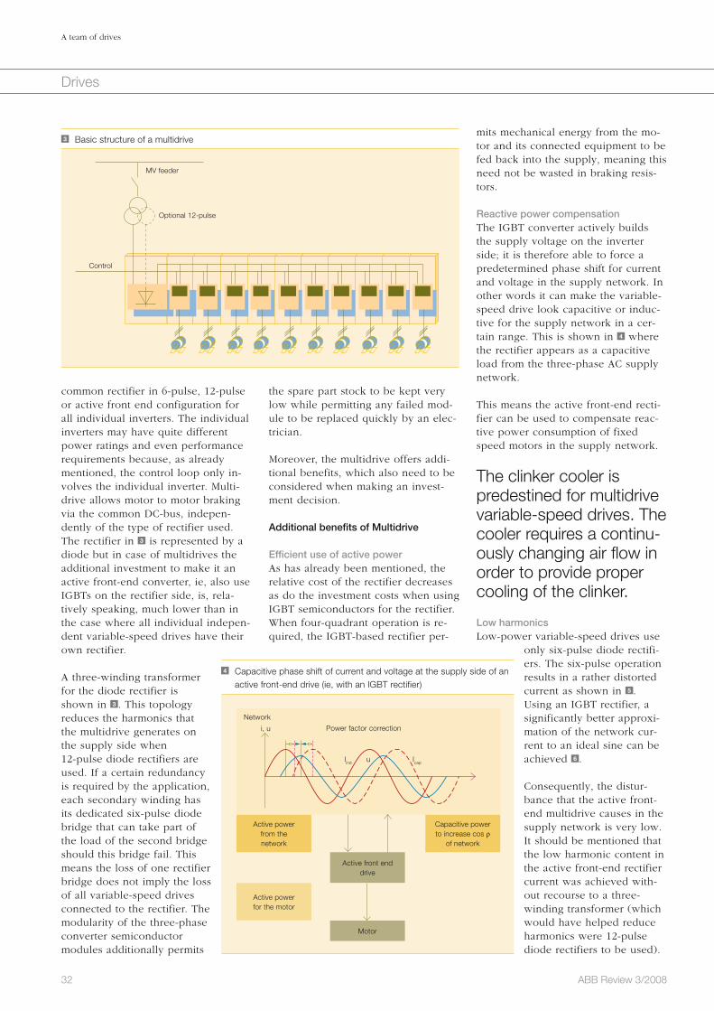
32 ABB Review 3/2008
A team of drives
Drives
mits mechanical energy from the mo-tor and its connected equipment to be fed back into the supply, meaning this need not be wasted in braking resis-tors.
Reactive power compensation The IGBT converter actively builds the supply voltage on the inverter side; it is therefore able to force a predetermined phase shift for current and voltage in the supply network. In other words it can make the variable-speed drive look capacitive or induc-tive for the supply network in a cer-tain range. This is shown in 4 where the rectifier appears as a capacitive load from the three-phase AC supply network.
This means the active front-end recti-fier can be used to compensate reac-tive power consumption of fixed speed motors in the supply network.
The clinker cooler is predestined for multidrive variable-speed drives. The cooler requires a continu-ously changing air flow in order to provide proper cooling of the clinker.
Low harmonicsLow-power variable-speed drives use
only six-pulse diode rectifi-ers. The six-pulse operation results in a rather distorted current as shown in 5 . Using an IGBT rectifier, a significantly better approxi-mation of the network cur-rent to an ideal sine can be achieved 6 .
Consequently, the distur-bance that the active front-end multidrive causes in the supply network is very low. It should be mentioned that the low harmonic content in the active front-end rectifier current was achieved with-out recourse to a three-winding transformer (which would have helped reduce harmonics were 12-pulse diode rectifiers to be used).
the spare part stock to be kept very low while permitting any failed mod-ule to be replaced quickly by an elec-trician.
Moreover, the multidrive offers addi-tional benefits, which also need to be considered when making an invest-ment decision.
Additional benefits of Multidrive
Efficient use of active powerAs has already been mentioned, the relative cost of the rectifier decreases as do the investment costs when using IGBT semiconductors for the rectifier. When four-quadrant operation is re-quired, the IGBT-based rectifier per-
common rectifier in 6-pulse, 12-pulse or active front end configuration for all individual inverters. The individual inverters may have quite different power ratings and even performance requirements because, as already mentioned, the control loop only in-volves the individual inverter. Multi-drive allows motor to motor braking via the common DC-bus, indepen-dently of the type of rectifier used. The rectifier in 3 is represented by a diode but in case of multidrives the additional investment to make it an active front-end converter, ie, also use IGBTs on the rectifier side, is, rela-tively speaking, much lower than in the case where all individual indepen-dent variable-speed drives have their own rectifier.
A three-winding transformer for the diode rectifier is shown in 3 . This topology reduces the harmonics that the multidrive generates on the supply side when 12-pulse diode rectifiers are used. If a certain redundancy is required by the application, each secondary winding has its dedicated six-pulse diode bridge that can take part of the load of the second bridge should this bridge fail. This means the loss of one rectifier bridge does not imply the loss of all variable-speed drives connected to the rectifier. The modularity of the three-phase converter semiconductor modules additionally permits
4 Capacitive phase shift of current and voltage at the supply side of an active front-end drive (ie, with an IGBT rectifier)
Network
Power factor correction
Active powerfrom thenetwork
Active powerfor the motor
Capacitive powerto increase cos ρ
of network
Active front end drive
Motor
i, u
uIind Icap
3 Basic structure of a multidrive
MV feeder
Control
Optional 12-pulse
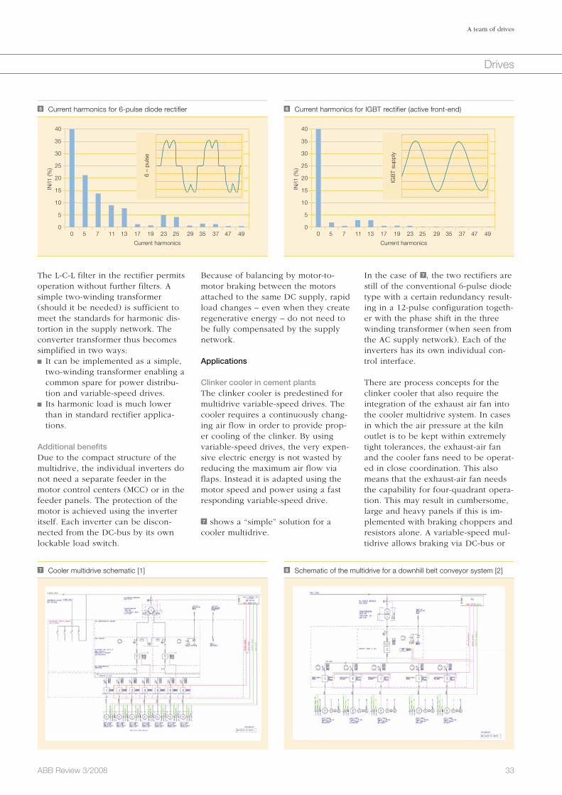
33ABB Review 3/2008
A team of drives
Drives
In the case of 7 , the two rectifiers are still of the conventional 6-pulse diode type with a certain redundancy result-ing in a 12-pulse configuration togeth-er with the phase shift in the three winding transformer (when seen from the AC supply network). Each of the inverters has its own individual con-trol interface.
There are process concepts for the clinker cooler that also require the integration of the exhaust air fan into the cooler multidrive system. In cases in which the air pressure at the kiln outlet is to be kept within extremely tight tolerances, the exhaust-air fan and the cooler fans need to be operat-ed in close coordination. This also means that the exhaust-air fan needs the capability for four-quadrant opera-tion. This may result in cumbersome, large and heavy panels if this is im-plemented with braking choppers and resistors alone. A variable-speed mul-tidrive allows braking via DC-bus or
Because of balancing by motor-to- motor braking between the motors attached to the same DC supply, rapid load changes – even when they create regenerative energy – do not need to be fully compensated by the supply network.
Applications
Clinker cooler in cement plantsThe clinker cooler is predestined for multidrive variable-speed drives. The cooler requires a continuously chang-ing air flow in order to provide prop-er cooling of the clinker. By using variable-speed drives, the very expen-sive electric energy is not wasted by reducing the maximum air flow via flaps. Instead it is adapted using the motor speed and power using a fast responding variable-speed drive.
7 shows a “simple” solution for a cooler multidrive.
The L-C-L filter in the rectifier permits operation without further filters. A simple two-winding transformer (should it be needed) is sufficient to meet the standards for harmonic dis-tortion in the supply network. The converter transformer thus becomes simplified in two ways: It can be implemented as a simple, two-winding transformer enabling a common spare for power distribu-tion and variable-speed drives.
Its harmonic load is much lower than in standard rectifier applica-tions.
Additional benefitsDue to the compact structure of the multidrive, the individual inverters do not need a separate feeder in the motor control centers (MCC) or in the feeder panels. The protection of the motor is achieved using the inverter itself. Each inverter can be discon-nected from the DC-bus by its own lockable load switch.
5 Current harmonics for 6-pulse diode rectifier
0 5 7 11 13 17 19 23 25 29 35 37 47 49
40
35
30
25
20
15
10
5
0
IN/I1
(%)
Current harmonics
6 –
puls
e
6 Current harmonics for IGBT rectifier (active front-end)
0 5 7 11 13 17 19 23 25 29 35 37 47 49
40
35
30
25
20
15
10
5
0
IN/I1
(%)
Current harmonics
IGB
T su
pply
7 Cooler multidrive schematic [1] 8 Schematic of the multidrive for a downhill belt conveyor system [2]
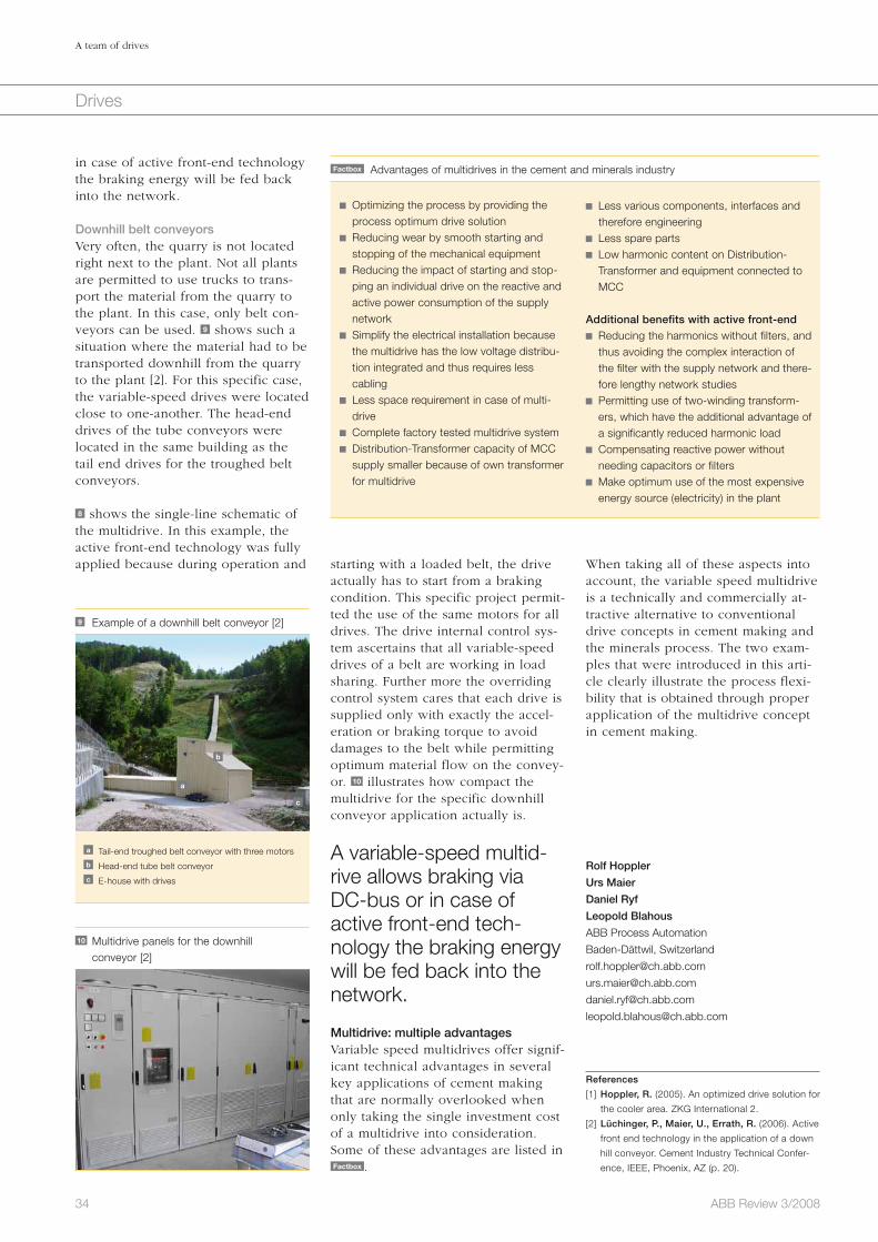
34 ABB Review 3/2008
A team of drives
Drives
When taking all of these aspects into account, the variable speed multidrive is a technically and commercially at-tractive alternative to conventional drive concepts in cement making and the minerals process. The two exam-ples that were introduced in this arti-cle clearly illustrate the process flexi-bility that is obtained through proper application of the multidrive concept in cement making.
Rolf Hoppler
Urs Maier
Daniel Ryf
Leopold Blahous
ABB Process Automation
Baden-Dättwil, Switzerland
References
[1] Hoppler, R. (2005). An optimized drive solution for
the cooler area. ZKG International 2.
[2] Lüchinger, P., Maier, U., Errath, R. (2006). Active
front end technology in the application of a down
hill conveyor. Cement Industry Technical Confer-
ence, IEEE, Phoenix, AZ (p. 20).
starting with a loaded belt, the drive actually has to start from a braking condition. This specific project permit-ted the use of the same motors for all drives. The drive internal control sys-tem ascertains that all variable-speed drives of a belt are working in load sharing. Further more the overriding control system cares that each drive is supplied only with exactly the accel-eration or braking torque to avoid damages to the belt while permitting optimum material flow on the convey-or. 10 illustrates how compact the multidrive for the specific downhill conveyor application actually is.
A variable-speed multid-rive allows braking via DC-bus or in case of active front-end tech-nology the braking energy will be fed back into the network.
Multidrive: multiple advantagesVariable speed multidrives offer signif-icant technical advantages in several key applications of cement making that are normally overlooked when only taking the single investment cost of a multidrive into consideration. Some of these advantages are listed in Factbox .
in case of active front-end technology the braking energy will be fed back into the network.
Downhill belt conveyorsVery often, the quarry is not located right next to the plant. Not all plants are permitted to use trucks to trans-port the material from the quarry to the plant. In this case, only belt con-veyors can be used. 9 shows such a situation where the material had to be transported downhill from the quarry to the plant [2]. For this specific case, the variable-speed drives were located close to one-another. The head-end drives of the tube conveyors were located in the same building as the tail end drives for the troughed belt conveyors.
8 shows the single-line schematic of the multidrive. In this example, the active front-end technology was fully applied because during operation and
10 Multidrive panels for the downhill conveyor [2]
9 Example of a downhill belt conveyor [2]
a Tail-end troughed belt conveyor with three motorsb Head-end tube belt conveyorc E-house with drives
a
b
c
Factbox Advantages of multidrives in the cement and minerals industry
Optimizing the process by providing the process optimum drive solution
Reducing wear by smooth starting and stopping of the mechanical equipment
Reducing the impact of starting and stop-ping an individual drive on the reactive and active power consumption of the supply network
Simplify the electrical installation because the multidrive has the low voltage distribu-tion integrated and thus requires less cabling
Less space requirement in case of multi-drive
Complete factory tested multidrive system Distribution-Transformer capacity of MCC supply smaller because of own transformer for multidrive
Less various components, interfaces and therefore engineering
Less spare parts Low harmonic content on Distribution-Transformer and equipment connected to MCC
Additional benefits with active front-end
Reducing the harmonics without filters, and thus avoiding the complex interaction of the filter with the supply network and there-fore lengthy network studies
Permitting use of two-winding transform-ers, which have the additional advantage of a significantly reduced harmonic load
Compensating reactive power without needing capacitors or filters
Make optimum use of the most expensive energy source (electricity) in the plant

35ABB Review 3/2008
Converters
We are surrounded by electronic devices of all types and descriptions, and expect these to perform autonomously and correctly. In power electronics, the demands on such devices are especially tough. The time domain, which must be handled, ranges from nanoseconds for the triggering and monitoring of the individual switching actions to seconds for long-term operational transients. Designing a single, slim and efficient controller to handle all this is no easy task.
ABB’s AC 800PEC controller was designed specifically with such applications in mind. The model can flexibly be adapted to handle different time domains and code can efficiently be created from Matlab/SimulinkTM models.
The processing unit inside the early AC 800PEC controllers was the PP D103. However, specifi-cally targeting smaller systems where both space and costs are critical, ABB has produced a new controller based on the PP D104 processor – an ultra-compact device taking up less space than a credit card.
The compact controllerPP D104: A low-end extension to the AC 800PEC Control Platform Beat Schaerz, Michael Bueckel, Peter Steimer
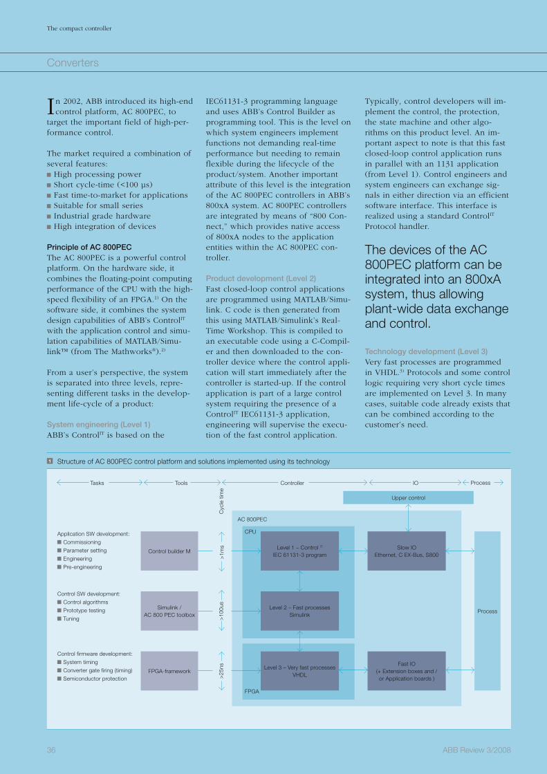
36 ABB Review 3/2008
The compact controller
Converters
Typically, control developers will im-plement the control, the protection, the state machine and other algo-rithms on this product level. An im-portant aspect to note is that this fast closed-loop control application runs in parallel with an 1131 application (from Level 1). Control engineers and system engineers can exchange sig-nals in either direction via an efficient software interface. This interface is realized using a standard ControlIT Protocol handler.
The devices of the AC 800PEC platform can be integrated into an 800xA system, thus allowing plant-wide data exchange and control.
Technology development (Level 3) Very fast processes are programmed in VHDL.3) Protocols and some control logic requiring very short cycle times are implemented on Level 3. In many cases, suitable code already exists that can be combined according to the customer’s need.
IEC61131-3 programming language and uses ABB’s Control Builder as programming tool. This is the level on which system engineers implement functions not demanding real-time performance but needing to remain flexible during the lifecycle of the product/system. Another important attribute of this level is the integration of the AC 800PEC controllers in ABB’s 800xA system. AC 800PEC controllers are integrated by means of “800 Con-nect,” which provides native access of 800xA nodes to the application entities within the AC 800PEC con-troller. Product development (Level 2) Fast closed-loop control applications are programmed using MATLAB/Simu-link. C code is then generated from this using MATLAB/Simulink’s Real-Time Workshop. This is compiled to an executable code using a C-Compil-er and then downloaded to the con-troller device where the control appli-cation will start immediately after the controller is started-up. If the control application is part of a large control system requiring the presence of a ControlIT IEC61131-3 application, engineering will supervise the execu-tion of the fast control application.
In 2002, ABB introduced its high-end control platform, AC 800PEC, to
target the important field of high-per-formance control.
The market required a combination of several features: High processing power Short cycle-time (<100 µs) Fast time-to-market for applications Suitable for small series Industrial grade hardware High integration of devices
Principle of AC 800PECThe AC 800PEC is a powerful control platform. On the hardware side, it combines the floating-point computing performance of the CPU with the high-speed flexibility of an FPGA.1) On the software side, it combines the system design capabilities of ABB’s ControlIT with the application control and simu-lation capabilities of MATLAB/Simu-link™ (from The Mathworks®).2)
From a user’s perspective, the system is separated into three levels, repre-senting different tasks in the develop-ment life-cycle of a product:
System engineering (Level 1) ABB’s ControlIT is based on the
1 Structure of AC 800PEC control platform and solutions implemented using its technology
Tasks
Application SW development:
Commissioning
Parameter setting
Engineering
Pre-engineering
Control SW development:
Control algorithms
Prototype testing
Tuning
Control firmware development:
System timing
Converter gate firing (timing)
Semiconductor protection
AC 800PEC
CPU
FPGA
Tools Controller IO
Upper control
Control builder MLevel 1 – Control IT
IEC 61131-3 programSlow IO
Ethernet, C EX-Bus, S800
Process
Fast IO(+ Extension boxes and /or Application boards )
Level 2 – Fast processesSimulink
Level 3 – Very fast processesVHDL
Simulink /AC 800 PEC toolbox
FPGA-framework
Process
>1m
sC
ycle
tim
e>
25ns
>10
0us
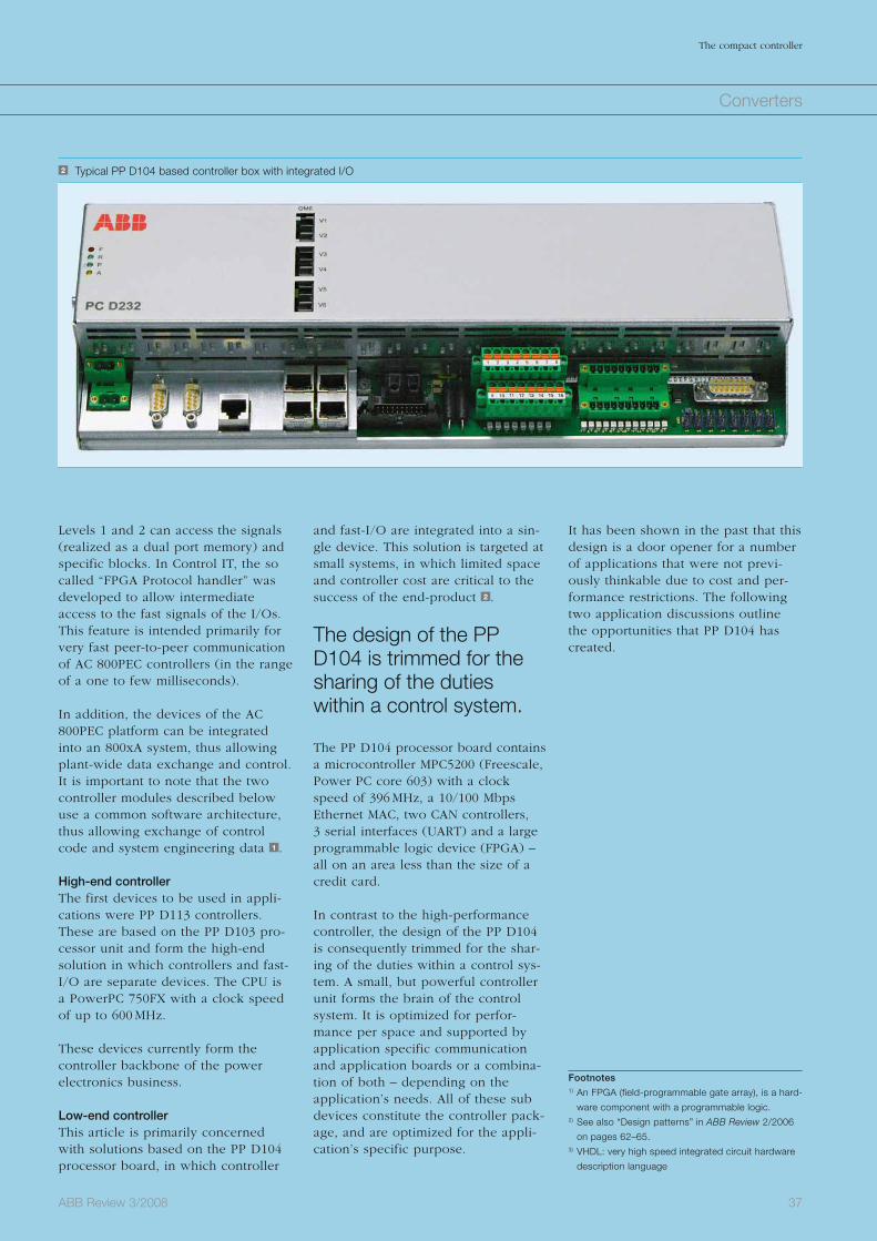
37ABB Review 3/2008
The compact controller
Converters
It has been shown in the past that this design is a door opener for a number of applications that were not previ-ously thinkable due to cost and per-formance restrictions. The following two application discussions outline the opportunities that PP D104 has created.
and fast-I/O are integrated into a sin-gle device. This solution is targeted at small systems, in which limited space and controller cost are critical to the success of the end-product 2 .
The design of the PP D104 is trimmed for the sharing of the duties within a control system.
The PP D104 processor board contains a microcontroller MPC5200 (Freescale, Power PC core 603) with a clock speed of 396 MHz, a 10/100 Mbps Ethernet MAC, two CAN controllers, 3 serial interfaces (UART) and a large programmable logic device (FPGA) – all on an area less than the size of a credit card.
In contrast to the high-performance controller, the design of the PP D104 is consequently trimmed for the shar-ing of the duties within a control sys-tem. A small, but powerful controller unit forms the brain of the control system. It is optimized for perfor-mance per space and supported by application specific communication and application boards or a combina-tion of both – depending on the application’s needs. All of these sub devices constitute the controller pack-age, and are optimized for the appli-cation’s specific purpose.
Levels 1 and 2 can access the signals (realized as a dual port memory) and specific blocks. In Control IT, the so called “FPGA Protocol handler” was developed to allow intermediate access to the fast signals of the I/Os. This feature is intended primarily for very fast peer-to-peer communication of AC 800PEC controllers (in the range of a one to few milliseconds).
In addition, the devices of the AC 800PEC platform can be integrated into an 800xA system, thus allowing plant-wide data exchange and control. It is important to note that the two controller modules described below use a common software architecture, thus allowing exchange of control code and system engineering data 1 .
High-end controllerThe first devices to be used in appli-cations were PP D113 controllers. These are based on the PP D103 pro-cessor unit and form the high-end solution in which controllers and fast-I/O are separate devices. The CPU is a PowerPC 750FX with a clock speed of up to 600 MHz.
These devices currently form the controller backbone of the power electronics business.
Low-end controllerThis article is primarily concerned with solutions based on the PP D104 processor board, in which controller
2 Typical PP D104 based controller box with integrated I/O
Footnotes1) An FPGA (field-programmable gate array), is a hard-
ware component with a programmable logic. 2) See also “Design patterns” in ABB Review 2/2006
on pages 62–65.3) VHDL: very high speed integrated circuit hardware
description language
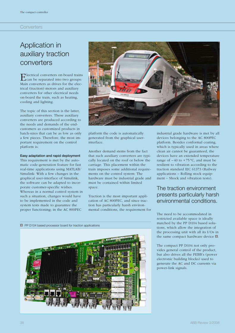
38 ABB Review 3/2008
The compact controller
industrial grade hardware is met by all devices belonging to the AC 800PEC platform. Besides conformal coating, which is typically used in areas where clean air cannot be guaranteed, the devices have an extended temperature range of – 40 to + 75 °C, and must be resilient to vibration according to the traction standard IEC 61373 (Railway applications – Rolling stock equip-ment – Shock and vibration tests).
The traction environment presents particularly harsh environmental conditions.
The need to be accommodated in restricted available space is ideally matched by the PP D104 based solu-tions, which allow the integration of the processing unit with all its I/Os in the same compact hardware device 3 .
The compact PP D104 not only pro-vides general control of the product, but also drives all the PEBB’s (power electronic building blocks) used to generate the AC and DC currents via power-link signals.
platform the code is automatically generated from the graphical user-inter face.
Another demand stems from the fact that such auxiliary converters are typi-cally located on the roof or below the carriage. This placement within the train imposes some additional require-ments on the control system: The hardware must be industrial grade and must be contained within limited space.
Traction is the most important appli-cation of AC 800PEC, and since trac-tion has particularly harsh environ-mental conditions, the requirement for
Application in auxiliary traction converters
Electrical converters on-board trains can be separated into two groups:
Main converters as drives for the elec-trical (traction) motors and auxiliary converters for other electrical needs on-board the train, such as heating, cooling and lighting.
The topic of this section is the latter, auxiliary converters. These auxiliary converters are produced according to the needs and demands of the end-customers as customized products in batch-sizes that can be as low as only a few pieces. Therefore, the most im-portant requirement on the control platform is:
Easy adaptation and rapid deploymentThis requirement is met by the auto-matic code-generation feature for fast real-time applications using MATLAB/Simulink: With a few changes in the graphical user-interface of Simulink, the software can be adapted to incor-porate customer-specific wishes. Whereas in a normal control system in such a situation, changes would have to be implemented in the code and system tests made to guarantee the proper functioning; in the AC 800PEC
3 PP D104 based processor board for traction applications
Converters
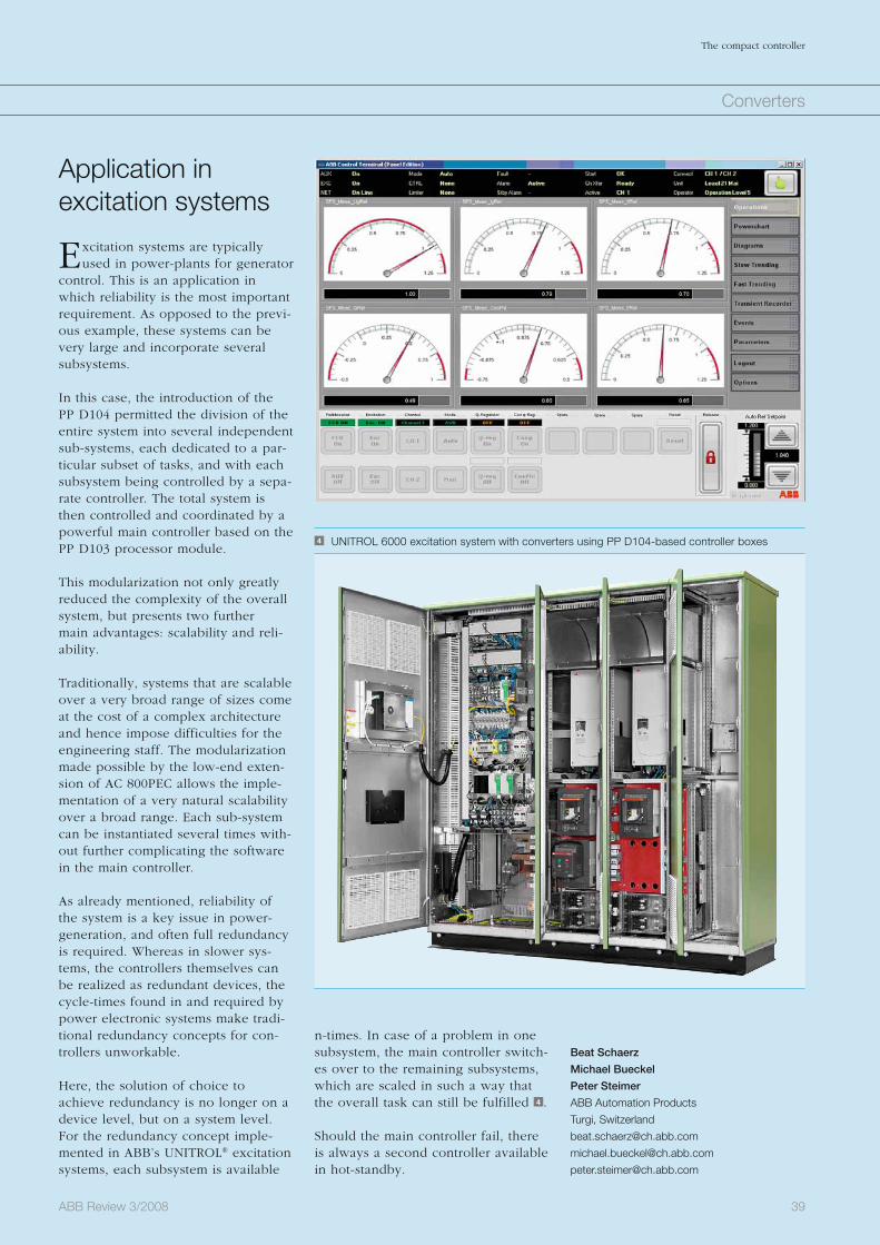
39ABB Review 3/2008
The compact controller
Application in excitation systems
Excitation systems are typically used in power-plants for generator
control. This is an application in which reliability is the most important requirement. As opposed to the previ-ous example, these systems can be very large and incorporate several subsystems.
In this case, the introduction of the PP D104 permitted the division of the entire system into several independent sub-systems, each dedicated to a par-ticular subset of tasks, and with each subsystem being controlled by a sepa-rate controller. The total system is then controlled and coordinated by a powerful main controller based on the PP D103 processor module.
This modularization not only greatly reduced the complexity of the overall system, but presents two further main advantages: scalability and reli-ability.
Traditionally, systems that are scalable over a very broad range of sizes come at the cost of a complex architecture and hence impose difficulties for the engineering staff. The modularization made possible by the low-end exten-sion of AC 800PEC allows the imple-mentation of a very natural scalability over a broad range. Each sub-system can be instantiated several times with-out further complicating the software in the main controller.
As already mentioned, reliability of the system is a key issue in power-generation, and often full redundancy is required. Whereas in slower sys-tems, the controllers themselves can be realized as redundant devices, the cycle-times found in and required by power electronic systems make tradi-tional redundancy concepts for con-trollers unworkable.
Here, the solution of choice to achieve redundancy is no longer on a device level, but on a system level. For the redundancy concept imple-mented in ABB’s UNITROL® excitation systems, each subsystem is available
n-times. In case of a problem in one subsystem, the main controller switch-es over to the remaining subsystems, which are scaled in such a way that the overall task can still be fulfilled 4 .
Should the main controller fail, there is always a second controller available in hot-standby.
Beat Schaerz
Michael Bueckel
Peter Steimer
ABB Automation Products
Turgi, Switzerland
4 UNITROL 6000 excitation system with converters using PP D104-based controller boxes
Converters
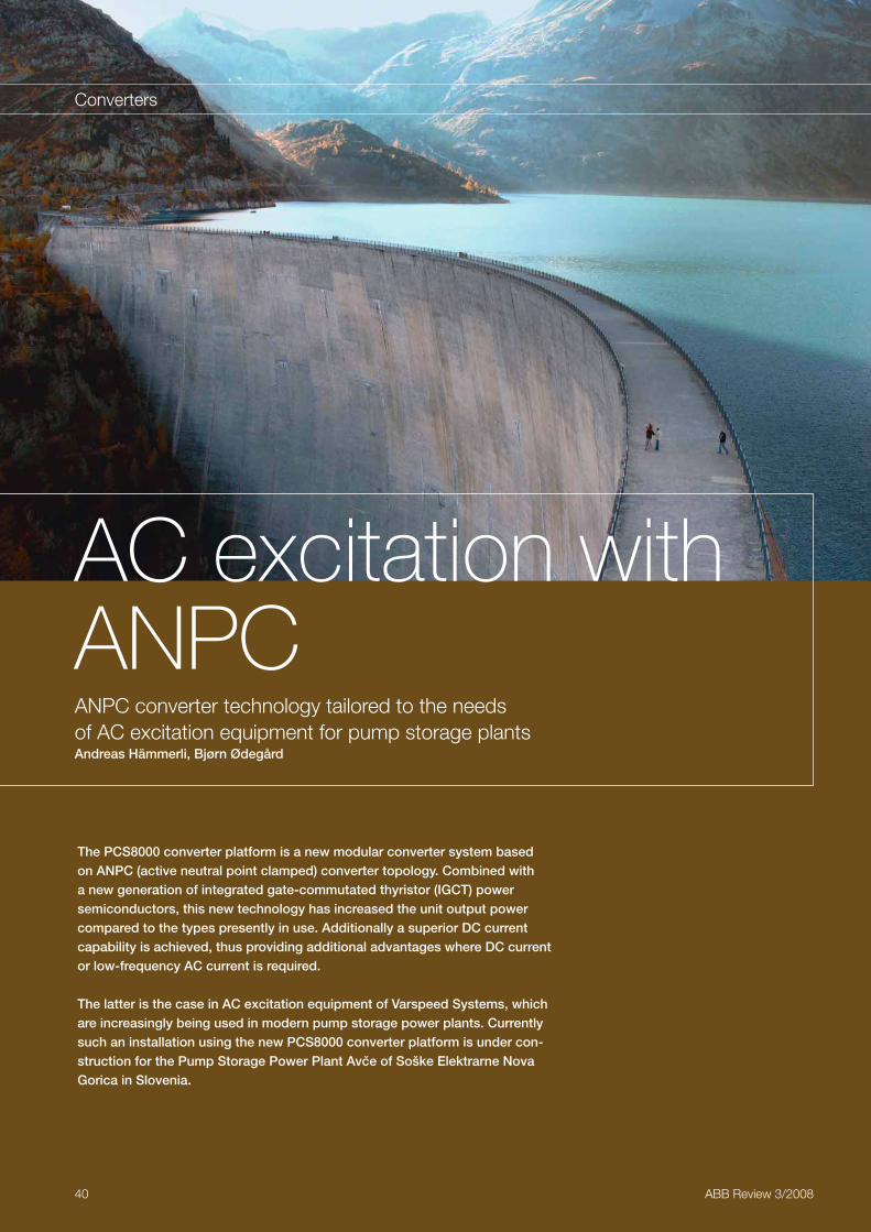
40 ABB Review 3/2008
Converters
The PCS8000 converter platform is a new modular converter system based on ANPC (active neutral point clamped) converter topology. Combined with a new generation of integrated gate-commutated thyristor (IGCT) power semiconductors, this new technology has increased the unit output power compared to the types presently in use. Additionally a superior DC current capability is achieved, thus providing additional advantages where DC current or low-frequency AC current is required.
The latter is the case in AC excitation equipment of Varspeed Systems, which are increasingly being used in modern pump storage power plants. Currently such an installation using the new PCS8000 converter platform is under con-struction for the Pump Storage Power Plant Avce of Soške Elektrarne Nova Gorica in Slovenia.
AC excitation with ANPCANPC converter technology tailored to the needs of AC excitation equipment for pump storage plantsAndreas Hämmerli, Bjørn Ødegård
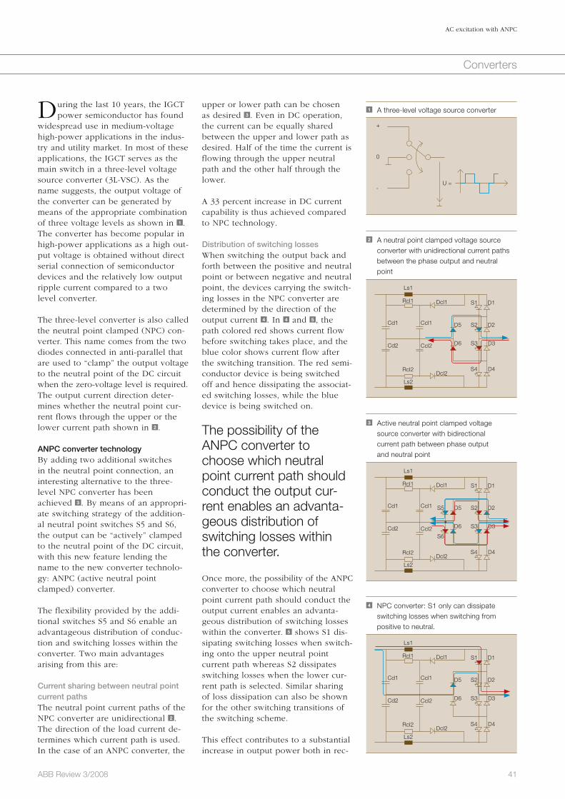
41ABB Review 3/2008
AC excitation with ANPC
Converters
upper or lower path can be chosen as desired 3 . Even in DC operation, the current can be equally shared between the upper and lower path as desired. Half of the time the current is flowing through the upper neutral path and the other half through the lower.
A 33 percent increase in DC current capability is thus achieved compared to NPC technology.
Distribution of switching lossesWhen switching the output back and forth between the positive and neutral point or between negative and neutral point, the devices carrying the switch-ing losses in the NPC converter are determined by the direction of the output current 4 . In 4 and 5 , the path colored red shows current flow before switching takes place, and the blue color shows current flow after the switching transition. The red semi-conductor device is being switched off and hence dissipating the associat-ed switching losses, while the blue device is being switched on.
The possibility of the ANPC converter to choose which neutral point current path should conduct the output cur-rent enables an advanta-geous distribution of switching losses within the converter.
Once more, the possibility of the ANPC converter to choose which neutral point current path should conduct the output current enables an advanta-geous distribution of switching losses within the converter. 5 shows S1 dis-sipating switching losses when switch-ing onto the upper neutral point current path whereas S2 dissipates switching losses when the lower cur-rent path is selected. Similar sharing of loss dissipation can also be shown for the other switching transitions of the switching scheme.
This effect contributes to a substantial increase in output power both in rec-
During the last 10 years, the IGCT power semiconductor has found
widespread use in medium-voltage high-power applications in the indus-try and utility market. In most of these applications, the IGCT serves as the main switch in a three-level voltage source converter (3L-VSC). As the name suggests, the output voltage of the converter can be generated by means of the appropriate combination of three voltage levels as shown in 1 . The converter has become popular in high-power applications as a high out-put voltage is obtained without direct serial connection of semiconductor devices and the relatively low output ripple current compared to a two level converter.
The three-level converter is also called the neutral point clamped (NPC) con-verter. This name comes from the two diodes connected in anti-parallel that are used to “clamp” the output voltage to the neutral point of the DC circuit when the zero-voltage level is required. The output current direction deter-mines whether the neutral point cur-rent flows through the upper or the lower current path shown in 2 .
ANPC converter technologyBy adding two additional switches in the neutral point connection, an interesting alternative to the three-level NPC converter has been achieved 3 . By means of an appropri-ate switching strategy of the addition-al neutral point switches S5 and S6, the output can be “actively” clamped to the neutral point of the DC circuit, with this new feature lending the name to the new converter technolo-gy: ANPC (active neutral point clamped) converter.
The flexibility provided by the addi-tional switches S5 and S6 enable an advantageous distribution of conduc-tion and switching losses within the converter. Two main advantages arising from this are:
Current sharing between neutral point current pathsThe neutral point current paths of the NPC converter are unidirectional 2 . The direction of the load current de-termines which current path is used. In the case of an ANPC converter, the
1 A three-level voltage source converter
+
U =
0
-
2 A neutral point clamped voltage source converter with unidirectional current paths between the phase output and neutral point
Cd1 Ccl1
Ccl2 D6
D5 S2
S1
D2
D1
S3 D3
D4S4
Ls1
Rcl1
Rcl2
Ls2
Dcl1
Dcl2
Cd2
3 Active neutral point clamped voltage source converter with bidirectional current path between phase output and neutral point
Cd1 Ccl1
Ccl2 D6
S6
D5S5 S2
S1
D2
D1
S3 D3
D4S4
Ls1
Rcl1
Rcl2
Ls2
Dcl1
Dcl2
Cd2
4 NPC converter: S1 only can dissipate switching losses when switching from
positive to neutral.
Cd1 Ccl1
Ccl2 D6
D5 S2
S1
D2
D1
S3 D3
D4S4
Ls1
Rcl1
Rcl2
Ls2
Dcl1
Dcl2
Cd2
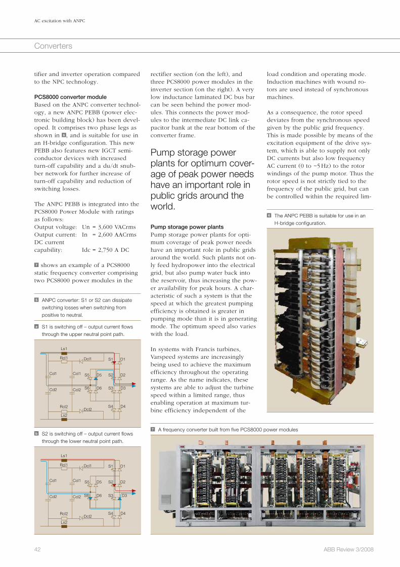
42 ABB Review 3/2008
AC excitation with ANPC
Converters
load condition and operating mode. Induction machines with wound ro-tors are used instead of synchronous machines.
As a consequence, the rotor speed deviates from the synchronous speed given by the public grid frequency. This is made possible by means of the excitation equipment of the drive sys-tem, which is able to supply not only DC currents but also low frequency AC current (0 to ~5 Hz) to the rotor windings of the pump motor. Thus the rotor speed is not strictly tied to the frequency of the public grid, but can be controlled within the required lim-
rectifier section (on the left), and three PCS8000 power modules in the inverter section (on the right). A very low inductance laminated DC bus bar can be seen behind the power mod-ules. This connects the power mod-ules to the intermediate DC link ca-pacitor bank at the rear bottom of the converter frame.
Pump storage power plants for optimum cover-age of peak power needs have an important role in public grids around the world.
Pump storage power plantsPump storage power plants for opti-mum coverage of peak power needs have an important role in public grids around the world. Such plants not on-ly feed hydropower into the electrical grid, but also pump water back into the reservoir, thus increasing the pow-er availability for peak hours. A char-acteristic of such a system is that the speed at which the greatest pumping efficiency is obtained is greater in pumping mode than it is in generating mode. The optimum speed also varies with the load.
In systems with Francis turbines, Varspeed systems are increasingly being used to achieve the maximum efficiency throughout the operating range. As the name indicates, these systems are able to adjust the turbine speed within a limited range, thus enabling operation at maximum tur-bine efficiency independent of the
tifier and inverter operation compared to the NPC technology.
PCS8000 converter moduleBased on the ANPC converter technol-ogy, a new ANPC PEBB (power elec-tronic building block) has been devel-oped. It comprises two phase legs as shown in 6 , and is suitable for use in an H-bridge configuration. This new PEBB also features new IGCT semi-conductor devices with increased turn-off capability and a du/dt snub-ber network for further increase of turn-off capability and reduction of switching losses.
The ANPC PEBB is integrated into the PCS8000 Power Module with ratings as follows:Output voltage: Un = 3,600 VACrmsOutput current: In = 2,600 AACrmsDC current capability: Idc = 2,750 A DC
7 shows an example of a PCS8000 static frequency converter comprising two PCS8000 power modules in the
5 ANPC converter: S1 or S2 can dissipate switching losses when switching from positive to neutral.
a S1 is switching off – output current flows through the upper neutral point path.
b S2 is switching off – output current flows through the lower neutral point path.
Cd1
Cd1
Ccl1
Ccl1
Ccl2
Ccl2
D6
D6
D5
D5
S5
S5
S6
S6
S2
S2
S1
S1
D2
D2
D1
D1
S3
S3
D3
D3
D4
D4
S4
S4
Ls1
Ls1
Rcl1
Rcl1
Rcl2
Rcl2
Ls2
Ls2
Dcl1
Dcl1
Dcl2
Dcl2
Cd2
Cd2
6 The ANPC PEBB is suitable for use in an H-bridge configuration.
7 A frequency converter built from five PCS8000 power modules
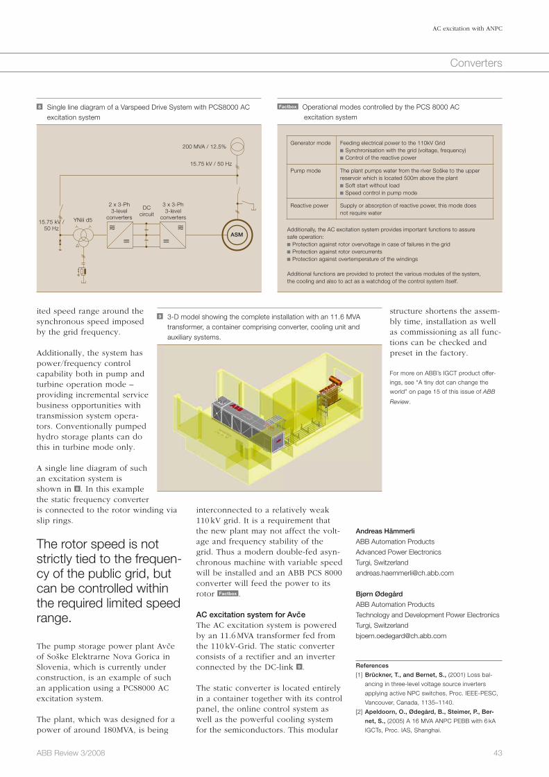
43ABB Review 3/2008
AC excitation with ANPC
Converters
structure shortens the assem-bly time, installation as well as commissioning as all func-tions can be checked and preset in the factory.
For more on ABB’s IGCT product offer-
ings, see “A tiny dot can change the
world” on page 15 of this issue of ABB
Review.
Andreas Hämmerli
ABB Automation Products
Advanced Power Electronics
Turgi, Switzerland
Bjørn Ødegård
ABB Automation Products
Technology and Development Power Electronics
Turgi, Switzerland
References
[1] Brückner, T., and Bernet, S., (2001) Loss bal-
ancing in three-level voltage source inverters
applying active NPC switches, Proc. IEEE-PESC,
Vancouver, Canada, 1135–1140.
[2] Apeldoorn, O., Ødegård, B., Steimer, P., Ber-
net, S., (2005) A 16 MVA ANPC PEBB with 6 kA
IGCTs, Proc. IAS, Shanghai.
inter connected to a relatively weak 110 kV grid. It is a requirement that the new plant may not affect the volt-age and frequency stability of the grid. Thus a modern double-fed asyn-chronous machine with variable speed will be installed and an ABB PCS 8000 converter will feed the power to its rotor Factbox . AC excitation system for AvceThe AC excitation system is powered by an 11.6 MVA transformer fed from the 110 kV-Grid. The static converter consists of a rectifier and an inverter connected by the DC-link 9 . The static converter is located entirely in a container together with its control panel, the online control system as well as the powerful cooling system for the semiconductors. This modular
ited speed range around the synchronous speed imposed by the grid frequency.
Additionally, the system has power/frequency control capability both in pump and turbine operation mode – providing incremental service business opportunities with transmission system opera-tors. Conventionally pumped hydro storage plants can do this in turbine mode only. A single line diagram of such an excitation system is shown in 8 . In this example the static frequency converter is connected to the rotor winding via slip rings.
The rotor speed is not strictly tied to the frequen-cy of the public grid, but can be controlled within the required limited speed range.
The pump storage power plant Avce of Soške Elektrarne Nova Gorica in Slovenia, which is currently under construction, is an example of such an application using a PCS8000 AC excitation system.
The plant, which was designed for a power of around 180MVA, is being
Factbox Operational modes controlled by the PCS 8000 AC excitation system
Generator mode
Feeding electrical power to the 110kV Grid Synchronisation with the grid (voltage, frequency) Control of the reactive power
Pump mode The plant pumps water from the river Soške to the upper reservoir which is located 500m above the plant Soft start without load Speed control in pump mode
Reactive power Supply or absorption of reactive power, this mode does not require water
Additionally, the AC excitation system provides important functions to assure safe operation: Protection against rotor overvoltage in case of failures in the grid Protection against rotor overcurrents Protection against overtemperature of the windings
Additional functions are provided to protect the various modules of the system, the cooling and also to act as a watchdog of the control system itself.
8 Single line diagram of a Varspeed Drive System with PCS8000 AC excitation system
2 x 3-Ph3-level
convertersYNiii d5
ASM
15.75 kV / 50 Hz
DC circuit
200 MVA / 12.5%
15.75 kV / 50 Hz
3 x 3-Ph3-level
converters
≈∼ ≈∼= =
9 3-D model showing the complete installation with an 11.6 MVA transformer, a container comprising converter, cooling unit and auxiliary systems.

44 ABB Review 3/2008
When electric transmission technology was developed more than one hundred years ago, local fossil-based energy sources in remote areas were replaced with renewable energy in the form of hydro power. At that time, transmission development was purely driven by the need to find new sources of energy rather than by environmental issues. Fast forward one hundred years and the situation looks quite different. Climate change combined with the need to reduce green house gas emissions, primarily CO2 levels, mean that environmental issues have now become the main driving force behind transmission technology development.
While electricity (and heating), with its present production and distribution methods, is the largest contributor to green house gases, it also represents the greatest potential in combat-ing climate change. Fossil fuels still produce much of the world’s electricity. However, the gen-eration of renewable energy from hydro, wind and solar power sources is steadily increasing. This, combined with transmission technology developments over the past 20 years, is key to finding a solution that not only significantly reduces CO2 levels, but in a cost effective way.
The solution is to connect renewable electric energy generated by hydro, wind, or solar power to the consumer using currently available ABB technologies.
Clean and invisibleNew transmission technologies are a valuable link to a clean and sustainable futureGunnar Asplund, Bo Normark
Converters
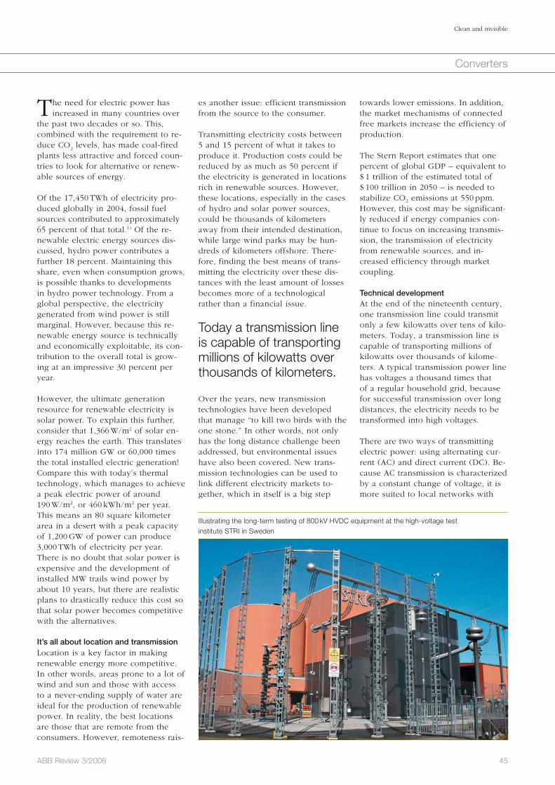
45ABB Review 3/2008
Clean and invisible
Converters
towards lower emissions. In addition, the market mechanisms of connected free markets increase the efficiency of production.
The Stern Report estimates that one percent of global GDP – equivalent to $ 1 trillion of the estimated total of $ 100 trillion in 2050 – is needed to stabilize CO2 emissions at 550 ppm. However, this cost may be significant-ly reduced if energy companies con-tinue to focus on increasing transmis-sion, the transmission of electricity from renewable sources, and in-creased efficiency through market coupling.
Technical developmentAt the end of the nineteenth century, one transmission line could transmit only a few kilowatts over tens of kilo-meters. Today, a transmission line is capable of transporting millions of kilowatts over thousands of kilome-ters. A typical transmission power line has voltages a thousand times that of a regular household grid, because for successful transmission over long distances, the electricity needs to be transformed into high voltages.
There are two ways of transmitting electric power: using alternating cur-rent (AC) and direct current (DC). Be-cause AC transmission is characterized by a constant change of voltage, it is more suited to local networks with
es another issue: efficient transmission from the source to the consumer.
Transmitting electricity costs between 5 and 15 percent of what it takes to produce it. Production costs could be reduced by as much as 50 percent if the electricity is generated in locations rich in renewable sources. However, these locations, especially in the cases of hydro and solar power sources, could be thousands of kilometers away from their intended destination, while large wind parks may be hun-dreds of kilometers offshore. There-fore, finding the best means of trans-mitting the electricity over these dis-tances with the least amount of losses becomes more of a technological rather than a financial issue.
Today a transmission line is capable of transporting millions of kilowatts over thousands of kilometers.
Over the years, new transmission technologies have been developed that manage “to kill two birds with the one stone.” In other words, not only has the long distance challenge been addressed, but environmental issues have also been covered. New trans-mission technologies can be used to link different electricity markets to-gether, which in itself is a big step
The need for electric power has increased in many countries over
the past two decades or so. This, combined with the requirement to re-duce CO
2 levels, has made coal-fired
plants less attractive and forced coun-tries to look for alternative or renew-able sources of energy.
Of the 17,450 TWh of electricity pro-duced globally in 2004, fossil fuel sources contributed to approximately 65 percent of that total.1) Of the re-newable electric energy sources dis-cussed, hydro power contributes a further 18 percent. Maintaining this share, even when consumption grows, is possible thanks to developments in hydro power technology. From a global perspective, the electricity generated from wind power is still marginal. However, because this re-newable energy source is technically and economically exploitable, its con-tribution to the overall total is grow-ing at an impressive 30 percent per year.
However, the ultimate generation resource for renewable electricity is solar power. To explain this further, consider that 1,366 W/m2 of solar en-ergy reaches the earth. This translates into 174 million GW or 60,000 times the total installed electric generation! Compare this with today’s thermal technology, which manages to achieve a peak electric power of around 190 W/m2, or 460 kWh/m2 per year. This means an 80 square kilometer area in a desert with a peak capacity of 1,200 GW of power can produce 3,000 TWh of electricity per year. There is no doubt that solar power is expensive and the development of installed MW trails wind power by about 10 years, but there are realistic plans to drastically reduce this cost so that solar power becomes competitive with the alternatives.
It’s all about location and transmissionLocation is a key factor in making renewable energy more competitive. In other words, areas prone to a lot of wind and sun and those with access to a never-ending supply of water are ideal for the production of renewable power. In reality, the best locations are those that are remote from the consumers. However, remoteness rais-
Illustrating the long-term testing of 800 kV HVDC equipment at the high-voltage test institute STRI in Sweden

46 ABB Review 3/2008
Clean and invisible
Converters
This challenge has already been ad-dressed by the development of an 800 kV ultra high-voltage direct cur-rent (UHVDC) transmission system.2) This transmission system is character-ized not only by its large power carry-ing capacity3), but when compared to traditional technologies, it occupies significantly less land and uses much less material 1 . In addition, it has an efficiency rating of over 94 percent!
ABB’s HVDC Light technology will connect a wind farm 128 km offshore with a substation 75 km inland.
The first 800 kV UHVDC systems are already under construction in China. The largest, built by the State Grid Corporation of China, will transmit 6,400 MW of power over a distance
head lines are either not permitted or where the time taken to obtain per-mission takes too long.
Connecting to remote hydro power Because of its ability to efficiently transmit power over long distances, HVDC transmission has been used primarily to connect mega cities, such as Boston, Montreal, Sao Paolo, Shanghai and Johannesburg to remote hydro power.
However, increasing demands and strict environmental regulations mean that more and more remote hydro power plants are being considered. While the evidence suggests that suffi-cient hydro power resources exist around the world to partly meet these demands, their availability heavily depends on an economic transmission technique. For example, an estimated 320 GW of renewable hydro power could be made available to consumers in Africa, Latin America and East Asia if investments in transmission were made. The addition of an extra 120 GW in Latin America is equivalent to 80 percent the total electricity pro-duced on the continent today. As well as hydro power, these areas would benefit enormously if solar power could be fully exploited. But the problem is these resources are located between 2,000 and 3,000 km from the load centers. New technology is required if these resources are to be successfully utilized.
many different access points rather than for the efficient transmission of power over distances greater than 500 km.
DC power transmission is better suited to transport power from remote power plants.
On the other hand, high-voltage direct current (HVDC) transmission can transmit more power per line, and is much more efficient and cost effective over large distances. In addition, the losses are quite low. Today’s HVDC transmission schemes can carry up to 3,000 MW of power over distances of between 1,000 and 1,500 km. A typical scheme consists of two stations that convert AC to DC and vice versa. It uses overhead lines or cables with only two conductors – one carrying + 500 kV and the other carrying – 500 kV, giving a total of one million volts.
A new transmission technology known as HVDC Light® has been de-veloped in the last few years. It utiliz-es transistors instead of thyristors for the conversion process, and rather than overhead lines, HVDC Light uses underground cables between stations. Currently, HVDC Light is used to transfer power from offshore wind parks, for example, and to strengthen the electrical grid in areas where over-
1 The 800 kV UHVDC transmission system has an efficiency rating of 94 percent and uses significantly less land than traditional
technologies.
Transmission 6.400 MW / 2000 km
800 kV AC Efficiency
88%
94%
800 kV UHV DC
Footnotes1) It takes nature a year to recreate the fossil fuels that
are consumed in only 10 seconds.2) The voltage between the conductors is 1.6 million
volts. 3) A UHVDC transmission system requires an extremely
reliable control system with built-in redundancy.
For this purpose, ABB has further enhanced its
well-known MACH 2™ system to create the
DCC 800 control system.

47ABB Review 3/2008
Clean and invisible
Converters
HVDC Light currently supports a power level of 1,100 MW with a cable voltage of ± 300 kV. Additionally, be-cause a cable has a controlled envi-ronment compared to an overhead line, the risk of flashover4) is signifi-cantly reduced.
Developments in renew-able generation and trans-mission technologies make it possible to have a totally renewable electrical system in Europe.
Connecting remote solar powerIs it possible to have a totally renew-able electrical system in Europe? The answer, in a nutshell, is yes. There is an almost unlimited source of solar power. If it could be harnessed prop-
The German energy company, E.ON, is currently constructing the first major transmission system of this type in the North Sea. With a carrying capacity of 400 MW, it will connect a wind farm 128 km off the coast with a substation located 75 km inland 2 . The entire transmission system is invisible and there are no electro-magnetic field (EMF) emissions, making it a very at-tractive solution. In total, four clusters are planned in the area, each with a capacity to generate at least 1,500 MW of wind power.
As more wind power installations are developed, there is an increasing need to balance power when winds are low. The HVDC Light system solves this problem by interconnecting off-shore wind power plants with differ-ent countries and markets. Several such schemes are planned in Northern Europe.
of 2,071 km (1,286 miles) from the Xiangjiaba hydro power plant in the southwest of China to Shanghai.
Connecting to offshore wind powerWind power is rapidly becoming a mainstream production resource for electricity. In 2007, wind power ac-counted for 40 percent of all new in-stalled generated power. But if it is to be further developed, especially in Europe, an increasing share of new wind power plants will have to be built offshore. In fact it is foreseen that up to 40 percent of all new instal-lations in the next few decades will be offshore primarily for environmen-tal reasons. The higher cost of build-ing offshore plants can be partly off-set by higher production. But yet again, connecting to the grid becomes a major challenge. Traditional AC transmission is only suitable for installations within 50 km of the shoreline.
In larger offshore installations, “clus-tering” many wind farms and building fewer but larger transmission systems has proven to be very beneficial. The use of HVDC Light technology is ideal for these installations because the converters are relatively compact, making them easier to install on off-shore platforms. The converters can also provide the necessary electrical functionality to give the desired per-formance as well as voltage and fre-quency stability during fault condi-tions.
A computer-generated illustration of an 800 kV converter station
2 E.ON is currently constructing a HVDC Light transmission system in the North Sea, which will have a carrying capacity of 400 MW.
Power 400 MW
400 MW offshore converter
400 MW land converter
Offshore Windpark-ClusterBorkum 2
largest offshore wind park in the world
largest distance from mainland
first grid connection with direct current in Germany
Sylt DENMARK
128 km sea cable
BorkumNorden
Emden
Substation Diele
Bremer-haven
CuxhavenScharhörn
Helgoland
Wilhelms-haven
75 kmland cable
NETHERLANDS
Tailwind for grid reliability
3 A totally renewable electrical system is possible if solar power could be harnessed properly and combined with hydro, wind and pump storage.
Hydro power
Solar power
Wind power
DC transmission

48 ABB Review 3/2008
Clean and invisible
Converters
ty are technically at hand and economically within reach. Several new technologies for generating and storing elec-tricity, as well as using elec-tricity for cleaner transporta-tion and industrial processes, are evolving. More sophisti-cated market mechanisms foster efficiency and change. The key to all these positive developments is transmission – the need to “cleanly” trans-port electricity from where it is generated to where it is consumed.
Gunnar Asplund
Bo Normark
ABB Power Systems
Västerås, Sweden
Footnotes4) A flashover is an unintended high-voltage electric
discharge over or around an insulator, or arcing or
sparking between two or more adjacent conduc-
tors. Source: http://en.wikipedia.org/wiki/Flashover,
(May 2008).5) The cost of overhead lines varies from country to
country.6) This should be possible without having to increase
the insulation thickness.
erly and combined with hydro, wind and pump stor-age, then the dream of many could be turned into reality 3 . In fact, building the re-quired grid is technically and economically feasible. So what would it therefore cost to build the required trans-mission system and what effi-ciency would it have?
Using the current conditions in China and India as a refer-ence5), an HVDC transmission system transmitting 6,400 MW of power over a distance of 3,000 km would cost less than $ 2.8 billion 4 . This figure includes the cost of the line losses, which would be rated at just over five per-cent.
Extending current limitsSome years ago, the idea of a renewable energy system was technically out of reach and economically unthinkable. Since then, dramatic develop-ments in renewable genera-tion and transmission tech-nologies is turning the “un-thinkable” in to the “very likely.” Today, it is possible to transmit at least 6,000 MW of power per line from the Sahara dessert to central and northern Europe. To transmit 700 TWh, a transmission capacity of around 150 GW, requiring around 25 lines, would be needed at a total cost (using current European conditions) of approximately 100 billion euros, or roughly 1 euro cents/KWh 5 .
With accelerated research and development, cable developments can significantly reduce this figure. If, as expected, the power and voltage rating of HVDC Light cables6) increase significantly within the next few de-cades, then it will be possible to cost-effectively transmit several gigawatts of power completely underground 6 . However, the DC voltage needs to be raised to 1,200 kV to achieve the same power transfer capability as overhead lines. If current cables impregnated
4 The estimated cost of a system (lines, stations and losses) that would transmit 6,400 MW a distance of 3,000 km
Percent line losses
1 2 3 4 5 6 7 8 9 10
5,000
4,500
4,000
3,500
3,000
2,500
2,000
1,500
1,000
Mill
ion
$
5 To transmit 700 TWh, a transmission capacity of around 150 GW would be needed at a total cost of approximately 100 billion euros,or roughly 1 euro cents/KWh.
300 400 500 600 700 800 900 1,000 1,100 1,200
1.2
1.0
0.8
0.6
0.4
0.2
0.0
Cos
t in
A c
ent/
kWh
Cable voltage in kV
Cables and converter stations 800 kV OH lines and converter stations
6 Research and development will enable a significant increase in the power that can be transmitted in a pair of HVDC Light® cables.
300 450 600 750 900 1,050 1,200
6,000
5,000
4,000
3,000
2,000
1,000
0
Pow
er in
MW
Direct voltage in kV
with oil can withstand 500 kV, is it realistic to expect this level to rise by almost a factor of three? In theory, yes, because when compared with cables, capacitors have an insulation system that can withstand much high-er voltage stresses. If the same stress-es could be applied to cables, they would withstand up to 4,000 kV.
In any case, the prospects of radically reducing CO2 emissions from electrici-

49ABB Review 3/2008
Converters
Electric railways have a huge demand for power. In fact many operate their own high-voltage power grids and some even own their own generating plants. Few railways, however, are totally autonomous: Power must be exchanged with the national grids. This is not as simple as it may at first seem. For historical reasons, many railway systems are electrified at frequencies other than those of the domestic grids, and furthermore, they are not always synchronized.
The railway connectionFrequency converters for railway power supplyGerhard Linhofer, Philippe Maibach, Niklaus Umbricht
Historically, rotating machines were used to transform electricity from one frequency to another, with auxiliary equipment being added where need-ed to compensate for the frequency slip – within certain limits. The state-of-the-art solution is a different one however: New installations use large frequency converters based entirely on power electronics. These offer numerous advantages including faster response times and the ability to pro-vide improved reactive power control.
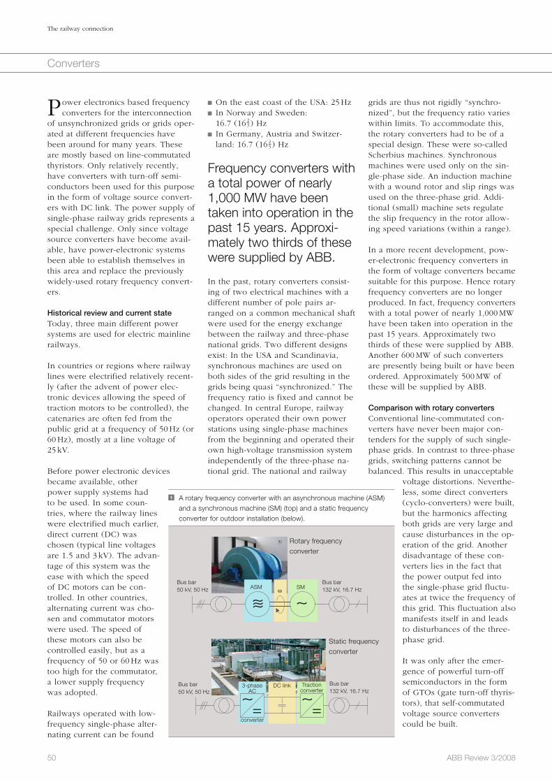
grids are thus not rigidly “synchro-nized”, but the frequency ratio varies within limits. To accommodate this, the rotary converters had to be of a special design. These were so-called Scherbius machines. Synchronous machines were used only on the sin-gle-phase side. An induction machine with a wound rotor and slip rings was used on the three-phase grid. Addi-tional (small) machine sets regulate the slip frequency in the rotor allow-ing speed variations (within a range).
In a more recent development, pow-er-electronic frequency converters in the form of voltage converters became suitable for this purpose. Hence rotary frequency converters are no longer produced. In fact, frequency converters with a total power of nearly 1,000 MW have been taken into operation in the past 15 years. Approximately two thirds of these were supplied by ABB. Another 600 MW of such converters are presently being built or have been ordered. Approximately 500 MW of these will be supplied by ABB.
Comparison with rotary convertersConventional line-commutated con-verters have never been major con-tenders for the supply of such single-phase grids. In contrast to three-phase grids, switching patterns cannot be balanced. This results in unacceptable
voltage distortions. Neverthe-less, some direct converters (cyclo-converters) were built, but the harmonics affecting both grids are very large and cause disturbances in the op-eration of the grid. Another disadvantage of these con-verters lies in the fact that the power output fed into the single-phase grid fluctu-ates at twice the frequency of this grid. This fluctuation also manifests itself in and leads to disturbances of the three-phase grid.
It was only after the emer-gence of powerful turn-off semiconductors in the form of GTOs (gate turn-off thyris-tors), that self-commutated voltage source converters could be built.
On the east coast of the USA: 25 Hz In Norway and Sweden: 16.7 (16 ) Hz
In Germany, Austria and Switzer-land: 16.7 (16 ) Hz
Frequency converters with a total power of nearly 1,000 MW have been taken into operation in the past 15 years. Approxi-mately two thirds of these were supplied by ABB.
In the past, rotary converters consist-ing of two electrical machines with a different number of pole pairs ar-ranged on a common mechanical shaft were used for the energy exchange between the railway and three-phase national grids. Two different designs exist: In the USA and Scandinavia, synchronous machines are used on both sides of the grid resulting in the grids being quasi “synchronized.” The frequency ratio is fixed and cannot be changed. In central Europe, railway operators operated their own power stations using single-phase machines from the beginning and operated their own high-voltage transmission system independently of the three-phase na-tional grid. The national and railway
Power electronics based frequency converters for the interconnection
of unsynchronized grids or grids oper-ated at different frequencies have been around for many years. These are mostly based on line-commutated thyristors. Only relatively recently, have converters with turn-off semi-conductors been used for this purpose in the form of voltage source convert-ers with DC link. The power supply of single-phase railway grids represents a special challenge. Only since voltage source converters have become avail-able, have power-electronic systems been able to establish themselves in this area and replace the previously widely-used rotary frequency convert-ers.
Historical review and current stateToday, three main different power systems are used for electric mainline railways.
In countries or regions where railway lines were electrified relatively recent-ly (after the advent of power elec-tronic devices allowing the speed of traction motors to be controlled), the catenaries are often fed from the public grid at a frequency of 50 Hz (or 60 Hz), mostly at a line voltage of 25 kV.
Before power electronic devices became available, other power supply systems had to be used. In some coun-tries, where the railway lines were electrified much earlier, direct current (DC) was chosen (typical line voltages are 1.5 and 3 kV). The advan-tage of this system was the ease with which the speed of DC motors can be con-trolled. In other countries, alternating current was cho-sen and commutator motors were used. The speed of these motors can also be controlled easily, but as a frequency of 50 or 60 Hz was too high for the commutator, a lower supply frequency was adopted.
Railways operated with low-frequency single-phase alter-nating current can be found
50 ABB Review 3/2008
The railway connection
Converters
3-phase AC
converter
DC link Traction converter
1 A rotary frequency converter with an asynchronous machine (ASM) and a synchronous machine (SM) (top) and a static frequency converter for outdoor installation (below).
Rotary frequency converter
Static frequency converter
Bus bar50 kV, 50 Hz
Bus bar50 kV, 50 Hz
Bus bar132 kV, 16.7 Hz
Bus bar132 kV, 16.7 Hz
ASM SMω
∼≈ ∼
∼ ∼= =
23
23
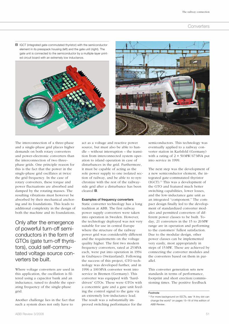
51ABB Review 3/2008
The railway connection
Converters
semiconductors. This technology was eventually applied to a railway con-verter station in Karlsfeld (Germany) with a rating of 2 × 50 MW/67 MVA put into service in 1999.
The next step was the development of a new semiconductor element, the in-tegrated gate-commutated thyristor (IGCT).1) This was a development of the GTO and featured much better switching capabilities, lower losses, and the low-inductance gate unit as an integrated “component.” The com-pact design finally led to the develop-ment of standardized converter mod-ules and permitted converters of dif-ferent power classes to be built. To-day, 21 converters in the 15 to 20 MW range are in operation and performing to the customers’ fullest satisfaction. Due to the modular design, other power classes can be implemented very easily, most appropriately in steps of 15 MW. These are achieved by connecting the converter modules and the converters based on them in par-allel.
This converter generation sets new standards in terms of performance, footprint and short erection/commis-sioning times. The positive feedback
act as a voltage and reactive power source, but must also be able to han-dle – without interruption – the transi-tion from interconnected system oper-ation to island operation in case of disturbances in the grid. Furthermore, it must be capable of acting as the sole power supply to one isolated sec-tion of railway, and be able to re-syn-chronize with the rest of the railway-side grid after a disturbance has been cleared 1 .
Examples of frequency convertersStatic converter technology has a long tradition at ABB. The first railway power supply converters were taken into operation in Sweden. However, the technology deployed was not very suitable for use in central Europe where the structure of the railway power grid was considerably different and the requirements on the voltage quality higher. The first two modern frequency converters, rated at 25 MVA each, were put into operation in 1994 in Giubiasco (Switzerland). Following the success of this project, GTO tech-nology was developed further, and in 1996 a 100 MVA converter went into service in Bremen (Germany). This converter was equipped with “hard-driven” GTOs. These were GTOs with a concentric gate and a gate unit feed-ing the control signal to the gate via an extremely low-inductance lead. The result was a substantially im-proved switching performance for the
The interconnection of a three-phase and a single-phase grid places higher demands on both rotary converters and power-electronic converters than the interconnection of two three-phase grids. One principle reason for this is the fact that the power in the single-phase grid oscillates at twice the grid frequency. In the case of rotary converters, these torque and power fluctuations are absorbed and damped by the rotating masses. The resulting vibrations must however be absorbed by their mechanical anchor-ing and its foundations. This leads to additional complexity in the design of both the machine and its foundations.
Only after the emergence of powerful turn-off semi-conductors in the form of GTOs (gate turn-off thyris-tors), could self-commu-tated voltage source con-verters be built.
Where voltage converters are used in this application, the oscillation is fil-tered using a capacitor bank and an inductance, tuned to double the oper-ating frequency of the single-phase grid.
Another challenge lies in the fact that such a system does not only have to
2 IGCT (integrated gate-commutated thyristor) with the semiconductor element in its presspack housing (left) and the gate unit (right). The gate unit is connected to the semiconductor by a multiple-layer print-ed circuit board with an extremely low inductance.
Footnote1) For more background on IGCTs, see “A tiny dot can
change the world” on pages 15–18 of this edition of
ABB Review.

52 ABB Review 3/2008
The railway connection
Converters
(a water-glycol mixture) is fed via hose connections to the heat sinks. The mechanical structure of the dou-ble stack allows a very compact de-sign. This helps achieve the required low stray inductance values within the stack allowing the semiconductors to be utilized to the optimum. Neverthe-less, access to all semiconductors in the stack is still possible permitting easy replacement. Each semiconductor can be replaced with the help of a simple tool without interrupting the cooling circuit. 4 shows an example of such a double stack.
Example: 15–20 MW class converter5 shows the schematic of a complete converter station.
50 Hz converter (SR50)The 50 Hz converter 5a has the follow-ing attributes: Design: The 50 Hz converter con-sists of two standard three-phase, three-level units. Two phases are combined in one stack to form a double-phase module. A double-phase module of a three-level unit consists of eight IGCTs combined with eight freewheeling diodes, and four freewheeling diodes on the neutral conductor. The gate unit and the GCT form an integrated unit, the IGCT. The clamping circuit serves as a di/dt limiter and voltage limiter. It consists of current-limiting reactors, capacitors and clamp diodes with resistors.
Circuitry and control method: The 50 Hz converter is built in real 12-pulse configuration. Hence, only 12-pulse characteristic harmonics (n = 12 k ± 1; k = 1, 2, 3, 4 . . . ) are generated. Depending on the cho-sen semiconductor switching fre-quency and the modulation strategy, some of the remaining harmonics can be cancelled. If needed, the harmonics can be damped to even lower values by applying a line filter.
16.7 Hz converterThe 16.7 Hz converter 5b has the following attributes: Design: The 16.7 Hz converter con-sists of four standard two-phase, three-level units. Two phases are combined in one stack assembly to form a double-phase module, which
should not be too low because of the harmonics generated. Hence, there is an optimization potential between losses and harmonics. An elegant way to partially overcome this dilemma is to choose a multi-level topology. This allows the converter to be operated with a relatively low switching fre-quency and at the same time achieve good harmonic performance.
The IGCT combines the advantages of the GTO and the IGBT, ie, robust-ness, low switching and conduction losses as well as a fast switching capability.
Three-level phase modules are used to generate an AC voltage from a DC volt-age. Such modules can be considered as changeover switches with three positions: The output can be switched to the positive (+), neutral (0) or nega-tive potential (-) of the DC link 3 .
Two-phase modules of this type are combined to a three-level double-phase module. All IGCTs are cooled on both sides. The cooling medium
from customers shows that the stan-dardized railway converter from ABB is well suited to cover their needs.
The base moduleThe “heart” of the converter module, the IGCT, is shown in 2 . The IGCT combines the advantages of the GTO and the IGBT (insulated-gate bipolar transistor), ie, robustness, low switch-ing and conduction losses as well as a fast switching capability. The proper-ties of this semiconductor element re-main unsurpassed for the application discussed here (high power, medium voltage). An IGBT for the same appli-cation (high-voltage IGBT, IEGT), for example, exhibits comparable switch-ing losses in relation to the same sili-con surface, but considerably higher conduction losses. Furthermore, the IGCT allows a converter design with minimal additional circuitry. For ex-ample, a phase module only requires a simple snubber circuit whereas each GTO requires extensive circuitry. This results in advantages in terms of costs, compactness and losses.
Losses occur whenever a semiconduc-tor conducts current or is switched. Such losses can be minimized by low-ering the switching frequency. On the other hand, the switching frequency
+
U =
0
-
3 Operating principle of the three-level converter module and its implementation with semiconductor devices
+
0
-
U =
AC
S1
S2
S3
S4
a b
4 Mechanical structure of a double stack and the corresponding circuit diagram
+
+
0
0 AC 1
AC 1-
-
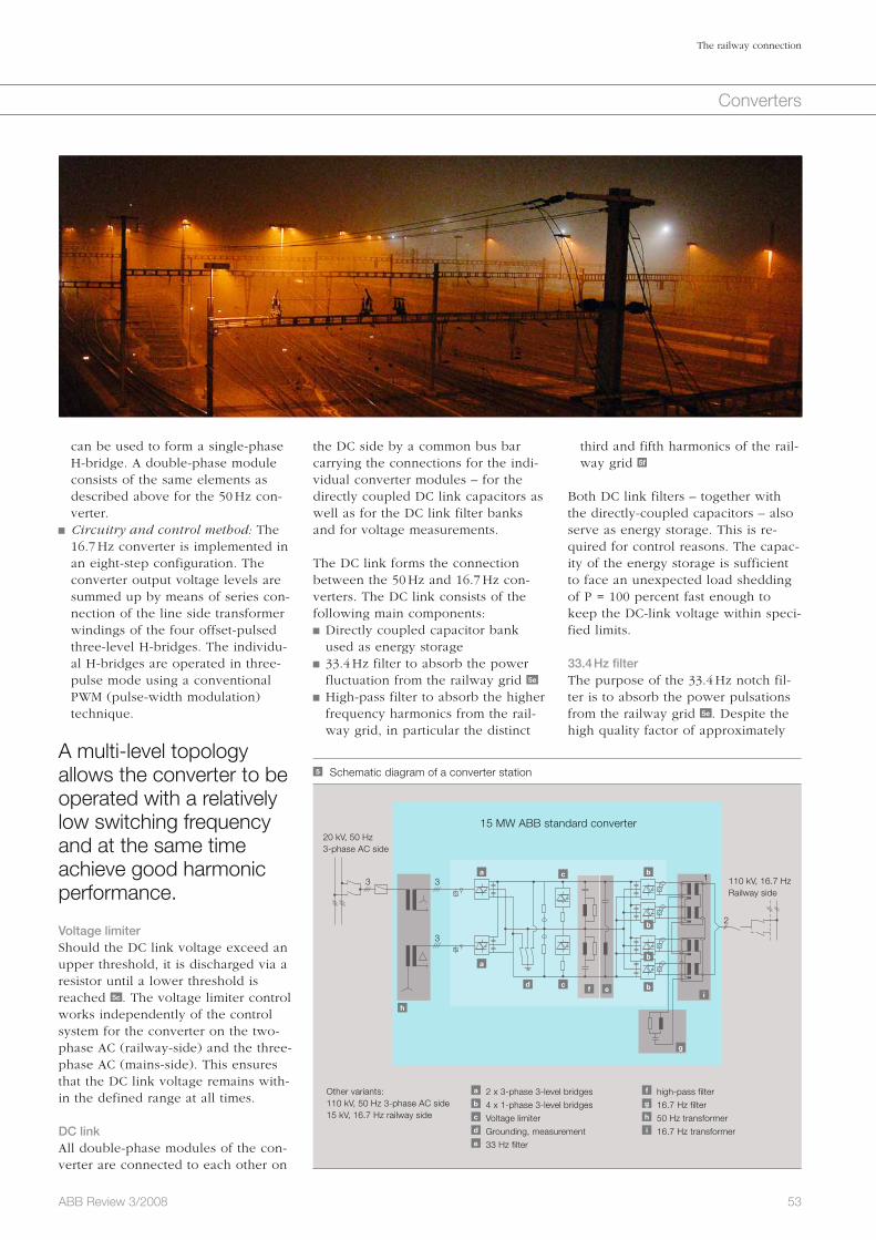
53ABB Review 3/2008
The railway connection
Converters
can be used to form a single-phase H-bridge. A double-phase module consists of the same elements as described above for the 50 Hz con-verter.
Circuitry and control method: The 16.7 Hz converter is implemented in an eight-step configuration. The converter output voltage levels are summed up by means of series con-nection of the line side transformer windings of the four offset-pulsed three-level H-bridges. The individu-al H-bridges are operated in three-pulse mode using a conventional PWM (pulse-width modulation) technique.
A multi-level topology allows the converter to be operated with a relatively low switching frequency and at the same time achieve good harmonic performance.
Voltage limiterShould the DC link voltage exceed an upper threshold, it is discharged via a resistor until a lower threshold is reached 5c . The voltage limiter control works independently of the control system for the converter on the two-phase AC (railway-side) and the three-phase AC (mains-side). This ensures that the DC link voltage remains with-in the defined range at all times.
DC linkAll double-phase modules of the con-verter are connected to each other on
the DC side by a common bus bar carrying the connections for the indi-vidual converter modules – for the directly coupled DC link capacitors as well as for the DC link filter banks and for voltage measurements.
The DC link forms the connection between the 50 Hz and 16.7 Hz con-verters. The DC link consists of the following main components: Directly coupled capacitor bank used as energy storage
33.4 Hz filter to absorb the power fluctuation from the railway grid 5e
High-pass filter to absorb the higher frequency harmonics from the rail-way grid, in particular the distinct
third and fifth harmonics of the rail-way grid 5f
Both DC link filters – together with the directly-coupled capacitors – also serve as energy storage. This is re-quired for control reasons. The capac-ity of the energy storage is sufficient to face an unexpected load shedding of P = 100 percent fast enough to keep the DC-link voltage within speci-fied limits.
33.4 Hz filterThe purpose of the 33.4 Hz notch fil-ter is to absorb the power pulsations from the railway grid 5e . Despite the high quality factor of approximately
5 Schematic diagram of a converter station
20 kV, 50 Hz3-phase AC side
110 kV, 16.7 HzRailway side
Other variants:110 kV, 50 Hz 3-phase AC side15 kV, 16.7 Hz railway side
a 2 x 3-phase 3-level bridgesb 4 x 1-phase 3-level bridgesc Voltage limiterd Grounding, measuremente 33 Hz filter
f high-pass filterg 16.7 Hz filterh 50 Hz transformeri 16.7 Hz transformer
3 3
3
2
1
15 MW ABB standard converter
d
c
c
a
h
a
f e
b
b
b
b
g
i
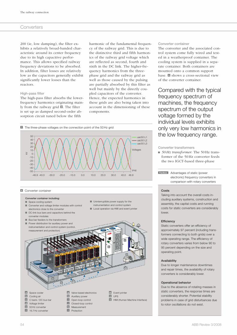
54 ABB Review 3/2008
The railway connection
Converters
Converter containerThe converter and the associated con-trol system come fully wired and test-ed in a weatherproof container. The cooling system is supplied in a sepa-rate container. Both containers are mounted onto a common support base. 6 shows a cross-sectional view of the converter container.
Compared with the typical frequency spectrum of machines, the frequency spectrum of the output voltage formed by the individual levels exhibits only very low harmonics in the low frequency range.
Converter transformers 50 Hz transformer: The 50 Hz trans-former of the 50 Hz converter feeds the two IGCT-based three-phase
harmonic of the fundamental frequen-cy of the railway grid. This is due to the distinctive third and fifth harmon-ics of the railway grid voltage which are reflected as second, fourth and sixth in the DC link. The higher-fre-quency harmonics from the three-phase grid and the railway grid as well as those caused by the pulsing are partially absorbed by this filter as well but mainly by the directly cou-pled capacitors of the converter. Hence, the expected harmonics in these grids are also being taken into account in the dimensioning of these components.
200 (ie, low damping), the filter ex-hibits a relatively broad-banded char-acteristic around its center frequency due to its high capacitive perfor-mance. This allows specified railway frequency deviations to be absorbed. In addition, filter losses are relatively low as the capacitors generally exhibit significantly lower losses than the reactors.
High-pass filterThe high-pass filter absorbs the lower-frequency harmonics originating main-ly from the railway grid 5f . The filter is set up as damped second-order ab-sorption circuit tuned below the fifth
Factbox Advantages of static (power electronic) frequency converters in
comparison with rotary converters
Costs
Taking into account the overall costs in-cluding auxiliary systems, construction and assembly, the capital costs and running costs for static converters are considerably lower.
Efficiency
Static converters offer an efficiency of approximately 97 percent (including trans-formers connecting to both grids) over a wide operating range. The efficiency of rotary converters varies from below 90 to 95 percent depending on the size and operating point.
Availability
Due to longer maintenance downtimes and repair times, the availability of rotary converters is considerably lower.
Operational behavior
Due to the absence of rotating masses in static converters, the response times are considerably shorter. Potential stability problems in case of grid disturbances due to rotor oscillations do not exist.
6 Converter container
a Space coolerb Cooling airc C bank / DC bus bard Voltage limitere 50 Hz converterf 16.7 Hz converter
g Valve-based electronicsh Auxiliary poweri Open-loop controlj Closed-loop controlk Measurementl Protection
m Event printern UPSo HMI (Human Machine Interface)
Converter container including:
Space cooling system
Converter and voltage limiter modules with control
electronics close to the converter
DC-link bus bars and capacitors behind the
converter modules
Bus bar feeders to the transformers
Power distribution for auxiliary power and
instrumentation and control system (control,
measurement and protection)
Uninterruptible power supply for the
instrumentation and control system
Local operation via HMI and event printer
a
b
c
de e
ef
ff
f
gg
gg
gg
g
h
i
j
k
l
n
o
m
7 The three-phase voltages on the connection point of the 50 Hz grid
(ms)
Voltages
uac50 L1 uac50 L2 uac50 L3
-46.9 -40.0 -30.0 -20.0 -10.0 0.0 10.0 20.0 30.0 40.0 46.9
kV
5040302010
0-10-20-30-40-50
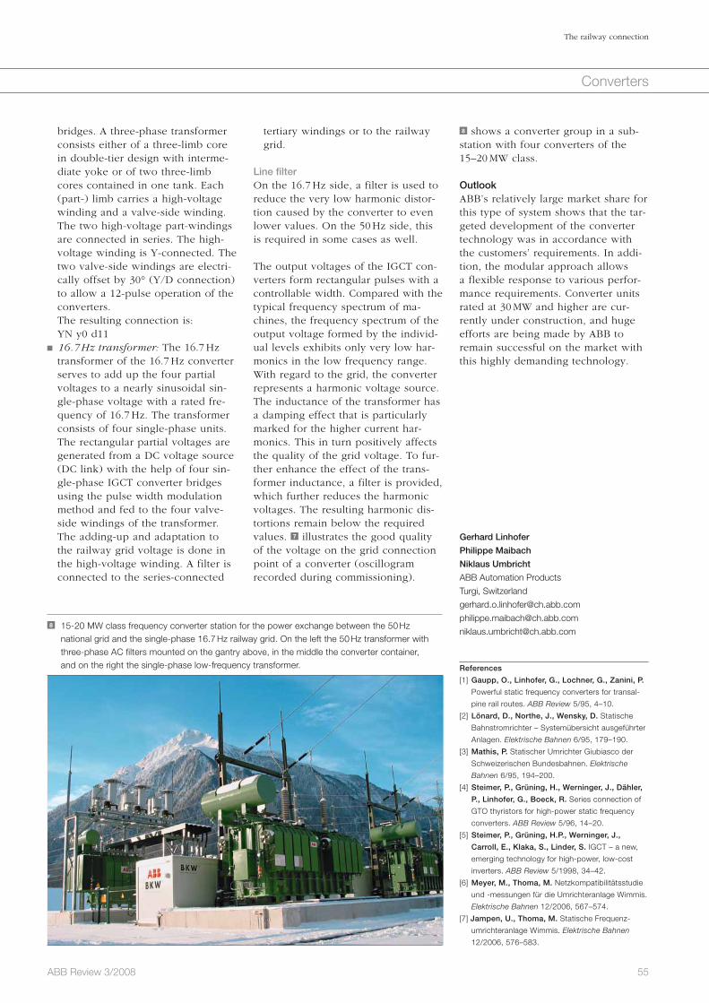
55ABB Review 3/2008
The railway connection
Converters
bridges. A three-phase transformer consists either of a three-limb core in double-tier design with interme-diate yoke or of two three-limb cores contained in one tank. Each (part-) limb carries a high-voltage winding and a valve-side winding. The two high-voltage part-windings are connected in series. The high-voltage winding is Y-connected. The two valve-side windings are electri-cally offset by 30° (Y/D connection) to allow a 12-pulse operation of the converters.
The resulting connection is: YN y0 d11
16.7 Hz transformer: The 16.7 Hz transformer of the 16.7 Hz converter serves to add up the four partial voltages to a nearly sinusoidal sin-gle-phase voltage with a rated fre-quency of 16.7 Hz. The transformer consists of four single-phase units. The rectangular partial voltages are generated from a DC voltage source (DC link) with the help of four sin-gle-phase IGCT converter bridges using the pulse width modulation method and fed to the four valve-side windings of the transformer. The adding-up and adaptation to the railway grid voltage is done in the high-voltage winding. A filter is connected to the series-connected
tertiary windings or to the railway grid.
Line filterOn the 16.7 Hz side, a filter is used to reduce the very low harmonic distor-tion caused by the converter to even lower values. On the 50 Hz side, this is required in some cases as well.
The output voltages of the IGCT con-verters form rectangular pulses with a controllable width. Compared with the typical frequency spectrum of ma-chines, the frequency spectrum of the output voltage formed by the individ-ual levels exhibits only very low har-monics in the low frequency range. With regard to the grid, the converter represents a harmonic voltage source. The inductance of the transformer has a damping effect that is particularly marked for the higher current har-monics. This in turn positively affects the quality of the grid voltage. To fur-ther enhance the effect of the trans-former inductance, a filter is provided, which further reduces the harmonic voltages. The resulting harmonic dis-tortions remain below the required values. 7 illustrates the good quality of the voltage on the grid connection point of a converter (oscillogram recorded during commissioning).
8 shows a converter group in a sub-station with four converters of the 15–20 MW class.
OutlookABB’s relatively large market share for this type of system shows that the tar-geted development of the converter technology was in accordance with the customers’ requirements. In addi-tion, the modular approach allows a flexible response to various perfor-mance requirements. Converter units rated at 30 MW and higher are cur-rently under construction, and huge efforts are being made by ABB to remain successful on the market with this highly demanding technology.
Gerhard Linhofer
Philippe Maibach
Niklaus Umbricht
ABB Automation Products
Turgi, Switzerland
References
[1] Gaupp, O., Linhofer, G., Lochner, G., Zanini, P.
Powerful static frequency converters for transal-
pine rail routes. ABB Review 5/95, 4–10.
[2] Lönard, D., Northe, J., Wensky, D. Statische
Bahnstromrichter – Systemübersicht ausgeführter
Anlagen. Elektrische Bahnen 6/95, 179–190.
[3] Mathis, P. Statischer Umrichter Giubiasco der
Schweizerischen Bundesbahnen. Elektrische
Bahnen 6/95, 194–200.
[4] Steimer, P., Grüning, H., Werninger, J., Dähler,
P., Linhofer, G., Boeck, R. Series connection of
GTO thyristors for high-power static frequency
converters. ABB Review 5/96, 14–20.
[5] Steimer, P., Grüning, H.P., Werninger, J.,
Carroll, E., Klaka, S., Linder, S. IGCT – a new,
emerging technology for high-power, low-cost
inverters. ABB Review 5/1998, 34–42.
[6] Meyer, M., Thoma, M. Netzkompatibilitätsstudie
und -messungen für die Umrichteranlage Wimmis.
Elektrische Bahnen 12/2006, 567–574.
[7] Jampen, U., Thoma, M. Statische Frequenz-
umrichteranlage Wimmis. Elektrische Bahnen
12/2006, 576–583.
8 15-20 MW class frequency converter station for the power exchange between the 50 Hz national grid and the single-phase 16.7 Hz railway grid. On the left the 50 Hz transformer with three-phase AC filters mounted on the gantry above, in the middle the converter container, and on the right the single-phase low-frequency transformer.
56 ABB Review 3/2008
Converters
Offshore but onlinePCS6000 wind converter for 5 MW offshore wind turbinesMarkus Eichler
Wind power has experienced stupen-dous growth levels over recent years. Not only are countless new installa-tions going online, but the turbines are growing larger and more powerful. The largest turbines now generate 5MW of power and stand almost as high as the spires of Cologne’s world-famous cathedral.
Wind farms are increasingly being built offshore or in sparsely inhabited regions, making not only their con-struction more and more challenging, but also their connection to the grid. ABB’s PCS 6000 converter addresses the latter issues. The converter fits neatly inside the mast of the turbine. Besides converting the generated power to the desired frequency and voltage, it helps support weak grids by supplying or absorbing reactive power.
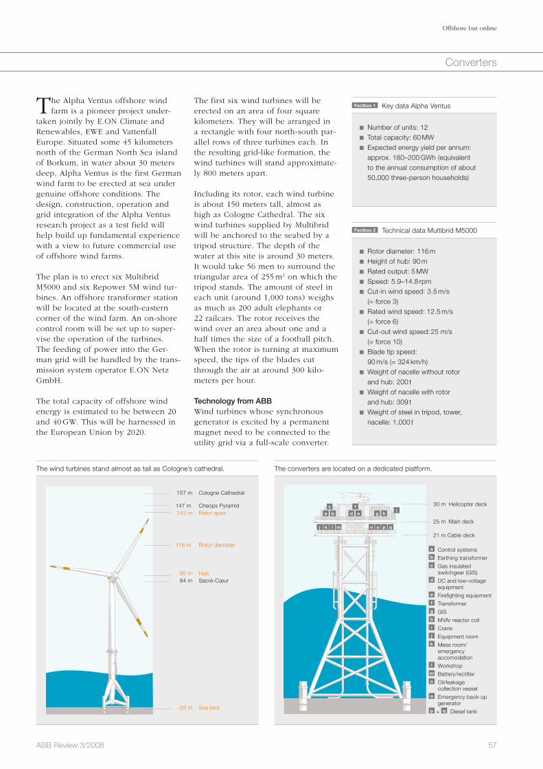
57ABB Review 3/2008
Offshore but online
Converters
The first six wind turbines will be erected on an area of four square kilo meters. They will be arranged in a rectangle with four north-south par-allel rows of three turbines each. In the resulting grid-like formation, the wind turbines will stand approximate-ly 800 meters apart.
Including its rotor, each wind turbine is about 150 meters tall, almost as high as Cologne Cathedral. The six wind turbines supplied by Multibrid will be anchored to the seabed by a tripod structure. The depth of the water at this site is around 30 meters. It would take 56 men to surround the triangular area of 255 m2 on which the tripod stands. The amount of steel in each unit (around 1,000 tons) weighs as much as 200 adult elephants or 22 railcars. The rotor receives the wind over an area about one and a half times the size of a football pitch. When the rotor is turning at maximum speed, the tips of the blades cut through the air at around 300 kilo-meters per hour.
Technology from ABBWind turbines whose synchronous generator is excited by a permanent magnet need to be connected to the utility grid via a full-scale converter.
The Alpha Ventus offshore wind farm is a pioneer project under-
taken jointly by E.ON Climate and Renewables, EWE and Vattenfall Europe. Situated some 45 kilometers north of the German North Sea island of Borkum, in water about 30 meters deep, Alpha Ventus is the first German wind farm to be erected at sea under genuine offshore conditions. The design, construction, operation and grid integration of the Alpha Ventus research project as a test field will help build up fundamental experience with a view to future commercial use of offshore wind farms.
The plan is to erect six Multibrid M5000 and six Repower 5M wind tur-bines. An offshore transformer station will be located at the south-eastern corner of the wind farm. An on-shore control room will be set up to super-vise the operation of the turbines. The feeding of power into the Ger-man grid will be handled by the trans-mission system operator E.ON Netz GmbH.
The total capacity of offshore wind energy is estimated to be between 20 and 40 GW. This will be harnessed in the European Union by 2020.
The wind turbines stand almost as tall as Cologne’s cathedral.
157 m Cologne Cathedral 147 m Cheops Pyramid 143 m Rotor apex
116 m Rotor diameter
85 m Hub 84 m Sacré-Cœur
-28 m Sea bed
Factbox 1 Key data Alpha Ventus
Number of units: 12 Total capacity: 60 MW Expected energy yield per annum: approx. 180–200 GWh (equivalent to the annual consumption of about 50,000 three-person households)
Factbox 2 Technical data Multibrid M5000
Rotor diameter: 116 m Height of hub: 90 m Rated output: 5 MW Speed: 5.9–14.8 rpm Cut-in wind speed: 3.5 m/s
(= force 3) Rated wind speed: 12.5 m/s
(= force 6) Cut-out wind speed: 25 m/s
(= force 10) Blade tip speed:
90 m/s (= 324 km/h) Weight of nacelle without rotor
and hub: 200 t Weight of nacelle with rotor
and hub: 309 t Weight of steel in tripod, tower,
nacelle: 1,000 t
The converters are located on a dedicated platform.
a d gb e hi
j nk ol pm q
c f 30 m Helicopter deck
25 m Main deck
21 m Cable deck
a Control systems b Earthing transformer c Gas insulated
switchgear (GIS) d DC and low-voltage equipment e Firefighting equipment f Transformer g GIS h MVAr reactor coil i Crane j Equipment room k Mess room/
emergency accomodation l Workshop
m Battery/rectifier n Oil/leakage
collection vessel o Emergency back-up generator p + q Diesel tank

58 ABB Review 3/2008
Offshore but online
Converters
tem, grid filter and generator dv/dt fil-ter. The very compact design allows access from all sides for service and maintenance. The converter system is controlled by the ABB AC 800PEC Programmable Logic Controller.1) All measurement and control connections from the control system to the medi-um-voltage compartment are isolated via fiber optic links. Only one pair of fiber optic links is necessary for the communication between the PCS6000 wind-converter control and the auxil-iary cabinet for the cooling and filter functions. This ensures an operation of the system that is immune to distur-bances caused by EMC. The IP54 (in-gression protection) design of the cabinets assures durability in the face of condensation inside the tower. Care and attention is applied to the design of all components with regard to with-standing possible vibrations. To se-cure the safety of maintenance and service personnel, the converter has an earthing switch and fail-safe door interlocks.
The PEBB-concept has significantly improved serviceability 3 . Compo-nents can be exchanged in a conve-nient and swift way, without discon-necting bus bars or cooling pipes. The double stack can be opened very easi-ly by discharging a spring, then spreading the heat sinks with a tool, permitting the IGCT to be removed from the stack 4 . The PCS6000 wind converter does not even require fuses: The intelligent protection system pre-vents mechanical damage caused by a semiconductor failure. Broken semi-conductors cannot cause fault arcs.
sponding high power. The flexibility of industrial full-scale converter-based systems allows easy adaptation to different operation modes and grid requirements. Three important issues are of concern in using a power elec-tronic system. These are reliability, efficiency, and cost.
System descriptionToday, turbines with a power greater than 2 MW are mainly variable-speed turbines. For offshore applications, where low maintenance requirements are essential, a turbine whose genera-tor is excited by a permanent magnet is widely considered the preferred solution. This solution calls for a full-scale converter. The conversion effi-ciency of this system is very competi-tive, especially in partial load opera-tion.
In order to benefit from the broad experience gained from this kind of application, the converter is based on a standard industrial design. This will increase the reliability of the new tur-bine generation owing to the reduced failure rate achieved by the simple system structure.
The PCS6000 wind converter is based on modular power electronics build-ing blocks (PEBB) using high-power semiconductors. This approach en-ables the development of remarkably compact converters
For 5 MW wind turbines, ABB made a four-quadrant PCS6000-based convert-er. It uses standard IGCT (integrated gate-commutated thyristor) – PEBB technology. The complete converter is based on a PEBB platform, a control platform and a platform for mechan-ics. This brings high advantages in terms of costs, quality and reliability. The PCS6000 combines two NPC (neutral point connected) phases. It achieves an advantageous power density – an important factor for con-verters located inside the wind tur-bine. 1 shows the PCS6000 5 MW con-verter placed inside a tower of the offshore installation 2 .
The PCS6000 Wind converter needs only one platform inside the tower with all necessary auxiliary compo-nents such as the water cooling sys-
This arrangement allows wind tur-bines to be utilized at their optimal point of operation, and transmit the energy to the grid with high efficien-cy. With larger turbine unit sizes, medium-voltage converter systems are most suitable for handling the corre-
1 The PCS6000 converter fits inside the tower.
2 The PCS6000 medium-voltage, full-power converter with control cabinet
4 IGCT for a 9MVA PEBB
3 A three-level double-phase IGCT module as used in the PCS6000
Footnote1) See also “Design patterns” in ABB Review 2/2008,
pages 62–65.
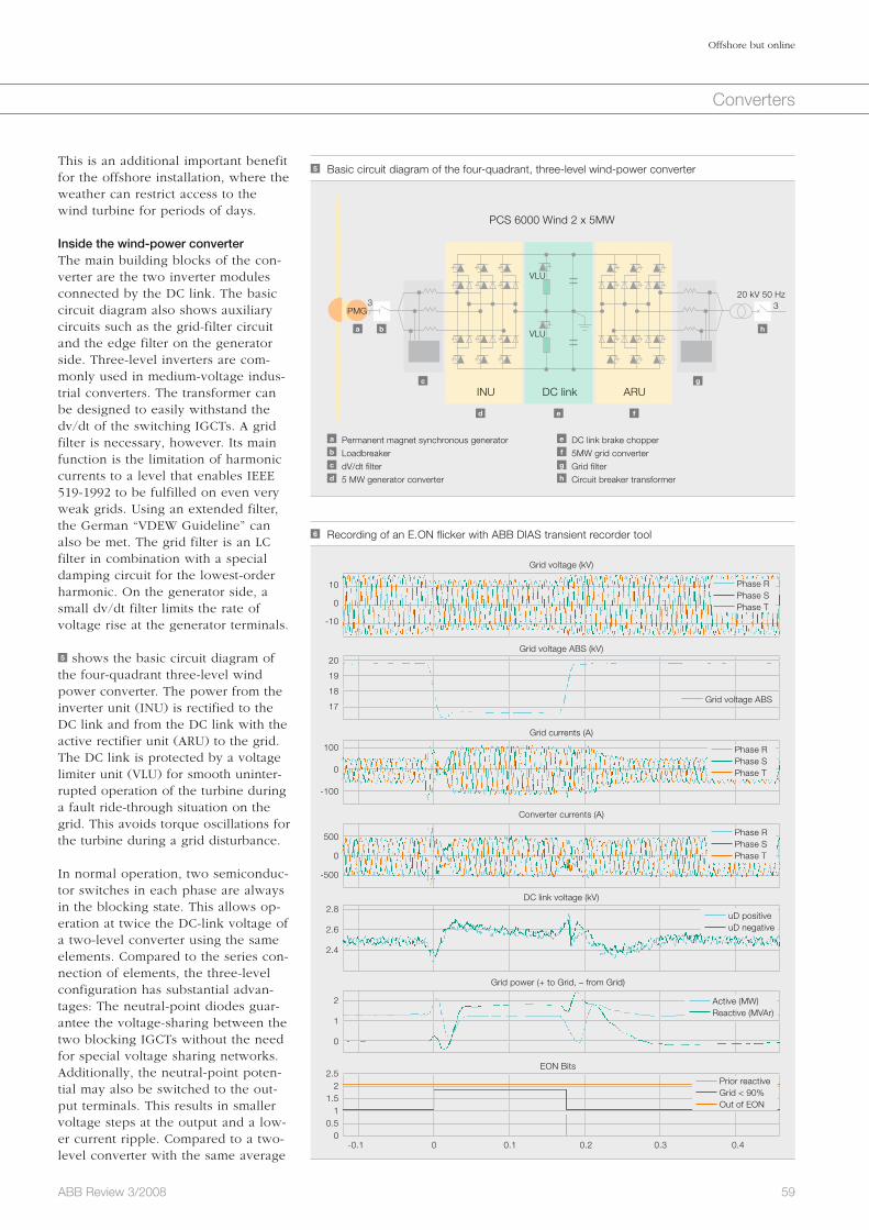
59ABB Review 3/2008
Offshore but online
Converters
This is an additional important benefit for the offshore installation, where the weather can restrict access to the wind turbine for periods of days.
Inside the wind-power converterThe main building blocks of the con-verter are the two inverter modules connected by the DC link. The basic circuit diagram also shows auxiliary circuits such as the grid-filter circuit and the edge filter on the generator side. Three-level inverters are com-monly used in medium-voltage indus-trial converters. The transformer can be designed to easily withstand the dv/dt of the switching IGCTs. A grid filter is necessary, however. Its main function is the limitation of harmonic currents to a level that enables IEEE 519-1992 to be fulfilled on even very weak grids. Using an extended filter, the German “VDEW Guideline” can also be met. The grid filter is an LC filter in combination with a special damping circuit for the lowest-order harmonic. On the generator side, a small dv/dt filter limits the rate of voltage rise at the generator terminals.
5 shows the basic circuit diagram of the four-quadrant three-level wind power converter. The power from the inverter unit (INU) is rectified to the DC link and from the DC link with the active rectifier unit (ARU) to the grid. The DC link is protected by a voltage limiter unit (VLU) for smooth uninter-rupted operation of the turbine during a fault ride-through situation on the grid. This avoids torque oscillations for the turbine during a grid disturbance.
In normal operation, two semiconduc-tor switches in each phase are always in the blocking state. This allows op-eration at twice the DC-link voltage of a two-level converter using the same elements. Compared to the series con-nection of elements, the three-level configuration has substantial advan-tages: The neutral-point diodes guar-antee the voltage-sharing between the two blocking IGCTs without the need for special voltage sharing networks. Additionally, the neutral-point poten-tial may also be switched to the out-put terminals. This results in smaller voltage steps at the output and a low-er current ripple. Compared to a two-level converter with the same average
5 Basic circuit diagram of the four-quadrant, three-level wind-power converter
PCS 6000 Wind 2 x 5MW
INU DC link
a Permanent magnet synchronous generatorb Loadbreakerc dV/dt filterd 5 MW generator converter
e DC link brake chopperf 5MW grid converterg Grid filterh Circuit breaker transformer
3 320 kV 50 Hz
PMG
+
+
+
+
+
+
+ +
+
+
+
+
+
+
+
+
+
++
+
+
+
ARU
+ +
VLU
VLU
+
+
a b h
c g
d e f
6 Recording of an E.ON flicker with ABB DIAS transient recorder tool
-0.1 0 0.1 0.2 0.3 0.4
Grid voltage (kV)
Grid voltage ABS (kV)
Grid currents (A)
Converter currents (A)
EON Bits
10
0
-10
100
0
-100
500
0
-500
2.8
2.6
2.4
2
1
0
2.52
1.51
0.50
20
19
18
17
Phase R Phase S Phase T
Grid voltage ABS
Phase R Phase S Phase T
Phase R Phase S Phase T
uD positive uD negative
Active (MW) Reactive (MVAr)
Prior reactive Grid < 90% Out of EON
DC link voltage (kV)
Grid power (+ to Grid, – from Grid)
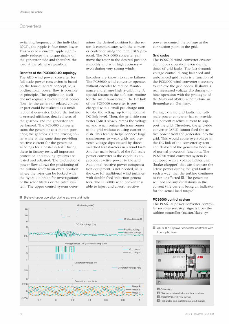
60 ABB Review 3/2008
Offshore but online
Converters
power to control the voltage at the connection point to the grid.
Grid codesThe PCS6000 wind converter ensures continuous operation even during times of grid faults. The fast dynamic voltage control during balanced and unbalanced grid faults is a function of the PCS6000 wind converter necessary to achieve the grid codes. 6 shows a real measured voltage dip during tur-bine operation with the prototype of the Multibrid M5000 wind turbine in Bremerhaven, Germany.
During extreme grid faults, the full-scale power converter has to provide 100 percent reactive current to sup-port the grid. Therefore, the grid-side converter (ARU) cannot feed the ac-tive power from the generator into the grid. This would cause overvoltage in the DC link of the converter system and de-load of the generator because of normal protection functions. The PCS6000 wind converter system is equipped with a voltage limiter unit (brake chopper) that can dissipate the active power during the grid fault in such a way, that the turbine continues to run unaffected 7 . The generator will not see any oscillations in the current (the current being an indicator for the actual load torque).
PCS6000 control system The PCS6000 power converter control-ler receives run/stop signals from the turbine controller (master/slave sys-
mines the desired position for the ro-tor. It communicates with the convert-er controller using the PROFIBUS pro-tocol. The PCS 6000 converter can move the rotor to the desired position smoothly and with high accuracy – even during very strong winds.
Encoders are known to cause failures. The PCS6000 wind converter operates without encoder to reduce mainte-nance and ensure high availability. A special feature is the soft-start routine for the main transformer. The DC link of the PCS6000 converter is pre-charged with a small pre-charge unit to take the voltage up to the nominal DC link level. Then, the grid side con-verter (ARU) slowly ramps the voltage up and synchronizes the transformer to the grid without causing current in-rush. This feature helps connect large transformers to weak grids and pre-vents voltage dips caused by direct switched transformers in a wind farm. Another main benefit of the full scale power converter is the capability to provide reactive power to the grid. Additional reactive power compensa-tion equipment is not needed, as is the case for traditional wind turbines with double feed induction genera-tors. The PCS6000 wind converter is able to inject and absorb reactive
switching frequency of the individual IGCTs, the ripple is four times lower. This very low current ripple signifi-cantly reduces the torque ripple on the generator side and therefore the load at the planetary gearbox.
Benefits of the PCS6000 4Q-topologyThe ABB wind power converter for full-scale power conversion is based on the four-quadrant concept, ie, a bi-directional power flow is possible in principle. The application itself doesn’t require a bi-directional power flow, ie, the generator related convert-er part could be realized as a unidi-rectional converter. Before the turbine is erected offshore, detailed tests of the gearbox and the generator are performed. The PCS6000 converter starts the generator as a motor, pow-ering the gearbox via the driving col-lar while at the same time providing reactive current for the generator windings for a heat-run test. During these in-factory tests, all important protection and cooling systems are tested and adjusted. The bi-directional power flow allows the positioning of the turbine rotor to an exact position where the rotor can be locked with the hydraulic brake for investigations of the rotor blades or the pitch sys-tem. The upper control system deter-
8 AC 800PEC power converter controller with fiber-optic links
a Cable ductb Fiber optic cables to/from optical modulesc AC 800PEC controller moduled Fast analog and digital input/output module
a
a
b
b
c
7 Brake chopper operation during extreme grid faults
Grid voltage (kV)
2000
0
-2000
4
3
2
20
10
0
3
2.5
3.5
3
-0.2 0 0.2 0.4 0.6 0.8 1
Grid voltage ABS
Generator voltage ABS
Positive voltage Negative voltage
VLU pos on VLU neg on
Phase R Phase S Phase T
Generator voltage (kV)
Generator currents (A)
Voltage limitier unit (VLU) switching state
DC link voltage (kV)

61ABB Review 3/2008
Offshore but online
Converters
density. Turbines in the range of 7 to 10 MW are expected in the future. For such wind farms, the re-quirements on the control of the turbines are different from the traditional arrange-ments. Furthermore, today’s wind power plants are usu-ally operated to feed as much energy as possible to the grid, even if there is just a gusty wind. The future tur-bines on large wind farms face new control require-ments. The offshore farm is seen as a large power gener-ation plant. In case of a grid-frequency drop for ex-
ample, the turbines have to maintain the power level to support the grid. A further requirement might be to limit the generated power to a level below the actual maximum level. Another important demand is that the turbine must stay in operation when reclosing operations are performed, as may happen when short-circuit problems occur in the grid.
ABB has successfully applied reliable and efficient medium-voltage convert-er technology to wind-power applica-tions.
The combination of powerful hard-ware and flexible control topology, supported by enhanced simulation facilities, is best suited to serve the wind power industry and to integrate even the largest wind turbines into grids with demanding connection re-quirements. If future turbines demand higher power, ABB has already the medium power converters for up to 14 MVA.
Markus Eichler
ABB Automation Products
Turgi, Switzerland
the process. In case of a problem, ABB service personnel are able to provide quality remote support to lo-cal service teams. The power convert-er control system AC800 PEC records all important signals and the status of the converter along with a timestamp during a fault. ABB personnel are able to analyze this with the built-in tran-sient recorder, which remotely records events and provides direct guidance to the personnel on site. Additionally, a simple human-machine interface (HMI) is available from remote loca-tions to give a quick overview of the PCS6000 wind converter. The system can automatically send e-mails with attached failure reports to ABB or the customer’s service teams. 9 shows an overview of the world-wide remote monitoring and diagnostic tools.
Turbines of up to 5 MW are already in series production, and turbines with higher power levels are either under develop-ment or at the prototype stage.
The next generation of turbinesTurbines of up to 5 MW are already in series production, and turbines with higher power levels are either under development or at the prototype stage. Most turbines of the next gener-ation are expected to be deployed in large wind-farms, situated either off-shore or in areas with low population
tem) using a digital link via PROFIBUS. Torque commands to the permanent-magnet syn-chronous generator (PMSG) are based on speed measure-ments with an update rate of at least 10 ms. A serial link connects the standard indus-trial programmable logic con-troller (PLC) master controller to the converter controller AC800 PEC 8 .
The active rectifier (ARU) must be able to operate the machine at maximum torque per ampere over the power curve until the voltage at the machine terminals reaches the limit of the active rectifier. From this point it must limit terminal voltage while the machine continues up the power curve. The inverter (INU) pro-vides real power to the grid while regulating the DC voltage. In order to meet these objectives, a field-oriented control strategy is proposed without the use of rotor-position sensors. The sensorless algorithm is based on a phase-locked loop (PLL), which syn-chronizes the internal/back EMF (elec-tromagnetic force) of the generator in proper phase and frequency to the permanent magnet flux. The feedback quantities for control are the genera-tor currents and the control outputs (to the modulator) are three phase references for the stator terminal volt-age. The power supply for the control system and all important I/O boards are protected by an uninterruptible DC power supply in case of auxiliary power supply loss. The PCS6000 con-verter control is prepared for long blackouts. The AC800 PEC control sys-tem detects condensation after a long power loss and starts an anti conden-sation routine before the turbine will be restarted.
Maintenance and serviceThe most important qualities of a power converter are that it should be reliable and easily maintained and serviced, even when located in a diffi-cult area offshore. The PCS6000 wind converter possesses approved soft-ware tools to enable remote service support for the converter. ABB’s Diag-nostic Information Analysis System (DIAS) is a smart tool for supervising
9 Remote access to the PCS6000 converter system via Internet
ModemService PC

62 ABB Review 3/2008
Converters
Wind power is one of the most important renewable ener-gy sources today. At the end of 2007, a total of 94 GW of wind power had been installed globally, of which only 1 GW was attributed to offshore installations. However, an increase of more than 1 GW per year is anticipated over the next five years, with a majority of that coming from about 100 planned offshore wind farms in Europe. Because many of these offshore power plants will be located quite a distance from the coast in an extremely hostile environment, their design, construction and opera-tion requires specialized skills.
Enabling the power of wind HVDC Light® for large-scale offshore wind integration Ambra Sannino, Peter Sandeberg, Lars Stendius, Raphael Görner
With over 20 years experience in the wind power industry, ABB has acquired a thorough understanding of both wind turbine applications and power systems. With this knowl-edge, it has developed a detailed design concept to con-nect the world’s largest and most remote offshore wind farm to the German grid using, for the first time in such an application, its innovative and environmentally friendly HVDC Light® transmission technology.
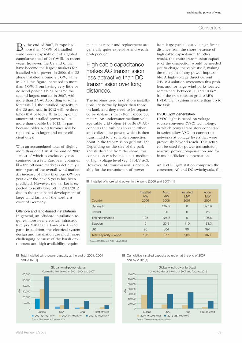
63ABB Review 3/2008
Enabling the power of wind
Converters
from large parks located a significant distance from the shore because of high cable capacitance. In other words, the entire transmission capaci-ty of the connection would be needed just to charge the cable itself, making the transport of any power impossi-ble. A high-voltage direct current (HVDC) solution overcomes this prob-lem, and for large wind parks located somewhere between 50 and 100 km from the transmission grid, ABB’s HVDC Light system is more than up to the task.
HVDC Light generalities HVDC Light is based on voltage source converter (VSC) technology, in which power transistors connected in series allow VSCs to connect to networks at voltage levels that were previously beyond reach. This setup can be used for power transmission, reactive power compensation and for harmonic/flicker compensation.
An HVDC Light station comprises the converter, AC and DC switchyards, fil-
ments, as repair and replacement are generally quite expensive and weath-er-dependent.
High cable capacitance makes AC transmission less actractive than DC transmission over long distances.
The turbines used in offshore installa-tions are normally larger than those on land, and they need to be separat-ed by distances that often exceed 500 meters. An underwater medium-volt-age cable grid (often 24 or 36 kV AC) connects the turbines to each other and collects the power, which is then transmitted to a suitable connection point in the transmission grid on land. Depending on the size of the park and its distance from the shore, this connection can be made at a medium- or high-voltage level (eg, 130 kV AC). However, AC transmission is not suit-able for the transmission of power
By the end of 2007, Europe had more than 56 GW of installed
wind power capacity out of a global cumulative total of 94 GW 2 . In recent years, however, the US and China have become the largest markets for installed wind power: in 2006, the US alone installed around 2.5 GW, while in 2007 this figure increased to more than 5 GW. From having very little or no wind power, China became the second largest market in 2007, with more than 3 GW. According to some forecasts [1], the installed capacity in the US and Asia in 2012 will be three times that of today 3 . In Europe, the amount of installed power will still more than double by 2012, in part because older wind turbines will be replaced with larger and more effi-cient ones.
With an accumulated total of slightly more than one GW at the end of 2007 – most of which is exclusively con-centrated in a few European countries 1 – the offshore market is definitely a minor part of the overall wind market. An increase of more than one GW per year over the next 5 years has been predicted. However, the market is ex-pected to really take off in 2011/2012 due to the anticipated development of large wind farms off the northern coast of Germany.
Offshore and land-based installationsIn general, an offshore installation re-quires more new electrical infrastruc-ture per MW than a land-based wind park. In addition, the electrical system design and installation are much more challenging because of the harsh envi-ronment and high availability require-
2 Total installed wind-power capacity at the end of 2001, 2004 and 2007 [1]
60,000
50,000
40,000
30,000
20,000
10,000
0
Cumulative MW by end of 2001, 2004 and 2007
Europe
Source: BTM Consult ApS – March 2008
USA Asia Rest of world
Global wind-power status
2001 (24,927 MW) 2004 (47,912 MW) 2007 (94,005 MW)
3 Cumulative installed capacity by region at the end of 2007 and by 2012 [1]
140,000
120,000
100,000
80,000
60,000
40,000
20,000
0
Cumulative MW by the end of 2007 and forecast 2012
Europe
Source: BTM Consult ApS – March 2008
USA Asia Rest of world
Global wind-power forecast
2007 (94,005 MW) 2012 (287,940 MW)
1 Installed offshore wind power in the world (2006 and 2007) [1]
Country
InstalledMW2006
Accu.MW2006
InstalledMW2007
Accu.MW2007
Denmark 0 397.9 0 397.9
Ireland 0 25 0 25
The Netherlands 108 126.8 0 126.8
Sweden 0 23.3 110 133.3
UK 90 304 90 394
Total capacity – world 198 877 200 1077
Source: BTM Consult ApS – March 2008
MW
MW
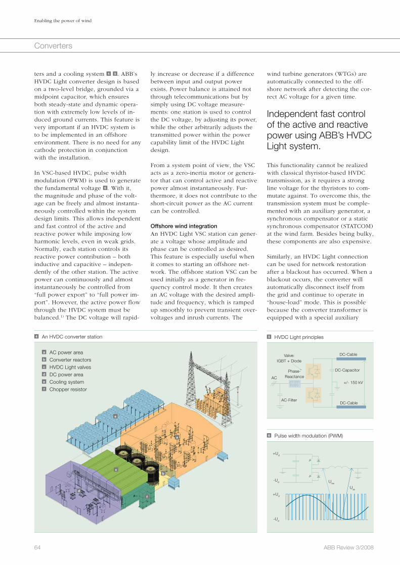
64 ABB Review 3/2008
Enabling the power of wind
Converters
wind turbine generators (WTGs) are automatically connected to the off-shore network after detecting the cor-rect AC voltage for a given time.
Independent fast control of the active and reactive power using ABB’s HVDC Light system.
This functionality cannot be realized with classical thyristor-based HVDC transmission, as it requires a strong line voltage for the thyristors to com-mutate against. To overcome this, the transmission system must be comple-mented with an auxiliary generator, a synchronous compensator or a static synchronous compensator (STATCOM) at the wind farm. Besides being bulky, these components are also expensive.
Similarly, an HVDC Light connection can be used for network restoration after a blackout has occurred. When a blackout occurs, the converter will auto matically disconnect itself from the grid and continue to operate in “house-load” mode. This is possible because the converter transformer is equipped with a special auxiliary
ly increase or decrease if a difference between input and output power exists. Power balance is attained not through telecommunications but by simply using DC voltage measure-ments: one station is used to control the DC voltage, by adjusting its power, while the other arbitrarily adjusts the transmitted power within the power capability limit of the HVDC Light design.
From a system point of view, the VSC acts as a zero-inertia motor or genera-tor that can control active and reactive power almost instantaneously. Fur-thermore, it does not contribute to the short-circuit power as the AC current can be controlled.
Offshore wind integrationAn HVDC Light VSC station can gener-ate a voltage whose amplitude and phase can be controlled as desired. This feature is especially useful when it comes to starting an offshore net-work. The offshore station VSC can be used initially as a generator in fre-quency control mode. It then creates an AC voltage with the desired ampli-tude and frequency, which is ramped up smoothly to prevent transient over-voltages and inrush currents. The
ters and a cooling system 4 5 . ABB’s HVDC Light converter design is based on a two-level bridge, grounded via a midpoint capacitor, which ensures both steady-state and dynamic opera-tion with extremely low levels of in-duced ground currents. This feature is very important if an HVDC system is to be implemented in an offshore environment. There is no need for any cathode protection in conjunction with the installation.
In VSC-based HVDC, pulse width modulation (PWM) is used to generate the fundamental voltage 6 . With it, the magnitude and phase of the volt-age can be freely and almost instanta-neously controlled within the system design limits. This allows independent and fast control of the active and reactive power while imposing low harmonic levels, even in weak grids. Normally, each station controls its reactive power contribution – both inductive and capacitive – indepen-dently of the other station. The active power can continuously and almost instantaneously be controlled from “full power export” to “full power im-port”. However, the active power flow through the HVDC system must be balanced.1) The DC voltage will rapid-
5 HVDC Light principles
Valve:IGBT + Diode
Phase-Reactance
AC-FilterDC-Cable
+/- 150 kV
DC-Cable
DC-Capacitor
AC
4 An HVDC converter station
a AC power areab Converter reactorsc HVDC Light valvesd DC power areae Cooling systemf Chopper resistor
a
bc
d
e
f
6 Pulse width modulation (PWM)
+Ud
+Ud
-Ud Usw
Uac
-Ud

65ABB Review 3/2008
Enabling the power of wind
Converters
stresses on the equipment in the wind turbines. This innovative solution will be supplied by ABB to Germany’s E.ON for what will be one of the larg-est offshore wind farms in the world.
NordE.ON 1: the first of its kind Germany’s first commercial offshore wind farm cluster, known as Bor-kum 2, will be situated approximately 130 km off its North Sea coast. This will be the first project in which off-shore wind power is connected to the grid using HVDC transmission. This modern, environmentally friendly technology, with its very low electro-magnetic fields, oil-free cables and compactly dimensioned converter sta-tions, cuts transmission losses by as much as 25 percent. The link, initially rated at 400 MW, will make an impor-tant contribution to Germany’s goal of increasing the share of renewable energies in power generation from its current level of 15 percent to between 25 and 30 percent by 2030. With a construction time of just 24 months, the network link is expected to be fully operational by September 2009.
The offshore platform is shown in 7 . Included in the AC power area are the transformers, circuit-breakers and har-monic filters. The HVDC Light trans-formers require only minor design modifications compared with standard power transformers of this size be-cause the harmonic filter almost com-pletely removes the electrical distur-bances from the converter. The con-verter reactors are used for filtering, and are also important in providing reactance to control the HVDC Light system. The alternating current is rec-tified using HVDC Light valves. For each phase, two containers are pro-vided, which house the IGBT valves,
can be “mirrored” to the wind farm grid without any significant delay.
Germany’s first commer-cial offshore wind farm will be connected to the grid using HVDC transmission.
If a reduction in the main grid voltage occurs, power transmission capability is reduced by a similar proportion because of the current limit of the inverting VSC. In a “standard” HVDC Light transmission system connecting two utility grids, a similar scenario is solved by instantaneously reducing the input power of the rectifying VSC through closed-loop current control. However, if, in a relatively weak wind farm grid, the input power of the rec-tifying VSC is quickly decreased, the wind farm bus voltage may increase significantly, causing the VSC and/or the wind turbines to eventually trip. One possible solution is to signal to the WTGs, via the grid voltage in the wind farm, that their output power should be reduced as quickly as pos-sible. However, due to the low DC capacitance value, the DC voltage may reach an unacceptably high level – such as 30 percent overvoltage at which the protection is set to trip – in just 5 to 10 ms if power transmission is interrupted. The WTGs must there-fore be able to detect this condition and reduce the output power within this time frame. An alternative is to employ a DC chopper4) to dissipate the excess energy that cannot be transmitted by the inverting VSC. There will then be no abrupt change in the output power from the wind turbines and the disturbance seen by them will be minimized.
Reducing the WTG power output is considered a relatively prompt and effective method, depending of course on the response of the WTGs to volt-age variations. A DC chopper, howev-er, offers a more robust solution in that its operation is the same regard-less of WTG type. Furthermore, an HVDC Light link, combined with a chopper, decouples the wind park grid from the fault and electrical tran-sients that occur in the main grid, thereby reducing the mechanical
power winding that supplies the con-verter station. If needed, the converter can also be started manually in black-start mode2).
Meeting strict grid codesAs the global share of installed wind power increases, the grid code re-quirements3) are becoming stricter. Most current grid codes set require-ments on so-called “fault ride through” or “low-voltage ride through,” mean-ing that a wind turbine or park must be able to survive sudden voltage dips down to 15 percent (and in some cases down to zero) of the nominal grid voltage for up to 150 ms. It is anticipated that frequency response requirements (ie, the wind farm power output should be increased as the grid frequency decreases and vice versa) will also be imposed. In a wind farm connected via an HVDC Light trans-mission system, frequency response control can be intro duced via a tele-communications link, which also transmits the instantaneous main grid frequency as well as other variables, between the onshore grid and the wind farm. Since the amplitude, fre-quency and phase of the voltage on the wind farm bus can be fully con-trolled by the VSC, the grid frequency
Footnotes1) This means the active power leaving the DC link
must be equal to the active power coming into
the DC link, minus the losses in the HVDC Light
system.2) The transmission link can be started from a
de-energized condition without power generation
from the wind turbines on the offshore side.3) These are the set of rules that regulate the inter-
connection of wind parks to the utility grid.4) A chopper is a resistor in the DC circuit with high
energy capability, which evacuates the surplus
energy during network faults when power trans-
mission is not possible.

66 ABB Review 3/2008
Enabling the power of wind
Converters
ment needed as DC grids are not in use today, with the exception of some specific applications.
Paving the way for other projectsThe design, construction and operation of a large scale power plant, positioned far out to sea in harsh environ-ments, requires significant skills and experience. Trans-porting the power to where it is needed demands the most up-to-date technology and inno vation, and a combina-tion of these comes in the form of HVDC Light. As a unique solution, it will soon lead to several gigawatts of offshore wind generation in Europe. It is hoped the valu-able lessons learned by the engineers working on this project will help to reduce the technical – and eventually the financial – risks faced by offshore wind farm develop-ers when it comes to choos-ing a suitable and reliable transmission system.
Ambra Sannino
ABB Corporate Research
Västerås, Sweden
Peter Sandeberg
Lars Stendius
ABB Power Systems
Ludvika, Sweden
Raphael Görner
ABB AG
Mannheim, Germany
design principles adopted for normal transmission system applications also apply for wind farm applications.
Transporting power to where it is needed demands the most up-to-date technology and innovation.
Similarly, the internal grid in a wind park could be designed for DC opera-tion at a suitable voltage level. Doing this leads to better utilization of the cables and lower losses per MW of generated power, mainly because reactive power is absent. The only drawback is the amount of develop-
DC capacitors and bushings. The sophisticated MACH 2TM protection, instrumentation and control system, with built-in redundancy, is locat-ed in two containers below the valves. In the DC power area, 128 km of marine cable and 74 km of land cable connect to the other HVDC Light converter station. A cooling system ensures that the HVDC Light valves operate at the correct tem-perature. The chopper resis-tor is used for fast active power reduction in the event of AC network faults.
Future prospects for HVDC-connected parks Significant improvements have been made over the years in performance of wind-conversion systems. These allow wind turbines to be connected to the trans-mission grid, safeguarding against surges in power gen-eration. However, some of the standard equipment in today’s wind turbines may now be redundant because HVDC Light can effectively decouple turbines from the transmission grid. By taking advantage of the controlla-bility offered by HVDC Light and its ability to optimize the electrical sys-tem in a wind park, it may be possible to utilize simpler (and therefore cheaper) and more robust wind con-version systems in the turbines.
Because HVDC Light can decouple the wind park from the grid, several pos-sibilities exist for the internal collec-tion grid in a wind park. An HVDC Light converter station normally fol-lows the AC voltage of the connected grids. The magnitude and frequency of this voltage are determined by the control systems in the generating sta-tions. However, the offshore converter station could also be used to optimize wind power production by controlling the grid frequency and voltage to a reference value set by a wind farm control system. No extra equipment is required to ensure variable frequency operation at one end and fixed grid frequency at the other. In general, the
7 An offshore platform for the “Borkum 2” wind farm cluster
a AC power areab Converter reactorsc HVDC Light valvesd DC power areae Cooling system
a
b
c
de
References
[1] BTM Consult, World Market Update 2007, March 2008.
[2] Wensky, D., Hanson, J., Sandeberg, P., Grünbaum, R. (2006). FACTS and HVDC for grid connection of
large offshore wind farms. European Wind Energy Conference EWEC.
[3] Jones, P., Westman, B. (November 2007). From generation to grid. Renewable Energy Focus.
[4] Stendius, L., Sandeberg, P. (2008). Large scale offshore wind power energy evacuation by HVDC Light.
European Wind Energy Conference EWEC.

Large control systems running com-plex industrial plants consist of mil-lions of lines of code and contain a number of third-party standard soft-ware modules for general aspects of process management. New versions of those modules are entering the market and operators of the control systems in a plant may install them to keep up to date. Operators sometimes also install other software not directly related to the control system; those changes in the software inventory of a plant may cause problems in its smooth operation.
Expedited problem solvingA new software diagnostics tool is keeping plant control systems on track Martin Olausson, Magnus Larsson, Jan Lagnelöv
Although ABB is not the root cause for those disturbances in the plant opera-tion system, it takes responsibility for the overall performance of the sys-tems it has installed. ABB’s service engineers are on standby 24 hours a day to support the operators in de-bugging failures in the customer’s software installations.
To find the source of a failure is a tedious process given the complexity of the manifold systems that must cooperate, and it may take weeks of intense interaction among the plant
operators to fix the problem. This is due to the fact that, for security rea-sons, the sensitive control systems are not directly connected to the Inter-net and thus do not allow for faster online analysis.
Determined to improve this less-than-ideal scenario, ABB has developed a set of intelligent software tools to speed up the failure removal from weeks to hours with minimum interac-tion of the plant operators.
67ABB Review 3/2008
Diagnosis and safety
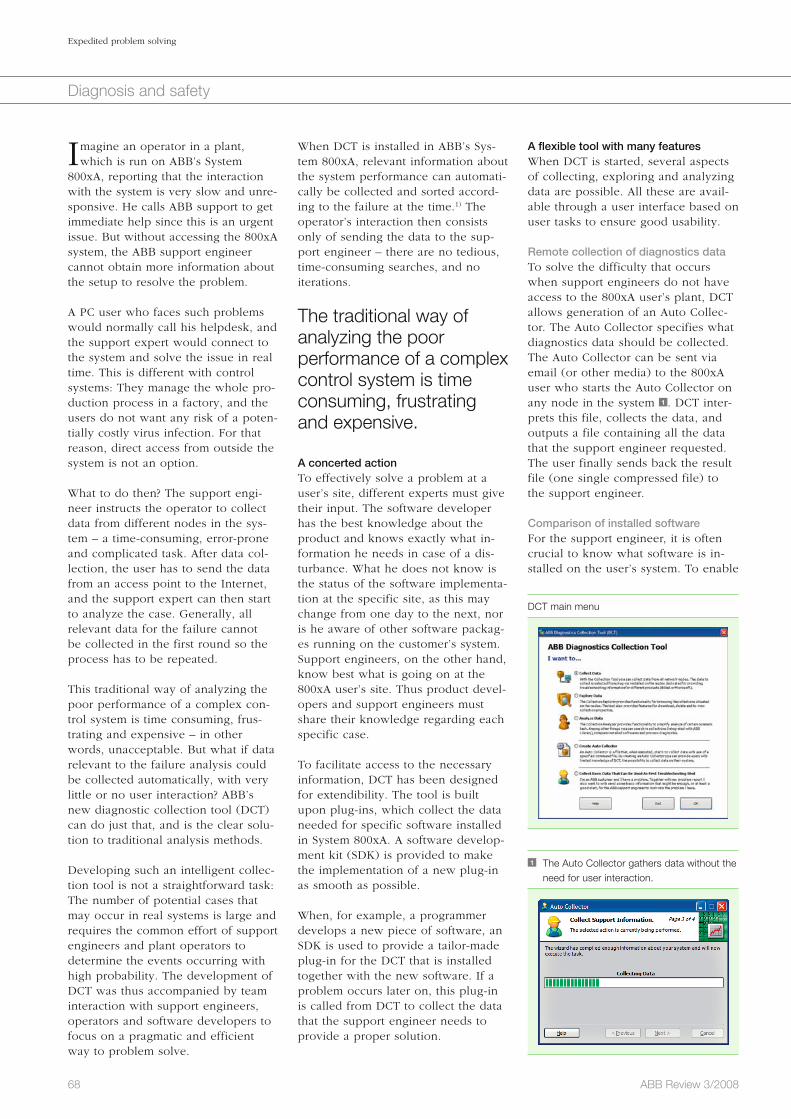
68 ABB Review 3/2008
Expedited problem solving
Diagnosis and safety
A flexible tool with many featuresWhen DCT is started, several aspects of collecting, exploring and analyzing data are possible. All these are avail-able through a user interface based on user tasks to ensure good usability.
Remote collection of diagnostics dataTo solve the difficulty that occurs when support engineers do not have access to the 800xA user’s plant, DCT allows generation of an Auto Collec-tor. The Auto Collector specifies what diagnostics data should be collected.The Auto Collector can be sent via email (or other media) to the 800xA user who starts the Auto Collector on any node in the system 1 . DCT inter-prets this file, collects the data, and outputs a file containing all the data that the support engineer requested. The user finally sends back the result file (one single compressed file) to the support engineer.
Comparison of installed softwareFor the support engineer, it is often crucial to know what software is in-stalled on the user’s system. To enable
When DCT is installed in ABB’s Sys-tem 800xA, relevant information about the system performance can automati-cally be collected and sorted accord-ing to the failure at the time.1) The operator’s interaction then consists only of sending the data to the sup-port engineer – there are no tedious, time-consuming searches, and no iterations.
The traditional way of analyzing the poor performance of a complex control system is time consuming, frustrating and expensive.
A concerted actionTo effectively solve a problem at a user’s site, different experts must give their input. The software developer has the best knowledge about the product and knows exactly what in-formation he needs in case of a dis-turbance. What he does not know is the status of the software implementa-tion at the specific site, as this may change from one day to the next, nor is he aware of other software packag-es running on the customer’s system. Support engineers, on the other hand, know best what is going on at the 800xA user’s site. Thus product devel-opers and support engineers must share their knowledge regarding each specific case.
To facilitate access to the necessary information, DCT has been designed for extendibility. The tool is built upon plug-ins, which collect the data needed for specific software installed in System 800xA. A software develop-ment kit (SDK) is provided to make the implementation of a new plug-in as smooth as possible.
When, for example, a programmer develops a new piece of software, an SDK is used to provide a tailor-made plug-in for the DCT that is installed together with the new software. If a problem occurs later on, this plug-in is called from DCT to collect the data that the support engineer needs to provide a proper solution.
Imagine an operator in a plant, which is run on ABB’s System
800xA, reporting that the interaction with the system is very slow and unre-sponsive. He calls ABB support to get immediate help since this is an urgent issue. But without accessing the 800xA system, the ABB support engineer cannot obtain more information about the setup to resolve the problem.
A PC user who faces such problems would normally call his helpdesk, and the support expert would connect to the system and solve the issue in real time. This is different with control systems: They manage the whole pro-duction process in a factory, and the users do not want any risk of a poten-tially costly virus infection. For that reason, direct access from outside the system is not an option.
What to do then? The support engi-neer instructs the operator to collect data from different nodes in the sys-tem – a time-consuming, error-prone and complicated task. After data col-lection, the user has to send the data from an access point to the Internet, and the support expert can then start to analyze the case. Generally, all relevant data for the failure cannot be collected in the first round so the process has to be repeated.
This traditional way of analyzing the poor performance of a complex con-trol system is time consuming, frus-trating and expensive – in other words, unacceptable. But what if data relevant to the failure analysis could be collected automatically, with very little or no user interaction? ABB’s new diagnostic collection tool (DCT) can do just that, and is the clear solu-tion to traditional analysis methods.
Developing such an intelligent collec-tion tool is not a straightforward task: The number of potential cases that may occur in real systems is large and requires the common effort of support engineers and plant operators to deter mine the events occurring with high probability. The development of DCT was thus accompanied by team interaction with support engineers, operators and software developers to focus on a pragmatic and efficient way to problem solve.
1 The Auto Collector gathers data without the need for user interaction.
DCT main menu
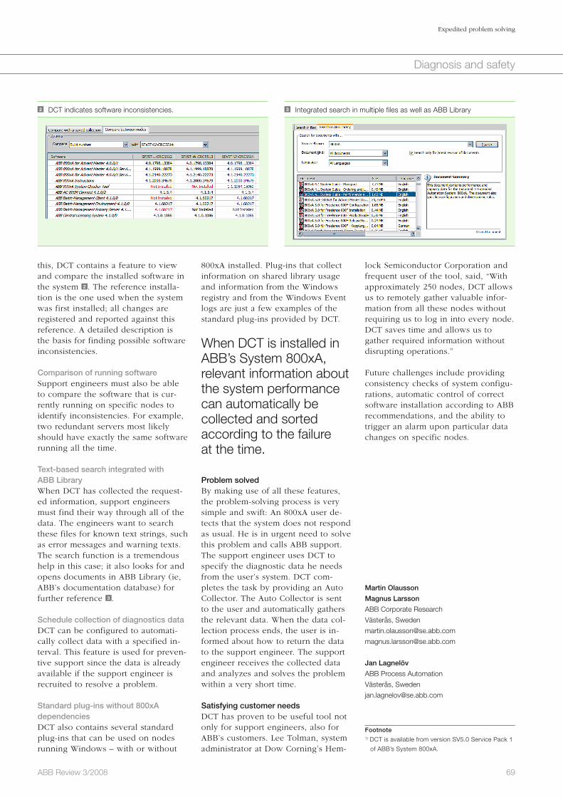
69ABB Review 3/2008
Expedited problem solving
Diagnosis and safety
lock Semiconductor Corporation and frequent user of the tool, said, “With approximately 250 nodes, DCT allows us to remotely gather valuable infor-mation from all these nodes without requiring us to log in into every node. DCT saves time and allows us to gather required information without disrupting operations.”
Future challenges include providing consistency checks of system configu-rations, automatic control of correct software installation according to ABB recommendations, and the ability to trigger an alarm upon particular data changes on specific nodes.
Martin Olausson
Magnus Larsson
ABB Corporate Research
Västerås, Sweden
Jan Lagnelöv
ABB Process Automation
Västerås, Sweden
Footnote1) DCT is available from version SV5.0 Service Pack 1
of ABB’s System 800xA.
800xA installed. Plug-ins that collect information on shared library usage and information from the Windows registry and from the Windows Event logs are just a few examples of the standard plug-ins provided by DCT.
When DCT is installed in ABB’s System 800xA, relevant information about the system performance can automatically be collected and sorted according to the failure at the time.
Problem solvedBy making use of all these features, the problem-solving process is very simple and swift: An 800xA user de-tects that the system does not respond as usual. He is in urgent need to solve this problem and calls ABB support. The support engineer uses DCT to specify the diagnostic data he needs from the user’s system. DCT com-pletes the task by providing an Auto Collector. The Auto Collector is sent to the user and automatically gathers the relevant data. When the data col-lection process ends, the user is in-formed about how to return the data to the support engineer. The support engineer receives the collected data and analyzes and solves the problem within a very short time.
Satisfying customer needsDCT has proven to be useful tool not only for support engineers, also for ABB’s customers. Lee Tolman, system administrator at Dow Corning’s Hem-
this, DCT contains a feature to view and compare the installed software in the system 2 . The reference installa-tion is the one used when the system was first installed; all changes are registered and reported against this reference. A detailed description is the basis for finding possible software inconsistencies.
Comparison of running softwareSupport engineers must also be able to compare the software that is cur-rently running on specific nodes to identify inconsistencies. For example, two redundant servers most likely should have exactly the same software running all the time.
Text-based search integrated with ABB Library When DCT has collected the request-ed information, support engineers must find their way through all of the data. The engineers want to search these files for known text strings, such as error messages and warning texts. The search function is a tremendous help in this case; it also looks for and opens documents in ABB Library (ie, ABB’s documentation database) for further reference 3 .
Schedule collection of diagnostics dataDCT can be configured to automati-cally collect data with a specified in-terval. This feature is used for preven-tive support since the data is already available if the support engineer is recruited to resolve a problem.
Standard plug-ins without 800xA dependenciesDCT also contains several standard plug-ins that can be used on nodes running Windows – with or without
2 DCT indicates software inconsistencies. 3 Integrated search in multiple files as well as ABB Library
70 ABB Review 3/2008
No airport can safely operate today without a radar control system. These systems send out radar pulses of high intensity and detect airplanes by the reflected signals. A crucial element in all these radar systems is the device that emits high-power pulses. Tradi-tionally, pulses are generated with help of electron tubes like thyratrons. The era of electron tubes, also used in several other applications, is coming to an end as ABB has recently devel-oped high-power, fully solid-state switches for pulsed applications.
This advanced technology, boasting significant benefits for the user, has become the main component for the modernization of airport radar sys-tems in the United States. The fact that 300 systems have been ordered to equip all 132 civil airports in the United States underlines the strong market for this groundbreaking tech-nology.
Safe landing with pulsed power ABB semiconductor switches are improving radar control systems at US airports Adriaan Welleman
Diagnosis and safety
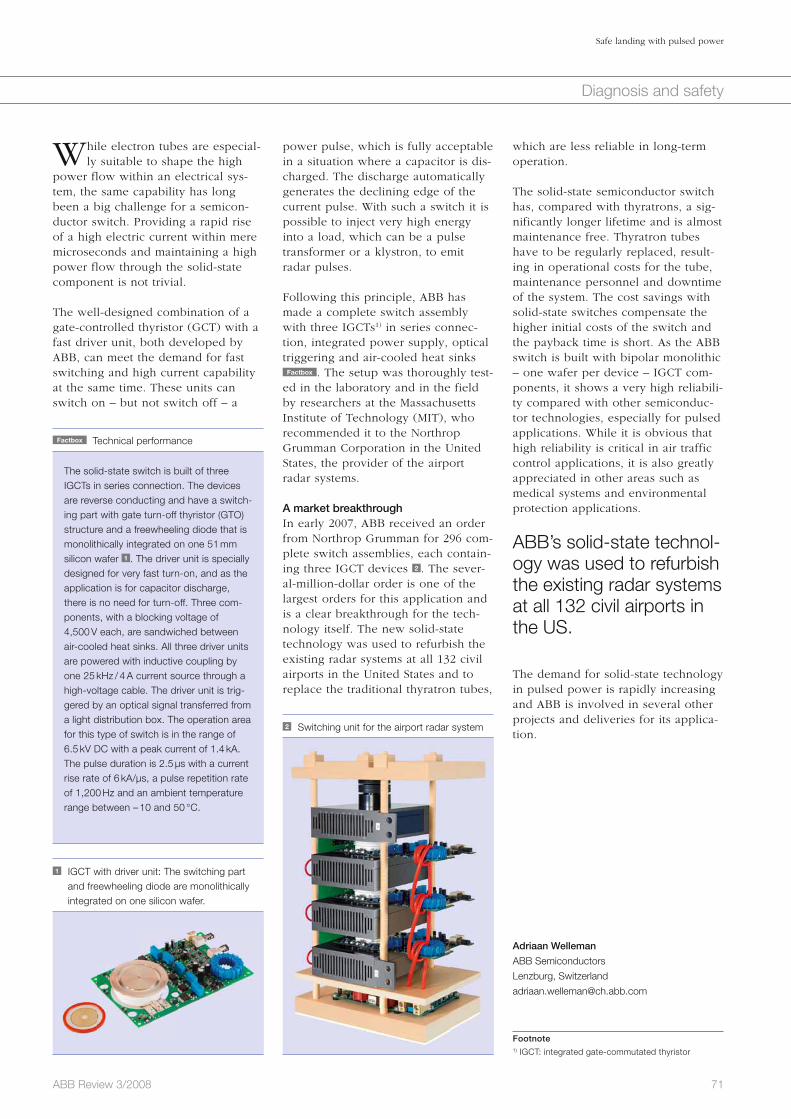
Safe landing with pulsed power
71ABB Review 3/2008
Diagnosis and safety
which are less reliable in long-term operation.
The solid-state semiconductor switch has, compared with thyratrons, a sig-nificantly longer lifetime and is almost maintenance free. Thyratron tubes have to be regularly replaced, result-ing in operational costs for the tube, maintenance personnel and downtime of the system. The cost savings with solid-state switches compensate the higher initial costs of the switch and the payback time is short. As the ABB switch is built with bipolar monolithic – one wafer per device – IGCT com-ponents, it shows a very high reliabili-ty compared with other semiconduc-tor technologies, especially for pulsed applications. While it is obvious that high reliability is critical in air traffic control applications, it is also greatly appreciated in other areas such as medical systems and environmental protection applications.
ABB’s solid-state technol-ogy was used to refurbish the existing radar systems at all 132 civil airports in the US.
The demand for solid-state technology in pulsed power is rapidly increasing and ABB is involved in several other projects and deliveries for its applica-tion.
Adriaan Welleman
ABB Semiconductors
Lenzburg, Switzerland
Footnote1) IGCT: integrated gate-commutated thyristor
While electron tubes are especial-ly suitable to shape the high
power flow within an electrical sys-tem, the same capability has long been a big challenge for a semicon-ductor switch. Providing a rapid rise of a high electric current within mere microseconds and maintaining a high power flow through the solid-state component is not trivial.
The well-designed combination of a gate-controlled thyristor (GCT) with a fast driver unit, both developed by ABB, can meet the demand for fast switching and high current capability at the same time. These units can switch on – but not switch off – a
2 Switching unit for the airport radar system
Factbox Technical performance
The solid-state switch is built of three IGCTs in series connection. The devices are reverse conducting and have a switch-ing part with gate turn-off thyristor (GTO) structure and a freewheeling diode that is monolithically integrated on one 51 mm silicon wafer 1 . The driver unit is specially designed for very fast turn-on, and as the application is for capacitor discharge, there is no need for turn-off. Three com-ponents, with a blocking voltage of 4,500 V each, are sandwiched between air-cooled heat sinks. All three driver units are powered with inductive coupling by one 25 kHz / 4 A current source through a high-voltage cable. The driver unit is trig-gered by an optical signal transferred from a light distribution box. The operation area for this type of switch is in the range of 6.5 kV DC with a peak current of 1.4 kA. The pulse duration is 2.5 µs with a current rise rate of 6 kA/µs, a pulse repetition rate of 1,200 Hz and an ambient temperature range between – 10 and 50 °C.
1 IGCT with driver unit: The switching part and freewheeling diode are monolithically
integrated on one silicon wafer.
power pulse, which is fully acceptable in a situation where a capacitor is dis-charged. The discharge automatically generates the declining edge of the current pulse. With such a switch it is possible to inject very high energy into a load, which can be a pulse transformer or a klystron, to emit radar pulses.
Following this principle, ABB has made a complete switch assembly with three IGCTs1) in series connec-tion, integrated power supply, optical triggering and air-cooled heat sinks
Factbox . The setup was thoroughly test-ed in the laboratory and in the field by researchers at the Massachusetts Institute of Technology (MIT), who recommended it to the Northrop Grumman Corporation in the United States, the provider of the airport radar systems.
A market breakthroughIn early 2007, ABB received an order from Northrop Grumman for 296 com-plete switch assemblies, each contain-ing three IGCT devices 2 . The sever-al-million-dollar order is one of the largest orders for this application and is a clear breakthrough for the tech-nology itself. The new solid-state technology was used to refurbish the existing radar systems at all 132 civil airports in the United States and to replace the traditional thyratron tubes,
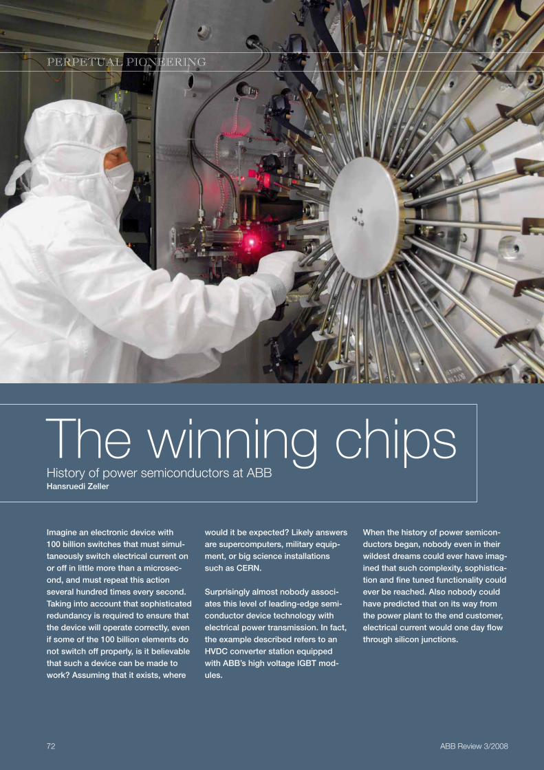
Imagine an electronic device with 100 billion switches that must simul-taneously switch electrical current on or off in little more than a microsec-ond, and must repeat this action several hundred times every second. Taking into account that sophisticated redundancy is required to ensure that the device will operate correctly, even if some of the 100 billion elements do not switch off properly, is it believable that such a device can be made to work? Assuming that it exists, where
The winning chipsHistory of power semiconductors at ABBHansruedi Zeller
72 ABB Review 3/2008
PERPETUAL PIONEERING
would it be expected? Likely answers are supercomputers, military equip-ment, or big science installations such as CERN.
Surprisingly almost nobody associ-ates this level of leading-edge semi-conductor device technology with electrical power transmission. In fact, the example described refers to an HVDC converter station equipped with ABB’s high voltage IGBT mod-ules.
When the history of power semicon-ductors began, nobody even in their wildest dreams could ever have imag-ined that such complexity, sophistica-tion and fine tuned functionality could ever be reached. Also nobody could have predicted that on its way from the power plant to the end customer, electrical current would one day flow through silicon junctions.
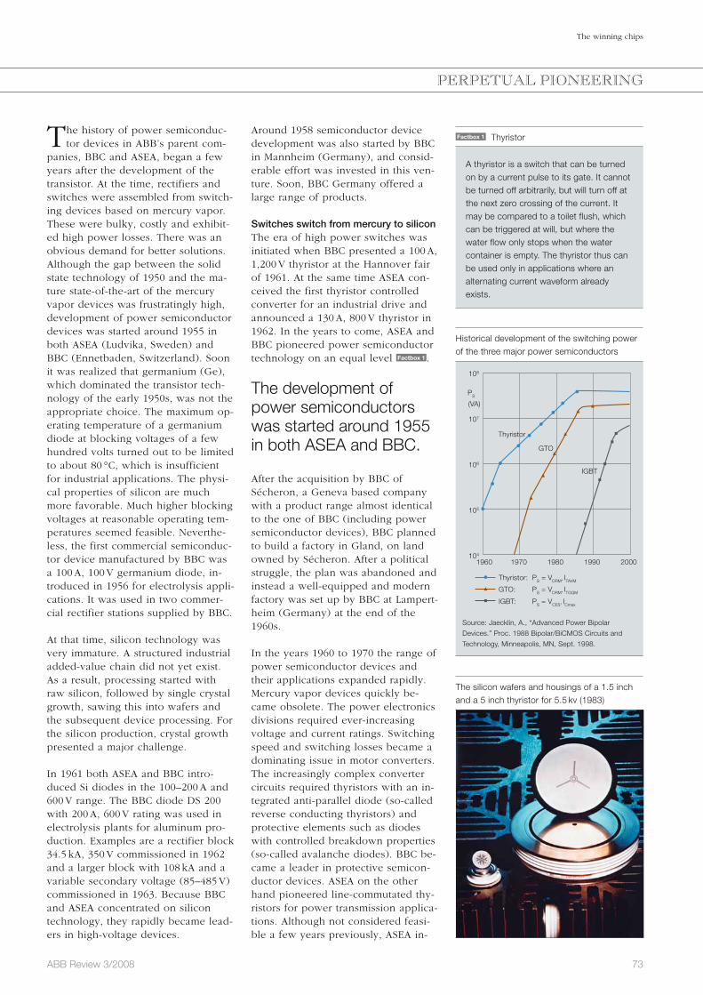
73ABB Review 3/2008
The winning chips
Around 1958 semiconductor device development was also started by BBC in Mannheim (Germany), and consid-erable effort was invested in this ven-ture. Soon, BBC Germany offered a large range of products.
Switches switch from mercury to siliconThe era of high power switches was initiated when BBC presented a 100 A, 1,200 V thyristor at the Hannover fair of 1961. At the same time ASEA con-ceived the first thyristor controlled converter for an industrial drive and announced a 130 A, 800 V thyristor in 1962. In the years to come, ASEA and BBC pioneered power semiconductor technology on an equal level Factbox 1 .
The development of power semiconductors was started around 1955 in both ASEA and BBC.
After the acquisition by BBC of Sécheron, a Geneva based company with a product range almost identical to the one of BBC (including power semiconductor devices), BBC planned to build a factory in Gland, on land owned by Sécheron. After a political struggle, the plan was abandoned and instead a well-equipped and modern factory was set up by BBC at Lampert-heim (Germany) at the end of the 1960s.
In the years 1960 to 1970 the range of power semiconductor devices and their applications expanded rapidly. Mercury vapor devices quickly be-came obsolete. The power electronics divisions required ever-increasing voltage and current ratings. Switching speed and switching losses became a dominating issue in motor converters. The increasingly complex converter circuits required thyristors with an in-tegrated anti-parallel diode (so-called reverse conducting thyristors) and protective elements such as diodes with controlled breakdown properties (so-called avalanche diodes). BBC be-came a leader in protective semicon-ductor devices. ASEA on the other hand pioneered line-commutated thy-ristors for power transmission applica-tions. Although not considered feasi-ble a few years previously, ASEA in-
The history of power semiconduc-tor devices in ABB’s parent com-
panies, BBC and ASEA, began a few years after the development of the transistor. At the time, rectifiers and switches were assembled from switch-ing devices based on mercury vapor. These were bulky, costly and exhibit-ed high power losses. There was an obvious demand for better solutions. Although the gap between the solid state technology of 1950 and the ma-ture state-of-the-art of the mercury vapor devices was frustratingly high, development of power semiconductor devices was started around 1955 in both ASEA (Ludvika, Sweden) and BBC (Ennetbaden, Switzerland). Soon it was realized that germanium (Ge), which dominated the transistor tech-nology of the early 1950s, was not the appropriate choice. The maximum op-erating temperature of a germanium diode at blocking voltages of a few hundred volts turned out to be limited to about 80 °C, which is insufficient for industrial applications. The physi-cal properties of silicon are much more favorable. Much higher blocking voltages at reasonable operating tem-peratures seemed feasible. Neverthe-less, the first commercial semiconduc-tor device manufactured by BBC was a 100 A, 100 V germanium diode, in-troduced in 1956 for electrolysis appli-cations. It was used in two commer-cial rectifier stations supplied by BBC.
At that time, silicon technology was very immature. A structured industrial added-value chain did not yet exist. As a result, processing started with raw silicon, followed by single crystal growth, sawing this into wafers and the subsequent device processing. For the silicon production, crystal growth presented a major challenge.
In 1961 both ASEA and BBC intro-duced Si diodes in the 100–200 A and 600 V range. The BBC diode DS 200 with 200 A, 600 V rating was used in electrolysis plants for aluminum pro-duction. Examples are a rectifier block 34.5 kA, 350 V commissioned in 1962 and a larger block with 108 kA and a variable secondary voltage (85–485 V) commissioned in 1963. Because BBC and ASEA concentrated on silicon technology, they rapidly became lead-ers in high-voltage devices.
PERPETUAL PIONEERING
Factbox 1 Thyristor
A thyristor is a switch that can be turned on by a current pulse to its gate. It cannot be turned off arbitrarily, but will turn off at the next zero crossing of the current. It may be compared to a toilet flush, which can be triggered at will, but where the water flow only stops when the water container is empty. The thyristor thus can be used only in applications where an alternating current waveform already exists.
The silicon wafers and housings of a 1.5 inch and a 5 inch thyristor for 5.5 kv (1983)
Historical development of the switching power of the three major power semiconductors
108
107
106
105
104
1960 1970 1980 1990 2000
PS
(VA)
Thyristor
Thyristor: PS = VDRM* ITAVM
GTO: PS = VDRM* ITGQM
IGBT: PS = VCES* ICmax
GTO
IGBT
Source: Jaecklin, A., “Advanced Power Bipolar
Devices.” Proc. 1988 Bipolar/BiCMOS Circuits and
Technology, Minneapolis, MN, Sept. 1998.
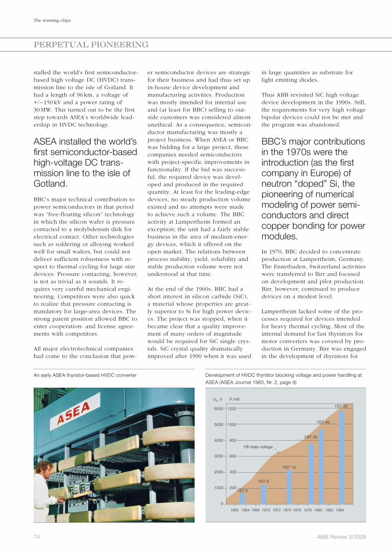
74 ABB Review 3/2008
The winning chips
in large quantities as substrate for light emitting diodes.
Thus ABB revisited SiC high voltage device development in the 1990s. Still, the requirements for very high voltage bipolar devices could not be met and the program was abandoned.
BBC’s major contributions in the 1970s were the introduction (as the first company in Europe) of neutron “doped” Si, the pioneering of numerical modeling of power semi-conductors and direct copper bonding for power modules.
In 1970, BBC decided to concentrate production at Lampertheim, Germany. The Ennetbaden, Switzerland activities were transferred to Birr and focused on development and pilot production. Birr, however, continued to produce devices on a modest level.
Lampertheim lacked some of the pro-cesses required for devices intended for heavy thermal cycling. Most of the internal demand for fast thyristors for motor converters was covered by pro-duction in Germany. Birr was engaged in the development of thyristors for
er semiconductor devices are strategic for their business and had thus set up in-house device development and manufacturing activities. Production was mostly intended for internal use and (at least for BBC) selling to out-side customers was considered almost unethical. As a consequence, semicon-ductor manufacturing was mostly a project business. When ASEA or BBC was bidding for a large project, these companies needed semiconductors with project-specific improvements in functionality. If the bid was success-ful, the required device was devel-oped and produced in the required quantity. At least for the leading-edge devices, no steady production volume existed and no attempts were made to achieve such a volume. The BBC activity at Lampertheim formed an exception; the unit had a fairly stable business in the area of medium-ener-gy devices, which it offered on the open market. The relations between process stability, yield, reliability and stable production volume were not understood at that time.
At the end of the 1960s, BBC had a short interest in silicon carbide (SiC), a material whose properties are great-ly superior to Si for high power devic-es. The project was stopped, when it became clear that a quality improve-ment of many orders of magnitude would be required for SiC single crys-tals. SiC crystal quality dramatically improved after 1990 when it was used
stalled the world’s first semiconductor-based high voltage DC (HVDC) trans-mission line to the isle of Gotland. It had a length of 96 km, a voltage of +/– 150 kV and a power rating of 30 MW. This turned out to be the first step towards ASEA’s worldwide lead-ership in HVDC technology.
ASEA installed the world’s first semiconductor-based high-voltage DC trans-mission line to the isle of Gotland.
BBC’s major technical contribution to power semiconductors in that period was “free-floating silicon” technology in which the silicon wafer is pressure contacted to a molybdenum disk for electrical contact. Other technologies such as soldering or alloying worked well for small wafers, but could not deliver sufficient robustness with re-spect to thermal cycling for large size devices. Pressure contacting, however, is not as trivial as it sounds. It re-quires very careful mechanical engi-neering. Competitors were also quick to realize that pressure contacting is mandatory for large-area devices. The strong patent position allowed BBC to enter cooperation- and license agree-ments with competitors.
All major electrotechnical companies had come to the conclusion that pow-
PERPETUAL PIONEERING
An early ASEA thyristor-based HVDC converter Development of HVDC thyristor blocking voltage and power handling at ASEA (ASEA Journal 1983, Nr. 2, page 9)
YST 506000
5000
4000
3000
2000
1000
0
YST 45
YST 35
YST 14
YST 8
YST 5
1962 1964 1968 1970 1972 1974 1976 1978 1980 1982 1984
Off-state voltage
UD, V P, kW
1200
1000
800
600
400
200

75ABB Review 3/2008
The winning chips
ASEA made a brief excursion into light-triggered thyristors, but conclud-ed that light triggering offered no advantage compared to electrical trig-gering.
The power electronics divisions of ASEA and BBC were very reluctant to introduce gate turn-off thyristor (GTO) technology in their motor con-verters. They kept using increasingly sophisticated fast thyristors. As a re-sult, GTO device manufacturing was lagging behind the Japanese competi-tion. In 1985 BBC entered a technolo-gy transfer agreement with Toshiba to accelerate the introduction of GTOs. As a latecomer, ABB became world leader in GTO manufacturing in the 1990s and has kept this position Factbox 2 .
ABB consolidates its resourcesAfter the merger of ASEA and BBC in 1987, it became clear that the ever-increasing technology and business challenges could not be met by three separate production locations. It was thus decided to sell the Lampertheim activity to IXYS, a US company. In 1991 the Västerås activities were closed and semiconductor production within ABB was concentrated at Lenz-burg, Switzerland. The newly formed company, ABB Semiconductors rapid-ly and successfully expanded its activ-ities into the open market. Manage-ment with solid business and technol-ogy expertise was brought in. Andy Nilarp, who started his professional carrier at ASEA and later became a top
high voltage DC transmission (HVDC) applications. In 1968 BBC entered the HVDC world in a consortium with AEG and Siemens. The part-nership resulted in two major contracts: Cabora Bassa, Mo-zambique (1,920 MW, cable length 1,450 km, operational 1977) and Nelson River, Can-ada (cable length 940 km, 900 MW operational 1978 and 2,000 MW operational 1985). The semiconductor volume was split equally among the partners. The BBC part of the devices was first produced in Birr and later in a modern new factory established in Lenzburg (Switzerland) in 1979.
BBC Corporate Research started a power semiconductor research and development activity in 1970. Its major contributions in the 1970s were the introduction (as the first company in Europe) of neutron “doped” Si, the pioneering of numerical modeling of power semiconductors and direct copper bonding for power modules. In neutron “doping” a single Si crystal is exposed to a flux of slow neutrons. These cause some Si nuclei to trans-form into phosphorus, which is a dopant. This results in a very homoge-neous dopant concentration. Direct copper bonding uses the fact that copper oxide forms a low melting point eutectic with copper and allows the bonding of copper electrodes directly onto ceramic substrates. Direct copper bonding became a significant competitive advantage for the BBC Lampertheim power module activities.
Today ABB is the only supplier in the world that can guarantee long-term survival of a failed module in series connection.
ASEA made impressive progress in thyristors for its HVDC business. Be-tween 1960 and 1980 the maximum blocking voltage and the maximum power handling per device increased approximately linearly in time from virtually zero before 1960 to 6,000 V and 600 kW, respectively in 1980.
PERPETUAL PIONEERING
Factbox 2 Gate turn-off thyristor (GTO)
The GTO is a switch similar to the thyris-tor. In contrast to the thyristor, a GTO can be turned off at any arbitrary point in the current waveform. Due to an inherent fila-mentary instability of the current distribu-tion during turn off, it requires a protection circuit (snubber).
Factbox Insulated-gate bipolar transistor (IGBT)
This is a bipolar transistor that obtains its gate current from a MOS channel. As long as extreme operating conditions are avoided, the device exhibits no instabilities and allows operation with no or minimum protective circuitry.
Factbox Integrated gate-commutated thyristor (IGCT)
This is basically a GTO in which the fila-mentary current instability is avoided by commuting the anode current from the cathode to an external capacitor during turn-off. A snubber (protective) circuit is not mandatory.
rank executive at Internation-al Rectifier Company (El Se-gundo CA, USA), proved to be a charismatic and enthusi-astic CEO. He pioneered the culture change from a fluctu-ating project business to a fine-tuned, high-volume pro-duction line with modern methods of process control.
As early as 1995, ABB Semi-conductors became a finalist in the European Quality Award and in 1996 earned the “Supplier of the Year Award” from General Electric Company, USA.
The focus on high-voltage thyristors and GTOs led to some curious situa-tions. For instance, when a last call for orders for a number of fast thyris-tors was sent to customers, a huge order came in for a device that had
Stud-mounted thyristors (1966)

76 ABB Review 3/2008
The winning chips
bipolar transistor) would be restricted to blocking voltages below 1,500 V. The MCT under devleopment at ABB Corporate Research in Dättwil re-quired a few IGBT cells to be turned on. It came as a big surprise when it was discovered that the 4.5 kV IGBT cells had favorable power losses. The MCT development was quickly can-celled and a program for high voltage IGBTs was initiated. Success came very fast. In 1992 the world’s first sample of a 4.5 kV, 600 A IGBT mod-ule was presented.
It was clear that MOS-controlled de-vices such as IGBTs could not be pro-duced in the Lenzburg facility. Neither the process equipment, nor the clean-room was suited for the production of the delicate MOS structures. It was thus decided to enter a co-operation with International Rectifier Company, El Segundo (California) to use the latter company’s production line. In 1994 the micro-laboratory at ABB Cor-porate Research Dättwil was closed, with key personnel being transferred to El Segundo.
External production of IGBTs was never considered to be the long term solution. In 1998 ABB opened a new factory at Lenzburg, Switzerland and the IGBT activities were shifted from the US back to Switzerland. This Lenzburg factory is the only factory in the world dedicated exclusively to IGBT manufacturing. Today ABB is the only supplier to offer the full product range of IGBTs and bipolar devices in the high voltage/high power range.
GTO and IGBT differ not only in the way switching is controlled. The GTO is a true switch and as such exhibits only two stable states, on and off. During turn-off it passes through a potentially destructive instability re-gime. To ensure safe switching, a net-work of protective devices, so called snubbers, is used. The IGBT is not a switch, but a transistor and does not exhibit instabilities during switching if operated inside design margins. Operation without a snubber circuit is possible. However, textbook wisdom says that a transistor (IGBT), in which charge carriers are injected only at one electrode has a higher on state
ry with cleanroom and state of the art processing capabilities in 1988. ASEA entered a co-operation with IXYS to gain access to MOS processing capa-bility.
To ensure safe switching, a network of protective devices, so-called snub-bers, is used. The IGBT is not a switch, but a tran-sistor and hence does not exhibit instabilities during switching if operated within design margins.
However, it was not clear what a high voltage MOS-controlled device would look like. A large number of novel device concepts were discussed in technical literature. Two concepts were pursued by ABB: One consisted of a large area, high voltage thyristor with an integrated MOS structure to improve the turn-off properties (so called QCT, Q-Control Thyristor). The second was an MCT (MOS-Controlled Thyristor), which is a turn-off device similar to a GTO. For fundamental reasons, both device concepts turned out to be unrealistic. The QCT had performance and yield issues and the MCT was stopped by intrinsic turn-off instability problems.
In 1990, it was the generally accepted belief that the IGBT (insulated-gate
never been ordered before and that had never got beyond the laboratory state. To meet the customer’s demand, the obsolete device had to be devel-oped with top priority.
Nanometers and megawattsIn the late 1980s it became clear that MOS-controlled power semiconductor devices could potentially reach power levels of interest to ABB. The prime advantage of a MOS-controlled device is that switching is controlled by a voltage signal, as opposed to a gate current as in bipolar switches such as thyristors and GTOs. BBC Corporate Research established a micro-laborato-
PERPETUAL PIONEERING
Thyristor manufacturing
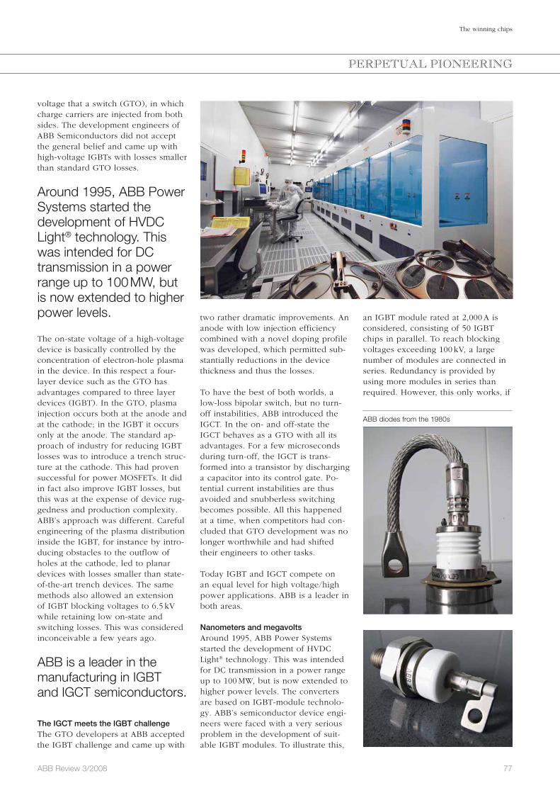
77ABB Review 3/2008
The winning chips
an IGBT module rated at 2,000 A is considered, consisting of 50 IGBT chips in parallel. To reach blocking voltages exceeding 100 kV, a large number of modules are connected in series. Redundancy is provided by using more modules in series than required. However, this only works, if
two rather dramatic improvements. An anode with low injection efficiency combined with a novel doping profile was developed, which permitted sub-stantially reductions in the device thickness and thus the losses.
To have the best of both worlds, a low-loss bipolar switch, but no turn-off instabilities, ABB introduced the IGCT. In the on- and off-state the IGCT behaves as a GTO with all its advantages. For a few microseconds during turn-off, the IGCT is trans-formed into a transistor by discharging a capacitor into its control gate. Po-tential current instabilities are thus avoided and snubberless switching becomes possible. All this happened at a time, when competitors had con-cluded that GTO development was no longer worthwhile and had shifted their engineers to other tasks.
Today IGBT and IGCT compete on an equal level for high voltage/high power applications. ABB is a leader in both areas.
Nanometers and megavoltsAround 1995, ABB Power Systems started the development of HVDC Light® technology. This was intended for DC transmission in a power range up to 100 MW, but is now extended to higher power levels. The converters are based on IGBT-module technolo-gy. ABB’s semiconductor device engi-neers were faced with a very serious problem in the development of suit-able IGBT modules. To illustrate this,
voltage that a switch (GTO), in which charge carriers are injected from both sides. The development engineers of ABB Semiconductors did not accept the general belief and came up with high-voltage IGBTs with losses smaller than standard GTO losses.
Around 1995, ABB Power Systems started the development of HVDC Light® technology. This was intended for DC transmission in a power range up to 100 MW, but is now extended to higher power levels.
The on-state voltage of a high-voltage device is basically controlled by the concentration of electron-hole plasma in the device. In this respect a four-layer device such as the GTO has advantages compared to three layer devices (IGBT). In the GTO, plasma injection occurs both at the anode and at the cathode; in the IGBT it occurs only at the anode. The standard ap-proach of industry for reducing IGBT losses was to introduce a trench struc-ture at the cathode. This had proven successful for power MOSFETs. It did in fact also improve IGBT losses, but this was at the expense of device rug-gedness and production complexity. ABB’s approach was different. Careful engineering of the plasma distribution inside the IGBT, for instance by intro-ducing obstacles to the outflow of holes at the cathode, led to planar devices with losses smaller than state-of-the-art trench devices. The same methods also allowed an extension of IGBT blocking voltages to 6.5 kV while retaining low on-state and switching losses. This was considered inconceivable a few years ago.
ABB is a leader in the manufacturing in IGBT and IGCT semiconductors.
The IGCT meets the IGBT challengeThe GTO developers at ABB accepted the IGBT challenge and came up with
PERPETUAL PIONEERING
ABB diodes from the 1980s
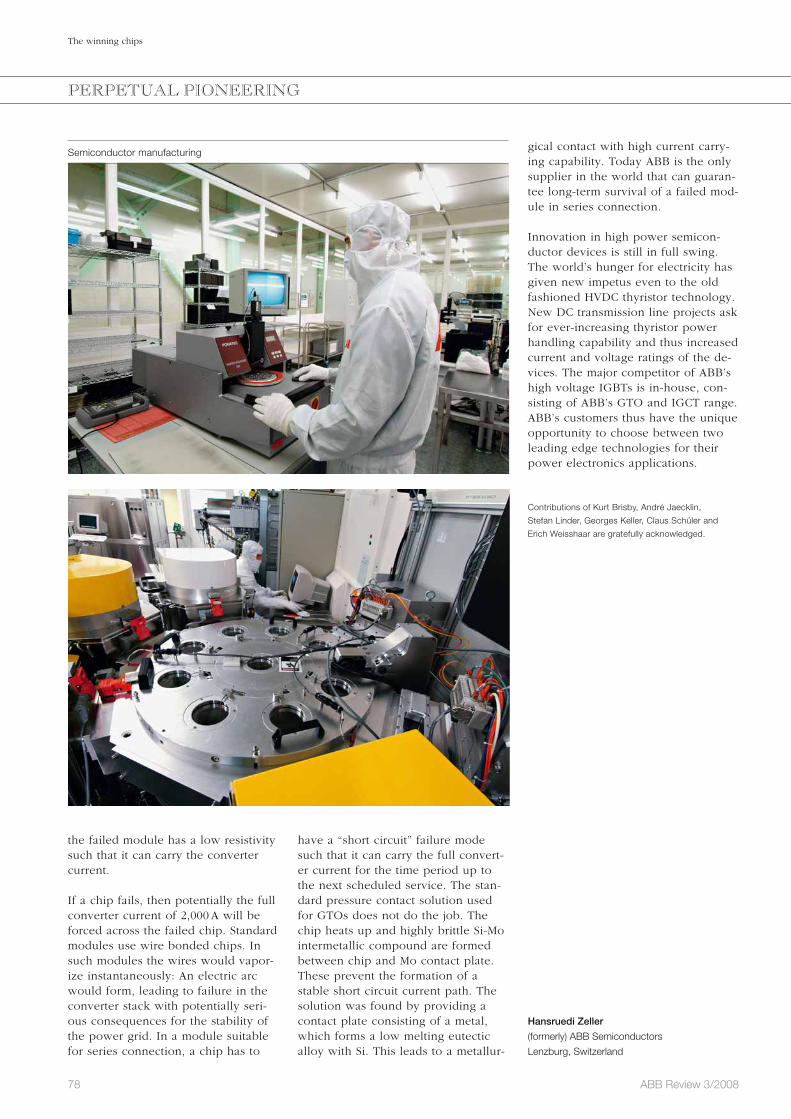
78 ABB Review 3/2008
The winning chips
gical contact with high current carry-ing capability. Today ABB is the only supplier in the world that can guaran-tee long-term survival of a failed mod-ule in series connection.
Innovation in high power semicon-ductor devices is still in full swing. The world’s hunger for electricity has given new impetus even to the old fashioned HVDC thyristor technology. New DC transmission line projects ask for ever-increasing thyristor power handling capability and thus increased current and voltage ratings of the de-vices. The major competitor of ABB’s high voltage IGBTs is in-house, con-sisting of ABB’s GTO and IGCT range. ABB’s customers thus have the unique opportunity to choose between two leading edge technologies for their power electronics applications.
Contributions of Kurt Brisby, André Jaecklin,
Stefan Linder, Georges Keller, Claus Schüler and
Erich Weiss haar are gratefully acknowledged.
Hansruedi Zeller
(formerly) ABB Semiconductors
Lenzburg, Switzerland
have a “short circuit” failure mode such that it can carry the full convert-er current for the time period up to the next scheduled service. The stan-dard pressure contact solution used for GTOs does not do the job. The chip heats up and highly brittle Si-Mo intermetallic compound are formed between chip and Mo contact plate. These prevent the formation of a stable short circuit current path. The solution was found by providing a contact plate consisting of a metal, which forms a low melting eutectic alloy with Si. This leads to a metallur-
the failed module has a low resistivity such that it can carry the converter current.
If a chip fails, then potentially the full converter current of 2,000 A will be forced across the failed chip. Standard modules use wire bonded chips. In such modules the wires would vapor-ize instantaneously: An electric arc would form, leading to failure in the converter stack with potentially seri-ous consequences for the stability of the power grid. In a module suitable for series connection, a chip has to
PERPETUAL PIONEERING
Semiconductor manufacturing

79ABB Review 3/2008
Preview 4/2008
Innovation highlights 2008
ABB has been reporting a growth in business and profitability for many quarters consecutively. The people who have contributed to this success include every one of the company’s employees, and also the suppliers who supported the company through excellent products and know-how. It also includes the customers through the full trust they showed in ABB’s capabilities.
The hallmark of the company’s suc-cess is the range of products and systems that fulfill the customer’s requirements so fittingly and make ABB the market leader in almost all the business in which it marks its presence. ABB continuously spends more than $1 billion every year to keep its products at the front end of technology and to develop them further through countless innova-tions.
The next issue of ABB Review focuses on some of these innovations. The breakthroughs that are presented were taken from all branches of the com-
pany’s manifold activities in the fields of power and automation technology.
ABB Review visits the world’s largest wind farms, which are equipped with ABB systems. It looks inside a 1 MV gas-insulated substation and takes a tour of HVDC Light® systems with a capability of more than 1 GW. This issue also reports on how the compa-ny solves security issues in large con-trol systems and presents the thrilling features of the company’s new robots.
A look back into the history of HVDC – a technology brought to the market by ABB 50 years ago – illustrates the stamina and effort needed to trans-form excellent ideas into winning products.
These are only part of the innovations presented in this issue. The ABB Re-view team hopes you will share their enthusiasm about the technical prog-ress the company made in 2008, and that your curiosity to learn more will be animated . . .
Editorial BoardPeter TerwieschChief Technology OfficerGroup R&D and Technology
Clarissa HallerHead of Corporate Communications
Ron PopperManager of Sustainability Affairs
Frank DugganRegion Manager, Middle East & Africa
Friedrich PinnekampChief Editor, ABB [email protected]
Andreas MoglestueDeputy Chief Editor, ABB [email protected]
PublisherABB Review is published by ABB Group R&D and Technology.
ABB Asea Brown Boveri Ltd.ABB Review/REVCH-8050 ZürichSwitzerland
ABB Review is published four times a year in English, French, German, Spanish, Chinese and Russian. ABB Review is free of charge to those with an interest in ABB’s technology and objectives. For a sub scription, please contact your nearest ABB representative or subscribe online at www.abb.com/abbreview
Partial reprints or reproductions are per-mitted subject to full acknowledgement. Complete reprints require the publisher’s written consent.
Publisher and copyright ©2008ABB Asea Brown Boveri Ltd. Zürich/Switzerland
PrinterVorarlberger Verlagsanstalt GmbHAT-6850 Dornbirn/Austria
LayoutDAVILLA Werbeagentur GmbHAT-6900 Bregenz/Austria
DisclaimerThe information contained herein reflects the views of the authors and is for informa-tional purposes only. Readers should not act upon the information contained herein without seeking professional advice. We make publications available with the under-standing that the authors are not rendering technical or other professional advice or opinions on specific facts or matters and assume no liability whatsoever in connec-tion with their use. The companies of the ABB Group do not make any warranty or guarantee, or promise, expressed or im-plied, concerning the content or accuracy of the views expressed herein.
ISSN: 1013-3119
www.abb.com/abbreview

Cities that consume 30% less energy?
Certainly.
As a leading producer of energy-effi cient solutions, ABB helps deliver major power savings, without compromising performance. Our lighting control systems can deliver power savings of up to 50 percent, and our building automation up to 60 percent. While everyone else is talking about energy prices, power shortages and climate change, ABB is doing something about it, right here, right now. www.abb.com/energyeffi ciency
a