Power Edger - ECHO USA · Power Edger Operator's Manual MODELS PE-230 Serial Number 05001001 -...
26
Power Edger Operator's Manual MODELS PE-230 Serial Number 05001001 - 05011200 WARNING DANGER X750003430 12/02 X7502098300 Read rules for safe operation and instructions carefully. ECHO provides an Operator's Manual and a Safety Manual. Both must be read and understood for proper and safe operation.
Transcript of Power Edger - ECHO USA · Power Edger Operator's Manual MODELS PE-230 Serial Number 05001001 -...

Power EdgerOperator's Manual
MODELS PE-230Serial Number 05001001 - 05011200
WARNING DANGER
X75000343012/02X7502098300
Read rules for safe operation and instructions carefully. ECHO provides anOperator's Manual and a Safety Manual. Both must be read and understood forproper and safe operation.
2INTRODUCTION
Welcome to the ECHO family. This ECHO product was designed and manufactured to provide long life and on-the-job-dependability. Read and understand this manual and the SAFETY MANUAL you found in the same package. You willfind both easy to use and full of helpful operations tips and SAFETY messages.
TABLE OF CONTENTS
Introduction ............................................................... 2- The Operator's Manual ....................................... 2- The Safety Manual ............................................. 2
Manual Safety Symbols and Important Information .. 3Safety ......................................................................... 3
- Decals .................................................................. 3- International Symbols ......................................... 4
Safety Instructions .................................................... 4- Personal Condition and Safety Equipment .......... 4- Extended Operation/Extreme Conditions ............. 5- Equipment ........................................................... 5- Safe Operation ..................................................... 6
Emission Control ........................................................ 6Description ................................................................ 7
- Contents .............................................................. 7Specifications ............................................................. 9Assembly ................................................................. 10
- Drive Shaft/Power Head .................................... 10- Throttle Linkage and Ignition Leads ................. 10- Front Handle .................................................... 11
Pre-Operation ........................................................... 11- Fuel ................................................................... 11
Operation ................................................................. 12
- Starting Cold Engine ......................................... 12- Starting Warm Engine ....................................... 13- Stopping Engine ................................................ 14- Operating Techniques ....................................... 14
Maintenance ............................................................ 16- Skill Levels ........................................................ 16- Maintenance Intervals ...................................... 16- Air Filter ............................................................ 17- Fuel Filter .......................................................... 17- Spark Plug ......................................................... 18- Cooling System ................................................. 18- Exhaust System ................................................. 19- Carburetor Adjustment ..................................... 20- Blade Replacement / Lubrication ....................... 21
Troubleshooting ...................................................... 24Storage ..................................................................... 25Servicing Information ............................................... 25
- Parts .................................................................. 25- Service ............................................................... 25- ECHO Consumer Product Support .................... 25- Warranty Card ................................................... 25- Additional or Replacement Manuals ................. 25- Supplement ....................................................... 26
Specifications, descriptions and illustrative material in thisliterature are as accurate as known at the time of publica-tion, but are subject to change without notice. Illustra-tions may include optional equipment and accessories,and may not include all standard equipment.
Copyright© 2002 By Echo, IncorporatedAll Rights Reserved.
THE OPERATOR'S MANUALRead and understand this manual before operation. Keep it in a safeplace for future reference. Contains specifications and information foroperation, starting, stopping, maintenance, storage and assemblyspecific to this product.
THE SAFETY MANUALRead and understand this manual before operation. Keep it in a safeplace for future reference. Explains possible hazards involved with theuse of Edgers and the measures you should take to make their use safer.
POWER EDGEROPERATOR'S MANUAL 3
SAFETY
DECALS
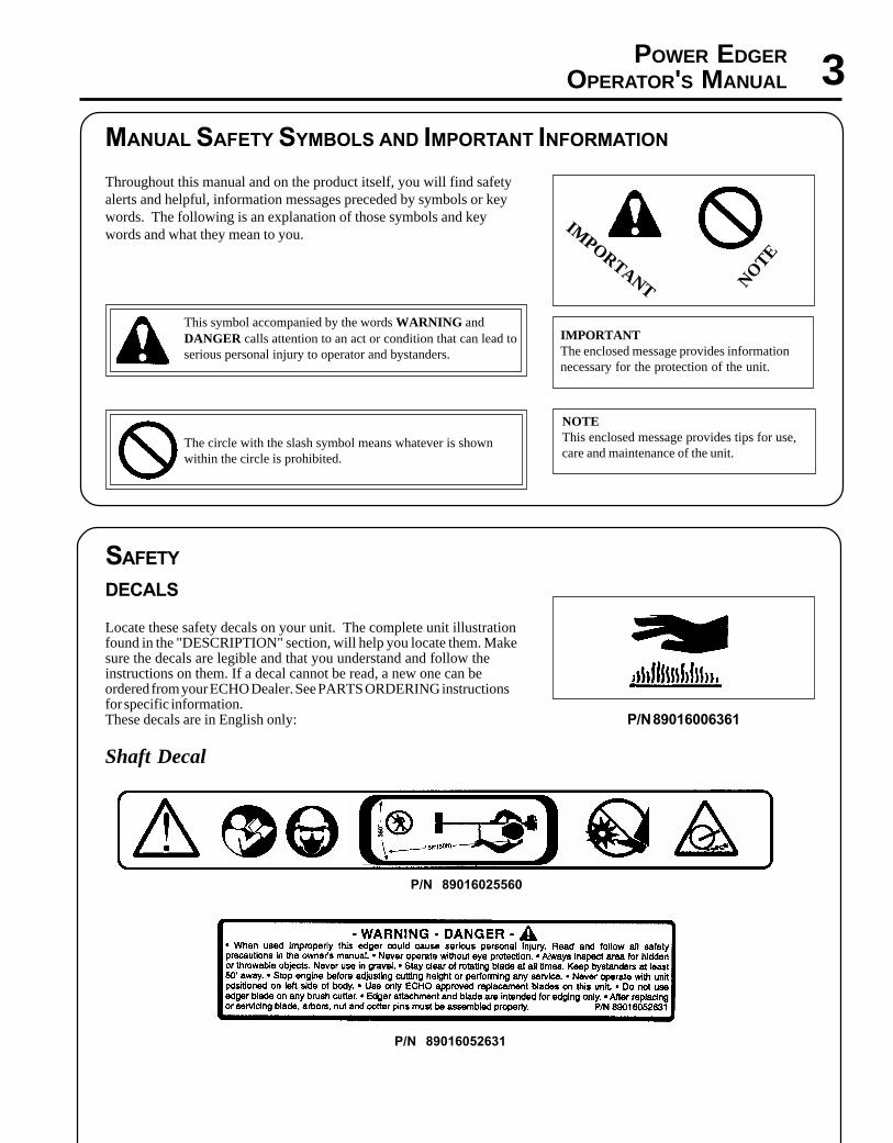
Locate these safety decals on your unit. The complete unit illustrationfound in the "DESCRIPTION" section, will help you locate them. Makesure the decals are legible and that you understand and follow theinstructions on them. If a decal cannot be read, a new one can beordered from your ECHO Dealer. See PARTS ORDERING instructionsfor specific information.These decals are in English only:
Shaft Decal
MANUAL SAFETY SYMBOLS AND IMPORTANT INFORMATION
Throughout this manual and on the product itself, you will find safetyalerts and helpful, information messages preceded by symbols or keywords. The following is an explanation of those symbols and keywords and what they mean to you.
This symbol accompanied by the words WARNING andDANGER calls attention to an act or condition that can lead toserious personal injury to operator and bystanders.
The circle with the slash symbol means whatever is shownwithin the circle is prohibited.
IMPORTANTThe enclosed message provides informationnecessary for the protection of the unit.
NOTEThis enclosed message provides tips for use,care and maintenance of the unit.
IMPORTANT NO
TE
P/N 89016025560
P/N 89016052631
P/N 89016006361
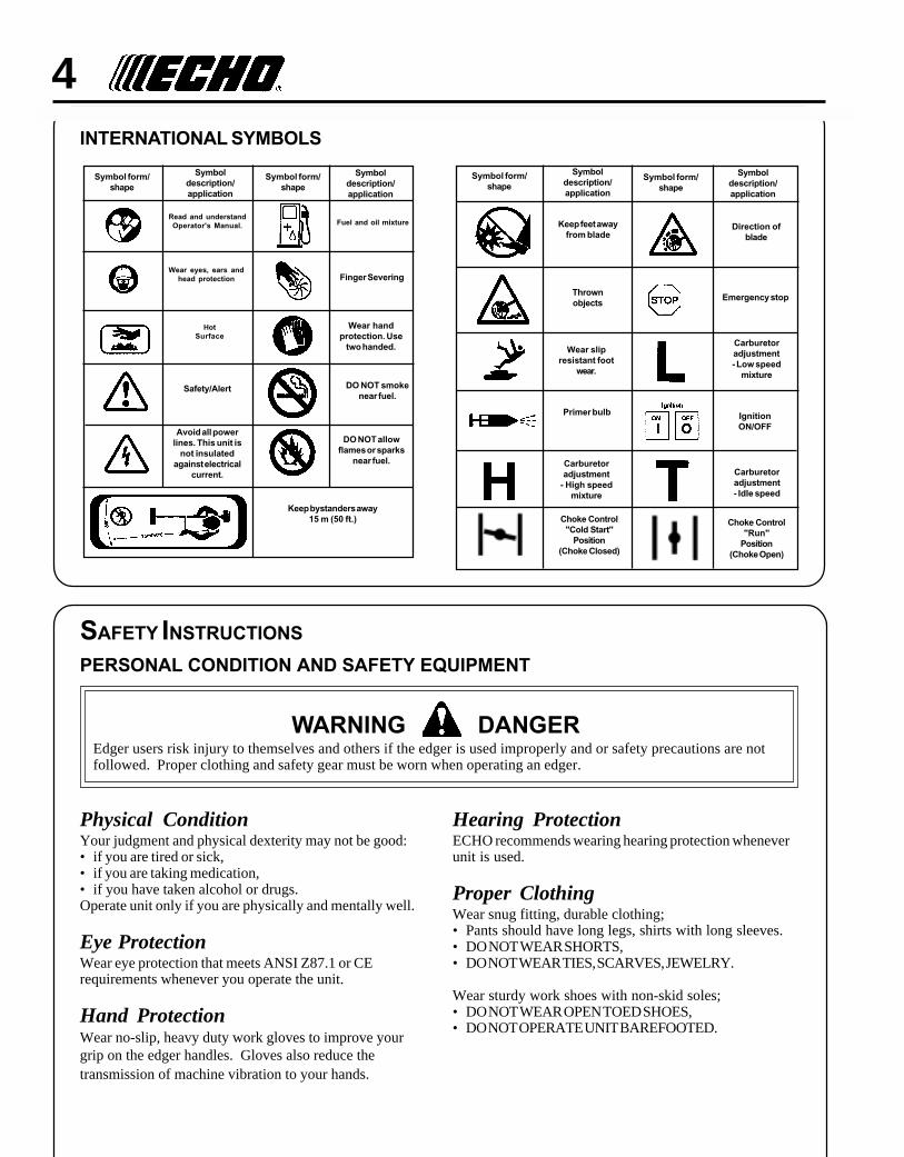
4INTERNATIONAL SYMBOLS
SAFETY INSTRUCTIONS
PERSONAL CONDITION AND SAFETY EQUIPMENT
WARNING DANGEREdger users risk injury to themselves and others if the edger is used improperly and or safety precautions are notfollowed. Proper clothing and safety gear must be worn when operating an edger.
Physical ConditionYour judgment and physical dexterity may not be good:• if you are tired or sick,• if you are taking medication,• if you have taken alcohol or drugs.Operate unit only if you are physically and mentally well.
Eye ProtectionWear eye protection that meets ANSI Z87.1 or CErequirements whenever you operate the unit.
Hand ProtectionWear no-slip, heavy duty work gloves to improve yourgrip on the edger handles. Gloves also reduce thetransmission of machine vibration to your hands.
Hearing ProtectionECHO recommends wearing hearing protection wheneverunit is used.
Proper ClothingWear snug fitting, durable clothing;• Pants should have long legs, shirts with long sleeves.• DO NOT WEAR SHORTS,• DO NOT WEAR TIES, SCARVES, JEWELRY.
Wear sturdy work shoes with non-skid soles;• DO NOT WEAR OPEN TOED SHOES,• DO NOT OPERATE UNIT BAREFOOTED.
HotSurface
Symboldescription/application
Symbol form/shape
Symboldescription/application
Symbol form/shape
Read and understandOperator's Manual.
Wear eyes, ears andhead protection
Fuel and oil mixture
Finger Severing
Safety/Alert
Avoid all powerlines. This unit is
not insulatedagainst electrical
current.
Wear handprotection. Use
two handed.
DO NOT smokenear fuel.
DO NOT allowflames or sparks
near fuel.
Keep bystanders away15 m (50 ft.)
Symboldescription/application
Symbol form/shape
Symboldescription/application
Symbol form/shape
Carburetoradjustment- Idle speed
Carburetoradjustment
- High speedmixture
Emergency stop
Carburetoradjustment- Low speed
mixture
Wear slipresistant foot
wear.
IgnitionON/OFF
Primer bulb
Keep feet awayfrom blade
Thrownobjects
Direction ofblade
Choke Control"Cold Start"
Position(Choke Closed)
Choke Control"Run"
Position(Choke Open)

POWER EDGEROPERATOR'S MANUAL 5
EXTENDED OPERATION/EXTREME CONDITIONS
Vibration and ColdIt is believed that a condition called Raynaud’s Phenomenon, whichaffects the fingers of certain individuals, may be brought about byexposure to vibration and cold. Exposure to vibration and cold maycause tingling and burning sensations, followed by loss of color andnumbness in the fingers. The following precautions are stronglyrecommended, because the minimum exposure which might trigger theailment is unknown.
• Keep your body warm, especially the head, neck, feet, ankles, hands,and wrists.
• Maintain good blood circulation by performing vigorous armexercisesduring frequent work breaks, and also by not smoking.
• Limit the hours of operation. Try to fill each day with jobs whereoperating the edger or other hand-held power equipment is notrequired.
• If you experience discomfort, redness and swelling of the fingers,followed by whitening and loss of feeling, consult your physicianbefore further exposing yourself to cold and vibration.
Repetitive Stress InjuriesIt is believed that overusing the muscles and tendons of the fingers,hands, arms, and shoulders may cause soreness, swelling, numbness,weakness, and extreme pain in those areas. Certain repetitive handactivities may put you at a high risk for developing a Repetitive StressInjury (RSI). An extreme RSI condition is Carpal Tunnel Syndrome(CTS), which could occur when your wrist swells and squeezes a vitalnerve that runs through the area. Some believe that prolonged exposureto vibration may contribute to CTS. CTS can cause severe pain formonths or even years.
To reduce the risk of RSI/CTS, do thefollowing:
• Avoid using your wrist in a bent, ex-tended, or twisted position. Instead, try tomaintain a straight wrist position. Also,when grasping, use your whole hand, notjust the thumb and index finger.
• Take periodic breaks to minimize repetitionand rest your hands.
• Reduce the speed and force with whichyou do the repetitive movement.
• Do exercises to strengthen the hand andarm muscles.
• Immediately stop using all power equip-ment and consult a doctor if you feeltingling, numbness, or pain in the fingers,hands, wrists, or arms. The sooner RSI/CTS is diagnosed, the more likely perma-nent nerve and muscle damage can beprevented.
EQUIPMENT
• Check unit for loose/missing nuts, bolts and screws. Tighten and/orreplace as needed.
• Inspect fuel lines, tank, and area around carburetor for fuel leaks. DONOT operate unit if leaks are found.
• Inspect shield for damage, and that shield is securely in place.Replace if shield is damaged or missing.
• Check that the cutting attachment is firmly attached and in safeoperating condition.
• Check that front handle is adjusted for safe, comfortable operation.See Assembly for proper adjustment.
• Keep exhaust area clear of flammable debris. Avoid contact duringand immediately after operation.
WARNING DANGERUse only ECHO approved attachments. Serious injury may result from the use of a non approved attachmentcombination. ECHO, INC. will not be responsible for the failure of cutting devices, attachments or accessories whichhave not been tested and approved by ECHO. Read and comply with all safety instructions listed in this manual andsafety manual.
6
SAFE OPERATION
WARNING DANGERDo not operate this product indoors or in inadequately ventilatedareas. Engine exhaust contains poisonous emissions and can causeserious injury or death.
Provide Operating And Safety Instructions To All Operators• Provide all operators of this equipment with the Operator's Manual
and Safety Manual for instructions on safe operation.
Keep A Firm Grip• Hold the front and center or rear and center handles with both hands,
with thumbs and fingers tightly encircling the handles
Keep A Solid Stance• Maintain footing and balance at all times. Do not stand on slippery,
uneven or unstable surfaces. Do not work in odd positions or onladders. Do not over reach.
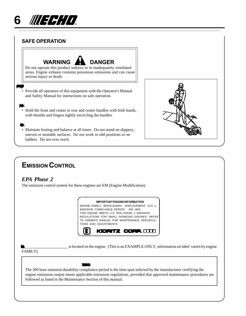
IMPORTANT ENGINE INFORMATIONENGINE FAMILY: 3EHXS.0234EA DISPLACEMENT: 22.8 CC
EMISSION COMPLIANCE PERIOD : 300 HRS.THIS ENGINE MEETS U.S. EPA PHASE 2 EMISSIONREGULATIONS FOR SMALL NONROAD ENGINES. REFERTO OWNER'S MANUAL FOR MAINTENANCE SPECIFICA-TIONS AND ADJUSTMENTS.
EMISSION CONTROL
EPA Phase 2The emission control system for these engines are EM (Engine Modification).
PRODUCT EMISSION DURABILITYThe 300 hour emission durability compliance period is the time span selected by the manufacturer certifying theengine emissions output meets applicable emissions regulations, provided that approved maintenance procedures arefollowed as listed in the Maintenance Section of this manual.
An Emission Control Label is located on the engine. (This is an EXAMPLE ONLY, information on label varies by engineFAMILY).
POWER EDGEROPERATOR'S MANUAL 7
DESCRIPTION
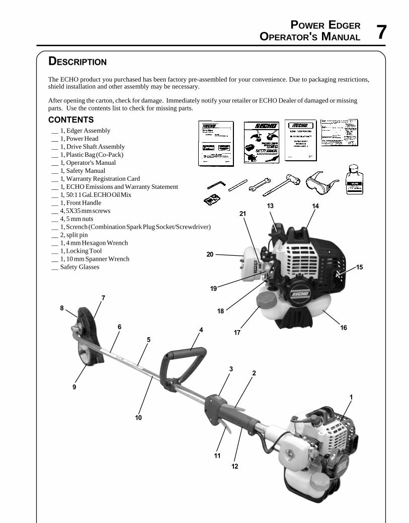
The ECHO product you purchased has been factory pre-assembled for your convenience. Due to packaging restrictions,shield installation and other assembly may be necessary.
After opening the carton, check for damage. Immediately notify your retailer or ECHO Dealer of damaged or missingparts. Use the contents list to check for missing parts.
CONTENTS__ 1, Edger Assembly__ 1, Power Head__ 1, Drive Shaft Assembly__ 1, Plastic Bag (Co-Pack)__ 1, Operator's Manual__ 1, Safety Manual__ 1, Warranty Registration Card__ 1, ECHO Emissions and Warranty Statement__ 1, 50:1 1 Gal. ECHO Oil Mix__ 1, Front Handle__ 4, 5X35 mm screws__ 4, 5 mm nuts__ 1, Scrench (Combination Spark Plug Socket/Screwdriver)__ 2, split pin__ 1, 4 mm Hexagon Wrench__ 1, Locking Tool__ 1, 10 mm Spanner Wrench__ Safety Glasses 15
1617
18
19
14
4
1
5
6
7
8
9
10
11
2
12
3
13
20
21
8
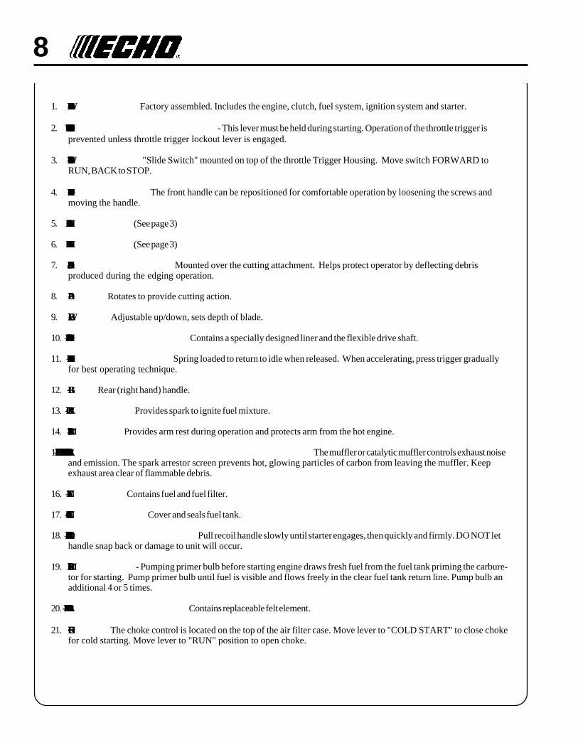
1. POWER HEAD - Factory assembled. Includes the engine, clutch, fuel system, ignition system and starter.
2. THROTTLE TRIGGER LOCKOUT - This lever must be held during starting. Operation of the throttle trigger isprevented unless throttle trigger lockout lever is engaged.
3. STOP SWITCH - "Slide Switch" mounted on top of the throttle Trigger Housing. Move switch FORWARD toRUN, BACK to STOP.
4. FRONT HANDLE - The front handle can be repositioned for comfortable operation by loosening the screws andmoving the handle.
5. SHAFT DECAL (See page 3)
6. SHAFT DECAL (See page 3)
7. DEBRIS SHIELD/FLAP - Mounted over the cutting attachment. Helps protect operator by deflecting debrisproduced during the edging operation.
8. BLADE - Rotates to provide cutting action.
9. WHEEL - Adjustable up/down, sets depth of blade.
10. DRIVE SHAFT ASSEMBLY - Contains a specially designed liner and the flexible drive shaft.
11. THROTTLE TRIGGER - Spring loaded to return to idle when released. When accelerating, press trigger graduallyfor best operating technique.
12. GRIP - Rear (right hand) handle.
13. SPARK PLUG - Provides spark to ignite fuel mixture.
14. ARM REST - Provides arm rest during operation and protects arm from the hot engine.
15. SPARK ARRESTOR - CATALYTIC MUFFLER / MUFFLER - The muffler or catalytic muffler controls exhaust noiseand emission. The spark arrestor screen prevents hot, glowing particles of carbon from leaving the muffler. Keepexhaust area clear of flammable debris.
16. FUEL TANK - Contains fuel and fuel filter.
17. FUEL TANK CAP - Cover and seals fuel tank.
18. RECOIL STARTER HANDLE - Pull recoil handle slowly until starter engages, then quickly and firmly. DO NOT lethandle snap back or damage to unit will occur.
19. PRIMER BULB - Pumping primer bulb before starting engine draws fresh fuel from the fuel tank priming the carbure-tor for starting. Pump primer bulb until fuel is visible and flows freely in the clear fuel tank return line. Pump bulb anadditional 4 or 5 times.
20. AIR CLEANER ASSEMBLY - Contains replaceable felt element.
21. CHOKE - The choke control is located on the top of the air filter case. Move lever to "COLD START" to close chokefor cold starting. Move lever to "RUN" position to open choke.

POWER EDGEROPERATOR'S MANUAL 9
SPECIFICATIONS
MODEL ----------------------------------------------------- PE-230
Length ------------------------------------------------------- 1755 mm (69.1 in.)
Width -------------------------------------------------------- 315 mm (12.4 in.)
Height ------------------------------------------------------- 285 mm (11.2 in.)
Weight (dry w/cutter head) ------------------------------- 6.1 kg (13.4 lb.)
Engine Type ------------------------------------------------ Air cooled, two-stroke, single cylinder gasoline engine
Bore ---------------------------------------------------------- 32.2 mm (1.27 in.)
Stroke -------------------------------------------------------- 28.0 mm (1.10 in.)
Displacement ----------------------------------------------- 22.8 cc (1.39 cu. in.)
Exhaust ------------------------------------------------------ Spark Arrestor Muffler
Carburetor diaphragm w/purge --------------------------- Zama model RB
Ignition System -------------------------------------------- CDI (capacitor discharge ignition)
Spark Plug -------------------------------------------------- NGK BPM-8Y 0.65mm (0.026 in.)
Fuel ---------------------------------------------------------- Mixed (Gasoline and Two-stroke Oil)
Fuel/Oil Ratio ----------------------------------------------- 50:1 ECHO High Performance, two-stroke air cooled engine oil
Gasoline ----------------------------------------------------- 89 Octane unleaded. DO NOT use fuel containing methyl alcohol
more than 10% ethyl alcohol or 15% MTBE.
Oil ------------------------------------------------------------ 50:1 ECHO High Performance, two-stroke air cooled engine oil
Fuel Tank Capacity ---------------------------------------- 0.58 lit. (19.6 US fl. oz.)
Recoil Starter System -------------------------------------- Automatic Recoil Starter
Clutch ------------------------------------------------------- Centrifugal Type
Drive Shaft -------------------------------------------------- 6.35 mm (1/4 in.) flexible shaft
Rotation Direction ----------------------------------------- Clockwise viewed from right side
Edger Head ------------------------------------------------- Metal blade
Blade Length ----------------------------------------------- 203.2 mm (8.0 in.)
Blade Width ------------------------------------------------ 50.8 mm (2 in.)
Blade Thickness ------------------------------------------- 2.3 mm (0.090 in.)
Handle ------------------------------------------------------- Left Cushioned - D-loop, Right - Grip
Vibration Reduction --------------------------------------- Rubber Cushion
Idle Speed (RPM) ------------------------------------------ 2400 - 3200
Wide Open Throttle Speed (RPM) ---------------------- 10,000 - 11,000

10ASSEMBLY
DRIVE SHAFT/POWER HEAD
Tools Required: 4 mm Hex Wrench
Parts Required: Power Head, Drive Shaft Assembly
1. Loosen, the bolt (A) at engine drive shaft clamp.
2. Carefully fit drive shaft assembly to engine making sure thatinner drive shaft engages into clutch mount.
NOTELower gear housing and head assembly must be in line with theengine.
3. Turn drive shaft housing so that center line of housing is midwaybetween the two arrows on shaft.
4. Tighten bolt (A).
THROTTLE LINKAGE AND IGNITION LEADS
1. Connect ignition stop leads (A) and (B).
2. Place throttle linkage (C) through adjustment fixture (D) and installwire end into large carburetor throttle swivel hole (E). Check throttlefor freedom of movement and that wide open throttle / low idleextremes are adjusted properly. The throttle linkage must beadjusted by moving the adjustment fixture (D). Consult with yourEcho Dealer for correct adjustment procedure.
3. Bundle and secure ignition leads against engine housing with clip(F).
A
A
A
B
C
DE
F
POWER EDGEROPERATOR'S MANUAL 11
FRONT HANDLE
Tools Required: Cross-Head Screwdriver
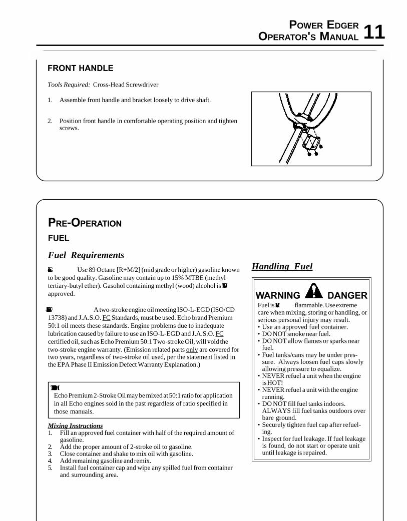
1. Assemble front handle and bracket loosely to drive shaft.
2. Position front handle in comfortable operating position and tightenscrews.
PRE-OPERATION
FUEL
Fuel Requirements
Gasoline - Use 89 Octane [R+M/2] (mid grade or higher) gasoline knownto be good quality. Gasoline may contain up to 15% MTBE (methyltertiary-butyl ether). Gasohol containing methyl (wood) alcohol is NOTapproved.
Two Stroke Oil - A two-stroke engine oil meeting ISO-L-EGD (ISO/CD13738) and J.A.S.O. FC Standards, must be used. Echo brand Premium50:1 oil meets these standards. Engine problems due to inadequatelubrication caused by failure to use an ISO-L-EGD and J.A.S.O. FCcertified oil, such as Echo Premium 50:1 Two-stroke Oil, will void thetwo-stroke engine warranty. (Emission related parts only are covered fortwo years, regardless of two-stroke oil used, per the statement listed inthe EPA Phase II Emission Defect Warranty Explanation.)
IMPORTANTEcho Premium 2-Stroke Oil may be mixed at 50:1 ratio for applicationin all Echo engines sold in the past regardless of ratio specified inthose manuals.
Mixing Instructions1. Fill an approved fuel container with half of the required amount of
gasoline.2. Add the proper amount of 2-stroke oil to gasoline.3. Close container and shake to mix oil with gasoline.4. Add remaining gasoline and remix.5. Install fuel container cap and wipe any spilled fuel from container
and surrounding area.
Handling Fuel
WARNING DANGERFuel is VERY flammable. Use extremecare when mixing, storing or handling, orserious personal injury may result.• Use an approved fuel container.• DO NOT smoke near fuel.• DO NOT allow flames or sparks near
fuel.• Fuel tanks/cans may be under pres-
sure. Always loosen fuel caps slowlyallowing pressure to equalize.
• NEVER refuel a unit when the engineis HOT!
• NEVER refuel a unit with the enginerunning.
• DO NOT fill fuel tanks indoors.ALWAYS fill fuel tanks outdoors overbare ground.
• Securely tighten fuel cap after refuel-ing.
• Inspect for fuel leakage. If fuel leakageis found, do not start or operate unituntil leakage is repaired.

12
IMPORTANTSpilled fuel is a leading cause of hydrocarbon emissions. Somestates may require the use of automatic fuel shut-off containers toreduce fuel spillage. Contact your ECHO dealer for orderinginformation.
After refueling;• Wipe any spilled fuel from the unit.• Move at least 3 m (10 ft.) from refueling location before starting the
engine.
After use;• DO NOT store a unit with fuel in its tank. Leaks can occur. Return
unused fuel to an approved fuel storage container.
Storage -Fuel storage laws vary by locality. Contactyour local government for the laws affectingyour area. As a precaution, store fuel in anapproved, air tight container. Store in a wellventilated, unoccupied building, away fromsparks and flames. Do not store fuel longerthan 30 days.
IMPORTANTStored fuel ages. Do not mix more fuelthan you expect to use in thirty (30)days, ninety (90) days when a fuelstabilizer is added.
IMPORTANTStored two-stroke fuel may separate.ALWAYS shake fuel container thor-oughly before each use.
OPERATION
STARTING COLD ENGINE
WARNING DANGERThe cutting attachment should not rotate at idle. If attachmentrotates, readjust carburetor according to "Carburetor Adjustment"instructions in this manual or see your ECHO Dealer, otherwiseserious personal injury may result.
1. Stop SwitchMove stop switch button (A) forward away from the STOPposition.
2. Choke
Move choke lever (B) to Cold Start ( ) Position.
3. PrimerPump primer bulb (C) until fuel is visible in the "Clear" fuel returnline. Pump bulb an additional 4 or 5 times. B
C
A
POWER EDGEROPERATOR'S MANUAL 13
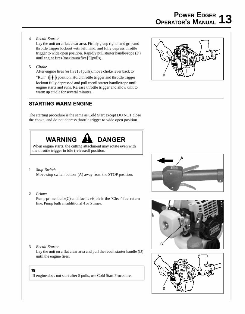
4. Recoil StarterLay the unit on a flat, clear area. Firmly grasp right hand grip andthrottle trigger lockout with left hand, and fully depress throttletrigger to wide open position. Rapidly pull starter handle/rope (D)until engine fires (maximum five [5] pulls).
5. ChokeAfter engine fires (or five [5] pulls), move choke lever back to
“Run” ( ) position. Hold throttle trigger and throttle triggerlockout fully depressed and pull recoil starter handle/rope untilengine starts and runs. Release throttle trigger and allow unit towarm up at idle for several minutes.
STARTING WARM ENGINE
The starting procedure is the same as Cold Start except DO NOT closethe choke, and do not depress throttle trigger to wide open position.
WARNING DANGERWhen engine starts, the cutting attachment may rotate even withthe throttle trigger in idle (released) position.
1. Stop SwitchMove stop switch button (A) away from the STOP position.
2. PrimerPump primer bulb (C) until fuel is visible in the "Clear" fuel returnline. Pump bulb an additional 4 or 5 times.
3. Recoil StarterLay the unit on a flat clear area and pull the recoil starter handle (D)until the engine fires.
NOTEIf engine does not start after 5 pulls, use Cold Start Procedure.
D
C
D
A

14STOPPING ENGINE
1. ThrottleRelease throttle, and allow engine to return to idle before shuttingoff engine.
2. Stop SwitchMove stop switch button (A) backward to STOP position.
WARNING DANGERIf engine does not stop when stop switch is moved to STOPposition, close choke - COLD START position - to stall engine.Have your ECHO dealer repair stop switch before using edgeragain.
OPERATING TECHNIQUES
1. Before edging, water the area to soften the ground to make edgingeasier.
2 Before edging, check the area and remove all obstacles andobjects that could be thrown.
3. Plan to edge regularly to make it easier to keep a neat edge and toavoid having to make more than one pass.
NOTEBlade depth may have to be adjusted due to differences in heightbetween the hard surface and the top of the grass.
WARNING DANGERNever adjust blade height with engine running, otherwise seriouspersonal injury may result.
4. Adjust the blade's depth of cut to produce a fine cut betweensidewalk and grass using a minimum blade depth, usually withabout 13 mm (1/2 in.) of the blade into the ground.
5. Before edging, plan your direction of travel so that the unit willalways be positioned on your right side and so that you walk on ahard surface whenever possible.
6. Hold edger as shown.
A
INCREASEDEPTH
WHEELADJUSTMENT
KNOB
DECREASEDEPTH
1/2 in.
POWER EDGEROPERATOR'S MANUAL 15
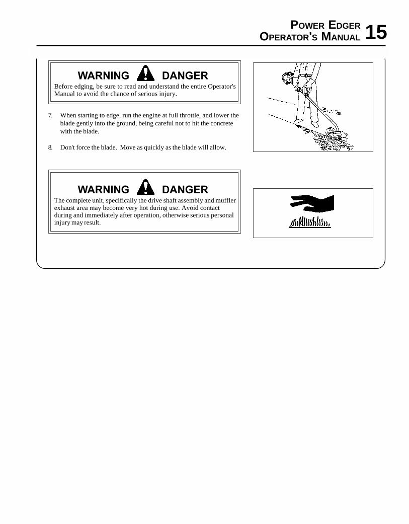
WARNING DANGERBefore edging, be sure to read and understand the entire Operator'sManual to avoid the chance of serious injury.
7. When starting to edge, run the engine at full throttle, and lower theblade gently into the ground, being careful not to hit the concretewith the blade.
8. Don't force the blade. Move as quickly as the blade will allow.
WARNING DANGERThe complete unit, specifically the drive shaft assembly and mufflerexhaust area may become very hot during use. Avoid contactduring and immediately after operation, otherwise serious personalinjury may result.

16MAINTENANCEYour ECHO edger is designed to provide many hours of trouble free service. Regular scheduled maintenance will helpyour edger achieve that goal. If you are unsure or are not equipped with the necessary tools, you may want to take yourunit to an ECHO Service Dealer for maintenance. To help you decide whether you want to DO-IT-YOURSELF or have theECHO Dealer do it, each maintenance task has been graded. If the task is not listed, see your ECHO Dealer for repairs.
SKILL LEVEL
Level 1 = Easy to do. Most required tools come with unit.Level 2 = Moderate difficulty. Some specialized tools may be required.Level 3 = Experience required. Specialized tools are required. ECHO recommends
that the unit be returned to your ECHO dealer for service.
ECHO offers REPOWERTM Maintenance Kits and Parts to make your maintenance job easier. Just below each taskheading are listed the various part numbers required for that task. See your ECHO dealer for these parts.
/TNENOPMOCMETSYS
ECNANETNIAMERUDECORP
D'QERLLIKSLEVEL
ROYLIADEROFEB
ESU
YREVELEUFER
3SHTNOM
09ROSRUOH
6SHTNOM
072ROSRUOH
YLRAEY006
SRUOH
serudecorPecnanetniaMrelaeDohcEdednemmoceR
troPtsuahxErednilyC nobraceD/naelC/tcepsnI 3 C/I
serudecorPecnanetniaMflesruoY-tI-oD
retliFriA ecalpeR/naelC/tcepsnI 1 C/I *R
ekohC naelC/tcepsnI 2 C/I
retliFleuF ecalpeR/tcepsnI 1 I *R
skael,metsySleuF ecalpeR/tcepsnI 1 I *R/I
metsySgnilooC naelC/tcepsnI 2 C/I
rotserrAkrapSrelffuM ecalpeR/tcepsnI 2 C/I *R/I
tfahSevirD esaerG 2 )1(I
gnisuoHraeG esaerG 2 )2(I
epoRretratSlioceR naelC/tcepsnI 1 *C/I *R/I
gulPkrapS naelC/tcepsnI 2 C/I *R
tnemecalpeRedalB ecalpeR/tcepsnI 1 I I *R/I
stloB/stuN/swercS ecalpeR/nethgiT/tcepsnI 1 *R/I
SEDOCRETTELERUDECORPECNANETNIAM NAELC=C,ECALPER=R,TCEPSNI=I:-ETONTNATROPMI deriuqerfoycneuqerfehtenimretedlliwecneirepxeruoydnaesulautcA.mumixameranwohsslavretniemiT
.ecnanetniam:SETONERUDECORPECNANETNIAM
)1( OHCEylppA ® EBUL MT .esufosruoh05yreve)2( OHCEylppA ® EBUL MT .esufosruoh52-51yreve
* ..noitcepsnignirudraewroegamadfognidnifehtnodesaberaecalperotsnoitadnemmocerllA
MAINTENANCE INTERVALS

POWER EDGEROPERATOR'S MANUAL 17
AIR FILTER
Level 1.
Tools required: Cleaning brush, 25 or 50 mm (1 or 2 in.) medium bristlepaint brush.
Parts required: 90008 REPOWERTM Air & Fuel Filter Kit.
1. Close choke (Cold Start Position). This prevents dirt fromentering the carburetor throat when the air filter is removed.Brush accumulated dirt from the air cleaner area.
2. Remove the air cleaner cover. Clean and inspect the element fordamage. If element is fuel soaked and very dirty, replace.
3. If element can be cleaned and reused, be certain it:-still fits the cavity in the air cleaner cover.-is installed with the original side out.
FUEL FILTER
Level 1.
Tools required: Fuel line hook, 200-250 mm (8-10 in.) length of wirewith one end bent into a hook. Clean rag, funnel, andan approved fuel container.
Parts required: 90008 REPOWERTM Air & Fuel Filter Kit.
WARNING DANGERFuel is VERY flammable. Use extreme care when mixing, storing orhandling.
1. Use a clean rag to remove loose dirt from around fuel cap andempty fuel tank.
2. Use the “fuel line hook” to pull the fuel line and filter from thetank.
3. Remove the filter from the line and install the new filter.
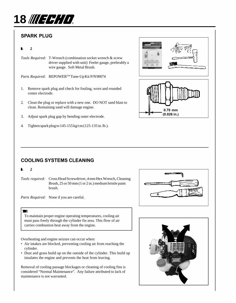
18SPARK PLUG
Level 2.
Tools Required: T-Wrench (combination socket wrench & screwdriver supplied with unit) Feeler gauge, preferably awire gauge. Soft Metal Brush.
Parts Required: REPOWERTM Tune-Up Kit P/N 90074
1. Remove spark plug and check for fouling, worn and roundedcenter electrode.
2. Clean the plug or replace with a new one. DO NOT sand blast toclean. Remaining sand will damage engine.
3. Adjust spark plug gap by bending outer electrode.
4. Tighten spark plug to 145-155 kg/cm (125-135 in. lb.).
COOLING SYSTEMS CLEANING
Level 2.
Tools required: Cross Head Screwdriver, 4 mm Hex Wrench, CleaningBrush, 25 or 50 mm (1 or 2 in.) medium bristle paintbrush.
Parts Required: None if you are careful.
IMPORTANTTo maintain proper engine operating temperatures, cooling airmust pass freely through the cylinder fin area. This flow of aircarries combustion heat away from the engine.
Overheating and engine seizure can occur when:• Air intakes are blocked, preventing cooling air from reaching the
cylinder.• Dust and grass build up on the outside of the cylinder. This build up
insulates the engine and prevents the heat from leaving.
Removal of cooling passage blockages or cleaning of cooling fins isconsidered “Normal Maintenance”. Any failure attributed to lack ofmaintenance is not warranted.
0.70 mm(0.026 in.)
POWER EDGEROPERATOR'S MANUAL 19
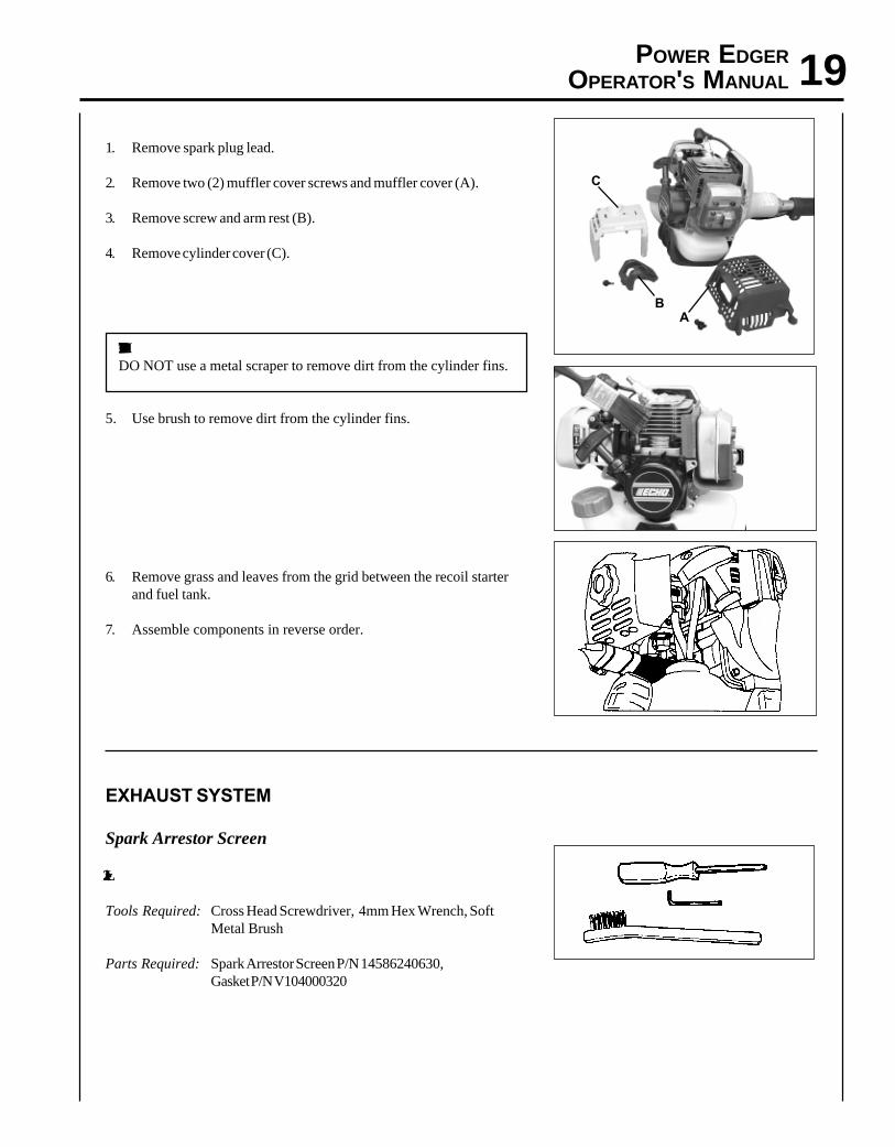
1. Remove spark plug lead.
2. Remove two (2) muffler cover screws and muffler cover (A).
3. Remove screw and arm rest (B).
4. Remove cylinder cover (C).
IMPORTANTDO NOT use a metal scraper to remove dirt from the cylinder fins.
5. Use brush to remove dirt from the cylinder fins.
6. Remove grass and leaves from the grid between the recoil starterand fuel tank.
7. Assemble components in reverse order.
EXHAUST SYSTEM
Spark Arrestor Screen
Level 2.
Tools Required: Cross Head Screwdriver, 4mm Hex Wrench, SoftMetal Brush
Parts Required: Spark Arrestor Screen P/N 14586240630,Gasket P/N V104000320
AB
C
20
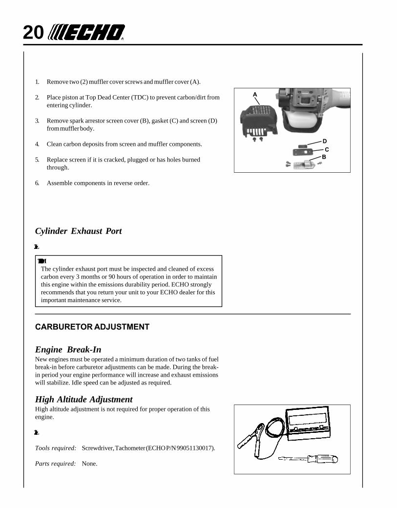
1. Remove two (2) muffler cover screws and muffler cover (A).
2. Place piston at Top Dead Center (TDC) to prevent carbon/dirt fromentering cylinder.
3. Remove spark arrestor screen cover (B), gasket (C) and screen (D)from muffler body.
4. Clean carbon deposits from screen and muffler components.
5. Replace screen if it is cracked, plugged or has holes burnedthrough.
6. Assemble components in reverse order.
Cylinder Exhaust Port
Level 3.
IMPORTANTThe cylinder exhaust port must be inspected and cleaned of excesscarbon every 3 months or 90 hours of operation in order to maintainthis engine within the emissions durability period. ECHO stronglyrecommends that you return your unit to your ECHO dealer for thisimportant maintenance service.
CARBURETOR ADJUSTMENT
Engine Break-InNew engines must be operated a minimum duration of two tanks of fuelbreak-in before carburetor adjustments can be made. During the break-in period your engine performance will increase and exhaust emissionswill stabilize. Idle speed can be adjusted as required.
High Altitude AdjustmentHigh altitude adjustment is not required for proper operation of thisengine.
Level 2.
Tools required: Screwdriver, Tachometer (ECHO P/N 99051130017).
Parts required: None.
BC
D
A
POWER EDGEROPERATOR'S MANUAL 21
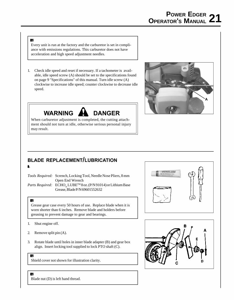
NOTEEvery unit is run at the factory and the carburetor is set in compli-ance with emissions regulations. This carburetor does not haveacceleration and high speed adjustment needles.
1. Check idle speed and reset if necessary. If a tachometer is avail-able, idle speed screw (A) should be set to the specifications foundon page 9 "Specifications" of this manual. Turn idle screw (A)clockwise to increase idle speed; counter clockwise to decrease idlespeed.
WARNING DANGERWhen carburetor adjustment is completed, the cutting attach-ment should not turn at idle, otherwise serious personal injurymay result.
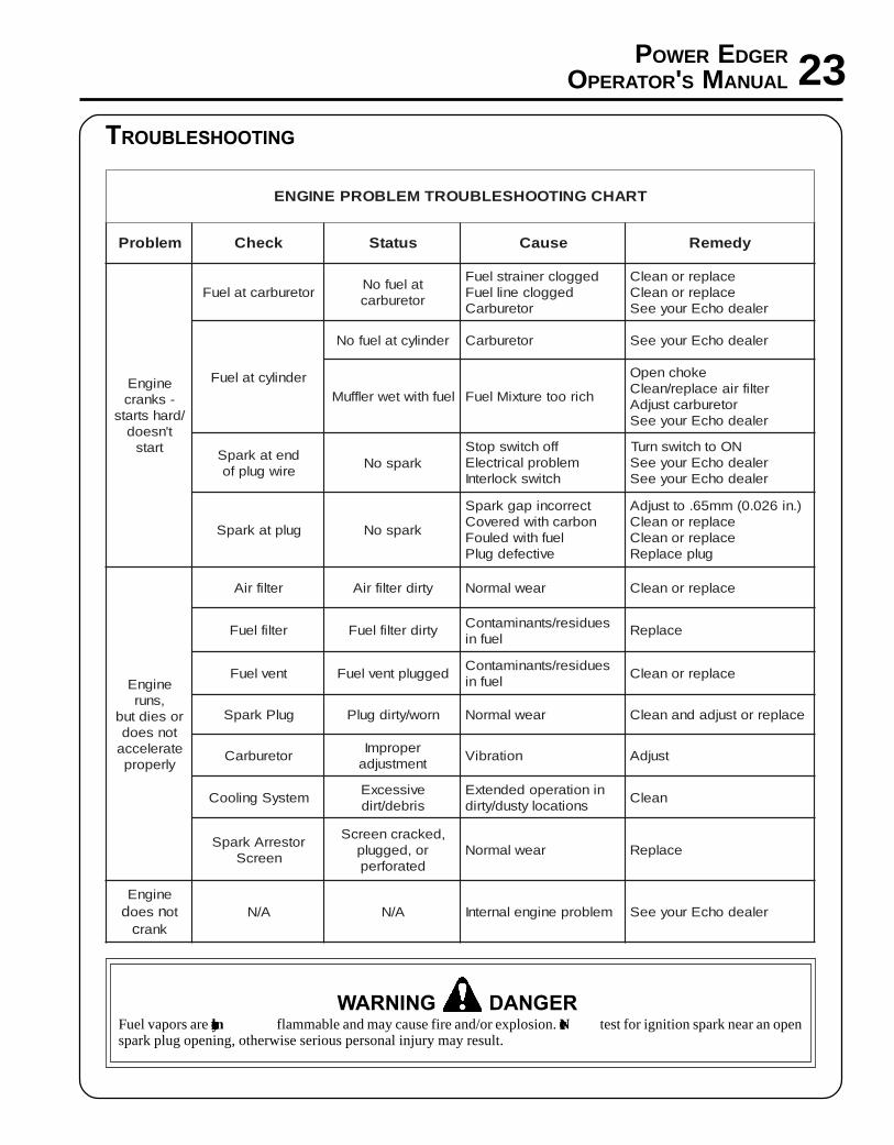
BLADE REPLACEMENT/LUBRICATIONLevel 1.
Tools Required: Scrench, Locking Tool, Needle Nose Pliers, 8 mmOpen End Wrench
Parts Required: ECHO® LUBETM 8 oz. (P/N 91014) or Lithium Base
Grease, Blade P/N 69601552632
NOTEGrease gear case every 50 hours of use. Replace blade when it isworn shorter than 6 inches. Remove blade and holders beforegreasing to prevent damage to gear and bearings.
1. Shut engine off.
2. Remove split pin (A).
3. Rotate blade until holes in inner blade adapter (B) and gear boxalign. Insert locking tool supplied to lock PTO shaft (C).
NOTEShield cover not shown for illustration clarity.
NOTEBlade nut (D) is left hand thread.
A

22
4. Remove blade nut (D) in a clockwise direction using box wrenchsupplied. Remove outer blade adapter (E), blade (F) and inner bladeadapter (B).
5. Remove plug (G) and grease gear housing. Do not over fill - greasewill emerge between PTO shaft (C) and seal when over full.
NOTEShield cover not shown for illustration clarity.
6. Install inner blade adapter (B) onto PTO shaft (C).
7. Install and center new blade (F) onto inner adapter (B).
8. Install outer adapter (E) and nut (D). Tighten nut (D) firmly,counterclockwise (CCW).
IMPORTANTNever reuse old split pin.
9. Install new split pin (A) (#89850201130) to secure nut.
POWER EDGEROPERATOR'S MANUAL 23
TRAHCGNITOOHSELBUORTMELBORPENIGNE
melborP kcehC sutatS esuaC ydemeR
enignE-sknarc
/drahstratst'nseod
trats
roterubractaleuF taleufoNroterubrac
deggolcreniartsleuFdeggolcenilleuF
roterubraC
ecalperronaelCecalperronaelC
relaedohcEruoyeeS
rednilyctaleuF
rednilyctaleufoN roterubraC relaedohcEruoyeeS
leufhtiwtewrelffuM hcirooterutxiMleuF
ekohcnepOretlifriaecalper/naelC
roterubractsujdArelaedohcEruoyeeS
dnetakrapSeriwgulpfo krapsoN
ffohctiwspotSmelborplacirtcelE
hctiwskcolretnI
NOothctiwsnruTrelaedohcEruoyeeSrelaedohcEruoyeeS
gulptakrapS krapsoN
tcerrocnipagkrapSnobrachtiwderevoC
leufhtiwdeluoFevitcefedgulP
).ni620.0(mm56.ottsujdAecalperronaelCecalperronaelC
gulpecalpeR
enignE,snur
roseidtubtonseodetarelecca
ylreporp
retlifriA ytridretlifriA raewlamroN ecalperronaelC
retlifleuF ytridretlifleuF seudiser/stnanimatnoCleufni ecalpeR
tnevleuF deggulptnevleuF seudiser/stnanimatnoCleufni ecalperronaelC
gulPkrapS nrow/ytridgulP raewlamroN ecalperrotsujdadnanaelC
roterubraC reporpmItnemtsujda noitarbiV tsujdA
metsySgnilooC evissecxEsirbed/trid
ninoitarepodednetxEsnoitacolytsud/ytrid naelC
rotserrAkrapSneercS
,dekcarcneercSro,deggulp
detarofrepraewlamroN ecalpeR
enignEd seo n to
c knarA/N A/N melborpenignelanretnI relaedohcEruoyeeS
TROUBLESHOOTING
WARNING DANGERFuel vapors are extremely flammable and may cause fire and/or explosion. Never test for ignition spark near an openspark plug opening, otherwise serious personal injury may result.

24STORAGE
WARNING DANGERDuring operation the muffler or catalytic muffler and surrounding cover become hot. Always keep exhaust area clearof flammable debris during transportation or when storing, otherwise serious property damage or personal injurymay result.
Long Term Storage (over 30 days)
Do not store your unit for a prolonged period of time (30 days or longer) without performing protective storage mainte-nance which includes the following:
1. Store unit in a dry, dust free place, out of the reach of children.
WARNING DANGERDo not store in enclosure where fuel fumes may accumulate or reach an open flame or spark.
2. Place the stop switch in the "STOP" position.
3. Remove accumulation of grease, oil, dirt and debrisfrom exterior of unit.
4. Perform all periodic lubrication and services that arerequired.
5. Tighten all the screws and nuts.
6. Drain the fuel tank completely and pull the recoilstarter handle several times to remove fuel from thecarburetor.
7. Remove the spark plug and pour 7 cc (1/4 oz.) (1/2tablespoon) of fresh, clean, two-stroke engine oil intothe cylinder through the spark plug hole.
A. Place a clean cloth over the spark plug hole.
B. Pull the recoil starter handle 2-3 times to distributethe oil inside the engine.
C. Observe the piston location through the spark plughole. Pull the recoil handle slowly until the pistonreaches the top of its travel and leave it there.
8. Install the spark plug (do not connect ignition cable).

DEALER?Call
1-800-432-ECHOor
www.echo-usa.com
CONSUMER PRODUCTSUPPORT
1-800-673-15588:30 - 4:30 Mon - Fri C.S.T.
ECHO, INCORPORATED400 OAKWOOD ROAD
LAKE ZURICH, IL 60047
www.echo-usa.com
SERVICING INFORMATION
PARTSGenuine ECHO Parts and ECHO REPOWER™ Parts and Assemblies foryour ECHO products are available only from an Authorized ECHODealer. When you do need to buy parts always have the ModelNumber and Serial Number of the unit with you. You can find thesenumbers on the engine housing. For future reference, write them in thespace provided below.
Model No. _____________ SN. ____________
SERVICEService of this product during the warranty period must be performedby an Authorized ECHO Service Dealer. For the name and address ofthe Authorized ECHO Service Dealer nearest you, ask your retailer orcall: 1-800-432-ECHO (3246). Dealer information is also available on ourWeb Site. When presenting your unit for Warranty service/repairs,proof of purchase is required.
ECHO CONSUMER PRODUCT SUPPORTIf you require assistance or have questions concerning the application,operation or maintenance of this product you may call the ECHOConsumer Product Support Department at 1-800-673-1558 from 8:30 amto 4:30 pm (Central Standard Time) Monday through Friday. Beforecalling, please know the model and serial number of your unit to helpyour Consumer Product Support Representative.
WARRANTY REGISTRATIONYou may register your Echo equipment using the warranty registrationcard or register on-line at www.echo-usa.com. Registering provides adirect link between you and ECHO if we find it necessary to contactyou.
ADDITIONAL OR REPLACEMENT MANUALSSafety Manuals in English/Spanish or English/French are availablefree of charge from your ECHO dealer or at www.echo-usa.com.Operator's and Parts Manuals are available by:• Downloading free from www.echo-usa.com• Purchasing from your Echo Dealer.• Sending a check or money order for $2.00 per Parts Catalog or $1.50 per Operator's Manual made payable to ECHO,
INCORPORATED. State on a sheet of paper the model number and serial number of the ECHO unit you have, partnumber of the manual (if known), your name and address and mail to address above.
Safety Videos are available from your Echo dealer. A $5.00 shipping charge will be required for each video.
Available Parts Catalog
PE-230 Serial Number 05001001 - 05999999 Part Number 99922203154
Specification (Pg. 9)Gear Ratio ----------------------------- 2.07:1
Weight w/Blade ---------------------- 6.35 kg (14.0 lbs.)
Maintenance (Pg. 16)Maintenance IntervalsDrive Shaft Every 50 hours of use
Blade Replacement/Lubrication (Pg. 21)Tools Required: 13 mm open-end wrench
SUPPLEMENT TO OPERATOR'S MANUALPART NUMBER X7502098300 (X750003430)
FOR MODEL: PE-230 POWER EDGER S/N 05011201 & UP
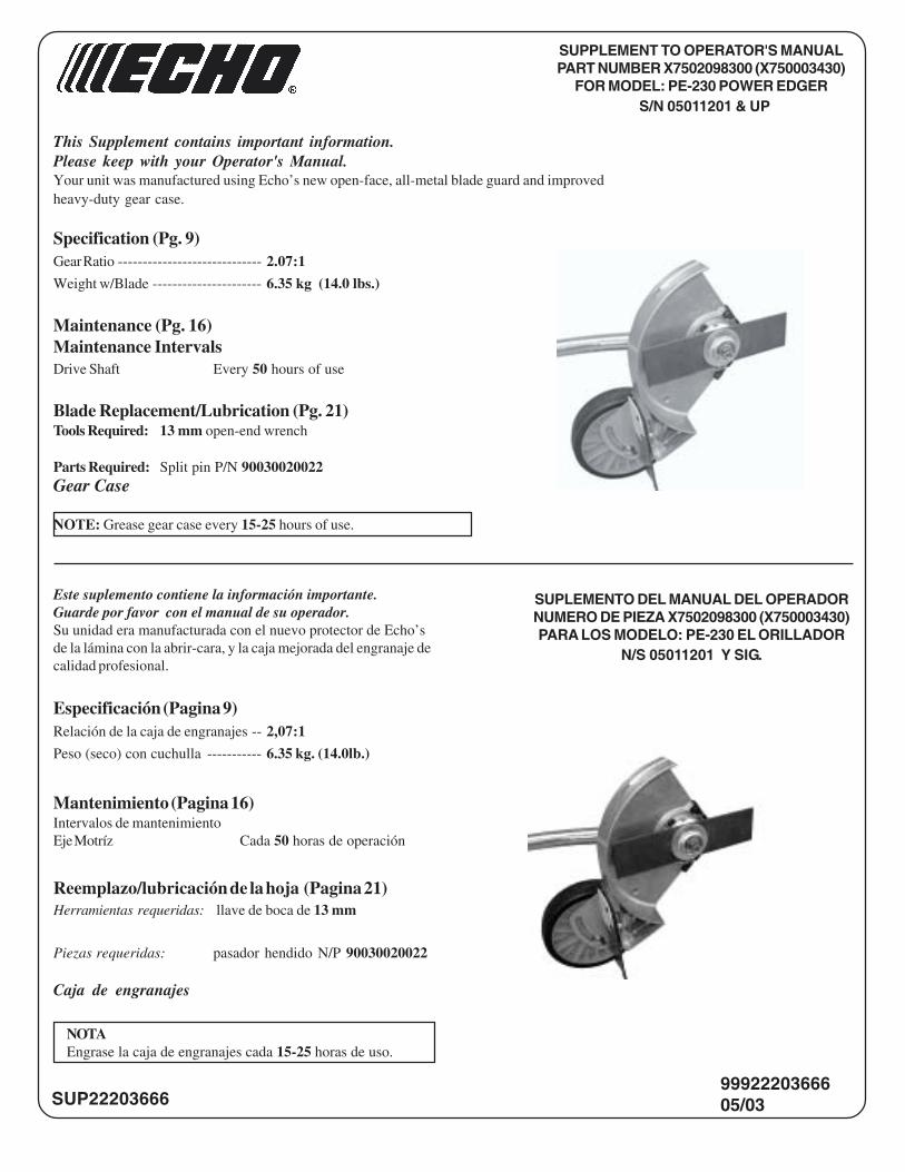
This Supplement contains important information.Please keep with your Operator's Manual.Your unit was manufactured using Echo�s new open-face, all-metal blade guard and improvedheavy-duty gear case.
9992220366605/03SUP22203666
Parts Required: Split pin P/N 90030020022Gear Case
NOTE: Grease gear case every 15-25 hours of use.
Especificación (Pagina 9)Relación de la caja de engranajes -- 2,07:1
Peso (seco) con cuchulla ----------- 6.35 kg. (14.0lb.)
Mantenimiento (Pagina 16)Intervalos de mantenimientoEje Motríz Cada 50 horas de operación
Reemplazo/lubricación de la hoja (Pagina 21)Herramientas requeridas: llave de boca de 13 mm
Piezas requeridas: pasador hendido N/P 90030020022
Caja de engranajes
NOTAEngrase la caja de engranajes cada 15-25 horas de uso.
Este suplemento contiene la información importante.Guarde por favor con el manual de su operador.Su unidad era manufacturada con el nuevo protector de Echo�sde la lámina con la abrir-cara, y la caja mejorada del engranaje decalidad profesional.
SUPLEMENTO DEL MANUAL DEL OPERADORNUMERO DE PIEZA X7502098300 (X750003430)PARA LOS MODELO: PE-230 EL ORILLADOR
N/S 05011201 Y SIG.