Hire andrentals air conditioners and portable air conditioners
Power Conditioners — product guide
table of contents
constant Voltage ferroresonant Power conditioners 1
oPerating characteristics 3
cVs hardwired series 5
Mcr hardwired series 6
Mcr Portable series 8
electrical connections 9
Model coMParison — sPecifications 11
solatron™ Plus series - three Phase Power conditioners 12
1
constant Voltage ferroresonant Power conditioners
Sola’s ferroresonant power conditioners protect equipment from all power problems other than a complete loss of power. They excel at tightly regulating voltage within ±1.0% for input variations up to +10%/-20%, provide superior noise attenuation and are designed to withstand the harshest electrical environments. With no moving parts, Sola’s ferroresonant power conditioners are virtually maintenance free.
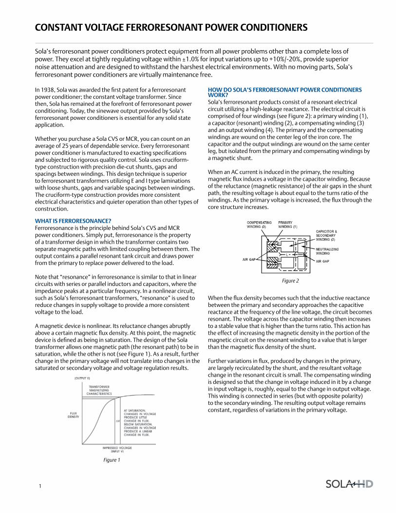
how do sola’s ferroresonant Power conditioners work?Sola’s ferroresonant products consist of a resonant electrical circuit utilizing a high-leakage reactance. The electrical circuit is comprised of four windings (see Figure 2): a primary winding (1), a capacitor (resonant) winding (2), a compensating winding (3) and an output winding (4). The primary and the compensating windings are wound on the center leg of the iron core. The capacitor and the output windings are wound on the same center leg, but isolated from the primary and compensating windings by a magnetic shunt.
When an AC current is induced in the primary, the resulting magnetic flux induces a voltage in the capacitor winding. Because of the reluctance (magnetic resistance) of the air gaps in the shunt path, the resulting voltage is about equal to the turns ratio of the windings. As the primary voltage is increased, the flux through the core structure increases.
When the flux density becomes such that the inductive reactance between the primary and secondary approaches the capacitive reactance at the frequency of the line voltage, the circuit becomes resonant. The voltage across the capacitor winding then increases to a stable value that is higher than the turns ratio. This action has the effect of increasing the magnetic density in the portion of the magnetic circuit on the resonant winding to a value that is larger than the magnetic flux density of the shunt.
Further variations in flux, produced by changes in the primary, are largely recirculated by the shunt, and the resultant voltage change in the resonant circuit is small. The compensating winding is designed so that the change in voltage induced in it by a change in input voltage is, roughly, equal to the change in output voltage. This winding is connected in series (but with opposite polarity) to the secondary winding. The resulting output voltage remains constant, regardless of variations in the primary voltage.
In 1938, Sola was awarded the first patent for a ferroresonant power conditioner; the constant voltage transformer. Since then, Sola has remained at the forefront of ferroresonant power conditioning. Today, the sinewave output provided by Sola’s ferroresonant power conditioners is essential for any solid state application.
Whether you purchase a Sola CVS or MCR, you can count on an average of 25 years of dependable service. Every ferroresonant power conditioner is manufactured to exacting specifications and subjected to rigorous quality control. Sola uses cruciform-type construction with precision die-cut shunts, gaps and spacings between windings. This design technique is superior to ferroresonant transformers utilizing E and I type laminations with loose shunts, gaps and variable spacings between windings. The cruciform-type construction provides more consistent electrical characteristics and quieter operation than other types of construction.
what is ferroresonance?Ferroresonance is the principle behind Sola’s CVS and MCR power conditioners. Simply put, ferroresonance is the property of a transformer design in which the transformer contains two separate magnetic paths with limited coupling between them. The output contains a parallel resonant tank circuit and draws power from the primary to replace power delivered to the load.
Note that “resonance” in ferroresonance is similar to that in linear circuits with series or parallel inductors and capacitors, where the impedance peaks at a particular frequency. In a nonlinear circuit, such as Sola’s ferroresonant transformers, “resonance” is used to reduce changes in supply voltage to provide a more consistent voltage to the load.
A magnetic device is nonlinear. Its reluctance changes abruptly above a certain magnetic flux density. At this point, the magnetic device is defined as being in saturation. The design of the Sola transformer allows one magnetic path (the resonant path) to be in saturation, while the other is not (see Figure 1). As a result, further change in the primary voltage will not translate into changes in the saturated or secondary voltage and voltage regulation results.
Figure 1
Figure 2
2
constant Voltage ferroresonant Power conditioners
harMonic blockingThe input current to a ferroresonant transformer contains a negligible harmonic current relative to the fundamental. This relationship remains about the same no matter what kind of load is placed on the output winding. Even switch-mode power supplies that may demand harmonic currents as high as 150% relative to the fundamental will reflect near sine wave currents back to the utility. This is due to the blocking action of the two separate magnetic paths of the ferroresonant transformer.
ferroresonant Power conditioners and harMonicsA Sola ferroresonant power conditioner will have essentially harmonic free output because of the addition of a neutralizing coil. This coil neutralizes the harmonics in a manner best explained by first considering the device as a conventional transformer with the neutralizing coil disconnected. Though this coil is now open circuited, it has a voltage induced in it as a portion of the magnetic flux passes through the center leg of the core to the outer legs. Since some of the primary flux links this coil, fundamental voltage is present. The resultant voltage has a high odd-harmonic content due to the leakage flux from the output winding.
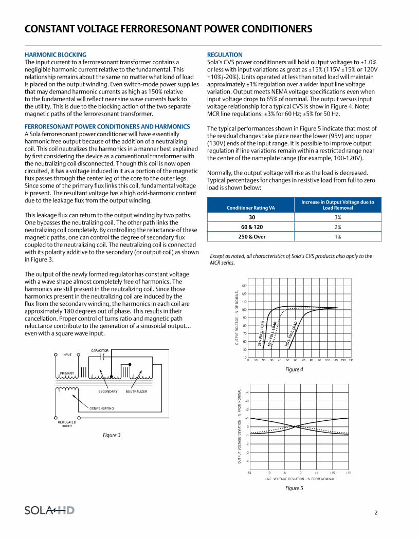
This leakage flux can return to the output winding by two paths. One bypasses the neutralizing coil. The other path links the neutralizing coil completely. By controlling the reluctance of these magnetic paths, one can control the degree of secondary flux coupled to the neutralizing coil. The neutralizing coil is connected with its polarity additive to the secondary (or output coil) as shown in Figure 3.
The output of the newly formed regulator has constant voltage with a wave shape almost completely free of harmonics. The harmonics are still present in the neutralizing coil. Since those harmonics present in the neutralizing coil are induced by the flux from the secondary winding, the harmonics in each coil are approximately 180 degrees out of phase. This results in their cancellation. Proper control of turns ratio and magnetic path reluctance contribute to the generation of a sinusoidal output... even with a square wave input.
Figure 3
regulationSola’s CVS power conditioners will hold output voltages to ±1.0% or less with input variations as great as ±15% (115V ±15% or 120V +10%/-20%). Units operated at less than rated load will maintain approximately ±1% regulation over a wider input line voltage variation. Output meets NEMA voltage specifications even when input voltage drops to 65% of nominal. The output versus input voltage relationship for a typical CVS is show in Figure 4. Note: MCR line regulations: ±3% for 60 Hz; ±5% for 50 Hz.
The typical performances shown in Figure 5 indicate that most of the residual changes take place near the lower (95V) and upper (130V) ends of the input range. It is possible to improve output regulation if line variations remain within a restricted range near the center of the nameplate range (for example, 100-120V).
Normally, the output voltage will rise as the load is decreased. Typical percentages for changes in resistive load from full to zero load is shown below:
conditioner rating Vaincrease in output Voltage due to
load removal
30 3%
60 & 120 2%
250 & over 1%
Except as noted, all characteristics of Sola’s CVS products also apply to the MCR series.
Figure 4
Figure 5
3
oPerating characteristics
Power factor
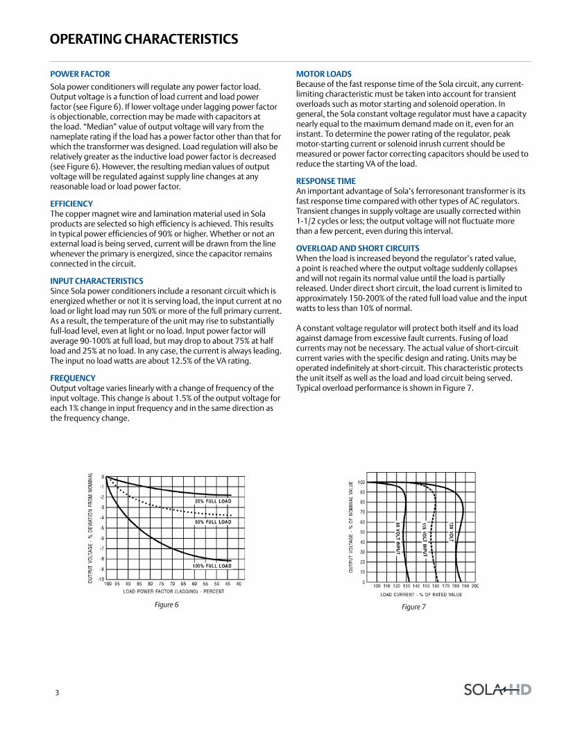
Sola power conditioners will regulate any power factor load. Output voltage is a function of load current and load power factor (see Figure 6). If lower voltage under lagging power factor is objectionable, correction may be made with capacitors at the load. “Median” value of output voltage will vary from the nameplate rating if the load has a power factor other than that for which the transformer was designed. Load regulation will also be relatively greater as the inductive load power factor is decreased (see Figure 6). However, the resulting median values of output voltage will be regulated against supply line changes at any reasonable load or load power factor.
efficiencyThe copper magnet wire and lamination material used in Sola products are selected so high efficiency is achieved. This results in typical power efficiencies of 90% or higher. Whether or not an external load is being served, current will be drawn from the line whenever the primary is energized, since the capacitor remains connected in the circuit.
inPut characteristicsSince Sola power conditioners include a resonant circuit which is energized whether or not it is serving load, the input current at no load or light load may run 50% or more of the full primary current. As a result, the temperature of the unit may rise to substantially full-load level, even at light or no load. Input power factor will average 90-100% at full load, but may drop to about 75% at half load and 25% at no load. In any case, the current is always leading. The input no load watts are about 12.5% of the VA rating.
frequencyOutput voltage varies linearly with a change of frequency of the input voltage. This change is about 1.5% of the output voltage for each 1% change in input frequency and in the same direction as the frequency change.
Motor loadsBecause of the fast response time of the Sola circuit, any current-limiting characteristic must be taken into account for transient overloads such as motor starting and solenoid operation. In general, the Sola constant voltage regulator must have a capacity nearly equal to the maximum demand made on it, even for an instant. To determine the power rating of the regulator, peak motor-starting current or solenoid inrush current should be measured or power factor correcting capacitors should be used to reduce the starting VA of the load.
resPonse tiMeAn important advantage of Sola’s ferroresonant transformer is its fast response time compared with other types of AC regulators. Transient changes in supply voltage are usually corrected within 1-1/2 cycles or less; the output voltage will not fluctuate more than a few percent, even during this interval.
oVerload and short circuitsWhen the load is increased beyond the regulator’s rated value, a point is reached where the output voltage suddenly collapses and will not regain its normal value until the load is partially released. Under direct short circuit, the load current is limited to approximately 150-200% of the rated full load value and the input watts to less than 10% of normal.
A constant voltage regulator will protect both itself and its load against damage from excessive fault currents. Fusing of load currents may not be necessary. The actual value of short-circuit current varies with the specific design and rating. Units may be operated indefinitely at short-circuit. This characteristic protects the unit itself as well as the load and load circuit being served. Typical overload performance is shown in Figure 7.
Figure 6 Figure 7

4
oPerating characteristics
teMPeratureSola’s ferroresonant power conditioners are very stable with respect to temperature. The change in output voltage is only 0.025% per degree centigrade. Units are factory adjusted to +2%/-0% of nominal, with full load and nominal input voltage. This adjustment to the high side of nominal is to compensate for the natural temperature drift of about 1% that takes place during initial turn-on or warm-up. When the unit warms up to operating temperature, the voltage typically falls about 1%.
At a stable operating temperature, the output voltage will change slightly with varying ambient temperatures. This shift is equal to approximately 1% for each 40°C of temperature change.
The normal maximum temperature rise of a Sola power conditioner may fall anywhere in the range of 40°C to 110°C depending on the type and rating. The nominal design ambient range is between -20°C and +50°C (-20°C to +40°C for 70 - 1000 VA, 60 Hz portable models).
external Magnetic fieldIn almost all applications, this effect may be disregarded. The exclusive Sola “wide outside leg” construction (U.S. Patent 2,806,199) reduces stray magnetic fields to a practical minimum. On critical applications, care should be taken in orientation of the core with respect to critical circuits to minimize the effect of the field.
Phase shiftThe phase difference which exists between input and output voltages is in the range of 120 degrees to 140 degrees at full load. This phase difference varies with the magnitude and power factor of the load, and to a lesser extent, with changes in line voltage and load power factor.
Parallel oPeration Constant voltage regulators of the same Sola catalog number may be connected in parallel to obtain larger load capacity. Both input and output connections must be made in parallel. See Figure 8.
1. The catalog number must end in -8 and must be larger than the 1 KVA. Any units with 7-digit model numbers (no dash) or are not -8 cannot be paralleled. Portable units cannot be paralleled.
2. On 60 Hz models smaller than 5 KVA, do not parallel connect the 208 or 240 volt windings.
3. On 50 Hz models, do not parallel connect the 220 volt center tap outputs and the 240 volt center tap outputs.
4. All input and output paralleling wires must be tied in an external paralleling “box”. Do not attempt to jumper the wires of one unit to the terminal block of the other unit. The terminal block is not rated to carry the currents of both units.
5. The input of each unit must be properly fused separately.
6. Failure to adhere to all of these requirements may damage the output windings.
Figure 8

5
cVs hardwired series
grouP 1 – cVs series, 60 hz
Va catalog number Voltage inputVoltage output
height in (mm)
width in (mm)
depth in (mm)
ship weight lbs (kg)
design style
elec conn
30 23-13-030-2 120 120 7.00 (177.8) 4.00 (101.6) 5.00 (127.0) 9.0 (4.08) 1 J
60 23-13-060-2 120 120 7.00 (177.8) 4.00 (101.6) 5.00 (127.0) 9.0 (4.08) 1 J
120 23-22-112-2 120, 240 120 8.00 (203.2) 4.00 (101.6) 5.00 (127.0) 13.0 (5.90) 1 J
250 23-23-125-8 120, 240, 480 120 11.00 (279.4) 6.00 (152.4) 8.00 (203.2) 29.0 (13.15) 1 G
500 23-23-150-8 120, 208, 240, 480 120, 240 13.00 (330.2) 9.00 (228.6) 7.00 (177.8) 42.0 (19.05) 1 H
1000 23-23-210-8 120, 208, 240, 480 120, 240 17.00 (431.8) 9.00 (228.6) 7.00 (177.8) 65.0 (29.48) 1 H
2000 23-23-220-8 120, 208, 240, 480 120, 240 18.00 (457.2) 13.00 (330.2) 10.00 (254.0) 111.0 (50.35) 1 H
3000 23-23-230-8 120, 208, 240, 480 120, 240 19.00 (482.6) 13.00 (330.2) 10.00 (254.0) 142.0 (64.41) 1 H
5000 23-23-250-8 120, 208, 240, 480 120, 240 28.00 (711.2) 13.00 (330.2) 10.00 (254.0) 222.0 (100.70) 1 H
7500* 23-28-275-6 240, 480 120, 240 27.00 (685.8) 25.00 (635.0) 9.00 (228.6) 365.0 (165.56) 2 J
* This unit is Listed only.
selection tables: single Phase
Superior voltage regulation of ±1% sets the CVS series apart from other power conditioning technologies on the market. Extremely tight regulation is accomplished by SolaHD’s ferroresonant transformer technology. The CVS recreates a well regulated sinusoidal waveform that is well isolated from input disturbances including:
• Impulses • Swells
• Brownouts • Sags
• Severe waveform distortion
No other power conditioning technology provides as complete a solution against these power quality disturbances. The CVS series is ideal for applications where even a small change in voltage level can lead to unscheduled downtime, misoperation, incorrect data or scrapped production.
aPPlications
• Industrial automation and control equipment PLCs
• Analytical laboratory and factory automating equipment
• Photo processing equipment
• Sound/recording systems
• Photographic enlargers
• Broadcast equipment
features
• Superior voltage regulation of ±1%
• Surge protection tested to ANSI/IEEE C62.41, Class A & B waveform
• Harmonic filtering
• Hardwired
• Acts as a step-up/step-down transformer
• Galvanic isolation provides exceptional circuit protection
• 25 year typical mean time between failure
• No maintenance required
certifications and coMPliances
• Listed
- UL 1012
- CSA C22.2 No. 107.1
• RoHS Compliant
related Products
• On-line UPS (S4K Industrial)
• Surge Protection
• Three Phase Power Conditioners
• Active Tracking® Filters
E47379
6
Mcr hardwired series
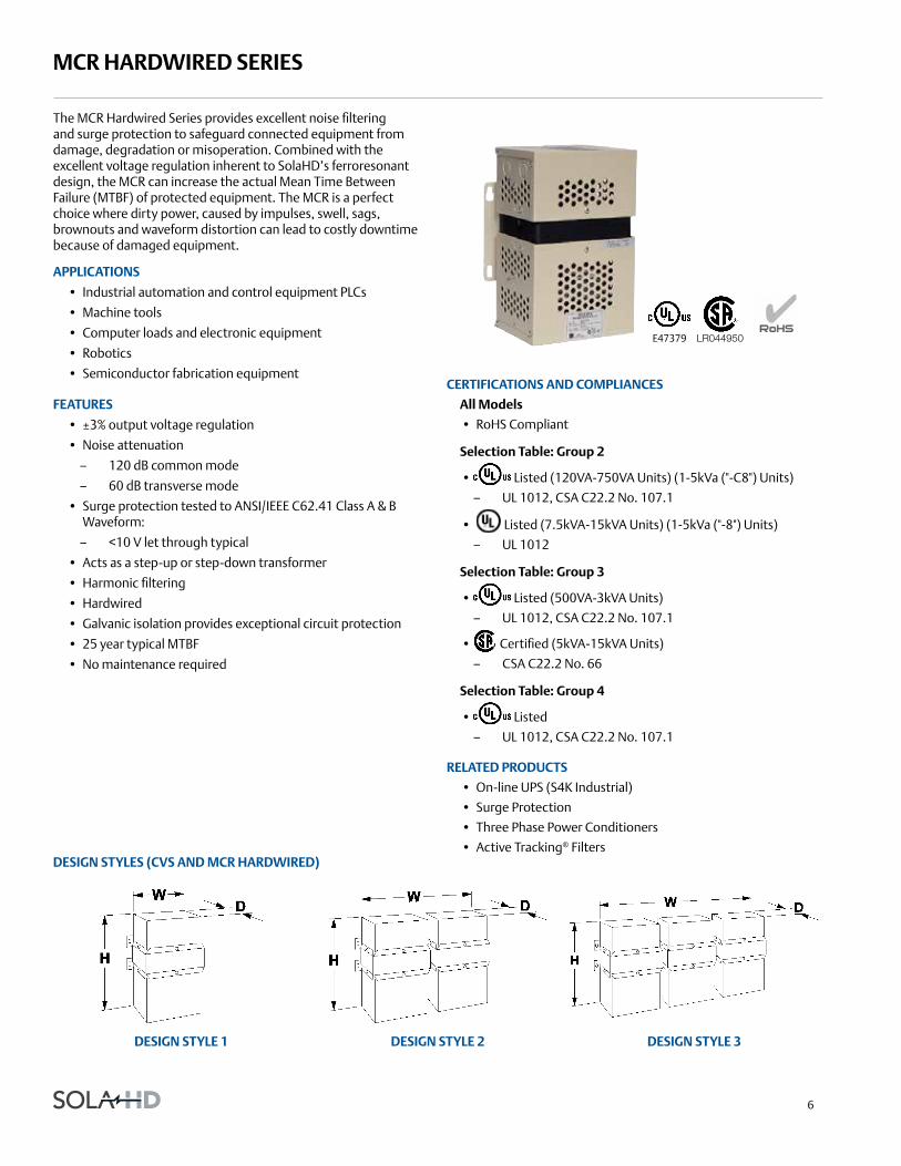
The MCR Hardwired Series provides excellent noise filtering and surge protection to safeguard connected equipment from damage, degradation or misoperation. Combined with the excellent voltage regulation inherent to SolaHD’s ferroresonant design, the MCR can increase the actual Mean Time Between Failure (MTBF) of protected equipment. The MCR is a perfect choice where dirty power, caused by impulses, swell, sags, brownouts and waveform distortion can lead to costly downtime because of damaged equipment.
aPPlications
• Industrial automation and control equipment PLCs
• Machine tools
• Computer loads and electronic equipment
• Robotics
• Semiconductor fabrication equipment
features
• ±3% output voltage regulation
• Noise attenuation
– 120 dB common mode
– 60 dB transverse mode
• Surge protection tested to ANSI/IEEE C62.41 Class A & B Waveform:
– <10 V let through typical
• Acts as a step-up or step-down transformer
• Harmonic filtering
• Hardwired
• Galvanic isolation provides exceptional circuit protection
• 25 year typical MTBF
• No maintenance required
design styles (cVs and Mcr hardwired)
design style 1 design style 2 design style 3
E47379 LR044950
certifications and coMPliances
all Models
• RoHS Compliant
selection table: group 2
• Listed (120VA-750VA Units) (1-5kVa ("-C8") Units)
– UL 1012, CSA C22.2 No. 107.1
• Listed (7.5kVA-15kVA Units) (1-5kVa ("-8") Units)
– UL 1012
selection table: group 3
• Listed (500VA-3kVA Units)
– UL 1012, CSA C22.2 No. 107.1
• Certified (5kVA-15kVA Units)
– CSA C22.2 No. 66
selection table: group 4
• Listed
– UL 1012, CSA C22.2 No. 107.1
related Products
• On-line UPS (S4K Industrial)
• Surge Protection
• Three Phase Power Conditioners
• Active Tracking® Filters
7
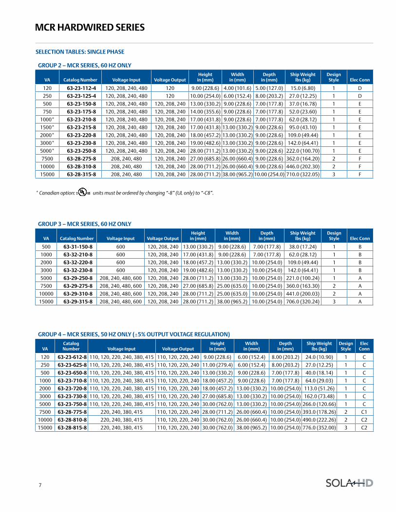
Mcr hardwired series
grouP 2 – Mcr series, 60 hz only
Va catalog number Voltage input Voltage outputheight
in (mm)width
in (mm)depth
in (mm)ship weight
lbs (kg)design
style elec conn
120 63-23-112-4 120, 208, 240, 480 120 9.00 (228.6) 4.00 (101.6) 5.00 (127.0) 15.0 (6.80) 1 D
250 63-23-125-4 120, 208, 240, 480 120 10.00 (254.0) 6.00 (152.4) 8.00 (203.2) 27.0 (12.25) 1 D
500 63-23-150-8 120, 208, 240, 480 120, 208, 240 13.00 (330.2) 9.00 (228.6) 7.00 (177.8) 37.0 (16.78) 1 E
750 63-23-175-8 120, 208, 240, 480 120, 208, 240 14.00 (355.6) 9.00 (228.6) 7.00 (177.8) 52.0 (23.60) 1 E
1000* 63-23-210-8 120, 208, 240, 480 120, 208, 240 17.00 (431.8) 9.00 (228.6) 7.00 (177.8) 62.0 (28.12) 1 E
1500* 63-23-215-8 120, 208, 240, 480 120, 208, 240 17.00 (431.8) 13.00 (330.2) 9.00 (228.6) 95.0 (43.10) 1 E
2000* 63-23-220-8 120, 208, 240, 480 120, 208, 240 18.00 (457.2) 13.00 (330.2) 9.00 (228.6) 109.0 (49.44) 1 E
3000* 63-23-230-8 120, 208, 240, 480 120, 208, 240 19.00 (482.6) 13.00 (330.2) 9.00 (228.6) 142.0 (64.41) 1 E
5000* 63-23-250-8 120, 208, 240, 480 120, 208, 240 28.00 (711.2) 13.00 (330.2) 9.00 (228.6) 222.0 (100.70) 1 E
7500 63-28-275-8 208, 240, 480 120, 208, 240 27.00 (685.8) 26.00 (660.4) 9.00 (228.6) 362.0 (164.20) 2 F
10000 63-28-310-8 208, 240, 480 120, 208, 240 28.00 (711.2) 26.00 (660.4) 9.00 (228.6) 446.0 (202.30) 2 F
15000 63-28-315-8 208, 240, 480 120, 208, 240 28.00 (711.2) 38.00 (965.2) 10.00 (254.0) 710.0 (322.05) 3 F
* Canadian option: units must be ordered by changing “-8” (UL only) to “-C8”.
grouP 3 – Mcr series, 60 hz only
Va catalog number Voltage input Voltage outputheight
in (mm)width
in (mm)depth
in (mm)ship weight
lbs (kg)design
style elec conn
500 63-31-150-8 600 120, 208, 240 13.00 (330.2) 9.00 (228.6) 7.00 (177.8) 38.0 (17.24) 1 B
1000 63-32-210-8 600 120, 208, 240 17.00 (431.8) 9.00 (228.6) 7.00 (177.8) 62.0 (28.12) 1 B
2000 63-32-220-8 600 120, 208, 240 18.00 (457.2) 13.00 (330.2) 10.00 (254.0) 109.0 (49.44) 1 B
3000 63-32-230-8 600 120, 208, 240 19.00 (482.6) 13.00 (330.2) 10.00 (254.0) 142.0 (64.41) 1 B
5000 63-29-250-8 208, 240, 480, 600 120, 208, 240 28.00 (711.2) 13.00 (330.2) 10.00 (254.0) 221.0 (100.24) 1 A
7500 63-29-275-8 208, 240, 480, 600 120, 208, 240 27.00 (685.8) 25.00 (635.0) 10.00 (254.0) 360.0 (163.30) 2 A
10000 63-29-310-8 208, 240, 480, 600 120, 208, 240 28.00 (711.2) 25.00 (635.0) 10.00 (254.0) 441.0 (200.03) 2 A
15000 63-29-315-8 208, 240, 480, 600 120, 208, 240 28.00 (711.2) 38.00 (965.2) 10.00 (254.0) 706.0 (320.24) 3 A
grouP 4 – Mcr series, 50 hz only (±5% outPut Voltage regulation)
Vacatalog number Voltage input Voltage output
height in (mm)
width in (mm)
depth in (mm)
ship weight lbs (kg)
design style
elec conn
120 63-23-612-8 110, 120, 220, 240, 380, 415 110, 120, 220, 240 9.00 (228.6) 6.00 (152.4) 8.00 (203.2) 24.0 (10.90) 1 C
250 63-23-625-8 110, 120, 220, 240, 380, 415 110, 120, 220, 240 11.00 (279.4) 6.00 (152.4) 8.00 (203.2) 27.0 (12.25) 1 C
500 63-23-650-8 110, 120, 220, 240, 380, 415 110, 120, 220, 240 13.00 (330.2) 9.00 (228.6) 7.00 (177.8) 40.0 (18.14) 1 C
1000 63-23-710-8 110, 120, 220, 240, 380, 415 110, 120, 220, 240 18.00 (457.2) 9.00 (228.6) 7.00 (177.8) 64.0 (29.03) 1 C
2000 63-23-720-8 110, 120, 220, 240, 380, 415 110, 120, 220, 240 18.00 (457.2) 13.00 (330.2) 10.00 (254.0) 113.0 (51.26) 1 C
3000 63-23-730-8 110, 120, 220, 240, 380, 415 110, 120, 220, 240 27.00 (685.8) 13.00 (330.2) 10.00 (254.0) 162.0 (73.48) 1 C
5000 63-23-750-8 110, 120, 220, 240, 380, 415 110, 120, 220, 240 30.00 (762.0) 13.00 (330.2) 10.00 (254.0) 266.0 (120.66) 1 C
7500 63-28-775-8 220, 240, 380, 415 110, 120, 220, 240 28.00 (711.2) 26.00 (660.4) 10.00 (254.0) 393.0 (178.26) 2 C1
10000 63-28-810-8 220, 240, 380, 415 110, 120, 220, 240 30.00 (762.0) 26.00 (660.4) 10.00 (254.0) 490.0 (222.26) 2 C2
15000 63-28-815-8 220, 240, 380, 415 110, 120, 220, 240 30.00 (762.0) 38.00 (965.2) 10.00 (254.0) 776.0 (352.00) 3 C2
selection tables: single Phase
8
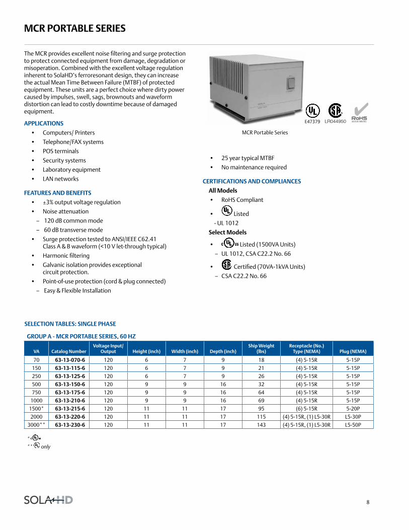
Mcr Portable series
The MCR provides excellent noise filtering and surge protection to protect connected equipment from damage, degradation or misoperation. Combined with the excellent voltage regulation inherent to SolaHD’s ferroresonant design, they can increase the actual Mean Time Between Failure (MTBF) of protected equipment. These units are a perfect choice where dirty power caused by impulses, swell, sags, brownouts and waveform distortion can lead to costly downtime because of damaged equipment.
aPPlications
• Computers/ Printers
• Telephone/FAX systems
• POS terminals
• Security systems
• Laboratory equipment
• LAN networks
features and benefits
• ±3% output voltage regulation
• Noise attenuation
– 120 dB common mode
– 60 dB transverse mode
• Surge protection tested to ANSI/IEEE C62.41 Class A & B waveform (<10 V let-through typical)
• Harmonic filtering
• Galvanic isolation provides exceptional circuit protection.
• Point-of-use protection (cord & plug connected)
– Easy & Flexible Installation
grouP a - Mcr Portable series, 60 hz
Va catalog numberVoltage input/
output height (inch) width (inch) depth (inch)ship weight
(lbs)receptacle (no.)
type (neMa) Plug (neMa)
70 63-13-070-6 120 6 7 9 18 (4) 5-15R 5-15P
150 63-13-115-6 120 6 7 9 21 (4) 5-15R 5-15P
250 63-13-125-6 120 6 7 9 26 (4) 5-15R 5-15P
500 63-13-150-6 120 9 9 16 32 (4) 5-15R 5-15P
750 63-13-175-6 120 9 9 16 64 (4) 5-15R 5-15P
1000 63-13-210-6 120 9 9 16 69 (4) 5-15R 5-15P
1500* 63-13-215-6 120 11 11 17 95 (6) 5-15R 5-20P
2000 63-13-220-6 120 11 11 17 115 (4) 5-15R, (1) L5-30R L5-30P
3000** 63-13-230-6 120 11 11 17 143 (4) 5-15R, (1) L5-30R L5-50P
* ** only
selection tables: single Phase
• 25 year typical MTBF
• No maintenance required
certifications and coMPliances
all Models
• RoHS Compliant
• Listed
- UL 1012
select Models
• Listed (1500VA Units)
– UL 1012, CSA C22.2 No. 66
• Certified (70VA-1kVA Units)
– CSA C22.2 No. 66
MCR Portable Series
E47379 LR044950
9
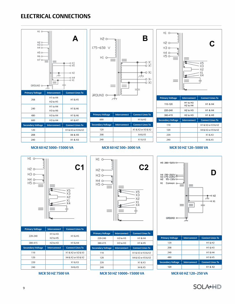
electrical connections
Primary Voltage interconnect connect lines to
208H1 to H4
H2 to H5H1 & H5
240H1 to H4
H3 to H6H1 & H6
480 H3 to H4 H1 & H6
600 H3 to H4 H1 & H7
secondary Voltage interconnect connect lines to
120 X1 & X2 or X3 & X2
208 X4 & X5
240 X1 & X3
Primary Voltage interconnect connect lines to
600 H1 & H2
secondary Voltage interconnect connect lines to
120 X1 & X2 or X3 & X2
208 X4 & X5
240 X1 & X3
Primary Voltage interconnect connect lines to
110-120 H1 to H3H2 to H4 H1 & H4
220-240 H2 to H3 H1 & H4
380-415 H2 to H3 H1 & H5
secondary Voltage interconnect connect lines to
110 X1 & X2 or X3 & X2
120 X4 & X2 or X5 & X2
220 X1 & X3
240 X4 & X5
Primary Voltage interconnect connect lines to
220-240H1 to H3
H2 to H5 H1 & H5
380-415 H2 to H3 H1 & H4
secondary Voltage interconnect connect lines to
110 X1 & X2 or X2 & X3
120 X4 & X2 or X5 & X2
220 X1 & X3
240 X4 & X5
Primary Voltage interconnect connect lines to
220-240 H2 to H3 H1 & H4
380-415 H2 to H3 H1 & H5
secondary Voltage interconnect connect lines to
110 X1 & X2 or X3 & X2
120 X4 & X2 or X5 & X2
220 X1 & X3
240 X4 & X5
Primary Voltage interconnect connect lines to
120 H1 & H2
208 H1 & H3
240 H1 & H4
480 H1 & H5
secondary Voltage interconnect connect lines to
120 X1 & X2
Mcr 60 hz 5000–15000 Va Mcr 60 hz 500–3000 Va Mcr 50 hz 120–5000 Va
Mcr 50 hz 7500 Va Mcr 50 hz 10000–15000 Va Mcr 60 hz 120–250 Va
BC
C1 C2 D
A
10
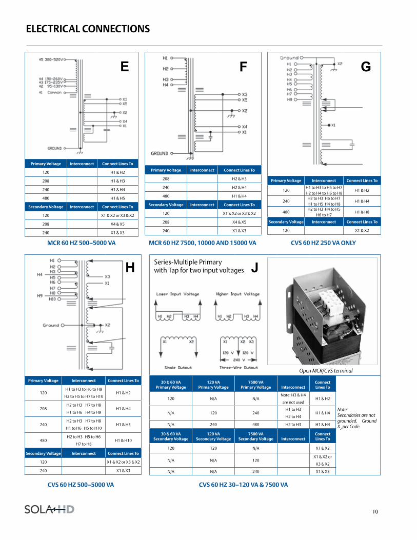
electrical connections
Primary Voltage interconnect connect lines to
120H1 to H3 to H6 to H8
H2 to H5 to H7 to H10H1 & H2
208H2 to H3 H7 to H8
H1 to H6 H4 to H9H1 & H4
240H2 to H3 H7 to H8
H1 to H6 H5 to H10H1 & H5
480H2 to H3 H5 to H6
H7 to H8H1 & H10
secondary Voltage interconnect connect lines to
120 X1 & X2 or X3 & X2
240 X1 & X3
30 & 60 Va Primary Voltage
120 Va Primary Voltage
7500 Va Primary Voltage interconnect
connect lines to
120 N/A N/ANote: H3 & H4
are not usedH1 & H2
N/A 120 240H1 to H3
H2 to H4H1 & H4
N/A 240 480 H2 to H3 H1 & H4
30 & 60 Va secondary Voltage
120 Va secondary Voltage
7500 Va secondary Voltage interconnect
connect lines to
120 120 N/A X1 & X2
N/A N/A 120X1 & X2 or
X3 & X2
N/A N/A 240 X1 & X3
Primary Voltage interconnect connect lines to
120H1 to H3 to H5 to H7 H2 to H4 to H6 to H8
H1 & H2
240H2 to H3 H6 to H7 H1 to H5 H4 to H8
H1 & H4
480H2 to H3 H4 to H5
H6 to H7 H1 & H8
secondary Voltage interconnect connect lines to
120 X1 & X2
Primary Voltage interconnect connect lines to
120 H1 & H2
208 H1 & H3
240 H1 & H4
480 H1 & H5
secondary Voltage interconnect connect lines to
120 X1 & X2 or X3 & X2
208 X4 & X5
240 X1 & X3
Mcr 60 hz 500–5000 Va Mcr 60 hz 7500, 10000 and 15000 Va cVs 60 hz 250 Va only
cVs 60 hz 500–5000 Va
E F G
H JSeries-Multiple Primarywith Tap for two input voltages
cVs 60 hz 30–120 Va & 7500 Va
Note: Secondaries are not grounded. Ground X2 per Code.
Open MCR/CVS terminal
Primary Voltage interconnect connect lines to
208 H2 & H3
240 H2 & H4
480 H1 & H4
secondary Voltage interconnect connect lines to
120 X1 & X2 or X3 & X2
208 X4 & X5
240 X1 & X3
11
sPecifications
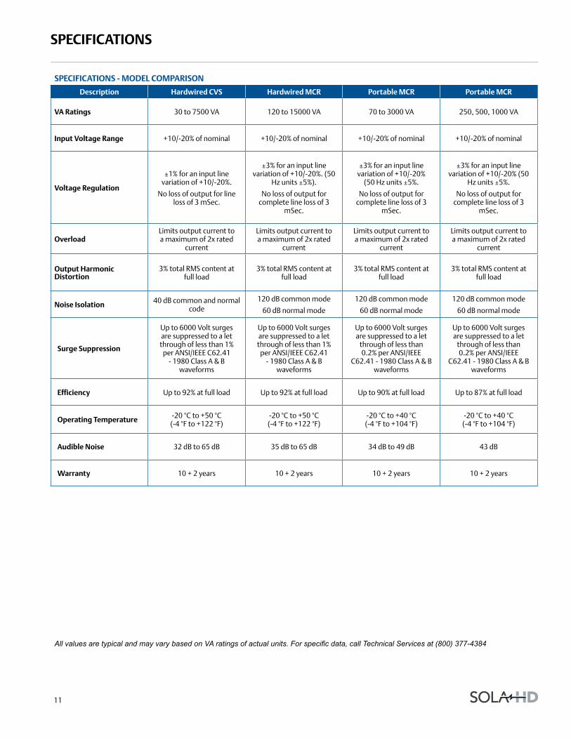
sPecifications - Model coMParison
description hardwired cVs hardwired Mcr Portable Mcr Portable Mcr
Va ratings 30 to 7500 VA 120 to 15000 VA 70 to 3000 VA 250, 500, 1000 VA
input Voltage range +10/-20% of nominal +10/-20% of nominal +10/-20% of nominal +10/-20% of nominal
Voltage regulation
±1% for an input line variation of +10/-20%.
No loss of output for line loss of 3 mSec.
±3% for an input line variation of +10/-20%. (50
Hz units ±5%).
No loss of output for complete line loss of 3
mSec.
±3% for an input line variation of +10/-20%
(50 Hz units ±5%.
No loss of output for complete line loss of 3
mSec.
±3% for an input line variation of +10/-20% (50
Hz units ±5%.
No loss of output for complete line loss of 3
mSec.
overloadLimits output current to a maximum of 2x rated
current
Limits output current to a maximum of 2x rated
current
Limits output current to a maximum of 2x rated
current
Limits output current to a maximum of 2x rated
current
output harmonic distortion
3% total RMS content at full load
3% total RMS content at full load
3% total RMS content at full load
3% total RMS content at full load
noise isolation 40 dB common and normal code
120 dB common mode
60 dB normal mode
120 dB common mode
60 dB normal mode
120 dB common mode
60 dB normal mode
surge suppression
Up to 6000 Volt surges are suppressed to a let through of less than 1%
per ANSI/IEEE C62.41 - 1980 Class A & B
waveforms
Up to 6000 Volt surges are suppressed to a let through of less than 1%
per ANSI/IEEE C62.41 - 1980 Class A & B
waveforms
Up to 6000 Volt surges are suppressed to a let
through of less than 0.2% per ANSI/IEEE
C62.41 - 1980 Class A & B waveforms
Up to 6000 Volt surges are suppressed to a let
through of less than 0.2% per ANSI/IEEE
C62.41 - 1980 Class A & B waveforms
efficiency Up to 92% at full load Up to 92% at full load Up to 90% at full load Up to 87% at full load
operating temperature -20 °C to +50 °C (-4 °F to +122 °F)
-20 °C to +50 °C (-4 °F to +122 °F)
-20 °C to +40 °C (-4 °F to +104 °F)
-20 °C to +40 °C (-4 °F to +104 °F)
audible noise 32 dB to 65 dB 35 dB to 65 dB 34 dB to 49 dB 43 dB
warranty 10 + 2 years 10 + 2 years 10 + 2 years 10 + 2 years
All values are typical and may vary based on VA ratings of actual units. For specific data, call Technical Services at (800) 377-4384
12
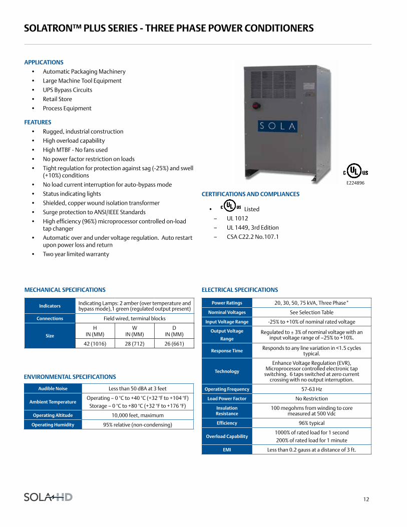
solatron™ Plus series - three Phase Power conditioners
aPPlications
• Automatic Packaging Machinery
• Large Machine Tool Equipment
• UPS Bypass Circuits
• Retail Store
• Process Equipment
features
• Rugged, industrial construction
• High overload capability
• High MTBF - No fans used
• No power factor restriction on loads
• Tight regulation for protection against sag (-25%) and swell (+10%) conditions
• No load current interruption for auto-bypass mode
• Status indicating lights
• Shielded, copper wound isolation transformer
• Surge protection to ANSI/IEEE Standards
• High efficiency (96%) microprocessor controlled on-load tap changer
• Automatic over and under voltage regulation. Auto restart upon power loss and return
• Two year limited warranty
E224896
certifications and coMPliances
• Listed
– UL 1012
– UL 1449, 3rd Edition
– CSA C22.2 No.107.1
audible noise Less than 50 dBA at 3 feet
ambient temperatureOperating – 0 °C to +40 °C (+32 °F to +104 °F)
Storage – 0 °C to +80 °C (+32 °F to +176 °F)
operating altitude 10,000 feet, maximum
operating humidity 95% relative (non-condensing)
Mechanical sPecifications electrical sPecifications
enVironMental sPecifications
Power ratings 20, 30, 50, 75 kVA, Three Phase*
nominal Voltages See Selection Table
input Voltage range -25% to +10% of nominal rated voltage
output Voltage
rangeRegulated to ± 3% of nominal voltage with an
input voltage range of –25% to +10%.
response time Responds to any line variation in <1.5 cycles typical.
technology
Enhance Voltage Regulation (EVR), Microprocessor controlled electronic tap
switching. 6 taps switched at zero current crossing with no output interruption.
operating frequency 57-63 Hz
load Power factor No Restriction
insulation resistance
100 megohms from winding to core measured at 500 Vdc
efficiency 96% typical
overload capability1000% of rated load for 1 second200% of rated load for 1 minute
eMi Less than 0.2 gauss at a distance of 3 ft.
indicators Indicating Lamps: 2 amber (over temperature and bypass mode),1 green (regulated output present)
connections Field wired, terminal blocks
size
H IN (MM)
W IN (MM)
D IN (MM)
42 (1016) 28 (712) 26 (661)

13
solatron™ Plus series - three Phase Power conditioners
selection guide
output kVa catalog number Vac input Vac output ship weight lbs (kg)
208 Vac inPut, 208y/120 Vac outPut, 60 hz20 63taa320 208 208Y/120 600.0 (273.00)
30 63taa330 208 208Y/120 750.0 (341.00)
50 63taa350 208 208Y/120 950.0 (432.00)
75 63taa375 208 208Y/120 1200.0 (545.00)
480 Vac inPut, 208y/120 Vac outPut, 60 hz20 63tca320 480 208Y/120 600.0 (273.00)
30 63tca330 480 208Y/120 750.0 (341.00)
50 63tca350 480 208Y/120 950.0 (432.00)
75 63tca375 480 208Y/120 1200.0 (545.00)
480 Vac inPut, 480y/277 Vac outPut, 60 hz20 63tcc320 480 480Y/277 600.0 (273.00)
30 63tcc330 480 480Y/277 750.0 (341.00)
50 63tcc350 480 480Y/277 950.0 (432.00)
75 63tcc375 480 480Y/277 1200.0 (545.00)
600 Vac inPut, 208y/120 Vac outPut, 60 hz20 63tda320 600 208Y/120 600.0 (273.00)
30 63tda330 600 208Y/120 750.0 (341.00)
50 63tda350 600 208Y/120 950.0 (432.00)
75 63tda375 600 208Y/120 1200.0 (545.00)
custom Voltages
240 Vac input, 240y/139 Vac output, 60 hz
480 Vac input, 240y/139 Vac output, 60 hz
600 Vac input, 240y/139 Vac output, 60 hz
Contact Technical Services at (800) 377-4384 for custom voltages.
Protection sPecifications
design style
noise suPPression PerforMance sPecifications
under Voltage
Output voltage will switch to bypass mode when input is less than 50% of nominal.
Regulated output voltage will be re-established once input voltage is with
specifications.
short circuit Protection Input circuit breaker
over temperature Protection
Amber lamp indication of over temperature at approximately 180°C. Unit
switches to by-pass mode until internal temperature is reduced to specified values.
common Mode noise attenuation 150 dB at 100 kHz
normal Mode noise attenuation 65 dB at 100 kHz
surge Protection Tested to ANSI/IEEE standard C62.41 A&B

Appleton Group9377 W. Higgins RoadRosemont, IL 600181.800.377.4384solahd.com
Emerson brings integrated manufacturing solutions to diverse industries worldwide. Our comprehensive product line, extensive experience, world-class engineering and global presence enable us to implement solutions that give our customers the competitive edge. SolaHD is our premium line of power-conversion and power quality solutions products.
For over 150 years, our electrical product brands have been providing a rich tradition of long-term, practical, high quality solutions with applications ranging from the construction and safe operation of petrochemical and process plants to providing quality power that precisely controls automotive robotic production.
Engineers, distributors, contractors, electricians and site maintenance professionals around the world trust Emerson brands to make electrical installations safer, more productive and more reliable.
The Appleton Group business unit of Emerson is organized into three focused groups that provide distributors and end users expert knowledge and excellent service.
Electrical Construction Materials This group is made up of the Appleton and O-Z/Gedney brands. They manufacture a broad range of electrical products including conduit and cable fittings, plugs and receptacles, enclosures and controls, conduit bodies and industrial and hazardous lighting. Whether the application is hazardous location, industrial or commercial, the electrical construction materials group has the products to meet your needs.
Power Quality Solutions The SolaHD brand offers the broadest power quality line, including uninterruptible power supplies, power conditioners, voltage regulators, shielded transformers, surge protection devices and power supplies.
Heating Cable Systems This group is made up of the EasyHeat and Nelson brands. They offer a broad range of electrical heating cable products for residential, commercial and industrial applications.
Asia/Pacific+ 65.6556.1100
Australia+ 61.3.9721.0348
Canada+ 1.888.765.2226
China+ 86.21.3338.7000
Europe+ 33.3.22.54.13.90
Mexico/Latin America+ 52.55.5809.5049
Middle East/Africa/India+ 971.4.881.8100
United States+ 1.800.621.1506
Appleton Grp LLC d/b/a Appleton Group. EasyHeat, Inc. is a wholly owned subsidiary of Appleton Grp LLC. All other product or service names are the property of their registered owners. The Emerson logo is a trademark and a service mark of Emerson Electric Co. Appleton Grp LLC. All rights reserved. © 2016