
POWER BY DESIGN - Phase Technologies Perfect PT...tightening the terminal screws to a torque value...
40
POWER BY DESIGN PHASEPERFECT 240V ® Digital Phase Converter Operation & Installation Manual Single-Phase to Three-Phase Solid State Technology 97% Efficient
Transcript of POWER BY DESIGN - Phase Technologies Perfect PT...tightening the terminal screws to a torque value...

POWER BY DESIGN
PHASEPERFECT 240V ®
Digital Phase Converter
Operation & Installation Manual
Single-Phase to Three-Phase
Solid State Technology
97% Efficient

Version 2.0 ii
SAFETY MESSAGES AND WARNINGS
To ensure safe and reliable operation of the PT Series phase converter, it is important to carefully read this manual, and to read and observe all warning labels attached to the drive before installing the equipment. Please follow all instructions exactly, and keep this manual with the equipment at all times for quick and easy reference. Definitions of Warning Signs and Symbols
CAUTION: Indicates a potentially hazardous situation that could result in
injury or damage to the product.
WARNING: Indicates a potentially hazardous situation that could result in
serious injury or death. HIGH VOLTAGE: Indicates high voltage. The voltage associated with the
procedures or operations referenced could result in serious injury or death. Use caution and follow instructions carefully.
Version 2.0 iii
READ THESE WARNINGS BEFORE INSTALLING OR OPERATING THE EQUIPMENT!
WARNING: Risk of electric shock. More than one disconnect switch is
required to de-energize the equipment before servicing.
WARNING: Risk of electric shock. De-energize the unit by disconnecting all
incoming sources of power, then wait 30 minutes for internal charges to dissipate before servicing the equipment.
HIGH VOLTAGE: This equipment is connected to line voltages that can
create a potentially hazardous situation. Electric shock could result in serious injury or death. This device should be installed only by trained, licensed and qualified personnel. Follow instructions carefully and observe all warnings.
WARNING: This equipment should be installed and serviced by qualified
personnel familiar with the type of equipment and experienced in working with dangerous voltages.
WARNING: Installation of this equipment must comply with the National
Electrical Code (NEC) and all applicable local codes. Failure to observe and comply with these codes could result in risk of electric shock, fire or damage to the equipment.
WARNING: Control Terminals A, B, C, are rated at 240V. Disconnect
power to the main input terminals before servicing these circuits.
CAUTION: Circuit breakers or fuses, proper ground circuits, disconnects
and other safety equipment and their proper installation are not provided by Phase Technologies, LLC, and are the responsibility of the end user.
CAUTION: Failure to maintain adequate clearance may lead to overheating
of the unit and cause damage or fire.
WARNING: “Suitable for use in a circuit capable of delivering not more than
5 kA RMS symmetrical amperes, 240 V maximum.” For all models except PT3160.
WARNING: “Suitable for use in a circuit capable of delivering not more than
10 kA RMS symmetrical amperes, 240 V maximum.” For model PT3160.
WARNING: Wire used within the motor circuit and all field wiring terminals
must be rated for at least 60 C.
WARNING: Use wire size suitable for Class 1 circuits.

Version 2.0 iv
WARNING: Input power connections should be made by a qualified
electrician into a nominal 240V circuit with adequate current carrying capacity. Branch circuit protection to the unit should be provided by appropriate size fuses or a 2 pole, linked circuit breaker. Circuit breaker and fuse ratings for each model are listed in Table 3.
CAUTION: Use 600 V vinyl-sheathed wire or equivalent. The voltage drop
of the leads needs to be considered in determining wire size. Voltage drop is dependent on wire length and gauge. Use only Copper conductors.
CAUTION: Wires fastened to the terminal blocks shall be secured by
tightening the terminal screws to a torque value listed in Table 4.
CAUTION: The input wire gauge must be sized to accommodate the single-
phase input current, which will be significantly larger than the three-phase output current to the load.
CAUTION: The maximum wire gauge for the input terminals is listed in
Table 4.
CAUTION: Never allow bare wire to contact the metal surfaces.
CAUTION: Never connect AC main power to the output terminals T1, T2,
and T3.
WARNING: Under certain conditions, the motor may automatically restart
after a trip has stopped it. Make sure power to the drive has been disconnected before approaching or servicing the equipment. Otherwise, serious injury may occur.
CAUTION: Line filter capacitors should be inspected annually at a
minimum. If the equipment is frequently operated under heavy load, inspection every six months is recommended. Replacement of the capacitors every three years is recommended.
These capacitors suppress electrical noise caused by the switching of the IGBTs. If they are degraded the electrical noise can damage equipment connected to the converter. See Section 8 ROUTINE MAINTENANCE.
Version 2.0 v
OVERVIEW
Congratulations on your purchase of a Phase Perfect® digital phase
converter (PT Series). This device features the latest advances in solid state power switching electronics to provide outstanding performance. It provides clean, balanced power for operating a wide variety of electrical equipment. The PT Series is available in a variety of configurations and sizes to fit your power needs. KEY FEATURES AND BENEFITS:
Clean, balanced power under all load conditions for even the most
demanding applications
Electronic power factor correction on the input module for efficient,
utility-friendly operation
IEEE 519 compliant
Sinusoidal output voltage allows operation of all types of sensitive
equipment
Protects operated equipment from over-voltage, under-voltage and
other adverse events
97% efficiency typical
Simple to configure and install
Remote ON/OFF switching capability standard on all models
EMI filter options available to reduce both conducted and emitted
noise (PT330, PT355, & PT380 only)
Optional plasma display for 2 line, 32 character text display of status
indicators and troubleshooting codes (Not available with EMI filter
option package)
New compact design in wall mounted enclosures
Outdoor rainproof enclosures available*
*Note: This feature not available with EMI package

Version 2.0 vi
LIMITED WARRANTY
Phase Technologies equipment is warranted against defects in material and workmanship for a period of one year. This warranty covers both parts and labor for one year from the date of purchase by the original owner. Phase Technologies will repair or replace (at our option), at no charge, any part(s) found to be faulty during the warranty period specified. The warranty repairs must be performed by/at a Phase Technologies Authorized Service Center or at Phase Technologies LLC, Rapid City, SD 57703.
Obligations of the Original Owner 1. The original Bill of Sale must be presented in order to obtain “in-
warranty” service. 2. Transportation to Phase Technologies or an Authorized Service
Center is the responsibility of the original purchaser. Return transportation is provided by Phase Technologies.
3. Installations must comply with all national and local electrical codes.
Exclusions of the Warranty
This warranty does not cover any of the following: accident, misuse, fire, flood, and other acts of God, nor any contingencies beyond the control of Phase Technologies, LLC, including water damage, incorrect line voltage, improper installation, missing or altered serial numbers, and service performed by an unauthorized facility. Phase Technologies’ liability for any damages caused in association with the use of Phase Technologies’ equipment shall be limited to the repair or replacement only of the Phase Technologies’ equipment. No person, agent, distributor, dealer, or company is authorized to modify, alter, or change the design of this merchandise without express written approval of Phase Technologies, LLC. INSTALLATIONS MUST COMPLY WITH ALL NATIONAL AND LOCAL ELECTRICAL CODE REQUIREMENTS.

Version 2.0 vii
TABLE OF CONTENTS Safety Messages and Warnings……………………………………..……….ii Overview………………………………………………………………………..v Warranty………………………………………………………………………..vi
Section 1: INTRODUCTION
Figure 1 Phase Perfect Block Diagram …….………………...…….….… 1
Model Number Information.……………………………..…………..……... 2
Section 2: INSTALLATION
Mounting the Unit……………………………………………………….……..3
Electrical Connections……………………………………………….………..4
Connecting to Field Wiring Terminals………………………….……………4
Figure 2 Field Wiring Terminals………………………..………………..4
Table 1 Field Wiring Terminals..….……………………………….……4
General Wiring Considerations…………………………………..…………..5
Table 2 Field Wiring Terminal Specifications………….…….….….…..6 Technical Bulletin: PT380 ………….……….……………...……....7
Field Wiring for Parallel Units ……………………………………….……….8
Procedure for Installing Parallel Systems ………………………..……..….9
Figure 3 Parallel Systems……………………….…..….……………..…9
Figure 4 PT Series Parallel Field Wiring Diagram...…………………10
Figure 5 Parallel Wiring Diagram for Continuous Regenerative Mode........11
Input Power Source Considerations…………………………………..……………………….......12
Table 3 Input Circuit Breaker and Fuse Ratings……………………..12
Figure 6 Power Source Configuration……………………….….……..13
Section 3: TYPICAL SYSTEM CONFIGURATIONS
Power Supply Configuration……………………………………………..….14
Figure 7 Power Supply Configuration………….………….….……….15
Remote ON/OFF Control…………………………………………………....16
Figure 8 Power Supply with Remote ON/OFF….………….….……..17
Section 4: OPERATION………………….………………………………..18
ON/OFF Options ………………………………………….…………………18
Status Indicators………………….……………………….…………...…….19 Continued on next page
Version 2.0 viii
Section 5: STATUS INDICATORS AND TROUBLESHOOTING……..20
General Troubleshooting Tips………………………………………………20
Table 4 Status Indicators………..………...………….….…...……….22
Section 6: FEATURES AND SPECIFICATIONS……………….………24
Important Features of the Phase Perfect®……...………………….…..24
Table 5 Specifications ……………….…………..………..…...……..25
Table 6 Fuses ...………………………………………...……………...25
Section 7: ROUTINE MAINTENANCE…………………….…….………26
Heat Sinks and Cooling Fans.……………………………………………...26
Visual Inspection …….…………………………………………..…………..26
Table 7 Nominal Filter Capacitor Values in Microfarads (uF)…...…26
Line Filter Capacitors…………………………………………………….…..26
Figure 10 Line Filter Capacitors……….…………………….………...27
©Copyright 2018. All rights reserved.
All contents are property of Phase Technologies, LLC.
No portion of this publication or its contents may be duplicated by any means, electronic or otherwise, without the express written consent of Phase Technologies, LLC.
Contact Information
Phase Technologies, LLC
231 East Main St North
Rapid City, SD 57701
605-343-7934 – Main 605-343-7943 – Fax 866-250-7934 – Toll-Free
www.phasetechnologies.com
Version 2.0 1
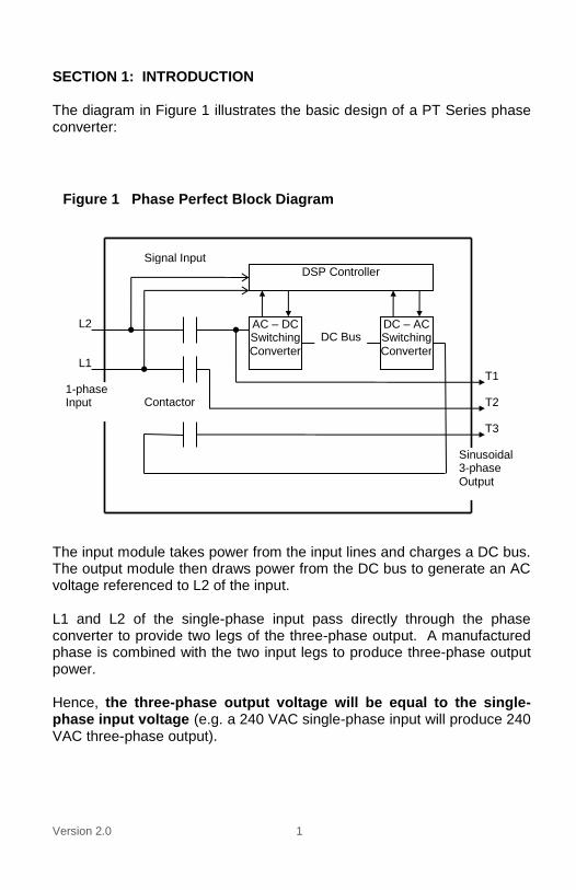
SECTION 1: INTRODUCTION The diagram in Figure 1 illustrates the basic design of a PT Series phase converter:
The input module takes power from the input lines and charges a DC bus. The output module then draws power from the DC bus to generate an AC voltage referenced to L2 of the input. L1 and L2 of the single-phase input pass directly through the phase converter to provide two legs of the three-phase output. A manufactured phase is combined with the two input legs to produce three-phase output power. Hence, the three-phase output voltage will be equal to the single-phase input voltage (e.g. a 240 VAC single-phase input will produce 240 VAC three-phase output).
AC – DC Switching Converter
DC – AC Switching Converter
DC Bus
DSP Controller
Contactor T2
T3
L1
L2
Signal Input
T1
Sinusoidal 3-phase Output
1-phase Input
Figure 1 Phase Perfect Block Diagram
Version 2.0 2
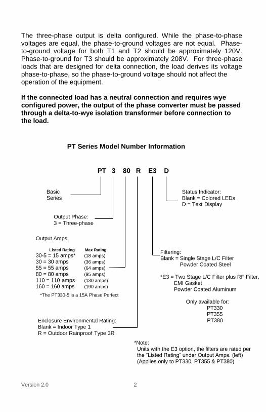
The three-phase output is delta configured. While the phase-to-phase voltages are equal, the phase-to-ground voltages are not equal. Phase-to-ground voltage for both T1 and T2 should be approximately 120V. Phase-to-ground for T3 should be approximately 208V. For three-phase loads that are designed for delta connection, the load derives its voltage phase-to-phase, so the phase-to-ground voltage should not affect the operation of the equipment. If the connected load has a neutral connection and requires wye configured power, the output of the phase converter must be passed through a delta-to-wye isolation transformer before connection to the load.
PT 3 80 R E3 D
Basic Series
Output Phase: 3 = Three-phase
Output Amps: Listed Rating Max Rating
30-5 = 15 amps* (18 amps) 30 = 30 amps (36 amps) 55 = 55 amps (64 amps) 80 = 80 amps (95 amps) 110 = 110 amps (130 amps) 160 = 160 amps (190 amps)
Enclosure Environmental Rating: Blank = Indoor Type 1 R = Outdoor Rainproof Type 3R
Status Indicator: Blank = Colored LEDs D = Text Display
PT Series Model Number Information
*The PT330-5 is a 15A Phase Perfect
*Note: Units with the E3 option, the filters are rated per the “Listed Rating” under Output Amps. (left) (Applies only to PT330, PT355 & PT380)
Filtering: Blank = Single Stage L/C Filter
Powder Coated Steel *E3 = Two Stage L/C Filter plus RF Filter,
EMI Gasket Powder Coated Aluminum Only available for: PT330 PT355
PT380

Version 2.0 3
SECTION 2: INSTALLATION Models are available in Type 1 indoor or Type 3R rain proof enclosures. These devices when configured in NEMA 1 enclosures are to be used in a heated, controlled indoor environment. The unit should be securely mounted to a solid, non-flammable vertical surface.
Mounting the Unit Properly locating the unit is important to the performance and normal operating life of the unit. The unit should be installed in a location free from:
Excessive dirt and dust
Corrosive gases or liquids
Excessive vibration
Airborne metallic particles It is important that the unit be located away from excessive dirt and dust. It should be securely fastened to a solid, non-flammable vertical surface using the mounting brackets provided with the unit. Make sure the mounting surface is capable of bearing the weight of the unit. Weights for each model can be found in the Specification Table of this document. Elevating the unit well above the ground will help to reduce the introduction of dust and contaminants into the enclosure. Larger models are provided with lifting eye bolts on the enclosure. CABLES, STRAPS OR CHAINS USED FOR LIFTING THESE UNITS MUST BE ATTACHED ONLY TO THE PROVIDED BRACKETS. In order to provide proper ventilation, do not obstruct the open space around the enclosure. In order to maintain air circulation for cooling, minimum clearance must be 2 inches on each side, and 6 inches top and bottom. Make sure air intake and exhaust openings are not obstructed. If the unit is mounted in a small room, cabinet or building, make certain there is adequate ventilation to provide cooling for the unit. Ambient Temperature Rating PT Series converters are intended for use in an ambient temperature no higher than 50°C.
Version 2.0 4
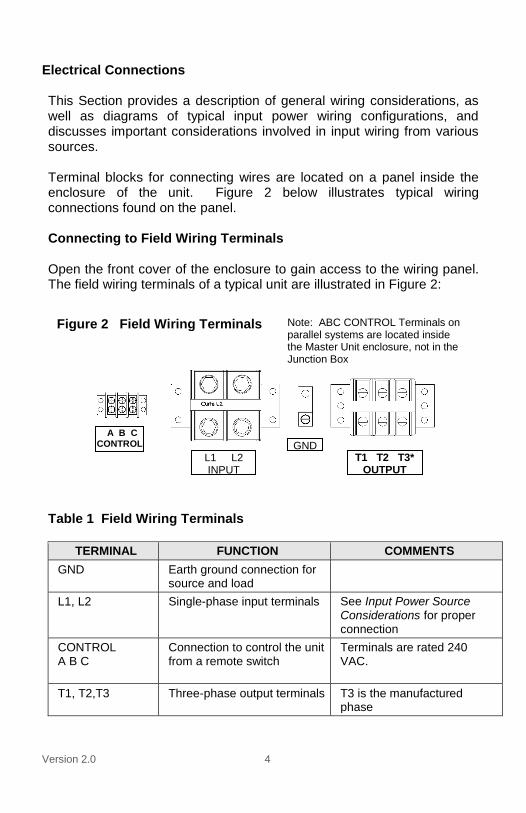
Electrical Connections This Section provides a description of general wiring considerations, as well as diagrams of typical input power wiring configurations, and discusses important considerations involved in input wiring from various sources. Terminal blocks for connecting wires are located on a panel inside the enclosure of the unit. Figure 2 below illustrates typical wiring connections found on the panel. Connecting to Field Wiring Terminals Open the front cover of the enclosure to gain access to the wiring panel. The field wiring terminals of a typical unit are illustrated in Figure 2:
Table 1 Field Wiring Terminals
TERMINAL FUNCTION COMMENTS
GND Earth ground connection for source and load
L1, L2 Single-phase input terminals See Input Power Source Considerations for proper connection
CONTROL A B C
Connection to control the unit from a remote switch
Terminals are rated 240 VAC.
T1, T2,T3 Three-phase output terminals T3 is the manufactured phase
Figure 2 Field Wiring Terminals
A B C CONTROL
L1 L2 INPUT
GND T1 T2 T3*
OUTPUT
Note: ABC CONTROL Terminals on parallel systems are located inside the Master Unit enclosure, not in the Junction Box

Version 2.0 5
GENERAL WIRING CONSIDERATIONS Installations must comply with all national and local electrical code requirements. General Wiring Considerations Include:
1. All models except PT3160 are suitable for use in a circuit capable of delivering not more than 5 kA RMS symmetrical amperes, 240V maximum.
2. Model PT3160 is suitable for use in a circuit capable of delivering not more than 10 kA RMS symmetrical amperes, 240 V maximum.
3. Use 600 V vinyl-sheathed wire or equivalent. The voltage drop of the leads needs to be considered in determining wire size. Voltage drop is dependent on wire length and gauge.
4. Wire used within the motor circuit and all field wiring terminals must be rated for at least 60 C.
5. Wires fastened to the terminal blocks shall be secured by tightening the terminal screws to a torque value listed in Table 2.
6. Use wire size suitable for Class 1 circuits.
7. For models with three-phase output, the input wire gauge must be sized to accommodate the single-phase input current, which will be approximately 1.8 times the total three-phase output current to the load(s). For example, if the output load is 20 HP, the three-phase output current will be approximately 54 amps, and the single-phase input current will be approximately 97 amps.
8. The maximum wire gauge for the input terminals is listed in Table 2.
9. Never allow bare wire to contact the metal surfaces.
10. Never connect AC main power to the output terminals; T1, T2, and T3.
11. Input power connections should be made by a qualified electrician into a 208V or 240V circuit with adequate current carrying capacity and the appropriate sized breaker.
Branch circuit protection to the phase converter should be provided by appropriate size fuses or a 2 pole, linked circuit breaker. Input circuit breaker and fuse ratings for each model are listed in Table 3.

Version 2.0 6
Table 2 Field Wiring Terminal Specifications
Model PT330-5 PT330 PT355 PT380*
Input Terminals
Tightening Torque
16 in.-lb. 16 in.-lb. 120 in.-lb. (2/0-6 AWG) 40 in.-lb. (8 AWG) 35 in.-lb. (10-14 AWG)
275 in.-lb.
Wire Size 18 - 4 AWG 18 - 4 AWG 14 - 2/0 AWG 6 AWG - 250 MCM
Output Terminals
Tightening Torque
16 in.-lb. 16 in.-lb. 16 in.-lb. 50 in.-lb. (2 AWG)
45 in.-lb. (4-8 AWG) 35 in.-lb. (10-14 AWG)
Wire size 18 - 4 AWG 18 - 4 AWG 18 – 4 AWG 14 - 2 AWG*
*Technical Bulletin: PT380 Wire Size – See Next Page
Model PT3110 PT3160
Input Terminals
Source Line Side PT Unit Side Source Line Side PT Unit Side
Tightening Torque
275 in. lbs 275 in. lbs 375 in. lbs 192 in. lbs
Wire Size 350kcmil – 6 AWG 350kcmil – 6 AWG 500kcmil –
4 AWG 3/8 –
16 Stud
Output Terminals
Load Side PT Unit Side Load Side PT Unit Side
Tightening Torque
120 in. lbs (2/0-6 AWG) 40 in. lbs (8AWG) 35 in. lbs (10-14 AWG)
120 in. lbs (2/0-6 AWG) 40 in. lbs (8AWG) 35 in. lbs (10-14 AWG)
375 in. lbs 61 in. lbs
Wire Size 2/0 – 14 AWG 2/0 – 14 AWG 500kcmil –
4 AWG ¼ - 20 Stud

Version 2.0 7
Technical Bulletin: 01/01/2018
Phase Perfect PT380 – Output Terminal Block & Wire Size
The recommended wire size on the output terminal block is currently listed as
14-2 AWG. Previously, the max output current of the PT380 was listed at 96A.
As of 01/01/2018, the max output current of the PT380 has been updated:
PT380 Max Output Current: 95A
To ensure that all installations are compliant with local electrical codes and with
the PT380 installation requirements, the maximum output current should be rated
at 95A. A 60°C, 2 AWG wire is compliant at 95 amps.
Version 2.0 8
Field Wiring for Parallel Units
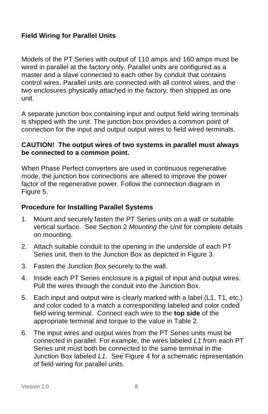
Models of the PT Series with output of 110 amps and 160 amps must be wired in parallel at the factory only. Parallel units are configured as a master and a slave connected to each other by conduit that contains control wires. Parallel units are connected with all control wires, and the two enclosures physically attached in the factory, then shipped as one unit. A separate junction box containing input and output field wiring terminals is shipped with the unit. The junction box provides a common point of connection for the input and output output wires to field wired terminals. CAUTION! The output wires of two systems in parallel must always be connected to a common point. When Phase Perfect converters are used in continuous regenerative mode, the junction box connections are altered to improve the power factor of the regenerative power. Follow the connection diagram in Figure 5. Procedure for Installing Parallel Systems
1. Mount and securely fasten the PT Series units on a wall or suitable vertical surface. See Section 2 Mounting the Unit for complete details on mounting.
2. Attach suitable conduit to the opening in the underside of each PT Series unit, then to the Junction Box as depicted in Figure 3.
3. Fasten the Junction Box securely to the wall.
4. Inside each PT Series enclosure is a pigtail of input and output wires. Pull the wires through the conduit into the Junction Box.
5. Each input and output wire is clearly marked with a label (L1, T1, etc.) and color coded to a match a corresponding labeled and color coded field wiring terminal. Connect each wire to the top side of the appropriate terminal and torque to the value in Table 2.
6. The input wires and output wires from the PT Series units must be connected in parallel. For example, the wires labeled L1 from each PT Series unit must both be connected to the same terminal in the Junction Box labeled L1. See Figure 4 for a schematic representation of field wiring for parallel units.

Version 2.0 9
CAUTION! Never connect unlike wires from the PT Series units to the same terminal in the Junction Box.
Otherwise, the units may be severely damaged, and the warranty will be void.
7. Pull source input wires and output wires to the load through conduit into the Junction Box and connect to the bottom side of the appropriate field wiring terminals. Torque to values in Table 2.
Junction box with field wiring terminals
Figure 3 Parallel Systems
Master Unit Slave Unit

Version 2.0 10
Control Lines
PT Series Master Unit PT Series Slave Unit
Junction Box
L1 L2 T1 T3
Field wiring terminations are made on terminal blocks in the Junction Box
Line in from source
Line out to load
Figure 4 PT SERIES PARALLEL FIELD WIRING DIAGRAM
L1 L2 T1 T2 T3 OUTPUT INPUT
L1 L2 T1 T3

Version 2.0 11
WARNING! Converters used in continuous regenerative applications must configure from the factory for this use. Do not use this wiring configuration in a standard converter.
Control Lines
PT Series Master Unit PT Series Slave Unit
Junction Box
L1 L2 T2 T3
Field wiring terminations are made on terminal blocks in the Junction Box
Line in from source
Line out to load
Figure 5 PT SERIES PARALLEL FIELD WIRING DIAGRAM FOR
CONVERTERS IN CONTINUOUS REGENERATIVE MODE
L1 L2 T1 T2 T3 OUTPUT INPUT
L1 L2 T2 T3

Version 2.0 12
Table 3 Input Circuit Breaker and Fuse Ratings
Model PT330-5 PT330 PT355 PT380 PT3110 PT3160
Maximum fuse rating, Class RK5
35 70 125 200 250 400
Maximum fuse rating, Class 200
35 70 125 200 250 400
Maximum circuit breaker rating, amps
35 70 125 200 250 400
Input Power Source Considerations The unit
can be operated from most input power sources ranging from
187 VAC to 260 VAC. However, specific input wiring issues must be considered when wiring to three-phase input sources.
WARNING! Incorrect L1 and L2 wiring from some three-phase sources can result in high phase-to-ground voltage. These considerations are outlined in: Figure 6 Power Source Configurations:

Version 2.0 13
PT Series Phase
Converter
120 V
120 V
240 V
L1
L2
GND
Single-Phase 240V/120V Source
WARNING! Three-phase, 208Y/120V Single-phase 208V input power can be taken from two legs of a three-phase grounded-wye source. There are two possible ways to connect L1 and L2 to the unit from any two legs. If the unit is connected incorrectly, the voltage from output line T3 to ground will be over 240V. Reversing L1 and L2 on the input should lower the T3 to ground voltage to 120V.
Single-phase, 120V/240V, 3 Wire In most installations, single-phase 240V input power will be taken from a 240V/120V center tap source. Connect L1 and L2 to the input terminals.
PT Series Phase
Converter
240 V
120
V
120
V
208
V
1
2 3
L1
L2
GND
Three-Phase 240V Delta Source
PT Series Phase
Converter
120 V
120 V
120 V 208
V
GND
L1
L2
Three-Phase 208Y120V Source
WARNING! Three-phase, 240V/120V, Delta In some situations, single-phase 240V input power may be derived from a three-phase source as illustrated to the left. Caution must be exercised if using such a source for power input to the unit. Power should only be derived from legs 1 & 2, with a center ground, as illustrated. Power derived from legs 2 & 3, or 3 & 1, may result in output phase-to-ground voltage well above 200V. To avoid potentially hazardous voltage, always verify the phase-to-ground voltage for the L1 and L2 inputs is approximately 120V.
Figure 6 Power Source Configurations

Version 2.0 14
Section 3: TYPICAL SYSTEM CONFIGURATIONS A PT Series phase converter
is designed to simplify installation, to provide
maximum versatility, and to eliminate or minimize the need for external electrical components and related costs. The output voltage of the unit
is sinusoidal with very little harmonic
content, eliminating the need for output filtering that would often be required for a variable frequency drive (VFD). With little distortion of the input current, the unit does not require input filtering to comply with IEE519, the standard that sets limits for distortion of utility mains power. All types of equipment, including inductive, resistive, and capacitive loads can be safely powered by a PT Series Phase Perfect. Typical
installations are diagrammed and explained below:
A power supply configuration for use in powering multiple loads
A configuration in which a remote switch turns the unit ON/OFF Power Supply Configuration The unit can be configured as a power supply to provide power to multiple loads of any type, including inductive, resistive, and capacitive loads. CAUTION! The wire connecting A to C at the top of the Control Terminal strip is NOT a jumper, and should NOT be removed. Separate, properly sized breakers should be provided for each motor load to be powered. The power supply configuration used to power multiple motor loads or loads with integrated controls is illustrated in Figure 7:

Version 2.0 15
Input Disconnect
Switch
Motor Load
3-phase load center with
branch circuit protection for
each load
Each load must have independent over-current protection and controls
Figure 7 Power Supply Configuration
PT Series
Phase Converter
Load with integrated controls
Single-phase
panel or
power source
Motor Starter Panel

Version 2.0 16
Follow this procedure when wiring the unit as a power supply to provide
three-phase power to multiple loads or to loads with integrated controls:
1. Verify that no input power is connected to the unit by turning the input
disconnect to OFF, then lock and tag it.
2. Open the front cover to gain access to the wiring terminals. See the Section
2, Connecting to Field Wiring Terminals, for a drawing illustrating the wiring
terminals.
3. Connect input power to the unit from an appropriate single-phase circuit. See
the Section 2, Input Power Source Considerations, for additional information.
4. Before energizing the input power, measure the source voltage. Phase-to-
phase voltage must be within the input range of 187-260VAC, and the phase-
to-ground voltage should be half this value. For installations with one 240V
power wire and a neutral, the 240V wire must be installed on L1.
5. Energize the unit before any loads are connected to the output and measure
the output phase-to-phase voltages to ensure they are within the specified
range. Because the three-phase output is delta-configured three-phase, the
output phase-to-ground voltages will not be equal. T3-to-ground voltage will
be higher than T1 or T2 to ground.
6. Turn the unit OFF by means of the input disconnect, lock and tag it, then wait
at least 30 minutes for any internal charges to dissipate.
7. Connect the output wires to the output terminals. Torque the terminal screws
to the values listed in Table 2 Field Wiring Terminal Specifications.
8. Close and latch front cover.
9. Turn the unit ON from the disconnect switch. Power will be available to the
load circuits after an approximately five to eight second delay. Check any
three-phase motor loads for correct rotation. If the motor rotation is incorrect,
reverse any two of the three output power leads to that motor.
10. A low power remote switch may be wired into the Control Terminal of the unit
to provide remote ON/OFF switching of the unit.

Version 2.0 17
WARNING! When the converter is turned OFF using a remote switch on the Control Terminals, dangerous voltage is still present on the input lines, inside the enclosure and on certain output lines to ground. Never open the enclosure or perform maintenance on the unit and its connected loads when the input disconnect switch is in the ON position. Remote ON/OFF Control
WARNING! When the converter is turned OFF using a remote switch on the Control Terminals, dangerous voltage is still present on the input lines, inside the enclosure and on certain output lines to ground. Never open the enclosure or perform maintenance on the unit and its connected loads when the input disconnect switch in the ON position. When a low power remote switch is connected to the Control Terminals, the unit and any connected loads can be switched ON/OFF by a remote switch. The remote switch must be rated at a minimum of 240 VAC, 0.5 amp. A PT Series power used to power a motor load with remote ON/OFF is illustrated in Figure 8:
Input Power Source
Input Disconnect
Switch
PT Series Phase
Converter
Motor Load
Remote switch rated 240V, 0.5A. Closed switch will energize the unit and start the load after a 5-8 second delay. Make sure switch leads are connected to A & B on the Control Terminals.
Figure 8 Power Supply with Remote ON/OFF

Version 2.0 18
Follow this procedure when wiring a remote switch to control the unit:
1. Verify that no input power is connected to the unit by turning the input
disconnect to OFF, then lock and tag it. 2. Open the front cover to gain access to the wiring terminals. See the Section
2, Connecting to Field Wiring Terminals, for a drawing illustrating the wiring
terminals. CAUTION! The wire connecting A to C at the top of the Control Terminal is NOT a jumper, and should NOT be removed.
3. Verify that control terminals A and B are shorted together by a metal jumper.
The unit is shipped from the factory in this configuration.
4. Remove the metal jumper and connect the remote switch leads to Control Terminals A and B. When operating, closing the remote switch will energize the unit and start the load after approximately a five to eight second delay. The control circuit should be rated for 240V, 0.5A. A 3A fuse labeled F501 protects the remote switch circuit.
Section 4: OPERATION Operation of a PT Series phase converter is simple and straightforward after completion of installation and wiring. ON/OFF Options There are two ways to turn a PT Series phase converter ON and OFF: ON/OFF With Input Power Disconnect Switch In most cases, the unit should be installed with a disconnect switch on the line side of the unit. When in the OFF position, this disconnect switch will break the connection between the unit and the input power source.
WARNING! Make sure the input power disconnect switch is in the OFF position before opening the front cover to the unit. Opening the front cover with the switch in the ON position exposes the user to the risk of electric shock. When the unit is energized, output power is provided to the load after a delay of approximately five to eight seconds. ON/OFF With a Low Power Remote Switch When Phase Perfect is configured with a remote ON/OFF switch on the Control Terminals, the input power disconnect switch is left in the ON

Version 2.0 19
position. When the remote switch connected to the Control Terminals is closed, the unit energizes, and output power is provided to the load after a delay of approximately five to eight seconds. When the input power is ON, and the remote control switch is open, the unit is not energized and will not consume any power. No phase-to-phase voltage will be present on the output lines.
WARNING! When the converter is turned OFF using a remote switch on the Control Terminals, dangerous voltage is still present on the input lines, inside the enclosure and on certain output lines to ground. Never open the enclosure or perform maintenance on the unit and its connected loads when the input disconnect switch in the ON position. When either the input power disconnect switch is OFF, or the remote switch on the Control Terminals is open, the status LEDs will be off. If the unit is equipped with the optional text display, the status screen will be blank. Status Indicators The GREEN, YELLOW, and RED status LEDs are found on the control printed circuit board inside the enclosure, or are mounted on the front cover when the unit is equipped with optional EMI enclosure. The status lights provide information about the operating status of the unit, and provide useful troubleshooting information. An optional text display status screen is also available on some models that provides 2 row, 32 character text messages for status indicators. Three basic status LED indications are:
STEADY GREEN status LED
STEADY YELLOW status LED
FLASHING RED status LED
Note: The red and yellow status lights may flash briefly when starting heavy loads. This is normal and can be ignored.
Different combinations of the status LEDs provide information about the operating status of the unit, and can be used in troubleshooting. A complete listing of status indicators is provided in the Section 6 Status Indicators and Troubleshooting.

Version 2.0 20
Section 5: STATUS INDICATORS AND TROUBLESHOOTING This section provides troubleshooting information for potential system problems.
WARNING! In some instances, such as overheating, the unit will shut down, then automatically restart when conditions allow.
Always disconnect input power from the unit and wait for internal electrical charges to dissipate before performing service on the unit or its connected loads.
General Troubleshooting Tips After the system is properly connected to input power, turn the unit ON with the disconnect switch and/or input circuit breaker. It is always advisable to check the operating status of the converter before connecting any loads to the output. If the unit fails to energize, and all status indicators are off, check the following: 1. Verify that the appropriate circuit breaker in the electrical source
distribution panel is set ON and is properly sized. 2. Check the control circuit
fuse, labeled F501, located on the panel
inside the unit enclosure. If necessary, replace with appropriate 3A fuse.
3. Verify that the metal jumper on the Control Terminal is connected either A to B for power supply configuration. The unit will not operate unless the metal jumper or control circuit wires are connected to the appropriate control terminals. CAUTION! The wire connecting A to C at the top of the Control Terminal is NOT a jumper, and should NOT be removed.
Refer to the following Status Indicator Table for additional troubleshooting tips.

Version 2.0 21
Status Indicators The status lights and the optional text status screen provide are useful for detecting and diagnosing system problems. The Status Indicator Tables provide a list of status indicators, followed by a description and potential causes of the problem. The GREEN, YELLOW, and RED status LEDs are found on the control printed circuit board inside the enclosure, or are mounted on the front cover when the unit is equipped with optional EMI enclosure. The status lights provide information about the operating status of the unit, and provide useful troubleshooting information. An optional text display status screen mounted in the door of the enclosure is also available on some models that provide 2 row, 32 character text messages for status indicators. See Table 4

Version 2.0 22
Table 4 Status Indicators
LED INDICATOR TEXT INDICATOR COMMENTS AND TROUBLESHOOTING TIPS NOTES
STEADY GREEN SYSTEM ON NORMAL
FLASHING GREEN STARTING
STEADY YELLOW
STOPPED OVERTEMP WAIT FOR RESTART
Check for faulty fan, or ventilation opening obstructions. Reduce ambient temperature.
2
FLASHING GREEN STEADY YELLOW
DEFECTIVE TEMP SENSOR
Failed temp sensor (TM circuit board) or loose connection to TM circuit board
3
STEADY RED C1 VOLTAGE LOW Check charging circuit fuse (F701), relay and diode. Possible failed bus capacitor on VPOS
2
STEADY GREEN STEADY YELLOW
C2 VOLTAGE LOW Check charging circuit fuse (F701), relay and diode. Possible failed bus capacitor on VNEG
2
FLASHING YELLOW FLASHING RED
C1 OVER VOLTAGE Possible heavy power regeneration from load. Possible voltage sensing problem on EA200 circuit board
3
FLASHING YELLOW C2 OVER VOLTAGE Possible heavy power regeneration from load. Possible voltage sensing problem on EA200 circuit board
3
STEADY GREEN FLASHING RED
POSSIBLE SHORT C1
Internal fault possible, contact factory 3
FLASHING GREEN STEADY RED
POSSIBLE SHORT C2
Internal fault possible, contact factory 3
FLASHING RED IGBT FAULT INPUT MODULE
Possible failed IGBT or driver circuit board on input module
3
FLASHING GREEN FLASHING RED
IGBT FAULT OUTPUT MODULE
Possible failed IGBT or driver circuit board on output module
3
STEADY YELLOW STEADY RED
INPUT FREQUENCY OUT OF RANGE
Input frequency must be 46-64 Hz. Generator source must be stable. Possible voltage distortion in source power.
2
STEADY YELLOW FLASHING RED
LOW INPUT V AUTO RESTART
Increase input voltage to specified input range if possible. See Note 1 below.
1
FLASHING YELLOW STEADY RED
LOW INPUT V AUTO RESTART 1HR
Increase input voltage to specified input range if possible. See Note 1 below.
1
STEADY GREEN STEADY RED
LOW INPUT V AUTO RESTART 10S
Increase input voltage to specified input range if possible. See Note 1 below.
1
STEADY GREEN STEADY YELLOW STEADY RED
HIGH INPUT V AUTO RESTART
Decrease input voltage to specified input range if possible. See Note 1 below.
1
STEADY GREEN STEADY YELLOW FLASHING RED
HIGH INPUT V AUTO RESTART 1HR
Decrease input voltage to specified input range if possible. See Note 1 below.
1
Version 2.0 23
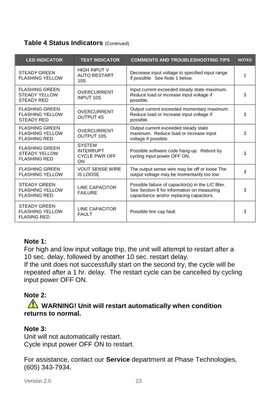
Table 4 Status Indicators (Continued)
LED INDICATOR TEXT INDICATOR COMMENTS AND TROUBLESHOOTING TIPS NOTES
STEADY GREEN FLASHING YELLOW
HIGH INPUT V AUTO RESTART 10S
Decrease input voltage to specified input range if possible. See Note 1 below.
1
FLASHING GREEN STEADY YELLOW STEADY RED
OVERCURRENT INPUT 10S
Input current exceeded steady state maximum. Reduce load or increase input voltage if possible.
3
FLASHING GREEN FLASHING YELLOW STEADY RED
OVERCURRENT OUTPUT 4S
Output current exceeded momentary maximum. Reduce load or increase input voltage if possible.
3
FLASHING GREEN FLASHING YELLOW FLASHING RED
OVERCURRENT OUTPUT 10S
Output current exceeded steady state maximum. Reduce load or increase input voltage if possible.
3
FLASHING GREEN STEADY YELLOW FLASHING RED
SYSTEM INTERRUPT CYCLE PWR OFF ON
Possible software code hang-up. Reboot by cycling input power OFF ON.
3
FLASHING GREEN FLASHING YELLOW
VOUT SENSE WIRE IS LOOSE
The output sense wire may be off or loose The output voltage may be momentarily too low
3
STEADY GREEN FLASHING YELLOW FLASHING RED
LINE CAPACITOR FAILURE
Possible failure of capacitor(s) in the L/C filter. See Section 8 for information on measuring capacitance and/or replacing capacitors.
3
STEADY GREEN FLASHING YELLOW FLASING RED
LINE CAPACITOR FAULT
Possible line cap fault 3
Note 1: For high and low input voltage trip, the unit will attempt to restart after a 10 sec. delay, followed by another 10 sec. restart delay. If the unit does not successfully start on the second try, the cycle will be repeated after a 1 hr. delay. The restart cycle can be cancelled by cycling input power OFF ON. Note 2:
WARNING! Unit will restart automatically when condition returns to normal. Note 3: Unit will not automatically restart. Cycle input power OFF ON to restart. For assistance, contact our Service department at Phase Technologies, (605) 343-7934.

Version 2.0 24
Section 6: FEATURES AND SPECIFICATIONS Important Features of the Phase Perfect
®
Clean, balanced power under all load
conditions for even the most
demanding applications
Electronic power factor correction on
the input module for efficient, utility-
friendly operation
IEEE 519 compliant
Sinusoidal output voltage allows
operation of all types of sensitive
equipment
Protects operated equipment from
over-voltage, under-voltage and other
adverse events
97% efficiency typical
Simple to configure and install
Remote ON/OFF switching capability
standard on all models
EMI filter options available to reduce
both conducted and emitted noise
Optional plasma display for 2 line, 32
character text display of status
indicators and troubleshooting codes
New compact design in wall mounted
enclosures
Outdoor rainproof enclosures available
Clean power fed back to power grid
under regenerative load conditions
Single-Phase to
Three-Phase Conversion

Version 2.0 25
Table 5 Specifications
MODEL PT330-5 PT330 PT355 PT380 PT3110 PT3160
Input
1-phase, AC 187-260V 50/60 Hz
1-phase, AC 187-260V 50/60 Hz
1-phase, AC 187-260V 50/60 Hz
1-phase, AC 187-260V 50/60 Hz
1-phase, AC 187-260V 50/60 Hz
1-phase, AC 187-260V 50/60 Hz
27A listed 33A max
54A listed 65A max
98A listed 115A max
143A listed 171A max
196A listed 234A max
285A listed 342A max
Output
3-phase, AC 187-260V 50/60 Hz
3-phase, AC 187-260V 50/60 Hz
3-phase, AC 187-260V 50/60 Hz
3-phase, AC 187-260V 50/60 Hz
3-phase, AC 187-260V 50/60 Hz
3-phase, AC 187-260V 50/60 Hz
15A listed 18A max
30A listed 36A max
55A listed 64A max
80A listed 95A max
110A listed 130A max
160A listed 190A max
Rated output (240V)
6.2 KVA listed
7.5 KVA max
12.5 KVA listed
14.9 KVA max
22.9 KVA listed
26.6 KVA max
33.2 KVA listed
39.4 KVA max
45.7 KVA listed
53.9 KVA max
66.4 KVA listed
78.9 KVA max
General Specifications:
Enclosure: Type 1 indoor or Type 3R rain proof, wall mount, powder coated steel or powder coated aluminum
Ambient temperature operating range: -10C to +50C
Storage temperature range: -20C to +60C
Typical efficiency at full load: 97% Table 6 Fuses
FUSE ID FUSE RATING COMMENTS
F1 2 A, slow blow Located on PCB PWR602
F2 5 A, slow blow Located on PCB PWR602
F3 5 A, fast blow Located on PCB PWR602
F501 3 A, fast blow Panel mounted, protects CONTROL circuit
F701 12 A, slow blow Panel mounted, protects DC bus charging circuit

Version 2.0 26
Section 7: ROUTINE MAINTENANCE Regular maintenance should be performed on your Phase Perfect converter to ensure safe and efficient operation. This maintenance should be performed at least annually or more frequently for converters operating under extreme conditions such as heavy continuous loads, high temperature environments and dusty, dirty conditions. Heat Sinks and Cooling Fans Remove the top cover and visually inspect the heat sinks and other components that are subjected to air circulated by the cooling fans. Use compressed air to remove any accumulated dirt and debris. Make sure the cooling fans are operating, are clean and turn freely. Visual Inspection Inspect wires and components for discoloration due to overheating or arcing and/or deformation. Torque the terminals on the power connection to values in Table 2 Field Wiring Terminal Specifications. Line Filter Capacitors
CAUTION: Line filter capacitors should be inspected annually at a minimum. If the equipment is frequently operated under heavy load, inspection every six months is recommended. Important: Do not operate the Phase Perfect
® with degraded line
filter capacitors. Replacement of the capacitors every three years is recommended. These capacitors suppress electrical noise caused by the switching of the IGBTs. If they are degraded the electrical noise can damage equipment connected to the converter. Line filter capacitors should be visually inspected and electrically tested on a routine basis. The capacitors can be observed by opening the front cover of the converter. See Figure 10 below to identify the line filter capacitors.

Version 2.0 27
Table 7 Nominal Filter Capacitor Values in MicroFarads (uF)
Converter Model Number of Capacitors Capacitance (uF)
PT330-5 2 40 uF
PT330 2 40 uF
PT355 4 40 uF
PT380 4 60 uF
PT3110 8 40 uF
PT3160 8 60 uF

Version 2.0 28
Figure 10 Line Filter Capacitors*
PT330 Capacitors
See Notes Below

Version 2.0 29
Figure 10 Line Filter Capacitors (continued)
All Other PT Model Capacitors

Version 2.0 30
Line Filter Capacitors
Visually inspect the line filter capacitors and the wires connected to them for any discoloration and for bulges in the canister. Using a multi-meter set to measure capacitance; check the capacitance of each capacitor by measuring between the two terminals on the capacitor. Remove the wire from at least one terminal of the capacitor in order to obtain an accurate measurement. Compare to the capacitor value in Table 7. If any capacitor value is less than specified by more than 15% contact Phase Technologies service department to order replacement capacitors. Phase Technologies 605-343-7934 www.phasetechnologies.com If you do not have a meter or other means to test the capacitors it is recommended to replace the capacitors every three years as a preventive measure.
PHASE TECHNOLOGIES, LLC
231 East Main Street North Rapid City, SD 57701
605-343-7934 – Main
866-250-7934 – Toll Free 605-343-7943 – Fax
www.phasetechnologies.com

Version 2.0 31
Notes

PO W ER B Y D ES I GN
w w w . p h a s e t e c h n o l o g i e s . c o m