Power Anomaly Effects and Costs in Low-Voltage Mobile ...
14
University of South Carolina Scholar Commons Faculty Publications Electrical Engineering, Department of 4-1-2006 Power Anomaly Effects and Costs in Low-Voltage Mobile Power Systems Shengyi Liu Boeing, [email protected] Charles H. Singer NAVAIR Roger A. Dougal University of South Carolina - Columbia, [email protected] Follow this and additional works at: hps://scholarcommons.sc.edu/elct_facpub Part of the Electrical and Computer Engineering Commons is Article is brought to you by the Electrical Engineering, Department of at Scholar Commons. It has been accepted for inclusion in Faculty Publications by an authorized administrator of Scholar Commons. For more information, please contact [email protected]. Publication Info Published in IEEE Transactions on Aerospace and Electronic Systems, Volume 42, 2006, pages 612-624. hp://ieeexplore.ieee.org/xpl/RecentIssue.jsp?punumber=7 © 2006 by IEEE
Transcript of Power Anomaly Effects and Costs in Low-Voltage Mobile ...

University of South CarolinaScholar Commons
Faculty Publications Electrical Engineering, Department of
4-1-2006
Power Anomaly Effects and Costs in Low-VoltageMobile Power SystemsShengyi LiuBoeing, [email protected]
Charles H. SingerNAVAIR
Roger A. DougalUniversity of South Carolina - Columbia, [email protected]
Follow this and additional works at: https://scholarcommons.sc.edu/elct_facpub
Part of the Electrical and Computer Engineering Commons
This Article is brought to you by the Electrical Engineering, Department of at Scholar Commons. It has been accepted for inclusion in FacultyPublications by an authorized administrator of Scholar Commons. For more information, please contact [email protected].
Publication InfoPublished in IEEE Transactions on Aerospace and Electronic Systems, Volume 42, 2006, pages 612-624.http://ieeexplore.ieee.org/xpl/RecentIssue.jsp?punumber=7© 2006 by IEEE

Power Anomaly Effects andCosts in Low-Voltage MobilePower Systems
SHENGYI LIU, Senior Member, IEEEUniversity of South Carolina
CHARLES H. SINGERNAVAIR
ROGER A. DOUGAL, Senior Member, IEEEUniversity of South Carolina
Electric power anomalies or disturbances can disrupt the
normal operation of equipment, accelerate aging, or even
cause outright failures thus resulting in increased costs of
maintenance and reduced system reliability. Past research on
the effects caused by power anomalies has been mostly focused
on industrial, commercial, or residential systems, or on power
distribution equipment. A literature survey reveals that there
is no comprehensive review related to low-voltage (LV) power
systems and utilization equipment applicable to military combat
vehicles, such as aircraft and ships. This paper summarizes the
results of a new literature survey that focused on the causes,
effects, and mitigation methods for power anomalies typical of LV
mobile power systems. Electric power anomaly cost data collected
from the literature are also presented, from which the costs of
anomalies to the national defense are estimated using some simple
rationales.
Manuscript received February 22, 2005; revised September 2, 2005;released for publication October 6, 2005.
IEEE Log No. T-AES/42/2/876438.
Refereeing of this contribution was handled by W. M. Polivka.
This work was supported by the U.S. Naval Air Systems Commandunder Contract N00421-00-D-0154.
Authors’ addresses: S. Liu and R. A. Dougal, Dept. of ElectricalEngineering, University of South Carolina, Columbia, SC 29208,E-mail: ([email protected]); C. H. Singer, Electric Power SystemDivision, AIR-4.4.4.1, NAVAIR, 48298 Shaw Rd., Patuxent River,MD 20670-1900.
0018-9251/06/$17.00 c° 2006 IEEE
I. INTRODUCTION
Power anomalies or power disturbances (PDs),whether resulting from natural causes or humanerrors, from unpredicted incidents or scheduledevents, are detrimental to both power distribution andutilization equipment. Depending upon the criticalityof the equipment, the consequences can be very costlyor even catastrophic. One report [1] shows that poweroutages and interruptions cost the U.S. economybetween $104 billion and $164 billion a year due toequipment damage, materials loss, idled labor, and lostproduction or sales, and another $15 billion to $24billion a year is lost due to power quality phenomena.The total loss amounts to 1.2% to 1.9% of the U.S.gross domestic product (GDP) (in 2001, the U.S. GDPwas $10,100.8 billion in 2001 dollars [2]). To estimatethe costs of power interruptions and disturbances tothe national defense industry and services (includingmilitary installations, war machines, weapons andspace programs, etc.), one simple rationale wouldbe to compare the military spending with the GDP.According to CDI [3], the U.S. total military andmilitary-related spending in 2001 was $484.3 billion.This yields a loss to the national defense of $5.8 to$9.2 billion a year just due to electric PD problems.To improve the estimate, the characteristics of militaryequipment and power systems must be considered.In general, the PD cost is a function of severalsystem and equipment parameters: the frequencyof occurrence of disturbances, the sensitivity of theequipment to disturbances, the expenses of equipmentmanufacturing and maintenance, and finally, thecosts of other consequences due to disturbances. Themilitary equipment is often designed to be robustand thus less sensitive to disturbances. Therefore,the probability of a disturbance event to becomedisruptive or to cause damaging effect is lowerin military equipment. On the other hand, unlikeindustrial and commercial stationary systems, mobilemilitary systems are subject to disturbances morefrequently due to their own operating characteristics,and furthermore, they are often required to workunder extreme conditions. In addition, the militaryequipment is of higher values, and the maintenanceis more costly, thus the average cost per disturbanceis probably higher than that in the industrial andcommercial equipment. However, the data for theseparameters are currently not available. Clearly, morestudies are needed to improve the estimate.In military applications, the PD problem is
not only an issue of economy, but also an issueof availability. In wartimes, the consequencesof a malfunctioning or failed radar system forearly-warning of hostile objects can be disastrous,including the loss of lives, or whole battles. It is clearthat the cost category in this case extends far beyondthe expenses of equipment, labor, and disruptedoperations.
612 IEEE TRANSACTIONS ON AEROSPACE AND ELECTRONIC SYSTEMS VOL. 42, NO. 2 APRIL 2006

Given the significance of the PD effects andcosts, the authors of this paper conducted a literaturesurvey to collect data particularly focusing on thedisturbances in low-voltage (LV) power systemsapplicable to military combat vehicles such as aircraftsand ships. Because the electric power is used tooperate computers, control and communicationsystems (the brains of these war machines) the PDeffect is critically important. For all-electric vehiclesof the future, it is obvious that the electric powerreliability will be critical to the vehicles’ survival inbattlefields.In reviewing the collected literature, we noticed
that there have been tremendous research effortson PD effects. However, the majority of theprevious work focused on applications for industrial,commercial, residential, and PD equipment. Inparticular, there is no comprehensive review relatedto LV power systems and utilization equipmentapplicable to military combat vehicles, such asaircraft and ships. The purpose of this paper is tosummarize and review the PD effects and cost datagathered from the literature that are typical of LVpower systems, thereby estimating the PD costs tomilitary installed electric power systems used inair-, sea- and land-based vehicles. These results areuseful for reliability and economic analysis in designand development of PD mitigation methods andtechnologies.The nomenclature of disturbance types used in this
paper follows the IEEE standard classification [4].We discuss the disturbances including 1) transients,2) short- and long-duration voltage variations, 3)waveform distortion, 4) voltage imbalance, 5) powerfrequency variations, and 6) static charge. Broadbandnoise and electromagnetic interference (EMI) arenot discussed here. Whenever possible, the cause,effect, cost, and mitigation method of each type ofdisturbance is presented based on the literature survey.
II. CHARACTERISTICS OF LV MOBILE POWERSYSTEMS
Currently, the electric power systems incombat vehicles primarily power dc electronicssuch as computers, displays, sensors, control andcommunication systems; ac equipment such asprotection relays, bus ties, valves, actuators, andequipment for lighting, heating, and cooling; and highvoltage dc equipment such as surveillance radar, etc.In all-electric combat vehicles of the future, electricpower will also be used for propulsion.The characteristics of electric power systems for
military vehicles differ significantly from one toanother depending upon scopes and scenarios. We usean aircraft electric power system here as a baselinefor our analysis. A typical aircraft LV electric powersystem is shown in Fig. 1. In this system, the prime
mover is the aircraft engine. The main bus from thegenerator is 3Á, 400 Hz, 115 Vac (line-to-ground).The auxiliary power unit (APU) provides the startingpower to the engine, and the emergency power tothe system in case of a failure of the engine or thegenerator. The onboard battery unit can providelimited power to operate the most critical equipmentif the aircraft suffers a loss of ac power. On theload side, power is available for the following loadtypes: 1) 115 Vac, 400 Hz, 2) 115 Vac, 60 Hz,3) 26 Vac, 400 Hz, 4) 28 Vdc, and 5) 270 Vdc. Theaircraft structure serves as the neutral conductor of the3-phase power system, the return conductor for the dcloads, and the safety and reference “ground.”In terms of characteristics of operation and
power anomalies, several features distinguish aircraftelectric power systems from terrestrial utility systems.First, the system start, stop, and voltage transfer,which cause disturbances, are normal operations inaircraft systems, whereas utilities generate powercontinuously unless a power failure or a scheduledinterruption occurs. Secondly, aircraft power systemsare autonomous and compact, therefore the effect ofdisturbances between source and source, source andload, and load and load are more pronounced. Thirdly,aircraft uses a 400 Hz ac main with multiple 400 Hz115 Vac, 60 Hz 115 Vac, 400 Hz 26 Vac, 28 Vdc,and 270 Vdc distribution panels or branches; whereasterrestrial systems use 50/60 Hz in all transmission,distribution, and branch circuits. Fourthly, frequencyvariation becomes an issue in aircraft systems becauseof small capacities (»kVA) of generators relativeto the loads. The issue generally does not exist interrestrial systems because of the stiffness of thegrid, except the backup systems in hospitals anddata centers, where small capacity generators arealso used. Finally, there are no present terrestrialrequirements for distributing dc voltage, whereasaircraft utilizes 28 and 270 Vdc for various systems.Thus dc anomalies must be specifically addressed.Table I lists the comparison of terrestrial and aircraftLV electrical system anomalies, which shows thatsome of the phenomena are similar, while others suchas voltage transfers, ac frequency variations, and dcdisturbances, are of different significances in the twosystems.Power anomalies can result from various causes. A
brief description of these causes follows.Disturbances from Power Sources: The amplitude
and frequency of the main bus voltage may varydue to change of the engine speed or load torque,or due to instability of the control system. Voltagetransfer from a primary feeder to an alternate feedercauses a short-duration voltage sag and a dc offset.A power source failure causes short- or long-durationinterruptions.Disturbances at Power Converters and Distribution
Buses: Power converters such as transformer
LIU ET AL.: POWER ANOMALY EFFECTS AND COSTS IN LOW-VOLTAGE MOBILE POWER SYSTEMS 613

Fig. 1. Typical aircraft LV electric power system.
TABLE IComparison of Terrestrial and Aircraft LV Electric System
Anomalies
System Electric Terrestrial AircraftType Anomaly System System
Transients Yes YesVoltage variations Yes YesVoltage imbalance Yes Yes
AC Voltage transfers No YesFrequency variations No 60 Hz Yes 400 HzWaveform distortion Yes Yes
Voltage variations Not Addressed YesDC Voltage transfers Not Addressed Yes
Voltage ripples Not Addressed Yes
Static Static buildup Yes Yes
rectifier units (TRUs), rectifiers, dc/ac and dc/dcconverters produce voltage switching transients andharmonic currents, which distort distribution busvoltages, and, further, alter the main bus voltage.Converter components may fail, resulting in trippedcircuit breakers, thus causing voltage sags, swells, orinterruptions.Disturbances from Loads: Nonlinear loads such as
avionics, computer and communication equipment,motor drives, radar power modulators, and lampbalancing and dimming circuits are the sources ofharmonic currents. Unbalanced 3-phase ac loadsdue to unevenly distributed single-phase loads resultin voltage imbalance. A load switch-in or out,a faulty load, a ground fault, or a line-to-line faultcan result in local voltage sags, swells, orinterruptions.Disturbances from External Sources: Lightning,
electromagnetic pulses (EMPs) from nucleardetonations, static buildup due to atmosphericelectricity, etc., can cause interference andinterruptions.
TABLE IITransients [4]
Categories Spectrum Duration Magnitude
Nanosecond 5 ns rise < 50 nsImpulsive Microsecond 1 us rise 50 ns—1 ms
Millisecond 0.1 ms rise > 1 ms
Low frequency < 5 kHz 0.3—50 ms 0—4 p.u.Oscillatory Med. frequency 5—500 kHz 20 us 0—8 p.u.
High frequency 0.5—5 MHz 5 us 0—4 p.u.
III. POWER ANOMALY EFFECTS
A. Transients
Transients, or surges, are classified as eitherimpulsive or oscillatory, each of which is furtherdivided into subcategories according to magnitude,duration, and spectrum content, as shown in Table II.Impulsive transients are induced by lightning
strikes. Oscillatory transients result from the systemresponse to a lightning impulse, or from systemswitching events. Both types of transients can haveadverse effects on all equipment, including motors,transformers, capacitors, cables, circuit breakers,and electronic components. High magnitude andfast rise transients cause degradation of insulation,immediate dielectric breakdown, or thermal failureof components due to the high energies carried bythese transients. Repeated lower magnitude transientscause slow degradation and eventual failure ofinsulation. Resulting component failures then leadto system faults and sustained power interruptions.Low-frequency oscillatory transients resulted fromswitching of power-factor correction capacitors cancause nuisance tripping of adjustable speed drives(ASD) due to overvoltage protection circuitry.Metal aircraft fuselages effectively arrest lightning.
However, tremendous lightning current (» kA) may
614 IEEE TRANSACTIONS ON AEROSPACE AND ELECTRONIC SYSTEMS VOL. 42, NO. 2 APRIL 2006

cause uneven ground potential and induce impulsivetransients in the power system, thus disruptingsystem operation and damaging equipment. This isparticularly problematic if the structure is made fromcomposite materials. EMP may travel through avionicsaccess doors or panels made from composite materialsto interrupt the electrical system [5, 6], or directlyinterfere with antennas.Transients due to capacitive-switching typical of
utility systems are not an issue in the aircraft electricsystem. Switched reactive power generation unitsgenerally are unnecessary in aircraft systems.The IEEE standard [7] provides a comprehensive
review of the origins of transients, rates of occurrence,levels of voltage magnitude, waveshape, andenergy etc., which can be used as a guidelinefor designing mitigation methods. In general,various surge suppression devices which divertthe energy to ground can be appropriatelyapplied for system protection. A rather completebibliography–SPD-Anthology–covers surgeprotection devices, methods and technologiesdeveloped between 1963 and 2002; it is availableonline [8].The financial costs of lightning damage
are colossal. Swiss Re reports $5—6 billion inlightning-related damages annually [9]. According tothe National Lightning Safety Institute, an estimatedannual loss due to lightning in the U.S. is $4—5billion [10]. The Institute also cites other sourcesto show that more than 50% of in-flight militaryaircraft mishaps related to weather are caused bylightning, and that lightning costs about $2 billionannually in commercial airline operating costs andpassenger delays. The factors in these estimatesinclude nonelectric power system causes, such aslightning-induced fires, weather-delayed operations,customer compensations, etc. These estimates donot directly apply to the electric PD cost. Therefore,caution must be taken in using these estimates. Thecost estimate due to switching transients alone is notavailable in the literature at this time.
B. Voltage Variations
Voltage variations are the most common powerquality problem. Table III lists voltage variationsclassified according to the IEEE standard [4]. Amongvarious power quality problems, sags and momentaryinterruptions account for more than 80% of all events[11, 12]. Statistical data [13] show that for a givenutility site, the average incidences of voltage sags are66 per year and the average number of momentaryinterruptions is 8—9 per year. Most of these lastless than 2 s. Another survey [14] on industrialand commercial sites indicates that the voltage sagsoccur 17 times per month on average, 8 of whichare disruptive. The rate of sags (number of sags per
TABLE IIIVoltage Variations [4]
Categories Duration Magnitude
Instantaneous Sag 0.5—30 cycles 0.1—0.9 p.u.Swell 0.5—30 cycles
Interruption 0.5 cycles—3 s < 0:1 p.u.Short Momentary Sag 30 cycles—3 s 0.1—0.9 p.u.Duration Swell 30 cycles—3 s 1.1—1.4 p.u.
Interruption 3 s—1 min < 0:1 p.u.Temporary Sag 3 s—1 min 0.1—0.9 p.u.
Swell 3 s—1 min 1.1—1.2 p.u.
Long Sustained interruption > 1 min 0.0 p.u.Duration Undervoltage > 1 min 0.8—0.9 p.u.
Overvoltage > 1 min 1.1—1.2 p.u.
month) can be estimated according to the followingequation [15]:
fsag =0:1 ¢V1¡V , 0:10· V · 0:85 p.u. (1)
where V is the sag depth taking values with anincrement of 0.05 p.u. Fig. 2 shows that the sag ratescalculated from (1) closely match the measured sagrate. Please note that (1) and the curve in Fig. 1 arebased on the data measured from distribution systemsof 6 kV—24 kV lines. Caution must be taken whenapplying these characterizations to the effect of sagson end-use equipment, since the rate and depth ofsags are dependent upon variety parameters of thesystem architectural and operational conditions.The causes of short-duration voltage variations
are 1) equipment failures, 2) system faults such assingle line-to-ground faults due to lightning, othernatural causes or human errors, 3) control systemmalfunction, 4) intermittent loose connections ofpower wiring, 5) starting of large loads, and 6)voltage transfer operation, which is specific to aircraftpower systems during normal operation. Among thesereasons, equipment failure and lightning are the toptwo ranked causes of short-duration voltage variationsin terrestrial systems [15]. Depending upon the faultlocation and system conditions, the fault can causethree types of short-duration voltage variations; eithertemporary voltage rises (swells), voltage drops (sags),or a complete loss of voltage (interruptions). Fig. 3shows the typical voltage waveform of a bus transferoperation in aircraft.The effects of short-duration sags vary and
depend on the depth of sag. Sags can drop out relays,contactors, and solenoids used in control systems [16],trip a dc-link, affect power components used in ASDsand programmable logic controllers (PLCs) [13, 17],or trigger any fault-detection circuitry used in systemand utilization equipment, resulting in disruptionsand loss of data. Momentary interruptions can causeelectronic equipment misoperation, shutdown, and, in
LIU ET AL.: POWER ANOMALY EFFECTS AND COSTS IN LOW-VOLTAGE MOBILE POWER SYSTEMS 615
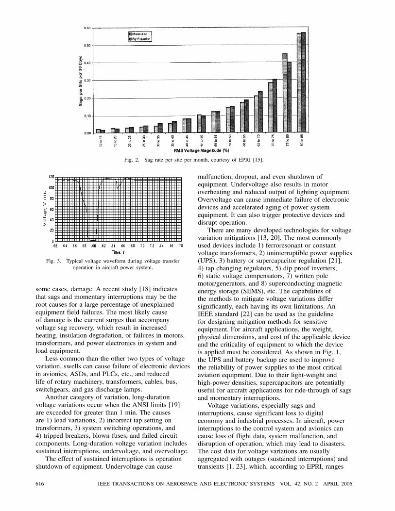
Fig. 2. Sag rate per site per month, courtesy of EPRI [15].
Fig. 3. Typical voltage waveform during voltage transferoperation in aircraft power system.
some cases, damage. A recent study [18] indicatesthat sags and momentary interruptions may be theroot causes for a large percentage of unexplainedequipment field failures. The most likely causeof damage is the current surges that accompanyvoltage sag recovery, which result in increasedheating, insulation degradation, or failures in motors,transformers, and power electronics in system andload equipment.Less common than the other two types of voltage
variation, swells can cause failure of electronic devicesin avionics, ASDs, and PLCs, etc., and reducedlife of rotary machinery, transformers, cables, bus,switchgears, and gas discharge lamps.Another category of variation, long-duration
voltage variations occur when the ANSI limits [19]are exceeded for greater than 1 min. The causesare 1) load variations, 2) incorrect tap setting ontransformers, 3) system switching operations, and4) tripped breakers, blown fuses, and failed circuitcomponents. Long-duration voltage variation includessustained interruptions, undervoltage, and overvoltage.The effect of sustained interruptions is operation
shutdown of equipment. Undervoltage can cause
malfunction, dropout, and even shutdown ofequipment. Undervoltage also results in motoroverheating and reduced output of lighting equipment.Overvoltage can cause immediate failure of electronicdevices and accelerated aging of power systemequipment. It can also trigger protective devices anddisrupt operation.There are many developed technologies for voltage
variation mitigations [13, 20]. The most commonlyused devices include 1) ferroresonant or constantvoltage transformers, 2) uninterruptible power supplies(UPS), 3) battery or supercapacitor regulation [21],4) tap changing regulators, 5) dip proof inverters,6) static voltage compensators, 7) written polemotor/generators, and 8) superconducting magneticenergy storage (SEMS), etc. The capabilities ofthe methods to mitigate voltage variations differsignificantly, each having its own limitations. AnIEEE standard [22] can be used as the guidelinefor designing mitigation methods for sensitiveequipment. For aircraft applications, the weight,physical dimensions, and cost of the applicable deviceand the criticality of equipment to which the deviceis applied must be considered. As shown in Fig. 1,the UPS and battery backup are used to improvethe reliability of power supplies to the most criticalaviation equipment. Due to their light-weight andhigh-power densities, supercapacitors are potentiallyuseful for aircraft applications for ride-through of sagsand momentary interruptions.Voltage variations, especially sags and
interruptions, cause significant loss to digitaleconomy and industrial processes. In aircraft, powerinterruptions to the control system and avionics cancause loss of flight data, system malfunction, anddisruption of operation, which may lead to disasters.The cost data for voltage variations are usuallyaggregated with outages (sustained interruptions) andtransients [1, 23], which, according to EPRI, ranges
616 IEEE TRANSACTIONS ON AEROSPACE AND ELECTRONIC SYSTEMS VOL. 42, NO. 2 APRIL 2006

Fig. 4. Comparison of standard voltage tolerance boundaries.
from $104 billion to $164 billion a year in the U.S.The cost estimates for some specific systems or events[24, 25] also appear in the literature but will not bediscussed here.The voltage variation ride-through capability of
equipment is an important measure for governmentand industry equipment procurement. Many equipmentvoltage tolerance standards have been developed forthat purpose. The ITI (CBEMA) curve by InformationTechnology Industry Council (ITI) [26] and SEMIF47 by Semiconductor Equipment ManufacturingInternational (SEMI) [27] are among the mostrecognized. In the semiconductor manufacturingindustry, sag ride-through is critical to materialgrowth and IC chip production. SEMI F47 is thus amore stringent standard for equipment procurementcompared with the ITI curve. The Federal AviationAdministration also has its own standard [28]. Acomparison of these standards is shown in Fig. 4.Also shown in Fig. 4 are the aircraft electric powersystem 400 Hz 115 V short- and long-durationvoltage variation tolerances [29]. In this figure thefollowing notations are used: ITI–ITI (CEBMA)curve; SEMI–SEMI F47; FAA–FAA-G-2100G;704–MIL-STD-704F; U–upper boundary; L–lowerboundary; N–normal; and A–abnormal.Note that the curves 704-N and 704-A are for
both power system and load equipment tolerance.Depending upon the criticality of equipment,MIL-STD-704F requires the equipment to maintainoperation without disruption, dropout withoutlosing data, or dropout without damage under theconditions of voltage transfer and abnormal operation.MIL-STD-704F requires the most critical equipmentto tolerate » 50 ms interruptions (as shown in Fig. 3)during special normal operations such as voltagetransfers, and up to 7 s of undervoltage in abnormaloperation conditions, during which time the mostcritical equipment must not be disrupted. Notice alsothat the ITI curve and FAA curve include transienttolerance, whereas MIL-STD-704F does not apply to
transient tolerance. Instead, subcycle voltage spikesare covered under MIL-STD-461D, the military EMIspecifications [30].For internationally traded product and equipment,
the dominant standards are those set forth byInternational Electrotechnical Commission (IEC),which cover the entire spectrum of electromagneticcompatibility (EMC) tests. For the voltagetolerance standards, IEC 61000-4-11 [31] andIEC 61000-4-34 [32], the equipment immunitytesting and measurement standards for voltagedips (equivalent to the IEEE standard terminologysags), short interruptions, and voltage variationsform ac inputs, are more widely used. Electricaland electronics equipment exporting to Europeancommunity must conform to these standards toobtain a CE marker, literally indicating a Europeanconformity. IEC 61000-4-11 and -34 are a pair ofstandards that apply to the equipment rated up to andabove 16 A, respectively. In terms of the toleranceon the depth and duration of dips, the IEC standardsuse slightly different specifications compared withSEMI F47. Above 200 ms, IEC 61000-4-11 and-34 are essentially the same as SEMI F47; below200 ms, IEC imposes a more stringent requirement.The comparison of IEC 61000-4-11 and -34 toother standards is also shown in Fig. 4. It should bepointed out that to implement the equipment immunitystandards, appropriate testing and measurementprocedures are important. An in-depth discussionon the approaches and procedures of evaluatingequipment sensitivity to voltage dips is provided in[33].
C. Waveform Distortion
Waveform distortions are steady-state disturbancephenomena. Transients do not belong to thiscategory even though they too distort waveforms.Waveform distortion includes, according to IEEESTD 1159-1995, dc offset, harmonics, interharmonics,notching, and broadband noise. The dc offset canresult from geomagnetic disturbances, half-waverectification, unbalanced 3-phase loads, or systemfaults. The military standard [29] restricts useof half-wave rectifiers in any aircraft utilizationequipment. dc offsets can cause abnormal tripping ofrelays, contactors, switchgears, and fault-protectioncircuitry [34, 35], thus leading to operation disruption.dc offsets can also result in flux saturation andadded heating and stress in motors, transformers,and magnetic-activated devices such as relays,contactors, and solenoids. Notching is caused bypower electronics switching. Deep notching can upsetthe state of digital electronics and affect the timingcircuitry that uses zero-crossings.The most prominent and also troublesome
waveform distortion is harmonics, which is also one
LIU ET AL.: POWER ANOMALY EFFECTS AND COSTS IN LOW-VOLTAGE MOBILE POWER SYSTEMS 617

TABLE IVHarmonic Current Generation from Equipment
Equipment THD Harmonics
Generator and transformer Due to flux saturation or mechanical reasons, relatively small voltage harmonics
6-pulse (CS) 24—30% 5th, 7th, 11th, 13th, 17th, : : :[41, 42]3Á TRU 6-pulse (VS) 30—67% 5th, 7th, 11th, 13th, 17th, : : :[41, 42]
12-pulse 10—20% 11th, 13th, 23rd, : : : [43, 44]
System 1Á Switched mode PS 70—90% All odd harmonicsRectifier PS 70% All odd harmonicsDigital PS 38% DC, 3rd predominant, [45]Phase-controlled converter 0—140% Varies with firing angle [38, 42]
ASD 42—140% All odd harmonics [46]PC or computer systems 58—115% DC, all odd harmonics [46, 47]
Load Printer 82.4% DC (60%), all harmonics up to 30th, [45]Oscilloscope 63.5% DC, high 2nd, 3rd, 5th, significant 4th, 9th, [45]Fluorescent Lamps 15—20% Predominant 3rd, [45]Search radar or HF radio 8—12% (loads to 12-pulse TRU) 11th, 13th, : : : [48]
of the most dynamic research areas in industry andacademia. More than a third of our collected literatureon power disturbances concerns harmonics. This isbecause harmonics cause reduced utilization capacityand reliability of electric power systems; these issuesbecome more critical as the use of power electronicsloads increases [36]. In aircraft, nearly 20% to 30%loads are nonlinear. Therefore, harmonic control isone of the key issues in aircraft electric power quality.Another issue yet to be addressed is the effect of amuch higher fundamental ac frequency (400 Hz)and its harmonics in aircraft systems, comparedwith 50/60 Hz in terrestrial systems, for which littleresearch can be found in the literature.There are two landmark reviews on harmonics
by IEEE task forces [37, 38]. These reviews outlinethe causes and effects of harmonics. The latestversion of the IEEE standard [39] provides harmoniccontrol guidelines for both harmonic voltage andcurrent, whereas the previous version [40] dealsonly with harmonic voltages. The update reflects theadvances of research in both the electric power andequipment manufacturing industries from 1981 to1993. However, since then there has been an explosiveuse of office, residential, and industrial nonlinearloads. In addition, many traditional linear devicessuch as motors and lighting equipment have changedto nonlinear versions due to the use of electronicpower conversion and control systems. In order toaddress the issue, significant research on mitigationtechnology for terrestrial 50/60 Hz systems has beendone in the last two decades to characterize systemreliability due to harmonic effects and its relatedeconomic impact.In aircraft electric power systems, there is a trend
towards increased use of nonlinear loads also. Allnonlinear loads draw distorted sinusoidal currentscontaining harmonic content. Due to finite bus andsource impedances, the voltage waveforms at buses
or sources become distorted, thus polluting the entiresystem. Harmonic generation in aircraft results fromtwo classes of sources: 1) nonlinear load equipment,and 2) power system equipment. Table IV listsharmonic generation from some typical equipment.Except for generators and transformers, the harmoniccontent and the total harmonic distortions (THDs)listed in Table IV refer to their current distortion forall other equipment. The levels of harmonic contentand THD depend on particular equipment and itsdesign.Table V summarizes the effects of voltage and
current harmonics on equipment. As can be seen,almost all equipment is affected. In particular, theoverall system reliability is severely reduced dueto component accelerated aging, premature failure,malfunction, and disruption. Several studies variouslycharacterize the life expectation of components underthe effect of voltage and current harmonics. Forexample, incandescent lamps lose 47% of the usefullife if the harmonic voltage is 105% of the normal[38]; the useful motor life will be cut in half for every8±C temperature increase due to harmonic current[49]; another study [50] indicates that in the presenceof both harmonic voltage and current, electricalstress is the dominant factor in reducing the life ofenergy components. Under multi-stresses, the lifeof motors is reduced to 54%—59%, cables 48%, andcapacitors 40%. The effect of voltage distortion onaging acceleration under partial discharge activity isdiscussed by Fabiani and Montanari [51]. In militaryaircraft, controlling harmonics (both conducted andradiated) from power leads is specified in the standardMIL-STD-461D [33]. MIL-STD-704F does notimpose specific limits on current harmonics, but doesrequire that, when the aircraft designer has finishedthe complete system, the voltage distortion be limitedto 5% plus a distortion spectrum limit for individualfrequency components of voltage distortion.
618 IEEE TRANSACTIONS ON AEROSPACE AND ELECTRONIC SYSTEMS VOL. 42, NO. 2 APRIL 2006

TABLE VEffects of Harmonics
Effect and Symptom Equipment
1. Increased reactive power burden–Harmonic loading, lowpower factor, capacity derating
System components: generators, transformers, motors, andcables, buses, circuit breakers, capacitors, etc.
2. Decreased efficiency–Increased thermal loss All system and load equipment
3. Accelerated aging and premature failure–Thermal overloading,distorted voltage stress, insulation deterioration
Generators, motors, transformers, capacitors, cables and powerelectronics components, incandescent and gas discharge lamps
4. Reduced reliability–Increased equipment and componentmalfunction and disruption
Relays, contactors, fuses, circuit breakers, fault-protectioncircuitry, zero-crossing timing circuitry, peak sensing circuitry
5. Reduced stability Motor torque pulsating, mechanical resonance, light outputvariations
6. Communication interference–Noise, cross talk, disruption Communication and wireless controlled equipment (straycoupling with harmonic emissions)
The effectiveness of harmonic mitigationmethods applied to a commercial office buildingis discussed by Key and Lai [52, 53]. The modelfor the building electric power system is similarto an aircraft electric power system in many waysexcept that it is connected to a power grid. It includesthe following major equipment: 1) a distributiontransformer (600 kVA); 2) a service entrance (mainbus 480 V, 16% THD) connecting to 1Á and 3Á largelinear and nonlinear loads (ASD, 277 V lighting,UPS, large computers, 50—150% THD), and toa service transformer (480/208 V, 30% THD);3) a subpanel or load center (120 V panel, 90%THD); 4) and multiple branch circuits or cordconnections (computers, etc. 100% THD). Thepaper concludes that the most effective approachto eliminate harmonics is a built-in power-factorcorrection circuit or a boost converter inside electronicequipment. The next best option is using variousharmonic filters, of which the location is criticalfor reducing losses. Namely, the parallel-connectedresonant filter (PCRF) and series-connected resonantfilter (SCRF) are recommended for branch circuitor cord connected level near the load equipment.These filters are cost effective and in most casesthe combination of PCRF and SCRF is used toblock more harmonics. The neutral current filter(ZCF), zigzag filter (ZZF), and active power filter(APF) are suggested for subpanel or load centerlevel. The ZCF and ZZF work best for eliminatingtriplens and reducing the neutral current. The neutralcurrent primarily consists of zero-sequence harmonics(3rd order harmonic and its triplens (9th, 15th,21st, : : :)). Zero-sequence harmonics are principallythe by-product of switched-mode power supplytechnology which is used in avionics, motor drives,lighting systems, and in virtually all other low-powerelectronic devices. These harmonics do not cancel butrather add up in the neutral conductor, which causesoverheating of the neutral conductor.
The harmonic cost and mitigation benefits arealso characterized by Key and Lai [53, 54]. Usinga similar building system with four types of cables(500 kcmil, 4/0, 1/0 and 12 AWG) and detailedharmonic loss model, the total harmonic loss of cablesand transformers is 4,802 W for every 60 kW load,and the yearly added cost is $2,101. This rationalecan be used to estimate the total harmonic loss in theU.S. In the year 1997, the net electricity generationis 3492.2 billion kWh [55]. This yields an averagedpower generation of about 398.7 GW. The lostgeneration due to harmonics is then 31.91 GW, andthe added cost is $13.96 billion for the year 1997.Assuming the same cost ratio applies in the year2001, the harmonics loss would have been $14.94billion (the net electricity generation is 3736.6 billionkWh in 2001). In terms of the rationale of militaryspending to the U.S. GDP, the annual added cost dueto harmonics in military electric power installationsis $716.3 million for the year 2001. Note that thecalculation is for cable and transformer harmonic lossonly. It does not include the aging and failure cost ofload equipment, and does not account for the powerloss from load equipment. It should be pointed outthat the model used by Key and Lai is a commercialbuilding typically with a high concentration ofnonlinear loads, which may not be applicable toan industrial site where the majority of loads areac motors. Therefore, the estimate of the cost dueto harmonics needs to be improved by assessingthe differences of the nonlinear loads percentage invarious end-user facilities compared with those of acommercial building.
D. Voltage Imbalance
Voltage imbalance, or unbalance, can result fromunbalanced 3Á loads due to unevenly distributedsingle-phase loads, from malfunctions of automaticpower-factor correction equipment and voltage
LIU ET AL.: POWER ANOMALY EFFECTS AND COSTS IN LOW-VOLTAGE MOBILE POWER SYSTEMS 619
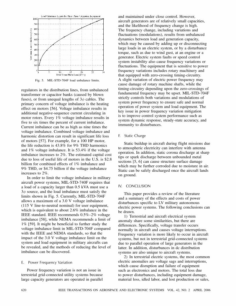
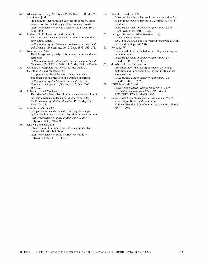
Fig. 5. MIL-STD-704F load unbalance limits.
regulators in the distribution lines, from unbalancedtransformer or capacitor banks (caused by blownfuses), or from unequal lengths of 3Á cables. Theprimary concern of voltage imbalance is the heatingeffect on motors [56]. Voltage imbalance results inadditional negative-sequence current circulating inmotor rotors. Every 1% voltage imbalance results infive to six times the percent of current imbalance.Current imbalance can be as high as nine times thevoltage imbalance. Combined voltage imbalance andharmonic distortion can result in significant life lossof motors [57]. For example, for a 100 HP motor,the life reduction is 43.8% for 9% THD harmonicsand 1% voltage imbalance. It is 53.4% if the voltageimbalance increases to 2%. The estimated capital costdue to loss of useful life of motors in the U.S. is $2.8billion for combined effects of 1% imbalance and9% THD, or $4.75 billion if the voltage imbalanceincreases to 2%.In order to limit the voltage imbalance in military
aircraft power systems, MIL-STD-740F requires thata load of a capacity larger than 0.5 kVA must use a3Á source, and the load imbalance must satisfy thelimits shown in Fig. 5. Currently, MIL-STD-704Fallows a maximum of a 3.0 V voltage imbalance(115 V line-to-neutral nominal) for user equipment,which is equivalent to about 2.6% imbalance in theIEEE standard. IEEE recommends 0.5%—2% voltageimbalance [58], while NEMA recommends a limit of1% [59]. It might be beneficial to further study thevoltage imbalance limit in MIL-STD-704F comparedwith the IEEE and NEMA standards, so that theimpact of the 3.0 V voltage imbalance limit on thesystem and load equipment in military aircrafts canbe revealed, and the methods of reducing the level ofimbalance can be discovered.
E. Power Frequency Variation
Power frequency variation is not an issue interrestrial grid-connected utility systems becauselarge capacity generators are operated in parallel
and maintained under close control. However,aircraft generators are of relatively small capacities,and the likelihood of frequency change is high.The frequency change, including variations andfluctuations (modulations), results from unbalanceddynamics between load and generation capacity,which may be caused by adding up or disconnectinglarge loads in an electric system, or by a disturbancetorque, such as due to wind gust, at an engine or agenerator. Electric system faults or speed controlsystem instability also cause frequency variations orfluctuations. The equipment that is sensitive to powerfrequency variations includes rotary machinery andthat equipped with zero-crossing timing-circuitry.A slight variation of electric power frequency maycause damage of rotary machine shafts, while thetiming-circuitry depending upon the zero-crossings offundamental frequency may be upset. MIL-STD-704Fstrictly controls both variations and modulations ofsystem power frequency to ensure safe and normaloperation of power system and load equipment. Thekey issue in power frequency variation mitigationis to improve control system performance such assystem dynamic response, steady-state accuracy, andimmunity to disturbances.
F. Static Charge
Static buildup in aircraft during flight missions dueto atmospheric electricity can interfere with antennaoperation. In addition, static corona discharge at sharptips or spark discharge between unbounded metalsections [5, 6] can cause structure surface damagewhich may be further corroded due to moisture in air.Static can be safely discharged once the aircraft landson ground.
IV. CONCLUSION
This paper provides a review of the literatureand a summary of the effects and costs of powerdisturbances specific to LV military autonomouselectric power systems. The following conclusions canbe drawn.1) Terrestrial and aircraft electrical system
anomaly share some similarities, but there aredifferences. Specifically, voltage transfer occursnormally in aircraft and causes voltage interruptions.Frequency variation is more likely to occur in aircraftsystems, but not in terrestrial grid-connected systemsdue to parallel operation of large generators in thelatter. In addition, disturbances in dc distributionsystems are also unique to aircraft systems.2) In terrestrial electric systems, the most common
electric anomalies are voltage sags and interruptions,which cause disruption and failure of equipmentsuch as electronics and motors. The total loss dueto power disturbances, including equipment damage,material loss, idled labor, and lost production or sales,
620 IEEE TRANSACTIONS ON AEROSPACE AND ELECTRONIC SYSTEMS VOL. 42, NO. 2 APRIL 2006

costs the U.S. economy 1.2% to 1.9% of its GDP, or$119—$188 billion a year (in 2001 dollar value).3) In aircraft electric systems, electric anomalies
damage user equipment such as avionics and motors,and disrupt system operation, which may lead toaircraft fatalities. Using the rationale of the militaryspending to the GDP, it is estimated that the electricanomalies cost the DOD about $5.8—9.2 billion a year(in the 2001 dollar value). To improve the estimate,the detailed military equipment capital costs, thePD sensitivity, the PD frequency of occurrence inthe military systems, and other consequent costsresulted from PD effects must be studied and takeninto account.4) Harmonic pollution is a serious concern for the
electric system reliability and economy. Harmonicsresult in reduced system capacity, acceleratedcomponent aging and premature failure, and reducedefficiency. It is estimated that the power loss due toharmonics in cables and transformers is 31.4 GW andan annual added cost to the U.S. economy is $14.94billion (in 2001). Equivalently, it costs the DOD about$716.3 million a year due to harmonic loss in militaryelectric power installations in 2001. Again, to improvethe estimation, harmonic characteristics must bestudied in military electric systems. In particular, theeffects due to a higher system fundamental frequency(400 Hz) and its harmonics in aircraft electric powersystems should be thoroughly investigated to addressthe issue.5) Voltage imbalance tolerance (2.6%) in
MIL-STD-704F is slightly out of the IEEErecommended value range (0.5—2%). Voltageimbalance can cause considerable motor heating andresultant loss of useful life. 53.4% of the useful life ofa 100-HP motor is lost for the combined effects of 9%THD and 2% voltage imbalance. The estimated capitalcost due to motor life loss in the U.S. is $4.75 billionunder the same effects. It will be beneficial to conductfurther studies to investigate the effects of the voltageimbalance tolerance in MIL-STD-704F compared withthe IEEE and NEMA standards.6) Finally, characterization of all electric anomalies
in military electric systems such as those in aircrafts,naval ships, and land-based military vehicles shouldbe conducted to better determine the effects andcosts, so that appropriate mitigation methods andtechnologies can be developed and applied forreducing the life cycle cost of equipment.
REFERENCES
[1] EPRIThe cost of power disturbances to industrial and digitaleconomy companies.EPRI Technical report 1006274, June 2001.
[2] Bureau of Economic Analysis (BEA)BEA News.BEA 04-36, http://www.bea.doc.gov/bea/newsrelarchive/2004/gdp204a.pdf, retrieved on Sept. 2, 2004.
[3] CDI2001—2002 Military Almanac.http://www.cdi.org/products/almanac0102.pdf, retrievedon Sept. 1, 2004.
[4] IEEE Standards BoardIEEE Recommended Practice for Monitoring ElectricPower Quality.IEEE STD 1159-1995, June 1995.
[5] Braidotti, V., Zaninelli, D., and Zanini, A.Power quality studies on aircraft electric systems.In Proceedings of Ninth International Conference onHarmonics and Quality of Power, vol. 2, Oct. 2000,625—632.
[6] Faranda, R., Zaninelli, D., and Zanini, A.Electric power quality on aircraft: Analysis andpropagation of disturbances.IEEE Power Engineering Society Summer Meeting, vol. 1,July 2001, 222—227.
[7] IEEE Standards BoardIEEE Surge Protection Standards Collection.IEEE STD C62-1992, 1992.
[8] Martzloff, F.Surge protection in low-voltage AC power circuits–Ananthology.NISTIR 6714-1, http://www.eeel.nist.gov/811/spd-anthology/AnnotatedBibliography.pdf, Dec. 2002,retrieved on Sept. 10, 2004.
[9] Swiss ReTwister! The professional reinsurer’s perspective.Sigma report 1/2000, Swiss Re, Zurich, 2000.
[10] Kithil, R.Results of investigations into annual USA lightning costsand losses.National Lightning Safety Institute, Louisville, CO,http://www.lightningsafety.com/nlsi lls/nlsi annual usalosses.htm, retrieved on Sept. 10, 2004.
[11] Gomez, J., Morcos, M., Reineri, C., and Campetelli, G.Behavior of induction motor due to voltage sags andshort interruptions.IEEE Transactions on Power Delivery, 17, 2 (Apr. 2002),434—440.
[12] Gomez, J., and Morcos, M.Voltage sag and recovery time in repetitive events.IEEE Transactions on Power Delivery, 17, 4 (Oct. 2002),1037—1043.
[13] PIER/EPRIVoltage-sag solutions for industrial customers.EPRI report 1007485, Palo Alto, CA, California EnergyCommission, Sacramento, CA, Jan. 2003.
[14] Koval, D., and Hughes, M.Canadian national power quality survey: Frequency ofindustrial and commercial voltage sags.IEEE Transactions on Industry Applications, 33, 3(May/June 1997), 622—627.
[15] EPRIDistribution system power quality assessment: Phase II:Voltage sag and interruption analysis.EPRI Technical report 1001678, Mar. 2003.
[16] Pohjanheimo, P., and Lehtonen, M.Equipment sensitivity to voltage sags-test results forcontactors, PCs and gas discharge lamps.In Proceedings of the 10th International Conference onHarmonics and Quality of Power, vol. 2, Oct. 2002,559—564.
[17] PIER/EPRICharacterizing the impact of power quality onprogrammable logic controller with and withoutpower-conditioning devices.EPRI report 1001072, Palo Alto, CA, California EnergyCommission, Sacramento, CA, Oct. 2000.
LIU ET AL.: POWER ANOMALY EFFECTS AND COSTS IN LOW-VOLTAGE MOBILE POWER SYSTEMS 621

[18] Bendre, A., Divan, D., Kranz, W., and Brumsickle, W.Equipment failure caused by power quality disturbances.Presented at the IEEE 39th IAS Annual MeetingConference record CD 04CH37569C, Seattle WA, Oct.2004.
[19] ANSI American National Standards for Electric PowerSystems and Equipment–Voltage ratings (60 Hz).ANSI C84.1-1989, 1989.
[20] Degeneff, R., Barss, R., Carnovale, D., and Raedy, S.Reducing the effect of sags and momentary interruptions:a total owning cost prospective.In Proceedings of Ninth International Conference onHarmonics and Quality of Power, vol. 2, Oct. 2000,397—403.
[21] Kazimierczuk, M., and Cravens, R.Application of super capacitors for voltage regulation inaircraft distributed power systems.In Proceedings of the 27th Annual IEEE Power ElectronicsSpecialists Conference (PESC ’96 Record), vol. 1, June1996, 835—841.
[22] IEEE Guide for Service to Equipment Sensitive to MomentaryVoltage Disturbances.IEEE STD 1250-1995, June 1995.
[23] Lawton, L., Sullivan, M., Van Liere, K., Katz, A., andEto, J.A framework and review of customer outage costs:Integration and analysis of electric utility outage costsurveys.Lawrence Berkeley National Laboratory reportLBNL-54365, Nov. 2003.
[24] Koval, D., Beristain, J., and Bent, D.Evaluating the reliability cost of computer systeminterruptions due to power system disturbances.IEEE Transactions on Industry Applications, 25, 2(Mar./Apr. 1989), 248—256.
[25] Eto, J., Koomey, J., Lehman, B., Martin, N., Mills, E.,Webber, C., and Worrel, E.Scoping studies on trends in the economic value ofelectricity reliability to the U.S. economy.Lawrence Berkeley National Laboratory reportLBNL-47911, June 2001.
[26] Information Technology Industry Council (ITIC)ITI (CEBMA) curve application note.http://www.itic.org/technical/iticurv.pdf. Retrieved onSept. 15, 2004.
[27] Power Standards Lab (PSL)http://www.powerstandards.com/SEMIF47.htm. Retrievedon Sept. 15, 2004.
[28] Federal Aviation Administration Specification: ElectronicEquipment, General Requirements.Federal Aviation Administration, Departmentof Transportation, FAA-G-2100G, Oct. 2001.http://www.faa.gov/asd/standards/faa-g-2100g.pdf.Retrieved on Sept. 15, 2004.
[29] MIL-STD-704FAircraft electric power characteristics.Department of Defense Interface Standard, Mar. 2004.
[30] MIL-STD-461DRequirements for the control of electromagneticinterference emissions and susceptibility.Department of Defense Interface Standard, Jan. 1993.
[31] IEC 61000-4-11Electromagnetic compatibility (EMC)–Part 4-11:Testing and measurement techniques–Voltage dips, shortinterruptions and voltage variations immunity tests.Ed. 2.0, Mar. 2004.
[32] IEC 61000-4-34Electromagnetic compatibility (EMC)–Part 4-34: Voltagedips, short interruptions and voltage variations immunitytests for equipment with input more than 16 A per phase.CDV, July 2004.
[33] Stephens, M., McGranaghan, M., and Bollen, M.Evaluating voltage dip immunity of industrial equipment.Appeared as an online multimedia presentation athttp://www.f47testing.com/voltage dip immunity.html.Retrieved on Aug. 25, 2005.
[34] Chapman, F., and Hammonds, B.The effect of dc offset on instantaneous operatingcharacteristics of low-voltage circuit breakers.IEEE Transactions on Industry Applications, 33, 6(Nov./Dec. 1997), 1488—1492.
[35] Stringer, N.The effect of dc offset on current-operated relays.IEEE Transactions on Industry Applications, 34, 1(Jan./Feb. 1998), 30—34.
[36] Redl, R., Tenti, P., and Daan van Wyk, J.Power electronics’ polluting effects.IEEE Spectrum, 34, 5 (May 1997), 32—39.
[37] IEEE Task ForceThe effects of power system harmonics on power systemequipment and loads.IEEE Transactions on Power Apparatus and Systems,PAS-104, 9 (Sept. 1985), 2555—2563.
[38] Wagner, V., Balda, J., Griffith, D., McEachern, A., et al.Effects of harmonics on equipment.IEEE Transactions on Power Delivery, 8, 2 (Apr. 1993),672—680.
[39] IEEE Recommended Practices and Requirements forHarmonic Control in Electric Power Systems.ANSI/IEEE STD 519-1992, 1992.
[40] IEEE Guide for Harmonic Control and ReactiveCompensation of Static Power Converters.ANSI/IEEE STD 519-1981, Apr. 1981.
[41] Rice, D.A detailed analysis of six-pulse converter harmoniccurrents.IEEE Transactions on Industry Applications, 30, 2(Mar./Apr. 1994), 294—304.
[42] Melhorn, C., and McGranaghan, M.Interpretation and analysis of power qualitymeasurements.IEEE Transactions on Industry Applications, 31, 6(Nov.—Dec. 1995), 1363—1370.
[43] Gong, G., Drofenik, U., and Kolar, J.12-pulse rectifier for more electric aircraft applications.In Proceedings of IEEE International Conference onIndustrial Technology, vol. 2, Dec. 2003, 1096—1101.
[44] Andrews, D., Bishop, M., and Witte, J.Harmonic measurements, analysis, and power factorcorrection in a modern steel manufacturing facility.IEEE Transactions on Industry Applications, 32, 3(May/June 1996), 617—624.
[45] Sharma, V., Moinuddin, M., Doja, Ibraheem and M. KhanPower quality assessment and harmonic comparison oftypical nonlinear electronic loads.In Proceedings of the IEEE International Conference onIndustrial Technology, vol. 1, Jan. 2000, 729—734.
[46] Briggs, S., Savignon, D., Krein, P., and Kim, M.The effects of nonlinear loads on EMI/RFI filters.IEEE Transactions on Industry Applications, 31, 1(Jan.—Feb. 1995), 184—189.
622 IEEE TRANSACTIONS ON AEROSPACE AND ELECTRONIC SYSTEMS VOL. 42, NO. 2 APRIL 2006
[47] Mansoor, A., Grady, W., Staats, P., Thallam, R., Doyle, M.,and Samotyj, M.Predicting the net harmonic currents produced by largenumbers of distributed single-phase computer loads.IEEE Transactions on Power Delivery, 10, 4 (Oct. 1995),2001—2006.
[48] Ferland, G., Chikhani, A., and Cartier, J.Harmonic and transient analysis of an aircraft electricaldistribution system.In Proceedings of the Canadian Conference on Electricaland Computer Engineering, vol. 2, Sept. 1993, 668—671.
[49] Inan, A., and Attar, F.The life expectancy analysis for an electric motor due toharmonics.In Proceedings of the 9th Mediterranean ElectrotechnicalConference (MELECON’98), vol. 2, May 1998, 997—999.
[50] Caramia, P., Carpinelli, G., Verde, P., Mazzanti, G.,Cavallini, A., and Montanari, G.An approach to life estimation of electrical plantcomponents in the presence of harmonic distortion.In Proceedings of 9th International Conference onHarmonics and Quality of Power, vol. 3, Oct. 2000,887—892.
[51] Fabiani, D., and Montanari, G.The effect of voltage distortion on ageing acceleration ofinsulation systems under partial discharge activity.IEEE Electrical Insulation Magazine, 17, 3 (May/June2001), 24—33.
[52] Key, T. S., and Lai, J-S.Comparison of standards and power supply designoptions for limiting harmonic distortion in power systems.IEEE Transactions on Industry Applications, 29, 4(July/Aug. 1993), 688—695.
[53] Lai, J-S., and Key, T. S.Effectiveness of harmonic mitigation equipment forcommercial office buildings.IEEE Transactions on Industry Applications, 33, 4(July/Aug. 1997), 1104—1110.
[54] Key, T. S., and Lai, J-S.Costs and benefits of harmonic current reduction forswitch-mode power supplies in a commercial officebuilding.IEEE Transactions on Industry Applications, 32, 5(Sept.—Oct. 1996), 1017—1025.
[55] Energy Information Administration (EIA).Annual energy review2002. http://www.eia.doe.gov/aer/pdf/pages/sec8 8.pdf.Retrieved on Sept. 14, 2004.
[56] Kersting, W.Causes and effects of unbalanced voltages serving aninduction motor.IEEE Transactions on Industry Applications, 37, 1(Jan./Feb. 2001), 165—170.
[57] de Abreu, J., and Emanuel, A.Induction motor thermal aging caused by voltagedistortion and imbalance: Loss of useful life and itsestimated cost.IEEE Transactions on Industry Applications, 38, 1(Jan./Feb. 2002), 12—20.
[58] IEEE Standards BoardIEEE Recommended Practice for Electric PowerDistribution for Industrial Plants (Red Book).ANSI/IEEE STD 141-1993, 1993.
[59] National Electrical Manufacturers Association (NEMA)Standard for Motors and Generators.National Electrical Manufacturers Association, NEMAMG-1, 1993.
LIU ET AL.: POWER ANOMALY EFFECTS AND COSTS IN LOW-VOLTAGE MOBILE POWER SYSTEMS 623
Shengyi Liu (S’94–M’96–SM’02) received the Ph.D. in electrical engineeringin 1995 from the University of South Carolina, Columbia.He was senior research and development engineer at InnerLogic, Inc. from
1995—1999, and is now research associate professor in the Department ofElectrical Engineering at the University of South Carolina. His research interestsinclude design and development of energy storage technologies, renewables,physical electronics-based devices, power semiconductor devices and converters;energy efficiency and power quality improvement in autonomous power systems;distributed power generation for the future energy network; and modeling andsimulation of interdisciplinary systems.Dr. Liu is a licensed professional engineer in the State of South Carolina, and
a Member of AIAA.
Charles H. Singer received the B.S. degree in electrical engineering, University of Maryland, College Park, in1987.He was project engineer, Electric Power Systems, NSWCCD/Annapolis, from 1988—1995, project engineer,
Electrical Power Systems, NAVAIR from 1995—1997, and senior project engineer, Electrical Power Systems,NAVAIR from 1997—2004. From 1997 to the present, as senior electrical project engineer. Mr. Singer has beenresponsible for the full life cycle systems engineering management and systems integration of aircraft electricalpower systems. He is team technical leader for the development of arc fault circuit breakers for military andcommercial aircraft under ONR Future Naval Capabilities, Total Ownership Cost Program.Mr. Singer is a member of the Society of Automotive Engineers.
Roger A. Dougal (S’74–M’82–SM’94) received the Ph.D. degree in electricalengineering at Texas Tech University, Lubbock, in 1983.He joined the faculty at the University of South Carolina in 1983 where he is
now the Director of the Virtual Test Bed project. His research interests includepulsed power systems, especially plasma-based switching devices, and electronbeam generation and applications, and laser systems and electro-optics.Dr. Dougal received the Samuel Litman Distinguished Professor of
Engineering award, and has been honored as a Carolina Research Professor.
624 IEEE TRANSACTIONS ON AEROSPACE AND ELECTRONIC SYSTEMS VOL. 42, NO. 2 APRIL 2006