Power and Control TYPE - stabiloy.com · 26 1999 November/December BY RAVI GANATR Power and Control...
9
26 1999 November/December BY RAVI GANATR Power and Control T YPE Power and Control T YPE 26 1999 November/December IAEI NEWS
Transcript of Power and Control TYPE - stabiloy.com · 26 1999 November/December BY RAVI GANATR Power and Control...
26 1999 November/December
BY RAVI GANATR
Power and Control
T Y P E Power and Control
T Y P E 26 1999 November/DecemberIAEI NEWS

IAEI NEWS 1999 November/Decem-
RA
This article
discusses how the
requirements in both the
installation code and the
product standard are
utilized to manufacture and
install power and control
tray cable, Type TC,
products that are suitable
for various applications.
Where appropriate,
alternate wiring methods
are identified to provide
some useful comparison.
Also, some of the applicable
requirements in Canada and
Mexico1 are identified and
discussed to provide a North
American perspective.
Tray Cable:
TCTray Cable:
TCIAEI NEWS 1999 November/Decem-
ber 27
28 1999 November/December
Installation andApplicationsRequirements
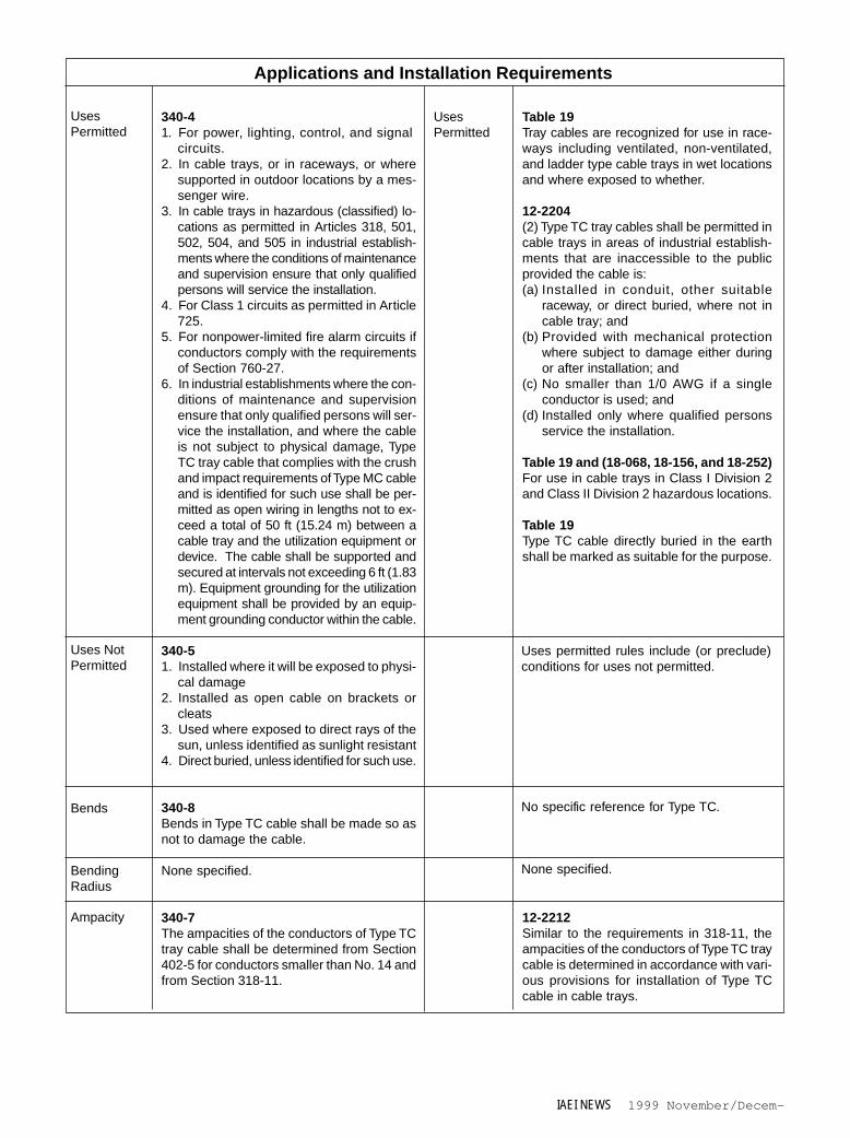
Table 1 (pages 32-34) provides a briefcomparison of installation and applica-tions requirements for Type TC traycables in Canada and the US. Significantrequirements for product recognitionand application are identified. SinceType TC cables are typically used incable trays, references related to cabletrays are also identified. For completedetails, references provided in the tableshould be consulted.
In the US, the National Electrical
Code (NEC), NFPA 70 standard, recog-nizes various types of wire and cableproducts and also defines requirementsfor their uses and installations for in-tended applications. Most, if not all, ofthese products are manufactured andlisted in accordance with applicableproduct standards, generally developedby the Underwriters Laboratories (UL).Article 318 defines cable trays, in 318-2.Cable tray installations are used morecommonly in industrial establishmentsto provide flexibility in wiring of pro-cess equipment. In accordance with318-3, cable tray installations are notlimited to industrial establishments.However, single conductor cables, pro-vided they are identified for use in cabletrays, are limited to industrial establish-ments only in accordance with 318-3(b)(1).
Article 340 of the NEC recognizesType TC products and defines require-ments for their uses and installations incable trays, in raceways, or where sup-ported by a messenger wire. UL Stan-dard 1277, Electrical Power and Con-trol Tray Cables with Optional Optical-Fiber Members, defines prescriptive andperformance requirements for Type TCproducts. For their use in cable trays,the suitability of single conductorcables, which are recognized in Table
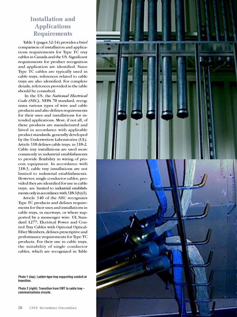
Photo 1 (top): Ladder-type tray supporting conduit attransition.
Photo 2 (right): Transition from EMT to cable tray –communications circuits.
IAEI NEWS 1999 November/Decem-
310-13, is evaluated in accordance withtheir respective product standards.
In Canada, the Canadian Electrical
Code (CEC) Part I, CSA Standard C22.1,recognizes various types of wire andcable products and also defines require-ments for their uses and installations forintended applications. All of these prod-ucts are manufactured and listed in ac-cordance with applicable product stan-dards listed in Appendix A of the CECPart II.2 These standards are developedby the Canadian Standards Association(CSA). In Canada, a cable tray is consid-ered a “raceway.” Unlike US, Type TC traycables can be either single or multi-con-ductor product in accordance with CEC.Also, tray cable in Canada also includesmedium voltage power cables. Type TCtray cables shall be permitted in cabletrays only in areas of industrial establish-ments that are inaccessible to the pub-lic, as an alternate to the main rule whichrequires that the conductors used in cabletrays in all areas shall have a continuousmetal sheath or interlocking armor. Simi-lar to US, single conductor Type TC traycables shall not be smaller than 1/0 AWG.
Cable trays provide the needed flex-ibility in circuit layouts in various indus-trial establishments, such as those foundin petro-chemical, pulp and paper, tex-tile, mining, etc. Wire and cable prod-ucts used in various non-raceway appli-cations in these industries require supe-rior mechanical, flame test, and coldtemperature handling properties.
Armored cables, such as Type MCCables in US and Types AC90, ACWU90and TECK90 in Canada, have been theprimary choice for these applications.This is because these products can beinstalled by themselves or in cabletrays. Type TC cables require a protec-tion when outside of the cable trayswhile armored cables may not requiresuch protection in most cases.
Inherent construction design ofarmored cables provides a better
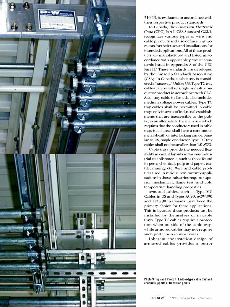
Photo 3 (top) and Photo 4: Ladder-type cable tray andconduit supports at transition points.
30 1999 November/December
opportunity to attain higher levels of mechanical perfor-mance, flame test performance for the overall cableconstruction, a higher level of insulating properties forthe conductor insulation, and a higher level of coldtemperature properties for the cable. Similar level ofachievement is difficult with Type TC products, especiallywhen the jacket alone cannot provide the neededperformance for all different needs.
Additional applications, such as for control and sig-nal circuits, of Type TC cables are identified in Table 1.The installation requirements for various wire and cableproducts in cable trays are provided in the code refer-ences for cable trays in Table 1. In particular, these ref-erences should be consulted for clearances between thecable trays, spacing of conductors and cables within acable tray, securing of conductors and cables within acable tray, etc. These installation requirements for cabletrays determine permitted ampacity for conductors andcables installed in a given cable tray.
Mechanical loading of trays is also a critical factor forproper installation of cable trays. In general, Type TCtray cables provide an advantage over heavier armoredcables. Generally, the weight of these products woulddecrease in the following order: armored cables withcopper conductors, tray cables with copper conductors,armored cables with electrically equivalent size alumi-num conductors, and tray cables with electrically equiva-lent size aluminum conductors.
Construction and PerformanceRequirements
Table 1 also provides a comparison of the construc-
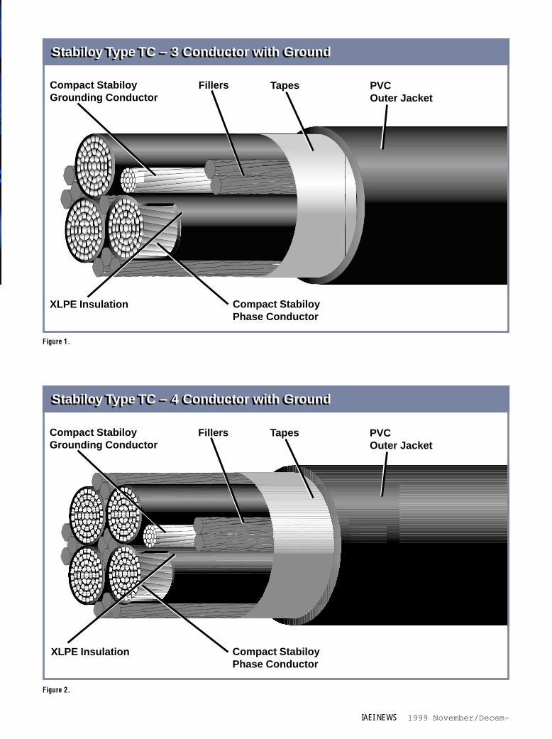
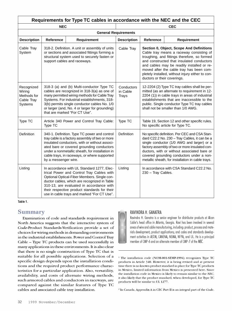
tion and performance requirements for Type TC traycables in two countries. With few exceptions, the re-quirements are very similar. Typical constructions of TypeTC with three and four conductors with an equipmentgrounding conductor for power applications are shownin Figures 1 and 2 (page 31).
Insulated conductors recognized in Table 310-13of the NEC are cabled together with or without theequipment grounding conductor and fillers. Conduc-tor types used most commonly for 600 V rated TypeTC products include THHN/THWN, XHHW, and RHH/RHW. For 2000 V rated Type TC products, conductortypes used include RHH/RHW recognized in Table310-62 of the NEC. A separator tape is used to wrap
the assembly of conductors. An overall jacket is thenapplied over the assembly.
Materials for conductor insulation, fillers, tapes,and jacketing play an important role in delivering therequired performance in accordance with the listingrequirements, optional requirements, customerspecifications and industry practices for Type TCproducts. A balance between the electrical ,mechanical and flame test properties of the insulationtype; mechanical and flame test properties of theoverall construction; and required optionalperformance capabilities is arrived at by the users invarious industrial establishments for their specificneeds. Construction capable of meeting therequirements for a higher level of low temperaturehandling, a higher level of vertical flame test, for alower level of acid gases, etc., is different than theconstruction capable of meeting the normalrequirements for the same properties.
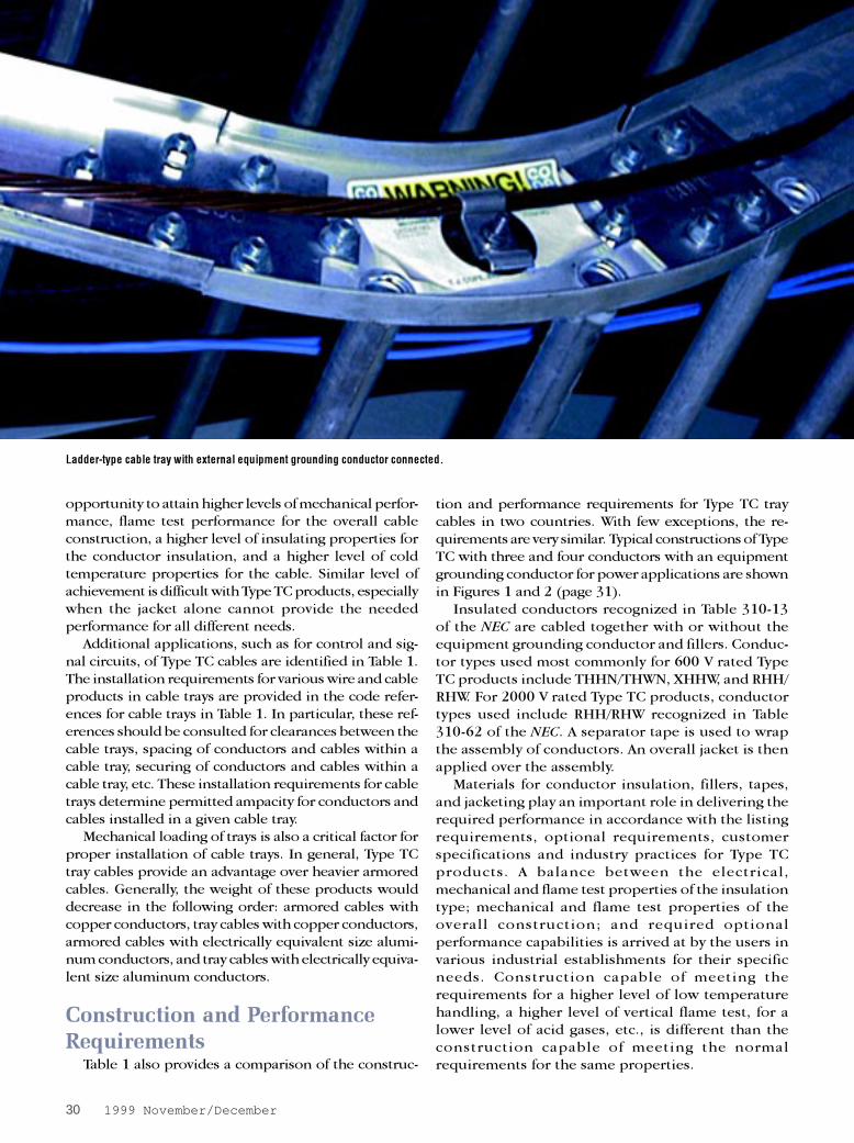
Ladder-type cable tray with external equipment grounding conductor connected.
IAEI NEWS 1999 November/Decem-
Stabiloy Type TC – 4 Conductor with GroundStabiloy Type TC – 4 Conductor with Ground
PVCOuter Jacket
XLPE Insulation Compact StabiloyPhase Conductor
Compact StabiloyGrounding Conductor
Fillers Tapes
Figure 2.
Stabiloy Type TC – 3 Conductor with GroundStabiloy Type TC – 3 Conductor with Ground
Figure 1.
PVCOuter Jacket
XLPE Insulation Compact StabiloyPhase Conductor
Compact StabiloyGrounding Conductor
Fillers Tapes
32 1999 November/December
General Requirements
Description Reference Requirement Description Reference Requirement
Requirements for Type TC cables in accordance with the NEC and the CECNEC CEC
Section 0, Object, Scope And DefinitionsCable tray means a raceway consisting oftroughing, and fittings therefore, so formedand constructed that insulated conductorsand cables may be readily installed or re-moved after the cable tray has been com-pletely installed, without injury either to con-ductors or their coverings.
12-2204 (2) Type TC tray cables shall be per-mitted (as an alternate to requirement in 12-2204 (1)) in cable trays in areas of industrialestablishments that are inaccessible to thepublic. Single conductor Type TC tray cablesshall not be smaller than 1/0 AWG.
Table 19, Section 12 and other specific rules.No specific article for Type TC.
No specific definition. Per CEC and CSA Stan-dard C22.2 No. 230 – Tray Cables, it can be asingle conductor (1/0 AWG and larger) or afactory assembly of two or more insulated con-ductors, with or without associated bare orcovered grounding conductors under a non-metallic sheath, for installation in cable trays.
In accordance with CSA Standard C22.2 No.230 – Tray Cables.
Type TC Type TC
Definition Definition
Listing Listing
Cable TraySystem
318-2. Definition. A unit or assembly of unitsor sections and associated fittings forming astructural system used to securely fasten orsupport cables and raceways.
318-3 (a) and (b) Multi-conductor Type TCcables are recognized in 318-3(a) as one ofmany permitted wiring methods for Cable TraySystems. For industrial establishments, 318-3(b) permits single conductor cables No. 1/0or larger (and, No. 4 or larger for grounding)that are marked “For CT Use”.
Article 340 Power and Control Tray Cable:Type TC
340-1. Definition. Type TC power and controltray cable is a factory assembly of two or moreinsulated conductors, with or without associ-ated bare or covered grounding conductorsunder a nonmetallic sheath, for installation incable trays, in raceways, or where supportedby a messenger wire.
In accordance with UL Standard 1277, Elec-trical Power and Control Tray Cables withOptional Optical-Fiber Members. Single con-ductor cables, which are recognized in Table310-13, are evaluated in accordance withtheir respective product standards for theiruse in cable trays and marked “For CT Use”.
Cable Tray
RecognizedWiringMethods forCable TraySystems
Conductorsin CableTrays
SummaryExamination of code and standards requirement in
North America suggests that the interactive system ofCode-Product Standards-Verification provide a set ofchoices for wiring methods in demanding environmentsin the industrial establishments. Power and Control TrayCable – Type TC products can be used successfully inmany applications in these environments. It is also clearthat there is no single construction of Type TC that issuitable for all possible applications. Selection of aspecific design depends upon the installation condi-tions and the required product performance charac-teristics for a particular application. Also, versatility,availability, and costs of alternate wiring methods,such armored cables and conductors in raceways, arecompared against the similar features of Type TCcables and associated cable tray installation.
Table 1.
1 The installation code (NOM-001-SEMP-1994) recognizes Type TC
products in Article 340. However, it is being revised and at present
time there is no known product standard in place for Type TC products
in Mexico, limited information from Mexico is presented here. Since
the installation code in Mexico is likely to remain similar to the NEC,
it also likely that the product standard, when developed, for Type TC
products will be similar to UL 1277.
2 In Canada, Appendix A in CEC Part II is an integral part of the Code.
RAVINDRA H. GANATRARavindra H. Ganatra is a senior engineer for distributor products at AlcanCable’s head office in Atlanta, Georgia. Ravi has been involved in severalareas of wire and cable manufacturing, including: product, process and mate-rials development; product applications; and codes and standards develop-ment activities in ASTM, CANENA, NEMA, NFPA, and UL. He is a principalmember of CMP-6 and an alternate member of CMP-7 of the NEC.
IAEI NEWS 1999 November/Decem-
340-41. For power, lighting, control, and signal
circuits.2. In cable trays, or in raceways, or where
supported in outdoor locations by a mes-senger wire.
3. In cable trays in hazardous (classified) lo-cations as permitted in Articles 318, 501,502, 504, and 505 in industrial establish-ments where the conditions of maintenanceand supervision ensure that only qualifiedpersons will service the installation.
4. For Class 1 circuits as permitted in Article725.
5. For nonpower-limited fire alarm circuits ifconductors comply with the requirementsof Section 760-27.
6. In industrial establishments where the con-ditions of maintenance and supervisionensure that only qualified persons will ser-vice the installation, and where the cableis not subject to physical damage, TypeTC tray cable that complies with the crushand impact requirements of Type MC cableand is identified for such use shall be per-mitted as open wiring in lengths not to ex-ceed a total of 50 ft (15.24 m) between acable tray and the utilization equipment ordevice. The cable shall be supported andsecured at intervals not exceeding 6 ft (1.83m). Equipment grounding for the utilizationequipment shall be provided by an equip-ment grounding conductor within the cable.
340-51. Installed where it will be exposed to physi-
cal damage2. Installed as open cable on brackets or
cleats3. Used where exposed to direct rays of the
sun, unless identified as sunlight resistant4. Direct buried, unless identified for such use.
340-8Bends in Type TC cable shall be made so asnot to damage the cable.
None specified.
340-7The ampacities of the conductors of Type TCtray cable shall be determined from Section402-5 for conductors smaller than No. 14 andfrom Section 318-11.
Table 19Tray cables are recognized for use in race-ways including ventilated, non-ventilated,and ladder type cable trays in wet locationsand where exposed to whether.
12-2204(2) Type TC tray cables shall be permitted incable trays in areas of industrial establish-ments that are inaccessible to the publicprovided the cable is:(a) Installed in conduit, other suitable
raceway, or direct buried, where not incable tray; and
(b) Provided with mechanical protectionwhere subject to damage either duringor after installation; and
(c) No smaller than 1/0 AWG if a singleconductor is used; and
(d) Installed only where qualified personsservice the installation.
Table 19 and (18-068, 18-156, and 18-252)For use in cable trays in Class I Division 2and Class II Division 2 hazardous locations.
Table 19Type TC cable directly buried in the earthshall be marked as suitable for the purpose.
No specific reference for Type TC.
12-2212Similar to the requirements in 318-11, theampacities of the conductors of Type TC traycable is determined in accordance with vari-ous provisions for installation of Type TCcable in cable trays.
Applications and Installation Requirements
UsesPermitted
UsesPermitted
Uses NotPermitted
Bends
BendingRadius
Ampacity
Uses permitted rules include (or preclude)conditions for uses not permitted.
None specified.

34 1999 November/December
Construction
Construction and Performance RequirementsUL 1277 CSA Standard C22.2 No. 230 – Tray Cables
Construction
ConductorsConductors
EquipmentGrounding
EquipmentGrounding
Insulation Insulation
TemperatureRating
TemperatureRating
Sheath Sheath
Vertical-TrayFlame Test
FT 4 Vertical-Tray FlameTest
Otherrequiredtests include
Otherrequiredtests include
Marking Marking
Consists of two or more current carrying cir-cuit conductors with or without either or bothof the following, all under an overall jacket:
a) One bare or one or more insulatedgrounding conductor(s), and
b) One or more individually jacketed op-tical-fiber members.
Copper (Sizes # 14 AWG and larger depend-ing upon other specific requirements). Alu-minum or copper clad aluminum (Sizes # 12AWG and larger depending upon other spe-cific requirements). Copper (Sizes # 16 - #18) for control conductors.
Typically included. Same voltage rating asthe circuit conductors.
Typically:Thermoplastic: Per UL 83 (600 V) wet andor dry ratings. (Ex: THW or THHN/THWN)Thermoset: Per UL 44 (600 V or 2000 V)wet and dry ratings. (Ex: XHHW (600 V) orRHH/RHW (2000 V))Other: Control conductors per UL 62Standard and or optical fiber member(s) in600 V Tray Cables.
Temperature rating of conductor insulation.
Thermoplastic or thermoset. Properties ofsheath and conductor insulation along with theassembly contribute towards the capability ofthe construction to meet the required flame testand other physical performance requirements.
Per UL 1277 (UL 1581). Protocol is alsoknown as IEEE 383.
Cold Bend Test (-25º C), Deformation Test ofJacket, Heat Shock Test of ThermoplasticJacket, etc.
Type TC, conductor size, conductor material(where required), voltage rating, identifica-tion for ungrounded and grounded conduc-tors, color of insulated grounding conductor,temperature rating (where required), etc.
FT 4 Vertical Tray Flame TestCold Impact (-40º C)Open Wiring: Type TC shall meet crush andimpact requirements for Type MCSunlight-ResistanceDirect BurialVW-1, oil-resistant, gasoline-resistant, re-agent-resistant, or other individual conduc-tor use may itself be identified on the tag,reel, or carton.
Details of construction are not published inthis Standard because the test and markingrequirements of this Standard are in additionto the basic requirements for the cable con-struction that appear in other published CSAStandards. Except for single conductor prod-ucts being marked Type TC, construction issimilar to Type TC in the US.
Copper (Sizes # 14 AWG and larger depend-ing upon other specific requirements). Alumi-num (Sizes # 12 AWG and larger dependingupon other specific requirements). Copper(Sizes # 16 - # 18) for control conductors.
Typically included. Same voltage rating as thecircuit conductors.
Typically:Thermoplastic: Per CSA C 22.2 No. 75 (600V) wet and or dry ratings. (Ex: TW or T90(dry only))Thermoset: Per CSA C 22.2 No. 38 (600 Vor 1000 V) wet and dry ratings. (RW90 (600V) or RW90 (1000 V)Tray cable in Canada also includes mediumvoltage power cables.Other: Where permitted, control conductorsand or other assemblies per other CSAStandards.
Temperature rating of conductor insulation.
Thermoplastic or thermoset. Properties ofsheath and conductor insulation along with theassembly contribute towards the capability ofthe construction to meet the required flame testand other physical performance requirements.
Per C22.2 No. 0.3. Protocol is also known asIEEE 1202 and considered more severe thanIEEE 383.
Cold Bend (-25º C), Impact Test, CrushingTest, Cold Impact Test, Weather ResistanceTest, etc.
Type TC, conductor size, conductor material(where required), voltage rating, identificationfor ungrounded and grounded conductors,color of insulated grounding conductor, tem-perature rating (where required), etc.
Cold Impact (-40º C) (Typically preferred) LowAcid Gas (LAG) (Not a requirement in the CECor Standards but, complied commercially inmost cases.)
OptionalMarkings