Power Amplifiers EVM Testing Impairments · APPLICATION NOTES Power Amplifiers EVM Testing...
10
© 2017 LitePoint, A Teradyne Company. All rights reserved. APPLICATION NOTES Power Amplifiers EVM Testing Impairments
Transcript of Power Amplifiers EVM Testing Impairments · APPLICATION NOTES Power Amplifiers EVM Testing...

© 2017 LitePoint, A Teradyne Company. All rights reserved.
APPLICATION NOTES
Power Amplifiers EVM Testing Impairments

Power Amplifiers EVM Testing Impairments 2
Power Amplifiers EVM Testing Impairments
Typical Parameter Sweeps
Sweeping the RF power is the most common method to characterize PA specifications. Other parameter sweeps can be used to adjust the operating condition for a power sweep. Frequency, voltage, standard, bandwidth, MCS, duty cycle, and temperature are all common operating condition sweeps. Less common sweeps include load pull and dynamic timing. During a RF power sweep, the input or output (with servo) RF power is stepped over a range to measure various performance characteristics. EVM, gain, and current draw are the most common measurements of interest.
Figure 1) Typical EVM vs Power plot
Interpreting PA EVM Impairments
Among all PA characteristics, EVM is usually most critical for Wi-Fi applications. Because 802.11ax includes 1024QAM constellations with a -35 dB system-level EVM specification limit, the PA linearity and corresponding EVM contribution requirements are more stringent than earlier 802.11 standards. Whereas the EVM contribution limit for an 802.11ac PA was around -40 dB, the target EVM contribution limit for an 802.11ax PA is around -46 dB. There are several kinds of impairments that affect PA EVM testing which are described in this App Note in detail.
Power calibration
Power level issues are typically due to incorrect calibration of the signal analyzer path loss. All EVM data appears shifted left or right with a RF power level calibration error. Typically, this is fixed with an updated calibration and correct EVB path loss adjustment.

Power Amplifiers EVM Testing Impairments 3
Figure 2) RF power level calibration issue: EVM data set appears shifted left/right.
Analysis settings - Full Packet vs Header Only
Using the wrong equalization setting causes EVM to improve across all power levels. All the data appears shifted up/down. Average improvement is 2-3 dB but can vary depending upon underlying EVM impairments. Fix this by using the correct analysis settings.
The standard channel estimation uses the packet header (or preamble) only – for example, the VHT Long Training field (VHT-LTF) is used for 802.11ac. The channel model estimated from the header only is not optimal because the channel response may vary over the packet and is inherently a more noisy channel estimate. When the channel model is estimated based upon the full packet, the EVM improves because the channel model more closely fits the full packet. However, within a real-world receiver application, the packets are processed in real-time, and the channel must be estimated on the header and applied to the data field within that same packet.
Figure 3) Analysis settings: All the data appears shifted up/down.

Power Amplifiers EVM Testing Impairments 4
Different waveforms/payloads
Different waveforms with the same general settings can result in different EVM performance within analog hardware and DUTs. Short waveforms are more susceptible than long waveforms due to higher variation in CCDF and PAR. Impact is hard to predict as it depends on the PA. Testing with multiple waveform payloads avoids single waveform outlier issues.
Even when the average power is the same, due to payload, waveforms may have different PAR and CCDF. The waveforms with higher PAR means the PA is more backed off for the same average output power. This PAR and CCDF variation is usually seen as an EVM difference when PA just starts to enter its non-linear operating condition. When PA is within the heavy distortion region, EVM for waveforms with different PAR and CCDF behaves similarly because all signals are heavily compressed.
Figure 4) Different waveforms/payloads
Different MCS
MCS can also impact the PAR/CCDF with results described above. MCS affects the maximum high distortion EVM limit due to the reduced constellation decision criteria.
EVM computes the Euclidean distance from the closest constellation point. When MCS is higher, there are more constellation points. It means there is less space until the point shifts into the adjacent constellation point, so the maximum EVM for the higher MCS is less than the maximum EVM for a lower MCS.
Figure 5) Different MCS: Higher MCS has lower max EVM

Power Amplifiers EVM Testing Impairments 5
Different impedance match
Different Impedance match can cause unpredictable results on PA performance due to non-linear effects on the PA output stage. Impedance mismatch can reduce output power, degrade EVM at some power levels, and at times completely alter the EVM versus output power response. Impedance mismatch is typically controlled by using the same cabling and terminations. We recommend a 10-20 dB attenuator directly on the PA output to isolate the PA output mismatch from the transmission line.
Figure 6) Different impedance match: can cause misshaped response
PA gain droop due to temperature
PA gain droop can appear when comparing different waveform lengths or different duty cycles. Short waveforms are shorter than the device heating/cooling cycle typically do not affect gain. Static EVM or a high duty cycle will result in temperature that is more constant. Long RF pulses with a low duty cycle will demonstrate the worst thermal effects due to device heating during the pulse.
Figure 7) PA Gain droop due to temperature over a 4 ms packet
Power Amplifiers EVM Testing Impairments 6
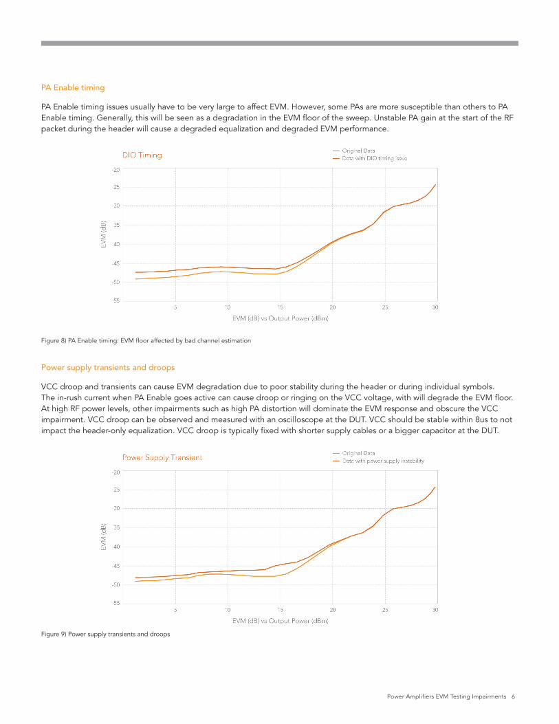
PA Enable timing
PA Enable timing issues usually have to be very large to affect EVM. However, some PAs are more susceptible than others to PA Enable timing. Generally, this will be seen as a degradation in the EVM floor of the sweep. Unstable PA gain at the start of the RF packet during the header will cause a degraded equalization and degraded EVM performance.
Figure 8) PA Enable timing: EVM floor affected by bad channel estimation
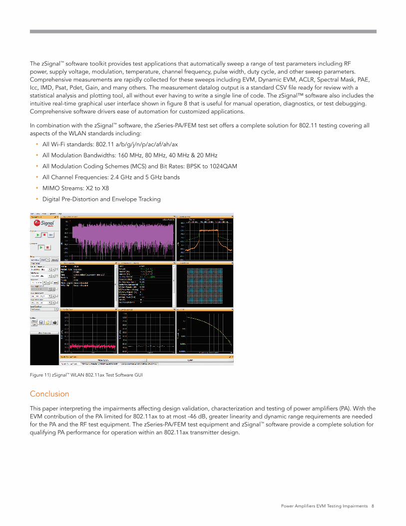
Power supply transients and droops
VCC droop and transients can cause EVM degradation due to poor stability during the header or during individual symbols. The in-rush current when PA Enable goes active can cause droop or ringing on the VCC voltage, with will degrade the EVM floor. At high RF power levels, other impairments such as high PA distortion will dominate the EVM response and obscure the VCC impairment. VCC droop can be observed and measured with an oscilloscope at the DUT. VCC should be stable within 8us to not impact the header-only equalization. VCC droop is typically fixed with shorter supply cables or a bigger capacitor at the DUT.
Figure 9) Power supply transients and droops

Power Amplifiers EVM Testing Impairments 7
802.11ax PA Test Equipment
For previous generations of 802.11 Wi-Fi, PA test results were not as susceptible to minor impairments and test system errors. Correlation and golden-DUT testing may have been adequate in some test scenarios. Going forward, in order to demonstrate the requisite EVM performance for 802.11ax 1024QAM, test system error sources must be minimized. The entire integrated test system must be optimized to mimic the real world operating conditions and performance of the PA.
802.11ax requires additional functionality and performance within the test equipment used for design validation, characterization and testing of power amplifiers. Within the RF instruments, the noise floor, phase noise, intermodulation distortion, and in-band spurious signals must be optimized to avoid degradation of the loopback residual EVM floor. Note that the 4X narrower subcarrier spacing of 802.11ax magnifies the phase noise error contribution of the test equipment. In addition, the other instruments must be selected and integrated to deliver the correct performance and functionality as to not impair the measured PA performance. This includes the DC power supplies, analog and digital instruments.
Figure 9 shows a block diagram of a typical test setup for PA testing using the LitePoint zSeries-PA/FEM test solution, including:
• z8653 6 GHz Vector Signal Analyzer (VSA), 1 GHz analysis bandwidth
• z8751 6 GHz Vector Signal Generator (VSG), 500 MHz modulation bandwidth
• z8801 8 GHz Local Oscillator Synthesizer (qty. 2), Low Phase Noise option for VSA and VSG
• z5211 200MS/s Arbitrary Waveform Generator
• z471 Source Measure Unit (SMU) including cabling with transient compensation circuitry
• PXIe chassis & host computer
Figure 10) Test equipment block diagram for PA testing
The zSeries-PA/FEM Test Solution shown in figure 7 is comprised of a 6 GHz VSG/VSA combination with measurement bandwidths up to 1 GHz. In addition to wide measurement bandwidth that is useful for digital pre-distortion testing, the zSeries test solution provides the low noise and distortion necessary for characterization and testing of 802.11ax devices. The zSeries test solution provides an exceptional loop-back residual EVM floor better than -50 dB for 80MHz 802.11ax (header-only equalization). Other instruments are completely integrated to provide a comprehensive out-of-the-box solution with the functionality and performance necessary for 802.11ax PA testing.
PA Enable Vcc
SourceMeasure
Unit(SMU)
ArbitraryWave
Generator
SignalConditioner
VectorSignal
Generator
500 MHzMbd BW +27 dbmCW 1 GHzIF BW
VectorSignal
AnalyzerDUT Loss (dB)Loss (dB)
Power Amplifiers EVM Testing Impairments 8
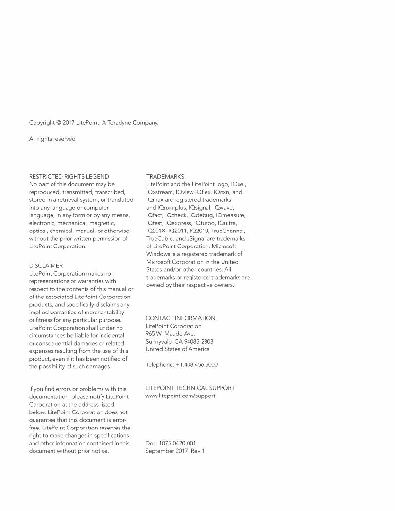
The zSignal™ software toolkit provides test applications that automatically sweep a range of test parameters including RF power, supply voltage, modulation, temperature, channel frequency, pulse width, duty cycle, and other sweep parameters. Comprehensive measurements are rapidly collected for these sweeps including EVM, Dynamic EVM, ACLR, Spectral Mask, PAE, Icc, IMD, Psat, Pdet, Gain, and many others. The measurement datalog output is a standard CSV file ready for review with a statistical analysis and plotting tool, all without ever having to write a single line of code. The zSignal™ software also includes the intuitive real-time graphical user interface shown in figure 8 that is useful for manual operation, diagnostics, or test debugging. Comprehensive software drivers ease of automation for customized applications.
In combination with the zSignal™ software, the zSeries-PA/FEM test set offers a complete solution for 802.11 testing covering all aspects of the WLAN standards including:
• All Wi-Fi standards: 802.11 a/b/g/j/n/p/ac/af/ah/ax
• All Modulation Bandwidths: 160 MHz, 80 MHz, 40 MHz & 20 MHz
• All Modulation Coding Schemes (MCS) and Bit Rates: BPSK to 1024QAM
• All Channel Frequencies: 2.4 GHz and 5 GHz bands
• MIMO Streams: X2 to X8
• Digital Pre-Distortion and Envelope Tracking
Figure 11) zSignal™ WLAN 802.11ax Test Software GUI
Conclusion
This paper interpreting the impairments affecting design validation, characterization and testing of power amplifiers (PA). With the EVM contribution of the PA limited for 802.11ax to at most -46 dB, greater linearity and dynamic range requirements are needed for the PA and the RF test equipment. The zSeries-PA/FEM test equipment and zSignal™ software provide a complete solution for qualifying PA performance for operation within an 802.11ax transmitter design.

Power Amplifiers EVM Testing Impairments 9
Copyright © 2017 LitePoint, A Teradyne Company.
All rights reserved
RESTRICTED RIGHTS LEGENDNo part of this document may bereproduced, transmitted, transcribed,stored in a retrieval system, or translated into any language or computer language, in any form or by any means, electronic, mechanical, magnetic, optical, chemical, manual, or otherwise, without the prior written permission of LitePoint Corporation.
DISCLAIMERLitePoint Corporation makes norepresentations or warranties withrespect to the contents of this manual or of the associated LitePoint Corporation products, and specifically disclaims any implied warranties of merchantability or fitness for any particular purpose. LitePoint Corporation shall under nocircumstances be liable for incidentalor consequential damages or relatedexpenses resulting from the use of thisproduct, even if it has been notified ofthe possibility of such damages.
If you find errors or problems with thisdocumentation, please notify LitePointCorporation at the address listedbelow. LitePoint Corporation does notguarantee that this document is error-free. LitePoint Corporation reserves theright to make changes in specificationsand other information contained in thisdocument without prior notice.
CONTACT INFORMATIONLitePoint Corporation965 W. Maude Ave.Sunnyvale, CA 94085-2803United States of America Telephone: +1.408.456.5000
LITEPOINT TECHNICAL SUPPORTwww.litepoint.com/support
Doc: 1075-0420-001 September 2017 Rev 1
TRADEMARKSLitePoint and the LitePoint logo, IQxel, IQxstream, IQview IQflex, IQnxn, and IQmax are registered trademarks and IQnxn-plus, IQsignal, IQwave, IQfact, IQcheck, IQdebug, IQmeasure, IQtest, IQexpress, IQturbo, IQultra, IQ201X, IQ2011, IQ2010, TrueChannel, TrueCable, and zSignal are trademarks of LitePoint Corporation. Microsoft Windows is a registered trademark of Microsoft Corporation in the United States and/or other countries. All trademarks or registered trademarks are owned by their respective owners.


![OFDM error floor based EVM estimation Error Floor Based EVM Estimation.pdfAWGN source producing the same BER (and EVM) degradation. [1]: The resulting EVM(BER) curves were verified](https://static.fdocuments.in/doc/165x107/5f2e7bc463c3260b31328bb2/ofdm-error-floor-based-evm-estimation-error-floor-based-evm-awgn-source-producing.jpg)