PowderTechnology … · · 2017-08-16where 1/R∗ =1/Rp +1/Rq,1/m ... jn ≈...
11
Powder Technology 321 (2017) 94–104 Contents lists available at ScienceDirect Powder Technology journal homepage: www.elsevier.com/locate/powtec Optimisation of blade type spreaders for powder bed preparation in Additive Manufacturing using DEM simulations S. Haeri Department of Mechanical and Aerospace Engineering, University of Strathclyde, Glasgow G1 1XJ, UK ARTICLE INFO Article history: Received 6 May 2017 Received in revised form 24 July 2017 Accepted 6 August 2017 Available online 9 August 2017 Keywords: Powder Bed Fusion Additive Manufacturing Discrete Element Method Non-spherical particles Multi-sphere approximation Laser Sintering ABSTRACT Powders used in the Particle Bed Fusion process are spread onto compact layers and are then fused to gen- erate a layer of the final part. This process is repeated layer-upon-layer to form the final product. It has recently been demonstrated (Haeri et al., 2017) that spreading the particles with a counter-rotating roller produces a bed with a higher quality (i.e. a lower void fraction) compared to a blade type spreader. This is related to the geometry of the two spreaders which directly changes the bed-spreader contact dynamic and consequently affects the bed’s quality. Based on this rationale, here, it is postulated that changing the blade profile at the blade bed contact region can significantly enhance the bed’s quality and improve the effec- tiveness of a blade as a spreading device. A set of Discrete Element Method (DEM) simulations is performed at device-scale to optimise the geometry of blade spreaders to yield the lowest void fraction using simple rod-shaped grains to control the computational costs. The blade profile is parametrised using a super-ellipse with three geometrical parameters. Firstly, it is demonstrated that geometric optimisation of a blade profile is an effective alternative to using more complex spreading devices. Secondly, for the proposed parametri- sation, the optimum values are found using computer simulations and it is shown that bed volume fractions close to critical values are achievable. Finally, a new technique for multi-sphere approximation (MSA) is developed and applied to 3D models of real powder grains to generate realistic particle shapes for the DEM simulations. Then using these grains it is shown that the proposed optimum blade profile is capable of pro- ducing a bed with qualities comparable (and even better) to a roller at the actual operating conditions and with realistic grain characteristics. © 2017 The Authors. Published by Elsevier B.V. This is an open access article under the CC BY license (http://creativecommons.org/licenses/by/4.0/). 1. Introduction Powder Bed Fusion (PBF) is a promising Additive Manufacturing (AM) technology where polymeric or metallic particles, heated to just below their melting temperature are spread on a fabrication pis- ton to form a thin powder bed (typically in the order of 0.1 mm) using a counter-rotating roller or a blade. Different technologies may then be used to fuse the material powder (see Fig. 1). For example, in a Laser Sintering (LS) process, a laser beam is used to fuse the powder grains. After this stage, the fabrication piston lowers the part slightly and a new layer of powder is applied. The process is repeated until the product is fabricated [1]. According to Gibson and Shi [2] one of the major parameters affecting the properties of manufactured parts by PBF is the mate- rial’s behaviour and its characteristics during the processing while in E-mail address: [email protected]. a powder state. There are several studies focusing on effects of pow- der properties on the quality of parts. Shi et al. [3] suggested that the particle sizes between 75 and 100 l m are most suitable for PBF and in particular for Laser Sintering. Later, Goodridge et al. [4] suggested that parts made with a mixture of particle sizes have greater flexu- ral strength due to a higher solid volume fraction (0 s ). The powder size distribution in relation to the laser power has also been investi- gated. For example, Hao et al. [5] suggest using higher laser energies for smaller particle sizes up to 50 l m. More recently, Ziegelmeier et al. [6] focused on understanding the bulk and flow behaviour of polymer powders in relation to the properties of produced parts in LS. They mainly concluded that the tensile strength and elongation at break are enhanced by increas- ing 0 s . In addition, they examined the powder bed surface roughness and showed that at higher values, the part’s surface roughness also increases. Berretta et al. [7] investigated the effects of particle char- acteristics (both grain and bulk), such as the size distribution, angle of repose, flowability and morphology on the quality of parts for poly ether ether ketone (PEEK) powder. http://dx.doi.org/10.1016/j.powtec.2017.08.011 0032-5910/© 2017 The Authors. Published by Elsevier B.V. This is an open access article under the CC BY license (http://creativecommons.org/licenses/by/4.0/).
-
Upload
phungxuyen -
Category
Documents
-
view
215 -
download
2
Transcript of PowderTechnology … · · 2017-08-16where 1/R∗ =1/Rp +1/Rq,1/m ... jn ≈...
Powder Technology 321 (2017) 94–104
Contents lists available at ScienceDirect
Powder Technology
j ourna l homepage: www.e lsev ie r .com/ locate /powtec
Optimisation of blade type spreaders for powder bed preparation inAdditive Manufacturing using DEM simulations
S. HaeriDepartment of Mechanical and Aerospace Engineering, University of Strathclyde, Glasgow G1 1XJ, UK
A R T I C L E I N F O
Article history:Received 6 May 2017Received in revised form 24 July 2017Accepted 6 August 2017Available online 9 August 2017
Keywords:Powder Bed FusionAdditive ManufacturingDiscrete Element MethodNon-spherical particlesMulti-sphere approximationLaser Sintering
A B S T R A C T
Powders used in the Particle Bed Fusion process are spread onto compact layers and are then fused to gen-erate a layer of the final part. This process is repeated layer-upon-layer to form the final product. It hasrecently been demonstrated (Haeri et al., 2017) that spreading the particles with a counter-rotating rollerproduces a bed with a higher quality (i.e. a lower void fraction) compared to a blade type spreader. This isrelated to the geometry of the two spreaders which directly changes the bed-spreader contact dynamic andconsequently affects the bed’s quality. Based on this rationale, here, it is postulated that changing the bladeprofile at the blade bed contact region can significantly enhance the bed’s quality and improve the effec-tiveness of a blade as a spreading device. A set of Discrete Element Method (DEM) simulations is performedat device-scale to optimise the geometry of blade spreaders to yield the lowest void fraction using simplerod-shaped grains to control the computational costs. The blade profile is parametrised using a super-ellipsewith three geometrical parameters. Firstly, it is demonstrated that geometric optimisation of a blade profileis an effective alternative to using more complex spreading devices. Secondly, for the proposed parametri-sation, the optimum values are found using computer simulations and it is shown that bed volume fractionsclose to critical values are achievable. Finally, a new technique for multi-sphere approximation (MSA) isdeveloped and applied to 3D models of real powder grains to generate realistic particle shapes for the DEMsimulations. Then using these grains it is shown that the proposed optimum blade profile is capable of pro-ducing a bed with qualities comparable (and even better) to a roller at the actual operating conditions andwith realistic grain characteristics.
© 2017 The Authors. Published by Elsevier B.V. This is an open access article under the CC BY license(http://creativecommons.org/licenses/by/4.0/).
1. Introduction
Powder Bed Fusion (PBF) is a promising Additive Manufacturing(AM) technology where polymeric or metallic particles, heated tojust below their melting temperature are spread on a fabrication pis-ton to form a thin powder bed (typically in the order of 0.1 mm) usinga counter-rotating roller or a blade. Different technologies may thenbe used to fuse the material powder (see Fig. 1). For example, in aLaser Sintering (LS) process, a laser beam is used to fuse the powdergrains. After this stage, the fabrication piston lowers the part slightlyand a new layer of powder is applied. The process is repeated untilthe product is fabricated [1].
According to Gibson and Shi [2] one of the major parametersaffecting the properties of manufactured parts by PBF is the mate-rial’s behaviour and its characteristics during the processing while in
E-mail address: [email protected].
a powder state. There are several studies focusing on effects of pow-der properties on the quality of parts. Shi et al. [3] suggested that theparticle sizes between 75 and 100 lm are most suitable for PBF andin particular for Laser Sintering. Later, Goodridge et al. [4] suggestedthat parts made with a mixture of particle sizes have greater flexu-ral strength due to a higher solid volume fraction (0s). The powdersize distribution in relation to the laser power has also been investi-gated. For example, Hao et al. [5] suggest using higher laser energiesfor smaller particle sizes up to 50 lm.
More recently, Ziegelmeier et al. [6] focused on understandingthe bulk and flow behaviour of polymer powders in relation to theproperties of produced parts in LS. They mainly concluded that thetensile strength and elongation at break are enhanced by increas-ing 0s. In addition, they examined the powder bed surface roughnessand showed that at higher values, the part’s surface roughness alsoincreases. Berretta et al. [7] investigated the effects of particle char-acteristics (both grain and bulk), such as the size distribution, angleof repose, flowability and morphology on the quality of parts for polyether ether ketone (PEEK) powder.
http://dx.doi.org/10.1016/j.powtec.2017.08.0110032-5910/© 2017 The Authors. Published by Elsevier B.V. This is an open access article under the CC BY license (http://creativecommons.org/licenses/by/4.0/).
S. Haeri / Powder Technology 321 (2017) 94–104 95
Undoubtedly, the characteristics of individual particles have asignificant effect on the success of PBF processes. Therefore, thisfact cannot be ignored in any numerical technique used for design,prediction and understanding of PBF processes. The Discrete ElementMethod (DEM) is a particle based approach relying only on the firstprinciples and is receiving significant attention recently for simula-tion of such systems. This is due to the capability of DEM to directlyinclude the effects of grain characteristics such as material proper-ties, size distribution and morphology. DEM was first proposed inlate 1970s [8] and there is a large body of research on the method ingeomechanics literature (see [9] for a modern introduction).
Application of DEM to PBF was pioneered by Zohdi [10–12] withregard to the development of laser heat sources and particle sin-tering models. Parteli and Pöschel [13] performed DEM simulationsof the powder spreading process and found that the larger transla-tional velocity of the roller and broader particle size distribution leadto a larger surface roughness. Xiang et al. [14], simplified the pro-cess by considering an assembly of 4000 particles undergoing threeprocesses in their DEM simulations: random packing, layering andcompression. They showed that the solid volume fraction increasesby increasing the layer thickness. Steuben et al. [15] also proposed anew framework for modelling the full process including a laser heatsource and powder sintering.
Haeri et al. [1] on the other hand provided DEM simulation ofspreading process at device scales and used high 0s and layer’s surfaceroughness 4 values as a measure of a successful powder spreadingprocess (i.e. a high-quality bed). This is known to be directly corre-lated with the quality of final parts [6]. In their extensive parametricstudies, Haeri et al. [1] investigated the effects of spreader type, itstranslational velocity, particle shape (and its distribution) and layerthickness on the bed quality. They parametrised elongated parti-cles using their aspect ratios Ar and showed that the highest 0s canbe achieved at Ar = 1.5. They also analysed the micro-structuresof elongated particles to explain the relation between various pro-cess parameters and the bed quality. They investigated two differenttypes of spreading devices: rollers and blades. The consensus in thecommunity is that the rollers generally produce higher quality pow-der beds which was confirmed in this study. Haeri et al. [1] however,related this to a particle dragging phenomenon and a small contactarea between a blade spreader and the bed.
In this paper, it is postulated that since a low-quality bed gen-erated using a blade is essentially a result of its geometry – as wassuggested in [1] – it can be rectified purely by geometric modificationof the blade. Therefore, a new class of blades is proposed with a mod-ified head profile. The suggested profile is a supper-ellipse with threeadjustable parameters. It is shown that simple geometrical modifica-tions can significantly affect the bed quality and then using a seriesof computer simulations the best values for the these parameters areidentified and reported. The optimised profile is then compared witha roller type spreader at different operating conditions and for real-istic particle shapes. The powder grains are approximated using anew multi-sphere approximation (MSA) technique which will be dis-cussed in detail. It is then shown that the optimised profile is capableof generating a powder bed with qualities (in terms of 0s) on par withthose generated using a roller at different operating conditions andwith realistic grain shapes. This could greatly reduce the productionand maintenance costs of the PBF devices by obviating the need forsignificantly more expensive and complex spreading devices.
2. Methodology
2.1. Discrete Element Method
The Large-scale atomic/molecular massively parallel simulator(LAMMPS) code [16] is used for all the DEM simulations. A linearHookean spring-dashpot contact force model is applied to each pair
Fig. 1. Schematic presentation of the Laser Sintering process.
of particles p and q whenever the two particles overlap, i.e. whendpq = Rp + Rq − rpq > 0, where rpq =‖rp −rq‖, and ‖ •‖ represents theEuclidean norm (magnitude) of any vector. In addition, Rk, k ∈ {p, q},is the radius of the kth spheroid and rk is the position vector ofits centre of mass (CoM). The normal and tangential components ofspring-dashpot force are given by
Fn = jndpqnpq − cnm∗vnpq (1)
Ft = −jtutpq − ctm∗vt
pq, (2)
where jn,cn, jt and ct are spring elastic and damping constants innormal and tangential directions respectively. In addition, vn
pq andvt
pq are relative normal and tangential velocities. The effective massis defined as m∗ = mpmq/(mp + mq) where mk, k ∈ {p, q}, is themass of kth particle. The unit normal vector in the direction of theline connecting a pair of spheroid centres is presented by npq andelastic shear displacement by ut
pq. The tangential force is limited to∥∥∥Ftpq
∥∥∥ ≤ lc
∥∥∥Fnpq
∥∥∥ where lc is the Coulomb friction coefficient which is
set to 0.5 in this study [1] considering the angle of repose test resultsfor different PEEK powders reported by Wang et al. [17]. Similarly, anormal Fn
pw and a tangential force Ftpw are defined between particle p
and the bottom wall w.Shape effects are considered in this paper and hence, a ver-
satile multi-sphere technique is used [1]. The DEM, as describedabove, is formulated for sphere-sphere collisions. In the multi-sphere approach, the contacts are still detected between spherepairs. However, instead of integrating the Newton’s laws of motionfor each sphere, a total force and torque around the CoM of eachnon-spherical particle is calculated by adding-up individual contactforces of its constituent spheres. The CoM position of each rod isthen updated using Newton’s laws of motion and the location ofindividual spheres is updated assuming rigid-body dynamics.
In this paper, initially rod-shaped particles are considered whichcan be parametrised using an aspect ratio Ar. This is chosen sinceelongated particles with a similar aspect ratio distribution and roundedges can be considered as crude approximations to a populationof impact-milled PEEK particles [1]. In addition, rod-shaped parti-cles with required aspect ratios of Ar = 1.5, 2.0, and 2.5 could begenerated with 2, 3 and 4 spheroids, considerably reducing the com-putational costs. Therefore, these are used as crude approximations
96 S. Haeri / Powder Technology 321 (2017) 94–104
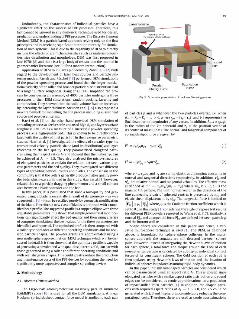
Fig. 2. The device simulation set-up and initial preparations presented for a modified blade profile. (a) The initial bed preparation using a rain fall technique is presented; particlesare coloured with their velocity magnitudes and diameters are not to scale for better presentation. (b) The rod-shaped particles with different aspect ratios Ar are presented usinga multi-sphere approach. Also, the particles are coloured in a representative simulation with vy (velocity in y-direction). Only a section of the spreader with a width Lx is simulatedby choosing periodic boundary conditions in x-direction and in y-direction neutral walls are used (no interaction with particles).
to the real particles, for the first stage of optimisation where a largenumber of simulations is required.
An initial assembly of particles (before the spreading) is createdusing a rainfall technique (Fig. 2a). Also, the simulation set-up isdepicted in Fig. 2b. The bottom boundary is a rigid wall that exerts anormal and a tangential force on the particles (equivalent to assum-ing an infinity large sphere in Eqs. (1) and (2)). To prevent unboundedrotation of particles on the bottom wall, a rolling friction modelis implemented. The adopted model constantly applies a resistivetorque to the particles in contact with the bottom wall, which isgiven by [18–20]
Tpw = −lrRp
∥∥∥Fnpw
∥∥∥ yrel∥∥yrel∥∥ . (3)
In Eq. (3) yreli is the relative angular velocity between particle p
and the bottom wall w and lr = 0.005 is used for all the simulationsbased on the analysis of Zhou et al. [18] and Haeri et al. [1]. The elasticspring constant jn, in Eq. (1) is set according to [21]
jn =1615
√R∗Y∗
(15m∗V2
c
16√
R∗Y∗
) 15
, (4)
and the dash-pot constant is calculated as
cn =
√4jn(ln E)2
m∗ [p2 + (ln E)2
] , (5)
where 1/R∗ = 1/Rp + 1/Rq, 1/m∗ = 1/mp + 1/mq, 1/Y∗ =(1 − m2
p
)/Yp +
(1 − m2
q
)/Yq. In addition, Y, E, m and Vc are the Young’s
modulus, coefficient of restitution, Poisson ratio and a characteris-tic velocity respectively. The coefficient of restitution is set to 0.5.The values of Young’s modulus and Poisson ratio are set to 3.7 GPaand 0.4 for all particles which are typical values for PEEK polymeric
particles [22]. Assuming Vc = VTblade
(or VT
spreader
), Eq. (4), yields
jn ≈ 1500N/m depending on the roller velocity. Therefore, a con-stant value of jn = 1500 is adopted for all the simulations. Thetangential force constants jt and ct are respectively set to 2/7jn and1/2cn (see Shäfer et al. [23] for details).
The spring-dashpot model is chosen in this study due to its lowcomputational costs. Despite the simplicity of the model, Di Renzoand Di Maio [21] showed that if the parameters of the model areaccurately chosen, the model performs as well as the full Hertz-Mindlin and Deresiewicz model – and better than the simplerversions of this model – as long as the details of collision forcesare not relevant (for example in particle breakage). It is also worthmentioning that, absolute values for the parameters measured inthis paper may vary depending on the powder physical properties,shape and size distribution among other factors. Nevertheless, thenew designs are expected to remain effective for metallic/polymericpowders used in AM. In this study the blade design to maximise vol-ume fraction is of interest and the trends are used to guide the design.Therefore, absolute values – which will be affected by the aforemen-tioned factors – have no impact on the validity of the conclusiondrawn here.

S. Haeri / Powder Technology 321 (2017) 94–104 97
Table 1A summary of simulation and post-processing parameters with a short description.This is provided for reference only and the parameters are explained in detail in thetext. In addition, all the dimensional parameters are reported in SI units.
Parameter Description Value
m∗ Effective mass for particles“p” and “q”
m∗ = mpmqmp+mq
jn Normal spring constant [1] 1500E Coefficient of restitution 0.5lc Coulomb friction coefficient 0.5
cn Normal dash-pot constant√
4jn(ln E)2
m∗[p2+(ln E)2]
jt Tangential springconstant [23]
2/7jn
ct Tangential dash-potconstant [23]
1/2cn
lr Rolling friction constantHaeri et al. [1]
0.005
Dsph Sphere diameter (for rods) 10−4
qrod Particle density (PEEK) 1300� Sphere overlap 0.5DsphtextAr Aspect ratio ∈ {1.0, 1.5, 2.0, 2.5}Lx , Ly , Lz Domain size in x, y, z 2.46 × 10⁻³, 0.04, 0.03dinit Layer thickness (before
spreading)10Dsph
dspreader Spreader’s displacement 5Dsph
as Spreader profile thicknessparameter
(10, 25, 100)Dsph
bs Spreader profile hightparameter
(10, 20, 50)Dsph
ns Spreader profile shapeparameter
(0.5, 1.0, 1.5, 2.0, 5.0)
2.2. Simulation set-up and post-processing
The rods with various aspect ratios Ar = 1.5, 2.0, 2.5 are cre-ated by overlapping spheres with an overlap of � = 0.5Dsph (Fig. 2b)and number densities of NAr = 0.5, 0.3, 0.2 respectively. The initialconfiguration (before the spreading starts) is prepared by pouringrandomly generated particles on the bottom wall (see Fig. 2a). Thisis done within a simulation box with dimensions Lx = 2.46 × 10⁻³,Ly = 0.04 and Lz = 0.03. The geometric parameters Lx, Ly and Lz
are the width, length and height of the simulation box (red bound-aries in Fig. 2b). Note that all values are in SI units except otherwisestated. The preparation method is different from the delivery systemin LS devices; nevertheless, since the powder is not compacted inthe delivery piston and rests under its natural weight, this method ofinitiating the simulation, is adequate for the current purpose.
The box size in the flow-direction Ly changes to accommodate allthe particles as they are spread and the corresponding walls exertno force on the particles (walls labelled neutral in Fig. 2b). The num-ber of particles in each simulation is adjusted to supply an initialthickness of dinit ≈ 10Dsph for all particle types, where Dsph is thediameter of spheres used to generate the rod-shaped particles. Inaddition, the blade displacement from the bottom wall, dblade is setto 5Dsph which is the profile’s minimum distance to the bottom walland essentially sets the powder bed thickness. Table 1 summarisesall the parameters used in this study.
The solid volume fraction, 0s, is calculated and its maximum valueis used as the objective function – which means a more effectivespreading process – to optimise the blade profile. The 0s values arecalculated using a Voronoi tessellation technique [24] and only asection of the bed away from the edges are considered to suppressesthe end effects; this is achieved by only including the particles in thecalculations that fit within the bounding box away from both endsand the bed’s surface. The details of choosing this box, in addition tosensitivity of the results on this choice are discussed in great detailsin Haeri et al. [1]. This is, in fact, a reasonable assumption since thefull extent of the bed in not normally used for fabrication.
3. The new blade design
Haeri et al. [1] argued that an “effective” bed-spreader contact,determines the quality of a prepared powder bed (a high 0s andlow 4). Based on visualisations of the bed-spreader contact dynamicsthey related this to a particle dragging phenomenon which distortsthe bed if a spreader type did not provide an effective support forthe particle heap that forms in front of the spreader (see Fig. 2b).This suggests that a geometric modification of the spreader should inprinciple, significantly improve the bed’s quality.
Fig. 3. Different spreader profiles used for the optimisation. Only a subset of all designs are presented to show the effects of changing parameters as , bs and ns . Only half of thewidest blade with as = 100Dsph is presented.

98 S. Haeri / Powder Technology 321 (2017) 94–104
Fig. 4. Simple shear flow simulation of rod-shaped particle assembly with Ar = 1.5, 2.0, 2.5 and number densities NAr = 0.5, 0.3, 0.2. (A) The initial configuration beforecompression to the desired volume fraction. (B) The configuration after homogeneous compression to the desired volume fraction (presented for 0 = 0.57). (C) Sheared assembly.Note that figure (A) is scaled differently compared to (B) and (C). Particles are coloured with their velocity magnitudes.
By modifying the spreader’s head profile a new class of spreadingdevices is suggested. A super-elliptic profile with three parametersns, as and bs is proposed here:
∣∣∣∣ yas
∣∣∣∣ns
+∣∣∣∣ zbs
∣∣∣∣ns
= 1. (6)
The parameters ns, as and bs respectively, control the overallshape, width and height of the profile. The blade thickness is ws =2as and its height is hs � bs. Note that the blade’s height is longerthan bs and remains a straight line for z > bs + dblade, its valueis chosen to be larger than the maximum height of the powderheap formed in front of the blade during the spreading process andhas no effect on the optimisation results. In Fig. 3 various profileshapes proposed for the optimisation are presented. Three values(10, 25, 100)Dsph and (10, 20, 50)Dsph are chosen for as and bs respec-tively. The parameter ns determines the overall shape of the profile.Initially, five different shapes ns ∈ {0.5, 1.0, 1.5, 2.0, 5.0} are consid-ered (see Fig. 3), however, after the initial optimisation a few morevalues are considered to show that the best value identified is in factthe optimum value.
3.1. The particle assembly characteristics
Before starting the main computer experiments, it is necessary toacquire a better insight into the jamming behaviour of an assemblyof particles with a similar distribution of Ar. This will allow to setreasonable objectives for the new blade designs. The critical volumefraction 0c
s – where the jamming transition occurs – is selected asthe objective. To achieve 0s > 0c
s , significant compressive forces arerequired which may be achieved by a subsequent compression. How-ever, this increases the process complications and significantly slowsdown the fabrication and is not a normal practice. Alternatively, itcould be accomplished by reducing the displacement between pre-vious layer and the spreader. This, however, could adversely affectthe volume fraction due to particle jamming [1] particularly for elon-gated particles. Therefore, a volume fraction close to 0c
s seems to bea reasonable expectation.
To understand the jamming behaviour of the assembly consid-ered for computer experiments, see Section 2.2, a set of simple shearflow simulations are performed. For all the simulations an initialassembly is prepared by producing a non-overlapping lattice of Np =
20 × 20 × 20 = 8000 particles, initializing each particle velocity andorientation to a random value – Fig. 4 – followed by homogeneouscompression to the desired volume fraction 0 in a periodic box withLees-Edwards boundary conditions [25]. After, shearing the assem-bly, see Fig. 4, the stress is calculated by adding contributions fromcollision and velocity fluctuations:
s =1V
⎡⎢⎢⎣
Np∑p=1
Np∑q=1q=p
rpqFcpq +
Np∑p=1
mpv′pv′
p
⎤⎥⎥⎦ , (7)
where V is the volume of the simulation box and v′p is the fluctuat-
ing velocity component of pth particle. The pressure – mean normalstress – is then given by P = (s11 + s22 + s33)/3 and the relevantstress component is s12 = sxy. All the collision model parameters
Fig. 5. Determination of the critical volume fraction for the assembly of particlesshown on the figure. Non-dimensional flow curves are presented at various volumefractions and shear rates to identify 0c
s = 0.58.

S. Haeri / Powder Technology 321 (2017) 94–104 99
(a) ns = 0 .5 (b) ns = 1 .0
(c) ns = 1 .5 (d) ns = 2 .0
(e) ns = 5 .0 (f) Optimum ns
Fig. 6. Variations in solid volume fraction 0s with different optimisation parameters. The values on bs axis correspond to (10, 20, 50) × Dsph. In the inset of figure (a), the velocitymagnitude of particles near two blades with ns = 0.5 and 1.5, with as = 25Dsph and bs = 20Dsph are highlighted.
are set to those used for the device scale computer simulations. Itis well established [26,27] that the flow curves (e.g. P vs c, wherec is the shear rate) for dry granular material exhibit a drastic jumpby increasing 0s to values above 0c
s . Therefore, generating a fewflow curves proves to be a convenient and fast technique to iden-tify the 0c
s . Fig. 5 shows the results of 60 simulations. In this figureP∗ = PDeqv/jn versus c∗ = cDeqv/
√jn/(qsDeqv) are presented. Here,
Deqv is defined by∑
iNAr ,iDieqv and Di
eqv is the equivalent diameter ofparticles with an specific Ar ∈ {1.5, 2.0, 2.5}.
Clearly, the critical volume fraction happens between 0s = 0.575and 0s = 0.585. The curve for 0s = 0.580 shows the typical
behaviour very close to the 0cs such as very large fluctuations and
difficult convergence at low c. For c∗ ≥ 4 × 10⁻⁴ the curve for 0cs
continues on the asymptote to the quasi-static and inertial regimes.The erratic behaviour of the curve for c∗ ≤ 4 × 10⁻⁴ is a direct indi-cation of very large variances in the stress calculations which requireextremely long simulation to statistically converge. It is possible tosubdivide the interval between 0s = 0.580 and 0s = 0.585 andrun the simulations for longer to obtain a more accurate estimate.However, the current accuracy is sufficient for our purpose and 0s =0.58 is identified as the critical volume fraction for the assembly ofparticles under consideration.
100 S. Haeri / Powder Technology 321 (2017) 94–104
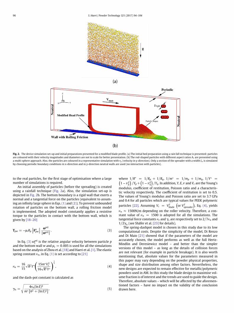
Fig. 7. 3D reconstruction of realistic PEEK particles. Images of the impact-milled particles are extracted from a Scanning Electron Microscope (SEM) image of a sample of thepowder which are presented alongside the corresponding 3D reconstructed stereo-lithography (STL) models. The image data are taken from the publicly available data-set byHaeri [29].
3.2. Optimisation results and discussions
The results of 48 simulations with different optimisation param-eters are presented in Fig. 6. Before analysing the results any further,it is clear that the blade’s geometry is indeed a major parameter forcontrolling the bed quality. Fig. 6 clearly shows the variation in 0sfrom low values of 0s ≈ 0.4 to values as high as 0s ≈ 0.58 close tothe critical volume fraction for elongated particles. This proves theeffectiveness of geometrical modification of the blade’s head profileto maximise 0s and indicates the validity of the initial hypothesis.
For comparison with a straight edge blade, the data from [1]are used. They performed simulations with mono-sized (Ar =1.0 · · · 2.5) particles at similar operating conditions. However, theyshowed that the characteristics of poly-sized beds (with small vari-ation in the aspect ratios) could be approximated by a numberdensity weighted averaging. To find an approximate value for thepoly-sized case considered here, a number density average of themono-sized simulations of [1] is calculated. This can be written by0s =
∑Ni0s(Ar ,i) which yields a value of 0s = 0.4 for straight
edge blade spreader of a mixture of particles with number densi-ties considered in this paper. The effects of overall profile shape aredemonstrated in Fig. 6a–e. In these figures, the value of the parame-ter ns is changed which characterises the overall shape of the profile.A value of ns = 0.5 generates a concave profile and the results arepresented in Fig. 6a. Evidently, this profile does not improve the com-paction significantly, nevertheless, some improvement is observedespecially for the lowest value of blade width of 5Dsph.
A linear profile can be generated by setting ns = 1. The simula-tion results for this profile and different width and height parametersas and bs are presented in Fig. 6b. The bed quality – as expected –is a function of both profile height and also the spreader width.Generally, shorter (smaller bs) and wider (larger as) profiles gener-ate higher volume fractions 0s. The sensitivity of the linear profileto height is higher for wider designs but almost no dependence onheight is observed for narrow designs (as = 5Dsph). It is also inter-esting to note that 0s dependence on as for the concave profile (ns =0.5) is opposite to that of the linear profile and all the other convexprofiles. It is believed that for a concave profile (ns = 0.5) some
particles may get clogged in the hollow region between the blade’shead profile and the bottom surface (or the previous layers).
The region close to the head is highlighted in the inset of Fig. 6a.It is clear that the particle velocities for the presented convex pro-file (ns = 1.5) increase gradually from zero at bed-blade minimumcontact point (i.e. the point on the blade with minimum z) to VT
blade;whereas for the concave profile (ns = 0.5) there is sudden change inthe velocities close to the blade. This indicates the clogging of powdergrains which eventually degrades the bed. This effect is exagger-ated as the hollow region width is increased since more particles are
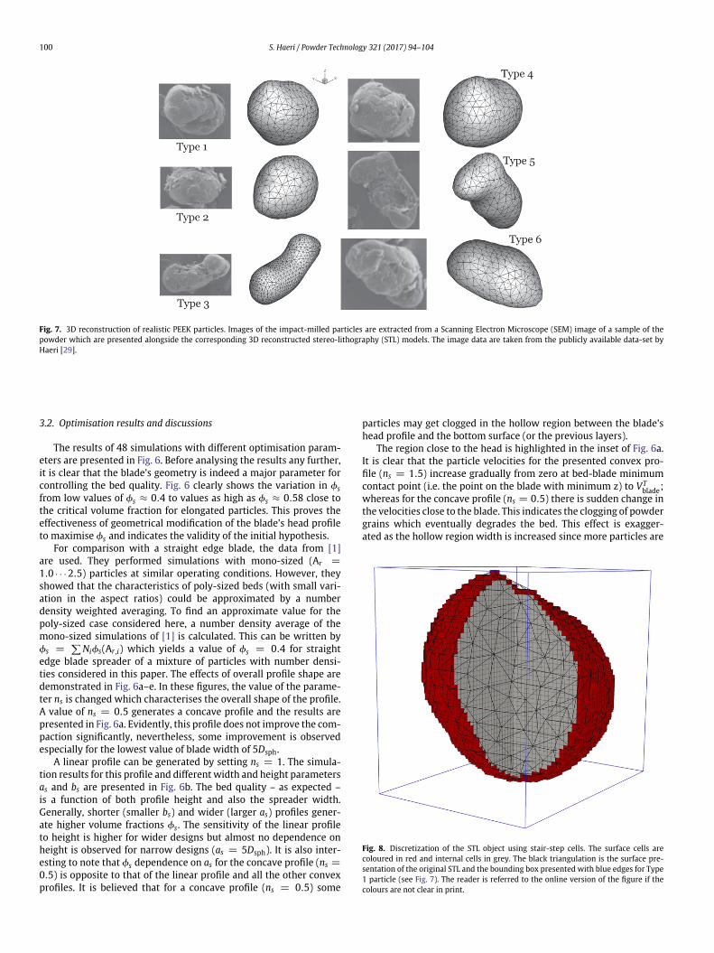
Fig. 8. Discretization of the STL object using stair-step cells. The surface cells arecoloured in red and internal cells in grey. The black triangulation is the surface pre-sentation of the original STL and the bounding box presented with blue edges for Type1 particle (see Fig. 7). The reader is referred to the online version of the figure if thecolours are not clear in print.

S. Haeri / Powder Technology 321 (2017) 94–104 101
Table 2Accuracy of the stair-step discretization of the particle’s STL. The relative error in par-ticle volume is calculated with respect to the analytical value given by Eq. (10). Therelative 2-norm and ∞-norm errors in Ip are calculated with respect to the IMC
p whichis calculated using a standard Monte Carlo integration technique.
Particle type
∣∣∣VSTLp −Vp
∣∣∣VSTL
p× 104
∥∥∥Ip−IMCp
∥∥∥2∥∥∥IMC
p
∥∥∥2
× 103
∥∥∥Ip−IMCp
∥∥∥∞∥∥∥IMCp
∥∥∥∞× 103
1 0.7133 2.8821 3.99832 8.7765 5.3901 6.64753 14.676 2.7746 3.36424 6.3613 4.3804 5.38725 0.8422 2.9625 3.14826 2.0593 0.9668 1.1357
trapped in the larger hollow space. Therefore, wider profiles gener-ate smaller volume fraction for the ns = 0.5 case whereas increasingas improves the quality for all other convex profiles (with ns ≥ 1).
Panels c–e in Fig. 6 show as the value of ns increases from ns = 1.5to ns = 5.0, for all the corresponding values of bs and as the volumefraction increases indicating a better quality. In addition, the sensi-tivity to bs also decreases such that for ns = 5.0 the volume fractionis practically independent of bs. This perhaps is not surprising sincelarger ns values cause a condensation of curvature very close to theedges and the remaining sections of profile away from the edgesare essentially straight lines. Therefore, changing bs does not signifi-cantly change the profile characteristics. For all values of ns ≥ 1 widerprofiles generate beds with larger 0s. The current results show thatoptimisation of the profile is highly successful and 0s for ns = 5.0,as = 100Dsph and bs = 10Dsph approaches a value of 0s = 0.58 closeto 0c
s as identified in the earlier shear flow simulations (see Fig. 5).This is the largest 0s one could expect from the spreading processwithout any subsequent compression.
For the particular powder considered here (with the specifiedmaterial and morphology characteristics) a larger 0s is obviouslynot anticipated and hence further optimisation is redundant. Nev-ertheless, since 0s monotonically increased during the optimisationprocess (see Fig. 6a–e), a valid question is whether 0s versus ns
curve has a plateau and one can choose an arbitrarily large ns, oran optimum ns value actually exists. It is important to note that asn → ∞ the profile will approach a typical rectangular shape whichas demonstrated in [1] significantly degrades the bed quality. There-fore, the existence of an optimum value for ns is certain. To show thatns = 5.0 is in fact that optimum value and generates the highest 0s aseries of the simulations with 3 other values of ns ∈ {7.5, 10.0, 15.0}are performed. The results are presented in Fig. 6f which proves that
ns = 5.0 (noting the resolution of the current parametric study)must be the optimum profile shape.
In this section, the profile with parameters ns = 5.0, as =100Dsph and bs = 10Dsph is identified as the optimum profile. A valueof bs = 10Dsph (=1 mm) may not be feasible to manufacture. How-ever, noting the independence of 0s from bs in Fig. 6e, one can choosea larger value of bs to manufacture a spreader with more realisticphysical dimensions. For the rest of the paper a value of bs = 50Dsphis considered. In this section to control the cost of a large number ofsimulations only rod-shaped powder grains were considered. In thenext section, the new designs will be applied to powder beds withrealistic particle shapes to further demonstrate the effectiveness ofthe new designs compared to a roller.
4. Application to realistic particles
Particle shape is known to have a significant impact on thespreading process [1]. Therefore, in this section to show the effec-tiveness of the proposed design, first, realistic 3D models of PEEKparticles are produced and a versatile minimum sphere packingalgorithm is developed to generate a multi-sphere approximation(MSA) of the real PEEK particles. Then, the quality of a bed generatedusing the new design is compared to a roller-generated bed. It is alsoworth mentioning that impact milled PEEK particles are considereddue to a generally superior roundedness and sphericity compared tothe other production techniques [1]. In this section, an overview ofthe sphere packing approach will be provided and then the resultswill be discussed.
4.1. A new multi-sphere approximation strategy
The strategy used to produce a multi-sphere approximation ofthe real PEEK particles is based on a greedy heuristic (GH) algorithmrecently proposed by Li et al. [28]. There are a few other tech-niques available in the literature, however, the GH algorithm provesto be very versatile and is capable of coping with highly irregularshapes automatically. The original algorithm has been modified andimproved to generate MSAs suitable for large scale DEM simulationswhich will be discussed in this section.
To use a GH technique, first, a 3D representation of the parti-cle’s surface is required. To this end, an image processing algorithmis used to reconstruct 3D grain models from 2D Scanning ElectronMicroscope (SEM) images extracted from [29]. This has been done byadding depth to the image by first generating a “depth map” of theimage followed by symmetric replication. The original SEM imagesare presented alongside the generated 3D stereo-lithography (STL)models in Fig. 7. It is possible to use more sophisticated techniques
Fig. 9. Introduction of a smoothing factor into the new GH algorithm for controlling the number of spheres in the final MSA. The results with three different smoothing factorsare presented. Spheres in the MSAs are coloured based on their diameters D = 2Rca + SFwcell . From left to right NMSA = 732, 26, 11 respectively.

102 S. Haeri / Powder Technology 321 (2017) 94–104
Fig. 10. MSAs generated for particle types 1 · · · 6 with SF = 5. The spheres are presented with a diameter of D = 2Rca + SFwcell .
to generate a 3D model of the grains (e.g. micro-tomography). How-ever, it will be discussed later in this section that one can only hope tocapture the general characteristic of the grains using a multi-sphereapproach since retaining too much surface details will result in anMSA which comprises too many spheres to be feasibly included in alarge scale DEM simulation.
The original GH algorithm starts by producing a discretization ofthe STL model. Li et al. [28] suggested to discretize the STL modelusing a collection of very small spheres (note that this is differ-ent from the final MSA). In this paper, a stair-step discretizationis tested which has successfully been applied to other numericalschemes for fluid-particle interactions such as the fictitious domainmethod [30–33]. This technique has two significant advantages.Firstly, the calculation of volume, mass and moment of inertia willbe trivial after a stair-step discretization since this will fully coverthe entire volume compared to a discretization with spherical cellsas suggested in Li et al. [28]. The volume and moment of inertia canbe written as [32]
Vp =∑�
dv�, (8)
Ip =∑�
qp [(r�• r�)I − r� ⊗ r�] dv�. (9)
The mass is then calculated simply by mp = qpVp. In Eqs. (8) and(9), dv is the volume of the cell and r� is the position vector of �thcell’s centre and ⊗ is the outer product.
The second major advantage is that this could be generated muchquicker than the Li et al.’s [28] discretization approach using spheri-cal cells. One only needs to generate a bounding box for the STL thendecide whether each cell falls within or outside of the STL by shoot-ing a ray in any direction and calculating the number of intersectionbetween the ray and the STL object. An odd number of intersectionsindicates that the cell is inside and even number of intersection indi-cates that the cell is outside the volume. The intersection between
a collection of triangles and a line can be calculated very efficientlyusing the method of Moller and Trumbore [34] and is used here. Thebounding box of each particle is discretized using 50 cells in eachdirection and the internal and surface cells are identified using thedescribed method, see Fig. 8.
To show the accuracy of stair-step discretization, Ip calculatedusing Eq. (9) is compared to the values that are calculated using astandard Monte Carlo (MC) integration technique. The number ofMC samples are increased step-by-step to 106 to ensure a relativeaccuracy of 10−3 for all the integrals. Note that one could use MCin conjunction with spherical cell discretization of [28] but the com-putational costs will be considerably higher. For both stair-step andMC methods one needs to decide whether the cell/sample is withinthe STL or not. Therefore, for example for the current calculation, thecomputational cost of the stair-step approach is only around 12% ofthe MC technique (1.25 × 10⁵ decisions for stair-step method ver-sus 106 for the MC). The Vp values from Eq. (8) are compared directlyto the analytical volume of the STL object calculated using the diver-gence theorem by assuming an arbitrary (subject to ∇ • F = 1) vectorfield F = zez to yield
VSTLp =
∑�
zc�nz
�ds�, (10)
where zc�
is the z-coordinate of a surface element �, nz�
is the z-component of the element’s outward unit normal and ds� is its area.The results of these calculations are summarised in Table 2. Evi-dently, all the relative errors are well below 1% confirming the highaccuracy of the method which is achieved with little computationaleffort.
After identifying the N cells that discretize the STL, Nbnd bound-ary and Nint internal cells (see Fig. 8) are defined such that N =Nint + Nbnd. A set of Nint spheres are then defined on the location ofNint internal cells as candidates to be included in the final MSA. Thedistance between the centre of each candidate and Nbnd boundary
S. Haeri / Powder Technology 321 (2017) 94–104 103
(a) Volume Fraction (b) Surface Roughness
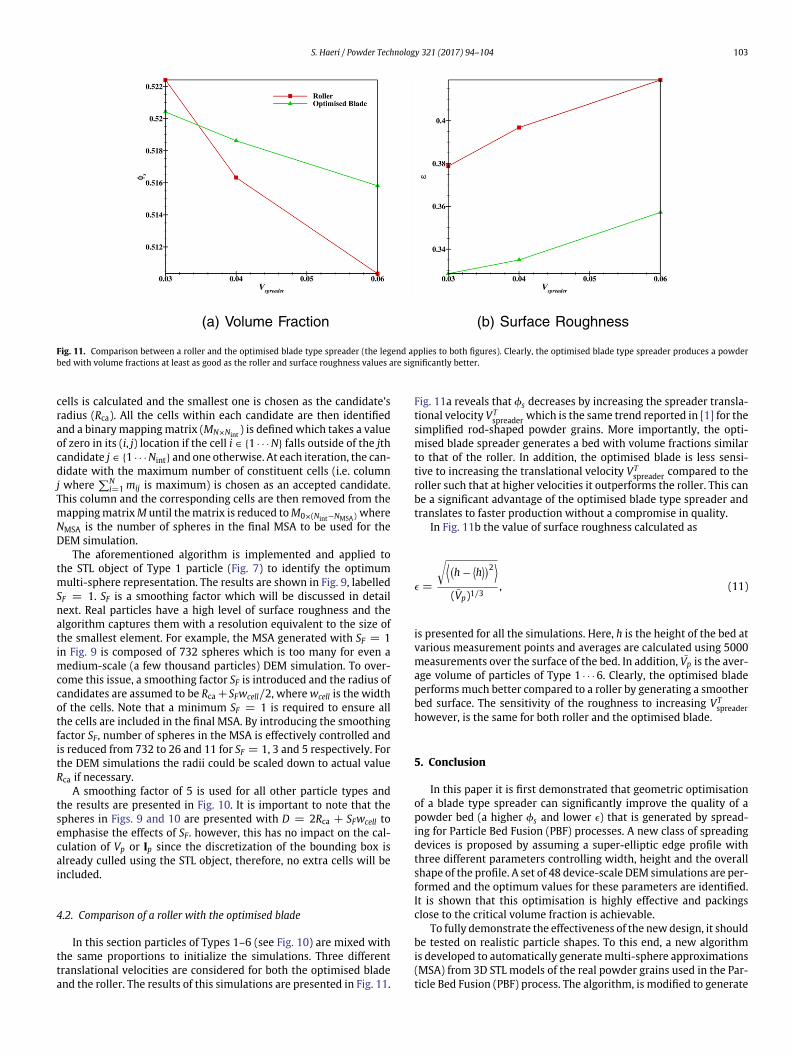
Fig. 11. Comparison between a roller and the optimised blade type spreader (the legend applies to both figures). Clearly, the optimised blade type spreader produces a powderbed with volume fractions at least as good as the roller and surface roughness values are significantly better.
cells is calculated and the smallest one is chosen as the candidate’sradius (Rca). All the cells within each candidate are then identifiedand a binary mapping matrix (MN×Nint
) is defined which takes a valueof zero in its (i, j) location if the cell i ∈ {1 · · · N} falls outside of the jthcandidate j ∈ {1 · · · Nint} and one otherwise. At each iteration, the can-didate with the maximum number of constituent cells (i.e. columnj where
∑Ni=1 mij is maximum) is chosen as an accepted candidate.
This column and the corresponding cells are then removed from themapping matrix M until the matrix is reduced to M0×(Nint−NMSA) whereNMSA is the number of spheres in the final MSA to be used for theDEM simulation.
The aforementioned algorithm is implemented and applied tothe STL object of Type 1 particle (Fig. 7) to identify the optimummulti-sphere representation. The results are shown in Fig. 9, labelledSF = 1. SF is a smoothing factor which will be discussed in detailnext. Real particles have a high level of surface roughness and thealgorithm captures them with a resolution equivalent to the size ofthe smallest element. For example, the MSA generated with SF = 1in Fig. 9 is composed of 732 spheres which is too many for even amedium-scale (a few thousand particles) DEM simulation. To over-come this issue, a smoothing factor SF is introduced and the radius ofcandidates are assumed to be Rca +SFwcell/2, where wcell is the widthof the cells. Note that a minimum SF = 1 is required to ensure allthe cells are included in the final MSA. By introducing the smoothingfactor SF, number of spheres in the MSA is effectively controlled andis reduced from 732 to 26 and 11 for SF = 1, 3 and 5 respectively. Forthe DEM simulations the radii could be scaled down to actual valueRca if necessary.
A smoothing factor of 5 is used for all other particle types andthe results are presented in Fig. 10. It is important to note that thespheres in Figs. 9 and 10 are presented with D = 2Rca + SFwcell toemphasise the effects of SF. however, this has no impact on the cal-culation of Vp or Ip since the discretization of the bounding box isalready culled using the STL object, therefore, no extra cells will beincluded.
4.2. Comparison of a roller with the optimised blade
In this section particles of Types 1–6 (see Fig. 10) are mixed withthe same proportions to initialize the simulations. Three differenttranslational velocities are considered for both the optimised bladeand the roller. The results of this simulations are presented in Fig. 11.
Fig. 11a reveals that 0s decreases by increasing the spreader transla-tional velocity VT
spreader which is the same trend reported in [1] for thesimplified rod-shaped powder grains. More importantly, the opti-mised blade spreader generates a bed with volume fractions similarto that of the roller. In addition, the optimised blade is less sensi-tive to increasing the translational velocity VT
spreader compared to theroller such that at higher velocities it outperforms the roller. This canbe a significant advantage of the optimised blade type spreader andtranslates to faster production without a compromise in quality.
In Fig. 11b the value of surface roughness calculated as
4 =
√⟨(h − ⟨
h⟩)2
⟩(Vp)1/3
, (11)
is presented for all the simulations. Here, h is the height of the bed atvarious measurement points and averages are calculated using 5000measurements over the surface of the bed. In addition, Vp is the aver-age volume of particles of Type 1 · · · 6. Clearly, the optimised bladeperforms much better compared to a roller by generating a smootherbed surface. The sensitivity of the roughness to increasing VT
spreaderhowever, is the same for both roller and the optimised blade.
5. Conclusion
In this paper it is first demonstrated that geometric optimisationof a blade type spreader can significantly improve the quality of apowder bed (a higher 0s and lower 4) that is generated by spread-ing for Particle Bed Fusion (PBF) processes. A new class of spreadingdevices is proposed by assuming a super-elliptic edge profile withthree different parameters controlling width, height and the overallshape of the profile. A set of 48 device-scale DEM simulations are per-formed and the optimum values for these parameters are identified.It is shown that this optimisation is highly effective and packingsclose to the critical volume fraction is achievable.
To fully demonstrate the effectiveness of the new design, it shouldbe tested on realistic particle shapes. To this end, a new algorithmis developed to automatically generate multi-sphere approximations(MSA) from 3D STL models of the real powder grains used in the Par-ticle Bed Fusion (PBF) process. The algorithm, is modified to generate
104 S. Haeri / Powder Technology 321 (2017) 94–104
MSAs suitable for large-scale DEM simulations. The realistic parti-cle shapes are then used to compare the quality of a powder bedprepared by a roller to that generated by the optimised blade.
It is shown that the optimised blade generates a bed with volumefractions very close to the roller. Interestingly, although the opti-mised blade generated a marginally lower volume fraction (0.4%) atthe lowest spreader velocity VT
spreader = 0.03, it is much less sensi-tive to increasing VT
spreader, such that at higher tested velocities thevolume fraction is actually greater (up to 2%) for the blade. This couldbe a significant advantage and means one can increase the veloc-ity (translates to higher production rate) with limited impact on thequality. The surface roughness of the beds generated with both rollerand the blade at different VT
spreader are also compared and the newdesign outperforms the roller for all the tested VT
spreader values.
Acknowledgments
The author gratefully acknowledges the use of ARCHER – The UKNational Supercomputing Service (http://www.archer.ac.uk) – forconducting the simulations under the EPSRC’s Resource AllocationPanel (RAP) Grant E504.
References
[1] S. Haeri, Y. Wang, O. Ghita, J. Sun, Discrete element simulation and experi-mental study of powder spreading process in additive manufacturing, PowderTechnol. 306 (2017) 45–54.
[2] I. Gibson, D. Shi, Material properties and fabrication parameters in selectivelaser sintering process, RTejournal 3: Forum Rapid Technol., 1995.
[3] Y. Shi, Z. Li, H. Sun, S. Huang, F. Zeng, Effect of the properties of the polymermaterials on the quality of selective laser sintering parts, IMechE J. 218 (2004)247–253.
[4] R.D. Goodridge, K.W. Dalgarno, D.J. Wood, Indirect selective laser sinter-ing of an apatite-mullite glass-ceramic for potential use in bone replacementapplications., Proc. Inst. Mech. Eng. H 220 (2006) 57–68.
[5] L. Hao, M.M. Savalani, Y. Zhang, K.E. Tanner, R.A. Harris, Effects of materialmorphology and processing conditions on the characteristics of hydroxyap-atite and high-density polyethylene biocomposites by selective laser sintering,J. Mater: Desi. Applic. 220 (2006) 125–137.
[6] S. Ziegelmeier, P. Christou, F. Wöllecke, C. Tuck, R. Goodridge, R. Hague, E.Krampe, E. Wintermantel, An experimental study into the effects of bulk andflow behaviour of laser sintering polymer powders on resulting part properties,J. Mater. Process. Technol. 215 (2015) 239–250.
[7] S. Berretta, O. Ghita, K. Evans, Morphology of polymeric powders in lasersintering (LS): from polyamide to new peek powders, Eur. Polym. J. 59 (2014)218–229.
[8] P.A. Cundall, O.D.L. Strack, A discrete numerical model for granular assemblies,Geotechnique 29 (1979) 47–65.
[9] E. Onate, D.R.J. Owen, Particle-based Methods: Fundamentals and Applications,Computational Methods in Applied, Springer. 2011.
[10] T.I. Zohdi, Computation of the coupled thermo-optical scattering properties ofrandom particulate systems, Comput. Methods Appl. Mech. Eng. 195 (2006)5813–5830.
[11] T.I. Zohdi, Rapid simulation of laser processing of discrete particulate materials,Arch. Comput. Meth. Eng. 20 (2013) 309–325.
[12] T.I. Zohdi, Additive particle deposition and selective laser processing – acomputational manufacturing framework, Comput. Mech. 54 (2014) 171–191.
[13] E. Parteli, T. Pöschel, Particle-based simulation of powder application inadditive manufacturing, Powder Technol. 288 (2016) 96–102.
[14] Z. Xiang, M. Yin, Z. Deng, X. Mei, G. Yin, Simulation of forming process ofpowder bed for additive manufacturing, J. Manuf. Sci. Eng. 138 (2016) 081002.
[15] J.C. Steuben, A.P. Iliopoulos, J.G. Michopoulos, Discrete element modelingof particle-based additive manufacturing processes, Comput. Methods Appl.Mech. Eng. 305 (2016) 537–561.
[16] S. Plimpton, Fast parallel algorithms for short-range molecular dynamics, J.Comput. Phys. 117 (1995) 1–19.
[17] Y. Wang, D. Rouholamin, R. Davies, O. Ghita, Powder characteristics,microstructure and properties of graphite platelet reinforced poly ether etherketone composites in high temperature laser sintering (HT-LS), Mater. Des. 88(2015) 1310–1320.
[18] Y. Zhou, B. Wright, R. Yang, B. Xu, A. Yu, Rolling friction in the dynamicsimulation of sandpile formation, Physica A 269 (1999) 536–553.
[19] J. Ai, J. Chen, J. Rotter, J. Ooi, Assessment of rolling resistance models indiscrete element simulations, Powder Technol. 206 (2011) 269–282.
[20] C. Wensrich, A. Katterfeld, Rolling friction as a technique for modelling particleshape in DEM, Powder Technol. 217 (2012) 409–417.
[21] A. Di Renzo, F. Di Maio, Comparison of contact-force models for the simula-tion of collisions in DEM-based granular flow codes, Chem. Eng. Sci. 59 (2004)525–541.
[22] A comprehensive review of the materials properties of VICTREX® PEEKTM highperformance polymer, VICTREX, 2016.
[23] J. Shäfer, S. Dippel, D. Wolf, Force schemes in simulations of granularmaterials, J. Phys. I 6 (1996) 5–20.
[24] C.H. Rycroft, Voro++: a three-dimensional Voronoi cell library in C++, Chaos:Interdisciplinary J. Nonlinear Sci. 19 (2009) 041111.
[25] A.W. Lees, S.F. Edwards, The computer study of transport processes underextreme conditions, J. Phys. C 5 (1972) 1921–1928.
[26] S. Chialvo, J. Sun, S. Sundaresan, Bridging the rheology of granular flows inthree regimes, Phys. Rev. E 85 (2012) 023305.
[27] C. Campbell, Elastic granular flows of ellipsoidal particles, Phys. Fluids 23(2011) 013306.
[28] C.-Q. Li, W.-J. Xu, Q.-S. Meng, Multi-sphere approximation of real particlesfor DEM simulation based on a modified greedy heuristic algorithm, PowderTechnol. 286 (2015) 478–487.
[29] S. Haeri, Dataset - discrete element simulation of powder spreading in additivemanufacturing, 2016. http://dx.doi.org/10.15129/c5993a8f-812d-46cf-bef5-92e985d12446.
[30] S. Haeri, J. Shrimpton, On the application of immersed boundary, fictitiousdomain and body-conformal mesh methods to many particle multiphase flows,Int. J. Multiphase Flow 40 (2012) 38–55.
[31] S. Haeri, J.S. Shrimpton, A correlation for the calculation of the local Nus-selt number around circular cylinders in the range 10 ≤ Re ≤ 250 and0.1 ≤ Pr ≤ 40, Int. J. Heat Mass Transf. 59 (2013) 219–229.
[32] S. Haeri, J.S. Shrimpton, A new implicit fictitious domain method for the sim-ulation of flow in complex geometries with heat transfer, J. Comput. Phys. 237(2013) 21.45.
[33] S. Haeri, J.S. Shrimpton, Fully resolved simulation of particle deposition andheat transfer in a differentially heated cavity, Int. J. Heat Fluid Flow 50 (2014)1–15.
[34] T. Moller, B. Trumbore, Fast, minimum storage ray-triangle intersection, J.Graphics Tools 2 (1997) 21–28.


![Jn [PDF Library]](https://static.fdocuments.in/doc/165x107/547d2e2d5906b561378b4656/jn-pdf-library.jpg)