Pour insérer une image : Menu « Insertion / Image » ou ... · OSIRIS MTR FOR MINOR ACTINIDES...
17
DIAMINO EXPERIMENT IN OSIRIS MTR FOR MINOR ACTINIDES RECYCLING PROGRAM NOVEMBER 18 2014 IGORR 2014 | Bariloche| Stéphane BENDOTTI, Cédric NEYROUD, Syriac BEJAOUI 19 NOVEMBRE 2014 | PAGE 1 CEA | 10 AVRIL 2012
Transcript of Pour insérer une image : Menu « Insertion / Image » ou ... · OSIRIS MTR FOR MINOR ACTINIDES...

DIAMINO EXPERIMENT IN
OSIRIS MTR FOR MINOR
ACTINIDES RECYCLING
PROGRAM
NOVEMBER 18 2014
IGORR 2014 | Bariloche| Stéphane BENDOTTI, Cédric NEYROUD, Syriac BEJAOUI
19 NOVEMBRE 2014 | PAGE 1 CEA | 10 AVRIL 2012
Pour insérer une image :
Menu « Insertion / Image »
ou
Cliquer sur l’icône de la zone
image

OUTLINES
Introduction Diamino device description Irradiation environment Device design, neutronic studies Device design, thermal studies First irradiation cycles Other cycles Conclusion
19 NOVEMBRE 2014 | PAGE 2 CEA | November 18 2014
Pour personnaliser le pied
de page et la date :
« Insertion / En-tête et pied
de page »
Personnaliser la zone de de
pied de page
Cliquer sur appliquer partout

INTRODUCTION
19 NOVEMBRE 2014 | PAGE 3 CEA | November 18 2014
Americium recycling in SFR
Transmutation of minor actinides in radial blanket of GEN IV sodium-cooled reactors
Heterogeneous Am-recycling on UO2 matrix for :
But: Low irradiation temperature (from 500 °C to 1500 °C), hight helium production, risk of swelling,
no feedback.
INTRODUCTION
Diamino experiment goal
Behaviour of Americium 241 actinide element only
Two irradiation temperatures (600 °C and 800 °C)
Two burn-up rates
Two microstructures analysis (one with standard density and one with open porosity)
With any batches of post irradiation examination
19 NOVEMBRE 2014 | PAGE 4 CEA | November 18 2014
IRRADIATION ENVIRONMENT
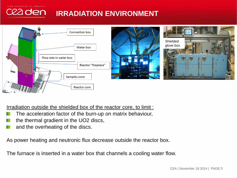
Irradiation outside the shielded box of the reactor core, to limit :
The acceleration factor of the burn-up on matrix behaviour,
the thermal gradient in the UO2 discs,
and the overheating of the discs.
As power heating and neutronic flux decrease outside the reactor box.
The furnace is inserted in a water box that channels a cooling water flow.
19 NOVEMBRE 2014 | PAGE 5 CEA | November 18 2014
Pour insérer une image :
Menu « Insertion / Image »
ou
Cliquer sur l’icône de la zone
image
Shielded
glove box
DIAMINO DEVICE DESCRIPTION
19 NOVEMBRE 2014 | PAGE 6 CEA | November 18 2014
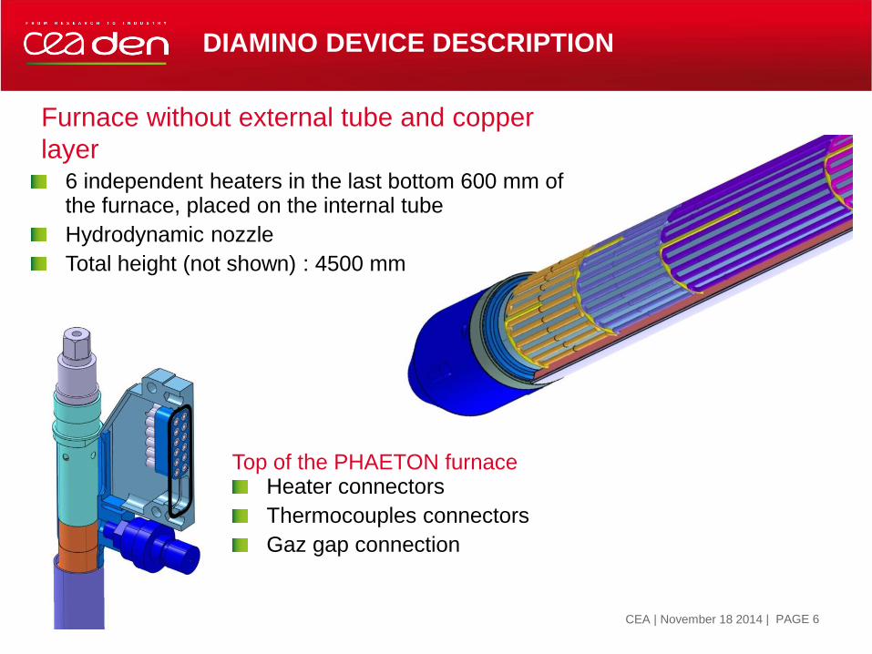
Top of the PHAETON furnace Heater connectors
Thermocouples connectors
Gaz gap connection
Furnace without external tube and copper
layer 6 independent heaters in the last bottom 600 mm of the furnace, placed on the internal tube
Hydrodynamic nozzle
Total height (not shown) : 4500 mm

DIAMINO DEVICE DESCRIPTION
19 NOVEMBRE 2014 | PAGE 7 CEA | November 18 2014
Connector box
Nut for furnace
connection Sealed passage
Bioshield
Fission products filters

DIAMINO DEVICE DESCRIPTION
Loading sample holder UO2 discs placed in TZM cups,
TZM cups sealed in inconel 600 mini-pins
Mini-pins inserted in 2 inconel 600 half shells
Thermocouples inserted in shell grooves
Irradiated zone : ~600 mm height
Total height : 4500 mm
19 NOVEMBRE 2014 | PAGE 8 CEA | November 18 2014
Pour insérer une image :
Menu « Insertion / Image »
ou
Cliquer sur l’icône de la zone
image

DEVICE DESIGN, NEUTRONIC STUDIES
Neutronic calculations allow to determine: Thermal input parameters : gamma heating & initial fissile power (Tripoli-4) and it’s evolution (APOLLO2 2D)
Dosimetric parameters : neutronic flux spectrum and distribution inside the device
Helium rate production, burn-up and period of irradiation, in each fuel disc
Radioprotection input parameters : radio-isotopes inventory evolution (Darwin/Pepin2)
19 NOVEMBRE 2014 | PAGE 9 CEA | November 18 2014
The decrease of the power density during reactor shutdown is real, but linear decrease is due to the lack of data.
Gamma heating evaluations are ~ 25 % upper than measured one.
But transport calculations are not yet validated, a correction of 30% is now applied because delayed neutrons are not computed.
Therefore we prefer to take into account measured values for thermal model.

DEVICE DESIGN, THERMAL STUDIES
The thermal studies allow to : Determine the correction to apply between the sample holder thermocouples to obtain the mean
temperature of the discs in front,
To avoid overheating of the tube of the furnace, the sample holder and all the structures,
To evaluate the regulation capacity of the furnace and the gas mix process,
To optimize the position of the thermocouples to avoid strong gradient fields,
To controle the thermal gradient inside the discs,
19 NOVEMBRE 2014 | PAGE 10 CEA | november 18 2014 LS-Dyna mesh for pre-irradiation studies

DEVICE DESIGN, THERMAL STUDIES
Thermal studies using LS-DYNA,
have been conducted for preliminary
calculations for sensibility at :
Furnace power, time of irradiation,
furnace gases,
to fix the geometrie of gas gaps,
sample holder and mini-pins
materials.
On graph, red pattern peaks show
temperature gradient in the fuel discs.
It increase between the begining (top
graph) and the end (bottom graph) of
irradiation with the fission power.
Pink rectangles give the position and
their relative electrical power.
19 NOVEMBRE 2014 | PAGE 11 CEA | November 18 2014
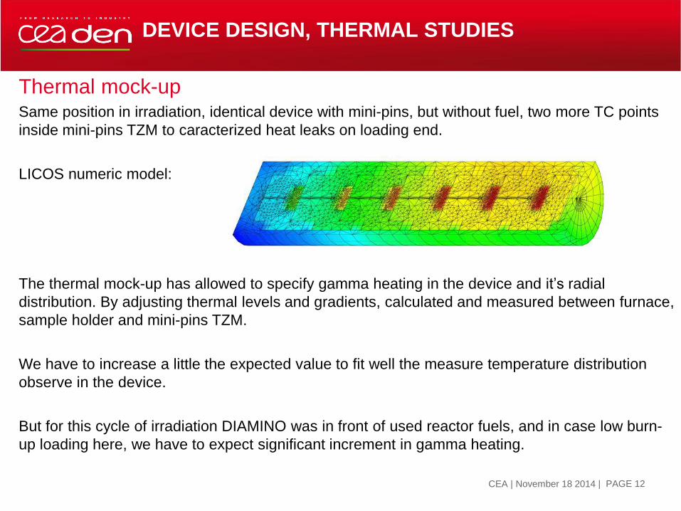
Thermal mock-up Same position in irradiation, identical device with mini-pins, but without fuel, two more TC points
inside mini-pins TZM to caracterized heat leaks on loading end.
LICOS numeric model:
The thermal mock-up has allowed to specify gamma heating in the device and it’s radial
distribution. By adjusting thermal levels and gradients, calculated and measured between furnace,
sample holder and mini-pins TZM.
We have to increase a little the expected value to fit well the measure temperature distribution
observe in the device.
But for this cycle of irradiation DIAMINO was in front of used reactor fuels, and in case low burn-
up loading here, we have to expect significant increment in gamma heating.
DEVICE DESIGN, THERMAL STUDIES
19 NOVEMBRE 2014 | PAGE 12 CEA | November 18 2014

COMPARISON
MEASURED/CALCULATED VALUES
Calculation/measurement comparison for 5 major configurations
19 NOVEMBRE 2014 | PAGE 13 CEA | November 18 2014
Thermal chart for helium gas gaps and heaters turn-
off.
Other cases simulated: Helium gas and furnace at 24%
Helium gas and furnace at 45 %
Helium/neon 50% mix gas and furnace turn-off
Helium/neon 50% mix gas and furnace at 10%
FIRST DIAMINO CYCLE IRRADIATION
But with the increase of the fission power, it would be impossible to limit the
temperature at 600°C and 800 °C within the discs, in same conditions, from the end of
this first cycle.
It appears that we cannot transposed the gamma heating measured in the graphite on
stainless steel in the same way as we do in the core box of the reactor.
The water box was changed for the next irradiations, to back the device off the core.
All thermal and neutronic calculations were updated to take into account, new burn-up
evolution and new gamma heating.
At the beginning of the third cycle, the temperature was as shown on the graph
hereafter.
19 NOVEMBRE 2014 | PAGE 14 CEA | November 18 2014

OTHER CYCLES
Neon gas as been abandoned since the second cycle and the common heater in front of the
mini-pins n°4 and n°5 was turned-off because of the slight overheating of the n°5.
5 cycles for 91 EFPD under irradiation have been currently achieved.
19 NOVEMBRE 2014 | PAGE 15 CEA | November 18 2014

CONCLUSION
After 5 cycles of irradiation in OSIRIS MTR:
It appears that the global thermal behaviour of the device is consistent
with the expected one, with two distinct levels of temperature.
However we have observed a significant overheating of the samples,
due to the underestimation of the gamma heating.
The temperature regulation may be revised upwards without impact on
the objectives of the experiment. Near 880 °C at the end of the
irradiation for the upper loading and near 640 °C lower loading.
Post Irradiation Examination will be drives on fuel discs to caracterized
the behaviour.
19 NOVEMBRE 2014 | PAGE 16 CEA | November 18 2014

Direction
Département
Service
Commissariat à l’énergie atomique et aux énergies alternatives
Centre de Saclay | 91191 Gif-sur-Yvette Cedex
T. +33 (0)1 XX XX XX XX | F. +33 (0)1 XX XX XX XX
Etablissement public à caractère industriel et commercial | RCS Paris B 775 685 019 19 NOVEMBRE 2014
| PAGE 17
CEA | 10 AVRIL 2012