Potable Water Convertible Jet Pumps - Zoeller Pump … · Potable Water Convertible Jet Pumps...
16
FM2537 0415 Supersedes 0513 OWNER’S MANUAL Potable Water Convertible Jet Pumps Safety Instructions CAUTION This manual incorporates the installation, operation, maintenance, and service instructions into one document to aid in the ownership of a Zoeller potable water product. Please read and review this manual before installing the product. Many items contained within, when followed correctly, will not only ensure a long and problem-free life for the system, but also save time and money during installation. Should further assistance be necessary please call our Technical Service department at 1-800-928-PUMP. © Copyright 2015 Zoeller ® Co. All rights reserved. P/N 023072 TO AVOID SERIOUS OR FATAL PERSONAL INJURY OR MAJOR PROPERTY DAMAGE, READ AND FOLLOW ALL SAFETY INSTRUCTIONS IN MANUAL AND ON PUMP. THIS MANUAL IS INTENDED TO ASSIST IN THE INSTALLATION AND OPERATION OF THIS UNIT AND MUST BE KEPT WITH THE PUMP. This is a SAFETY ALERT SYMBOL. When you see this symbol on the pump or in the manual, look for one of the following signal words and be alert to the potential for personal injury or property damage. Warns of hazards that WILL cause serious personal injury, death or major property damage. Warns of hazards that CAN cause serious personal injury, death or major property damage. Warns of hazards that CAN cause personal injury or property damage. Indicates special instructions which are very important and must be followed. THOROUGHLY REVIEW ALL INSTRUCTIONS AND WARNINGS PRIOR TO PERFORMING ANY WORK ON THIS PUMP. MAINTAIN ALL SAFETY DECALS. Table of Contents Safety Instructions .......................................................................... 1 Limited Warranty............................................................................. 2 Preinstallation Information ........................................................... 2-3 Installation Procedures ............................................................... 4-7 Parts List......................................................................................... 7 Troubleshooting Checklist .............................................................. 8 Congratulations on the purchase of the Zoeller Potable Water Convertible Jet Pump. Since 1939 the name Zoeller has represented the standard for submersible sump and sewage pumps. The same high-quality workmanship and easy maintenance design has been incorporated into this line of potable water products. This Zoeller system will provide years of trouble-free service when installed according to the manufacturer recommendations. Owner’s Information Model Number: ______________________ Date Code: _________________ Job Name: ______________________________________________________ Dealer: _________________________________________________________ Date of Purchase: _______________________________________________ Contractor: _____________________________________________________ Date of Installation: _______________________________________________ System Readings During Operation: Voltage __________ Amps _________ Product information presented here reflects conditions at time of publication. Consult factory regarding discrepancies or inconsistencies. MAIL TO: P.O. BOX 16347 • Louisville, KY 40256-0347 SHIP TO: 3649 Cane Run Road • Louisville, KY 40211-1961 (502) 778-2731 • 1 (800) 928-PUMP • FAX (502) 774-3624 visit our web site: www.zoeller.com ® Your Peace of Mind is Our Top Priority ® Register your Zoeller Pump Company Product on our website: http://reg.zoellerpumps.com/
Transcript of Potable Water Convertible Jet Pumps - Zoeller Pump … · Potable Water Convertible Jet Pumps...
FM25370415
Supersedes0513
OWNER’S MANUAL
Potable Water Convertible Jet Pumps
Safety Instructions
CAUTION
This manual incorporates the installation, operation, maintenance, and service instructions into one document to aid in the ownership of a Zoeller potable water product. Please read and review this manual before installing the product. Many items contained within, when followed correctly, will not only ensure a long and problem-free life for the system, but also save time and money during installation. Should further assistance be necessary please call our Technical Service department at 1-800-928-PUMP.
© Copyright 2015 Zoeller® Co. All rights reserved.
P/N
0230
72
TO AVOID SERIOUS OR FATAL PERSONAL INJURY OR MAJOR PROPERTY DAMAGE, READ AND FOLLOW ALL SAFETY INSTRUCTIONS IN MANUAL AND ON PUMP.
THIS MANUAL IS INTENDED TO ASSIST IN THE INSTALLATION AND OPERATION OF THIS UNIT AND MUST BE KEPT WITH THE PUMP.
This is a SAFETY ALERT SYMBOL.When you see this symbol on the pump or in the manual, look for one of the following signal words and be alert to the potential for personal injury or property damage.
Warns of hazards that WILL cause serious personal injury, death or major property damage.
Warns of hazards that CAN cause serious personal injury, death or major property damage.
Warns of hazards that CAN cause personal injury or property damage.
Indicates special instructions which are very important and must be followed.
THOROUGHLY REVIEW ALL INSTRUCTIONS AND WARNINGS PRIOR TO PERFORMING ANY WORK ON THIS PUMP.
MAINTAIN ALL SAFETY DECALS.
Table of ContentsSafety Instructions .......................................................................... 1
Limited Warranty............................................................................. 2
Preinstallation Information ...........................................................2-3
Installation Procedures ...............................................................4-7
Parts List ......................................................................................... 7
Troubleshooting Checklist .............................................................. 8
Congratulations on the purchase of the Zoeller Potable Water Convertible Jet Pump. Since 1939 the name Zoeller has represented the standard for submersible sump and sewage pumps. The same high-quality workmanship and easy maintenance design has been incorporated into this line of potable water products. This Zoeller system will provide years of trouble-free service when installed according to the manufacturer recommendations.
Owner’s InformationModel Number: ______________________ Date Code: _________________
Job Name: ______________________________________________________
Dealer: _________________________________________________________
Date of Purchase: _______________________________________________
Contractor: _____________________________________________________
Date of Installation: _______________________________________________
System Readings During Operation: Voltage __________ Amps _________
SEND TERESA BOWSMAN @ F&W A PDF WHEN THIS FILE IS CHANGED.
Product information presented here reflects conditions at time of publication. Consult factory regarding discrepancies or inconsistencies.
MAIL TO: P.O. BOX 16347 • Louisville, KY 40256-0347SHIP TO: 3649 Cane Run Road • Louisville, KY 40211-1961
(502) 778-2731 • 1 (800) 928-PUMP • FAX (502) 774-3624
visit our web site:www.zoeller.com
®
Your Peace of Mind is Our Top Priority ®
Register your Zoeller Pump Company Product on our website:
http://reg.zoellerpumps.com/
2© Copyright 2015 Zoeller® Co. All rights reserved.
LIMITED WARRANTYManufacturer warrants, to the purchaser and subsequent owner during the warranty period, every new product to be free from defects in material and workmanship under normal use and service, when properly used and maintained, for a period of one year from date of purchase by the end user, or 18 months from date of original manufacture of the product, whichever comes first. Parts that fail within the warranty period, one year from date of purchase by the end user, or 18 months from the date of original manufacture of the product, whichever comes first, that inspections determine to be defective in material or workmanship, will be repaired, replaced or remanufactured at Manufacturer's option, provided however, that by so doing we will not be obligated to replace an entire assembly, the entire mechanism or the complete unit. No allowance will be made for shipping charges, damages, labor or other charges that may occur due to product failure, repair or replacement.
This warranty does not apply to and there shall be no warranty for any material or product that has been disassembled without prior approval of Manufacturer, subjected to misuse, misapplication, neglect, alteration, accident or act of nature; that has not been installed, operated or maintained in accordance with Manufacturer's installation instructions; that has been exposed to outside substances including but not limited to the following: sand, gravel, cement, mud, tar, hydrocarbons, hydrocarbon derivatives (oil, gasoline, solvents, etc.), or other abrasive or corrosive substances, wash towels or feminine sanitary products,
etc. in all applications. The warranty set out in the paragraph above is in lieu of all other warranties expressed or implied; and we do not authorize any representative or other person to assume for us any other liability in connection with our products.
Contact Manufacturer at, 3649 Cane Run Road, Louisville, Kentucky 40211, Attention: Customer Support Department to obtain any needed repair or replacement of part(s) or additional information pertaining to our warranty.
MANUFACTURER EXPRESSLY DISCLAIMS LIABILITY FOR SPECIAL, CONSEQUENTIAL OR INCIDENTAL DAMAGES OR BREACH OF EXPRESSED OR IMPLIED WARRANTY; AND ANY IMPLIED WARRANTY OF FITNESS FOR A PARTICULAR PURPOSE AND OF MERCHANTABILITY SHALL BE LIMITED TO THE DURATION OF THE EXPRESSED WARRANTY.
Some states do not allow limitations on the duration of an implied warranty, so the above limitation may not apply to you. Some states do not allow the exclusion or limitation of incidental or consequential damages, so the above limitation or exclusion may not apply to you.
This warranty gives you specific legal rights and you may also have other rights which vary from state to state.
PREINSTALLATION INFORMATION 6. DO NOT run the pump dry. DO NOT run the pump
with a completely closed discharge. DO NOT pump chemical or corrosive liquids. Failure to follow above warnings could result in damage to the pump, voiding the warranty and causing personal injury.
7. CAUTION Check to be sure your power source is capable of handling the voltage requirements of the motor, as indicated on the pump nameplate.
8. CAUTION Water hammer creates momentary high pressure surges. These surges can cause severe damage to check valves and the piping system. Consideration for water hammer must be included in the piping system design. Reference ASPE Data Book, Chapter 2.33. Some systems may require external spring or lever weighted check valves or other engineered solutions.
9. According to the state of California (Prop 65), this product contains chemicals known to the state of California to cause cancer and birth defects or other reproductive harm.
1. Inspect your unit. Occasionally, products are damaged during shipment. If the unit is damaged, contact your dealer before using.
2. Carefully read the literature provided to familiarize yourself with specific details regarding installation and use. These materials should be retained for future reference.
3. Do not lift, carry, or hang pump by the electrical cables. Damage to the electrical cables can cause shock, burns or death. 4. Make sure the pump electrical supply
circuit is equipped with fuses or circuit breakers of proper capacity. A separate branch circuit is recommended, and
sized according to the “National Electrical Code” for the current shown on the pump nameplate.
5. Pump is designed to pump cold ground water that is free of air or gases. Decreased pump performance and life expectancy can occur if the ground water is not cold (86ºF/30ºC) or contains air or gases.
3© Copyright 2015 Zoeller® Co. All rights reserved.
SAFETY INFORMATION
DANGER: 1. Always disconnect power source before performing any work on
or near the motor or its connected load. If the power disconnect point is out-of-sight, lock it in the open position and tag it to prevent unexpected application of power. Failure to do so could result in fatal electrical shock.
2. Do not handle the pump with wet hands or when standing in water as fatal electrical shock could occur. Disconnect main power before handling unit for ANY REASON!
3. RISK OF ELECTRIC SHOCK. These pumps have not been investigated for use in swimming pool areas.
WARNING: 1. Follow all local electrical and safety codes, as well as the
National Electrical Code (NEC) and the Occupational Safety and Health Act (OSHA).
2. Replace damaged or worn wiring cord immediately.3. Do not kink power cable and never allow the cable to come in
contact with oil, grease, hot surfaces, or chemicals.4. Wire motor to correct supply voltage - see motor nameplate and
wiring diagrams and check voltage of power supply.5. Unit must be securely and adequately electrically grounded.
This can be accomplished by wiring the unit to a ground metal-clad raceway system or by using a separate ground wire connected to the bare metal of the motor frame or other suitable means.
6. Hazardous Pressure! Install pressure relief valve in discharge pipe. Release all pressure on system before working on any component.
7. Do not use to pump flammable or explosive fluids such as gasoline, fuel oil, kerosene, etc. Do not use in flammable and/or explosive atmospheres.
CAUTION: 1. Protect the power cable from coming in contact with sharp
objects.2. Be careful when touching the exterior of an operating motor - It
may be hot enough to be painful or cause injury.3. Make certain that the power source conforms to the
requirements of your equipment.4. Do not run pump dry.5. Pump and plumbing must be full of water before startup.6. Do not pump water which contains sand, mud, silt, or debrisNOTE: Pumps with the “UL” Mark and pumps with the “US” mark are tested to UL Standard UL778.CSA certified pumps are certified to CSA Standard C22.2 No. 108. (CUS)
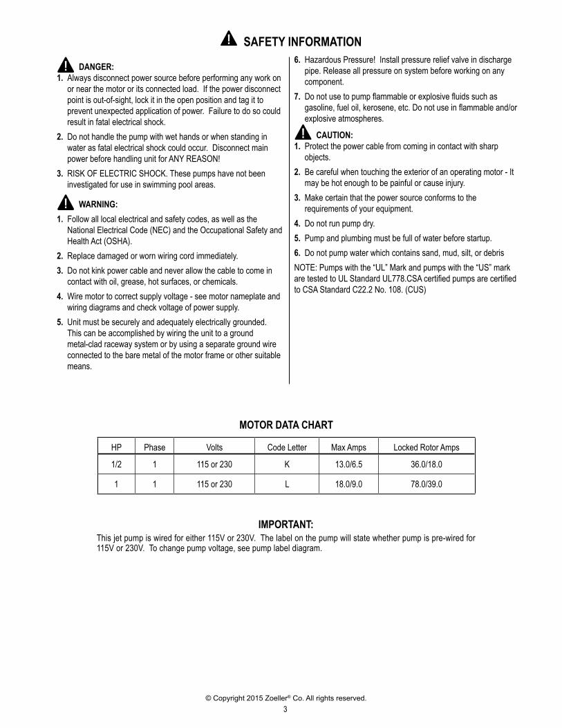
MOTOR DATA CHART
HP Phase Volts Code Letter Max Amps Locked Rotor Amps
1/2 1 115 or 230 K 13.0/6.5 36.0/18.0
1 1 115 or 230 L 18.0/9.0 78.0/39.0
IMPORTANT:This jet pump is wired for either 115V or 230V. The label on the pump will state whether pump is pre-wired for 115V or 230V. To change pump voltage, see pump label diagram.
4© Copyright 2015 Zoeller® Co. All rights reserved.
READ THESE INSTRUCTIONS CAREFULLY BEFORE INSTALLATIONLOCATION1. Pump can be located at the well or can be offset some distance
away from the well. For best performance it should be located as close to the well as possible. The horizontal distance is the horizotal measurement between pump suction and the water source. This distance may affect the ability of the pump to operate. If over 100', contact the Manufacturer for assistance.
2. Location can be in the basement, a pit below ground or in a pump house above ground.
3. Ventilation and drainage must be provided to prevent damage from moisture to the motor and pressure switch.
4. The pump and all piping must be protected from freezing.5. Pump and pipe line must be drained when not in use if there is
any danger of freezing.
WELL CONDITIONS1. New wells should be pumped clean of all sand and foreign matter
before installing the pump or damage may result to the operating parts.
2. The foot valve should be installed a minimum of five (5) feet from the bottom of the well to prevent sand, mud or other foreign matter from entering the system.
3. The well must be capable of furnishing a sufficient quantity of water to satisfy the demands of the pump and personal needs. The water level must not draw down below the maximum rated depth of the pump or loss of capacity and prime will result.
4. For weak well installations, see Paragraph #1 under Deep Well (Double Pipe System) Installations (Page 5).
5. For sanitary reasons, install a well seal or pitless adapter as required and in accordance with local and state codes.
PIPING1. Old or badly scaled pipe should not be used because dislodged
flakes of scale can cause stoppage of the ejector nozzle and malfunction the entire system.
2. Use only pipe in good condition free from rust and scale. Threads should be sharp, cleanly cut with a minimum of two (2) threads remaining when connection is completely drawn up.
3. On galvanized steel pipe installations, the ends should be reamed to insure maximum capacity.
4. All joints and connections should be doped (male threads only) and drawn up tightly. CAUTION The entire system must be air and water
tight for efficient operation.
TYPE OF PIPE1. Plastic or galvanized steel pipe may be used in the installation of
jet pumps.2. Plastic pipe must have a minimum pressure rating of 160 PSI.3. Never use flexible plastic pipe and insert adapters on deep well
single pipe ejector applications.
WELL TO PUMP PIPING1. All offset piping should slope upwards from well to pump.2. Avoid dips or pockets in offset piping or air will accumulate at high
points which will make priming difficult.3. Install unions at pump and at well to aid in servicing.4. Allow enough room around pump and piping installation for using
pipe wrenches and for service and installation.5. Do not use piping of sizes smaller than those listed in Charts 1
and 2 or pump will not operate properly.NOTE: For the pump to operate, the venturi tube of the ejector must be positioned into the top tapping of the face of the pump.CONTROL BODY AND PRESSURE SWITCH ATTACHMENT1. To assure leak free connections, use Teflon tape or pipe dope
on all switch and pipe threads. Tighten all connections by hand plus 1-1/2 additional turns.
2. Use pipe dope on external threads of all plumbing connections.
5© Copyright 2015 Zoeller® Co. All rights reserved.
Tools required
PREPARATION
Pipe wrenches (2)Wire strippersNeedle-nose pliersPhillips screwdriver
Adjustable wrenchPipe tapePipe dopeWire cutters
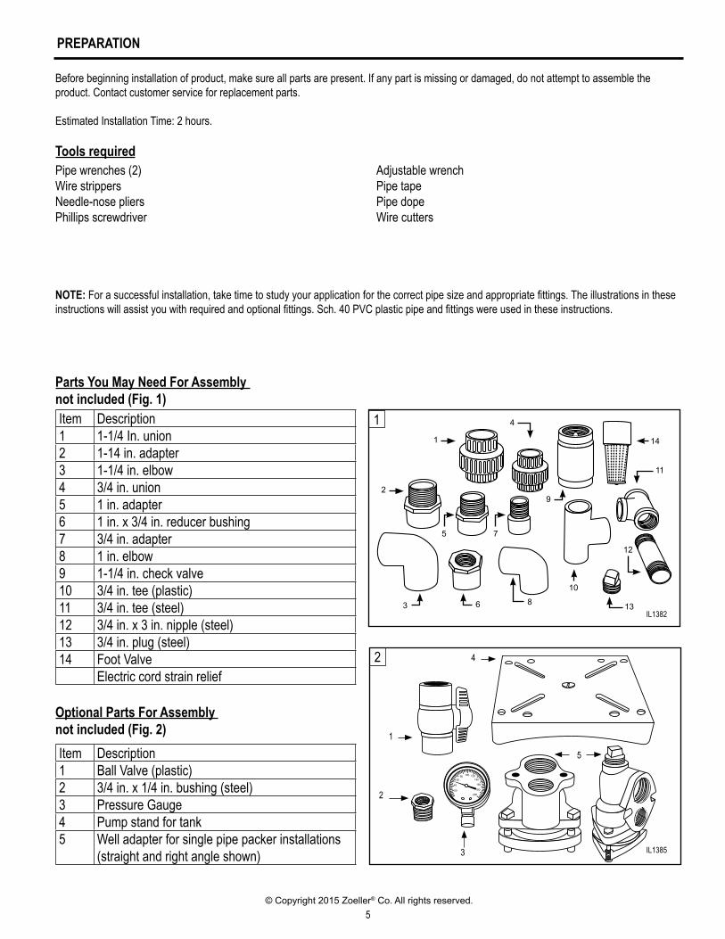
Parts You May Need For Assembly not included (Fig. 1)Item Description1 1-1/4 In. union2 1-14 in. adapter3 1-1/4 in. elbow4 3/4 in. union5 1 in. adapter6 1 in. x 3/4 in. reducer bushing7 3/4 in. adapter8 1 in. elbow9 1-1/4 in. check valve10 3/4 in. tee (plastic)11 3/4 in. tee (steel)12 3/4 in. x 3 in. nipple (steel)13 3/4 in. plug (steel)14 Foot Valve
Electric cord strain relief
Optional Parts For Assembly not included (Fig. 2)Item Description1 Ball Valve (plastic)2 3/4 in. x 1/4 in. bushing (steel)3 Pressure Gauge4 Pump stand for tank5 Well adapter for single pipe packer installations
(straight and right angle shown)
NOTE: For a successful installation, take time to study your application for the correct pipe size and appropriate fittings. The illustrations in these instructions will assist you with required and optional fittings. Sch. 40 PVC plastic pipe and fittings were used in these instructions.
Before beginning installation of product, make sure all parts are present. If any part is missing or damaged, do not attempt to assemble the product. Contact customer service for replacement parts.
Estimated Installation Time: 2 hours.
IL1385
lııılı
ııılıı
ılıııı
lııılıııılııılıııılııılıııılııılıııı 200
180
160
14012010080
60
40
20
1
2
3
42
5
1
IL1382
4
1
2
5 7
9
14
11
3 6 8
10
13
12
IL1382
IL1385
6© Copyright 2015 Zoeller® Co. All rights reserved.
INSTALLING PIPING IN WELL
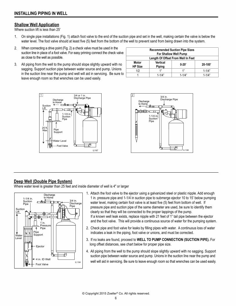
Shallow Well Application Where suction lift is less than 25'
1. On single pipe installations (Fig. 1) attach foot valve to the end of the suction pipe and set in the well, making certain the valve is below the water level. The foot valve should at least five (5) feet from the bottom of the well to prevent sand from being drawn into the system.
2. When connecting a drive point (Fig. 2) a check valve must be used in the suction line in place of a foot valve. For easy priming connect the check valve as close to the well as possible.
3. All piping from the well to the pump should slope slightly upward with no sagging. Support suction pipe between water source and pump. Unions in the suction line near the pump and well will aid in servicing. Be sure to leave enough room so that wrenches can be used easily.
Water Level
25 ft.Max
Suction Lift
3/4 or 1 in. Discharge Pipe
1-1/4 in.SuctionPipe
Discharge to Home
Pipe Support
Foot Valve
1
IL1188
3/4 in. Discharge Pipe
1-1/4 in.SuctionPipe
Discharge to Home
2
Recommended Suction Pipe SizesFor Shallow Well Pump
Length Of Offset From Well In FeetMotor
HP SizeVertical Piping 0-20’ 20-100’
1/2 1” 1” 1-1/4”1 1-1/4” 1-1/4” 1-1/4”
Deep Well (Double Pipe System)Where water level is greater than 25 feet and inside diameter of well is 4" or larger
1. Attach the foot valve to the ejector using a galvanized steel or plastic nipple. Add enough 1 in. pressure pipe and 1-1/4 in suction pipe to submerge ejector 10 to 15’ below pumping water level, making certain foot valve is at least five (5) feet from bottom of well. If pressure pipe and suction pipe of the same diameter are used, be sure to identify them clearly so that they will be connected to the proper tappings of the pump.
If a known well leak exists, replace nipple with 21 feet of 1” tail pipe between the ejector and the foot valve. This will provide a continuous source of water for the pumping system.
2. Check pipe and foot valve for leaks by filling pipes with water. A continuous loss of water indicates a leak in the piping, foot valve or unions, and must be corrected.
3. If no leaks are found, proceed to WELL TO PUMP CONNECTION (SUCTION PIPE). For long offset distances, see chart below for proper pipe size.
4. All piping from the well to the pump should slope slightly upward with no sagging. Support suction pipe between water source and pump. Unions in the suction line near the pump and well will aid in servicing. Be sure to leave enough room so that wrenches can be used easily.IL1184
Water Level
Suction Lift
3/4 in. Discharge Pipe
1-1/4 in.SuctionPipe
Discharge to Home
Pipe Support
Foot Valve
1 in.PressurePipe
4 in. ID Well
Ejector
IL1187
7© Copyright 2015 Zoeller® Co. All rights reserved.
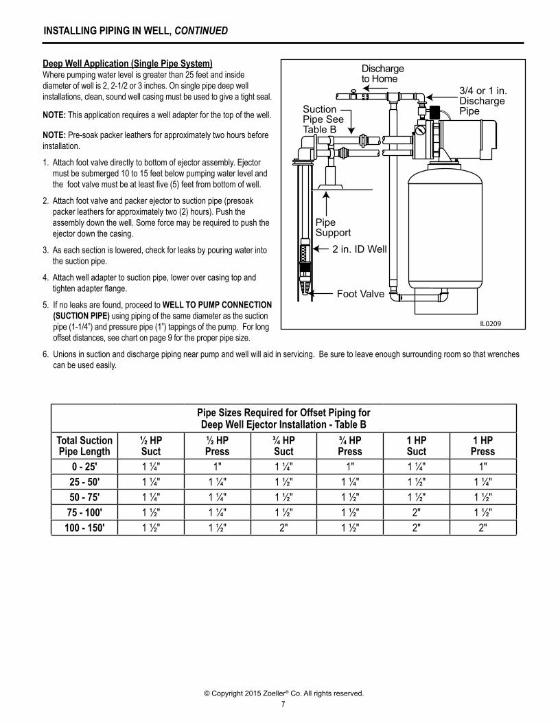
Deep Well Application (Single Pipe System)Where pumping water level is greater than 25 feet and inside diameter of well is 2, 2-1/2 or 3 inches. On single pipe deep well installations, clean, sound well casing must be used to give a tight seal.
NOTE: This application requires a well adapter for the top of the well.
NOTE: Pre-soak packer leathers for approximately two hours before installation.
1. Attach foot valve directly to bottom of ejector assembly. Ejector must be submerged 10 to 15 feet below pumping water level and the foot valve must be at least five (5) feet from bottom of well.
2. Attach foot valve and packer ejector to suction pipe (presoak packer leathers for approximately two (2) hours). Push the assembly down the well. Some force may be required to push the ejector down the casing.
3. As each section is lowered, check for leaks by pouring water into the suction pipe.
4. Attach well adapter to suction pipe, lower over casing top and tighten adapter flange.
5. If no leaks are found, proceed to WELL TO PUMP CONNECTION (SUCTION PIPE) using piping of the same diameter as the suction pipe (1-1/4”) and pressure pipe (1”) tappings of the pump. For long offset distances, see chart on page 9 for the proper pipe size.
6. Unions in suction and discharge piping near pump and well will aid in servicing. Be sure to leave enough surrounding room so that wrenches can be used easily.
IL0209
3/4 or 1 in. Discharge PipeSuction
Pipe SeeTable B
Discharge to Home
Pipe Support
Foot Valve
2 in. ID Well
INSTALLING PIPING IN WELL, CONTINUED
Pipe Sizes Required for Offset Piping forDeep Well Ejector Installation - Table B
Total SuctionPipe Length
½ HPSuct
½ HPPress
¾ HPSuct
¾ HPPress
1 HPSuct
1 HPPress
0 - 25' 1 ¼" 1" 1 ¼" 1" 1 ¼" 1"25 - 50' 1 ¼" 1 ¼" 1 ½" 1 ¼" 1 ½" 1 ¼"50 - 75' 1 ¼" 1 ¼" 1 ½" 1 ½" 1 ½" 1 ½"
75 - 100' 1 ½" 1 ¼" 1 ½" 1 ½" 2" 1 ½"100 - 150' 1 ½" 1 ½" 2" 1 ½" 2" 2"
8© Copyright 2015 Zoeller® Co. All rights reserved.
WELL TO PUMP CONNECTION (SUCTION PIPE)
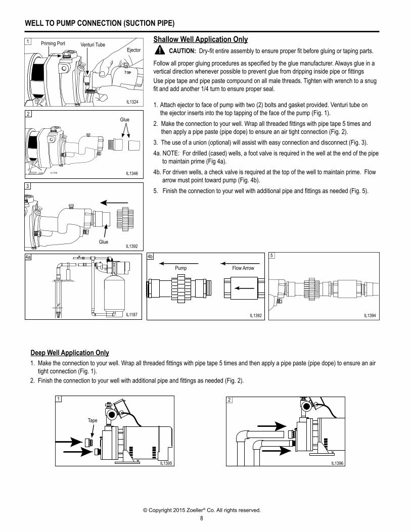
1. Attach ejector to face of pump with two (2) bolts and gasket provided. Venturi tube on the ejector inserts into the top tapping of the face of the pump (Fig. 1).2. Make the connection to your well. Wrap all threaded fittings with pipe tape 5 times and
then apply a pipe paste (pipe dope) to ensure an air tight connection (Fig. 2).3. The use of a union (optional) will assist with easy connection and disconnect (Fig. 3).4a. NOTE: For drilled (cased) wells, a foot valve is required in the well at the end of the pipe to maintain prime (Fig 4a).4b. For driven wells, a check valve is required at the top of the well to maintain prime. Flow arrow must point toward pump (Fig. 4b).5. Finish the connection to your well with additional pipe and fittings as needed (Fig. 5).
Shallow Well Application Only CAUTION: Dry-fit entire assembly to ensure proper fit before gluing or taping parts.
Follow all proper gluing procedures as specified by the glue manufacturer. Always glue in a vertical direction whenever possible to prevent glue from dripping inside pipe or fittingsUse pipe tape and pipe paste compound on all male threads. Tighten with wrench to a snug fit and add another 1/4 turn to ensure proper seal.
IL1324
Priming Port Venturi TubeEjector
1
IL1346
2Glue
3
IL1392
Glue
IL1394
5
IL1396
2
IL1395
1
Tape
1. Make the connection to your well. Wrap all threaded fittings with pipe tape 5 times and then apply a pipe paste (pipe dope) to ensure an air tight connection (Fig. 1).
2. Finish the connection to your well with additional pipe and fittings as needed (Fig. 2).
Deep Well Application Only
IL1324
IL1346
IL1392
IL1394
IL1395 IL1396
4a 4b
IL1475
Pump Flow Arrow
IL1392
Flow ArrowPump
IL1187
9© Copyright 2015 Zoeller® Co. All rights reserved.
PUMP TO PRESSURE TANK CONNECTION (DISCHARGE PIPE)
IL1400
IL1397
1
IL1398
2
IL1399
3
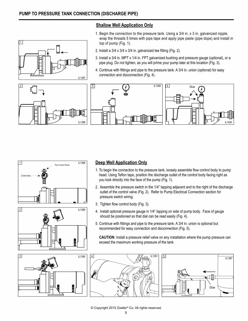
Shallow Well Application Only1. Begin the connection to the pressure tank. Using a 3/4 in. x 3 in. galvanized nipple,
wrap the threads 5 times with pipe tape and apply pipe paste (pipe dope) and install in top of pump (Fig. 1).
2. Install a 3/4 x 3/4 x 3/4 in. galvanized tee fitting (Fig. 2).
3. Install a 3/4 in. MPT x 1/4 in. FPT galvanized bushing and pressure gauge (optional), or a pipe plug. Do not tighten, as you will prime your pump later at this location (Fig. 3).
4. Continue with fittings and pipe to the pressure tank. A 3/4 in. union (optional) for easy connection and disconnection (Fig. 4).
4 Glue
IL1388
1
IL1389
2
IL1390
3
Control Body
Flow Control Screw
IL1391
4
IL1387
5
Glue
Deep Well Application Only1. To begin the connection to the pressure tank, loosely assemble flow control body to pump
head. Using Teflon tape, position the discharge outlet of the control body facing right as you look directly into the face of the pump (Fig. 1).
2. Assemble the pressure switch in the 1/4” tapping adjacent and to the right of the discharge outlet of the control valve (Fig. 2). Refer to Pump Electrical Connection section for pressure switch wiring.
3. Tighten flow control body (Fig. 3).
4. Install optional pressure gauge in 1/4” tapping on side of pump body. Face of gauge should be positioned so that dial can be read easily (Fig. 4).
5. Continue with fittings and pipe to the pressure tank. A 3/4 in. union is optional but recommended for easy connection and disconnection (Fig. 5).
CAUTION: Install a pressure relief valve on any installation where the pump pressure can exceed the maximum working pressure of the tank.
IL1397
IL1398
IL1399
IL1400
IL1388
IL1389
IL1390 IL1391IL1387
10© Copyright 2015 Zoeller® Co. All rights reserved.
TANK TO HOUSE CONNECTION
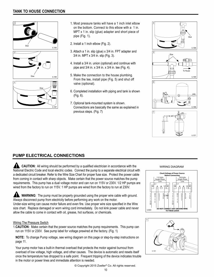
1. Most pressure tanks will have a 1 inch inlet elbow on the bottom. Connect to this elbow with a 1 in. MPT x 1 in. slip (glue) adapter and short piece of pipe (Fig. 1).
2. Install a 1 inch elbow (Fig. 2).
3. Attach a 1 in. slip (glue) x 3/4 in. FPT adapter and 3/4 in. MPT x 3/4 in. slip (Fig. 3).
4. Install a 3/4 in. union (optional) and continue with pipe and 3/4 in. x 3/4 in. x 3/4 in. tee (Fig. 4).
5. Make the connection to the house plumbing. From the tee, install pipe (Fig. 5) and shut off valve (optional).
6. Completed installation with piping and tank is shown (Fig. 6).
7. Optional tank-mounted system is shown. Connections are basically the same as explained in previous steps. (Fig. 7)
IL1365
1
Glue
IL1366
2
Glue
IL1367
3
Glue
IL1368
4
Glue
IL1386
6
IL1369
5Glue
To House
L1L2A B
L1L2A B
115 VoltsSingle Phase
Line
230 VoltsSingle Phase
Line
YELLOW
WHITE
GREY
RED
TAN
YELLOW
WHITE
GREY
RED
TAN
Check Voltage of Power SourceBefore Connecting
DO NOT CONNECT ANY GROUND WIRE TO THESE LEADS
WIRING DIAGRAM
Wiring The Pressure Switch1.CAUTION: Make certain that the power source matches the pump requirements. This pump can run on 115V or 230V. See pump label for voltage prewired at the factory. (Fig. 1)
NOTE: To change Pump voltage, see wiring diagram on this page or step-by-step instructions on page 11.
Your pump motor has a built-in thermal overload that protects the motor against burnout from overload of low voltage, high voltage, and other causes. The device is automatic and resets itself once the temperature has dropped to a safe point. Frequent tripping of the device indicates trouble in the motor or power lines and immediate attention is needed.
CAUTION: All wiring should be performed by a qualified electrician in accordance with the National Electric Code and local electric codes. Connect the pump to a separate electrical circuit with a dedicated circuit breaker. Refer to the Wire Size Chart for proper fuse size. Protect the power cable from coming in contact with sharp objects. Make certain that the power source matches the pump requirements. This pump has a dual voltage motor and can run on 115V or 230V. 1/2 HP pumps are wired from the factory to run on 115V. 1 HP pumps are wired from the factory to run at 230V.
WARNING: The pump must be properly grounded using the proper wire cable with ground. Always disconnect pump from electricity before performing any work on the motor.Under-size wiring can cause motor failure and even fire. Use proper wire size specified in the Wire size chart. Replace damaged or worn wiring cord immediately. Do not kink power cable and never allow the cable to come in contact with oil, grease, hot surfaces, or chemicals.
PUMP ELECTRICAL CONNECTIONS
IL1401
1
IL1365
IL1366
IL1367
IL1368
IL1369
IL1386
IL0924
IL1401
IL1371
7
11© Copyright 2015 Zoeller® Co. All rights reserved.
PUMP ELECTRICAL CONNECTIONS, CONTINUED
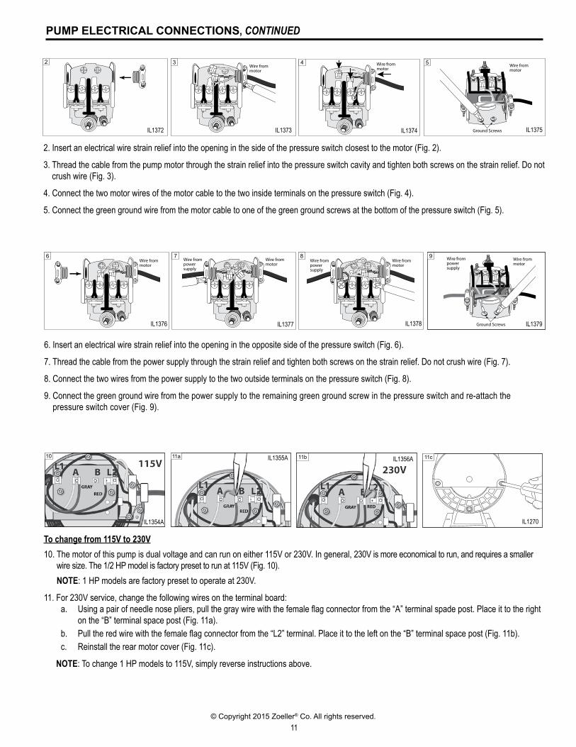
2. Insert an electrical wire strain relief into the opening in the side of the pressure switch closest to the motor (Fig. 2).
3. Thread the cable from the pump motor through the strain relief into the pressure switch cavity and tighten both screws on the strain relief. Do not crush wire (Fig. 3).
4. Connect the two motor wires of the motor cable to the two inside terminals on the pressure switch (Fig. 4).
5. Connect the green ground wire from the motor cable to one of the green ground screws at the bottom of the pressure switch (Fig. 5).
IL1372
2
IL1373
Wire from motor
3
IL1374
Wire from motor
4
IL1375
Wire from motor
Ground Screws
5
IL1376
Wire from motor
6
IL1377
Wire from motor
Wire from powersupply
7
IL1378
Wire from motor
Wire from powersupply
8
IL1379
Wire from motor
Wire from powersupply
Ground Screws
9
6. Insert an electrical wire strain relief into the opening in the opposite side of the pressure switch (Fig. 6).
7. Thread the cable from the power supply through the strain relief and tighten both screws on the strain relief. Do not crush wire (Fig. 7).
8. Connect the two wires from the power supply to the two outside terminals on the pressure switch (Fig. 8).
9. Connect the green ground wire from the power supply to the remaining green ground screw in the pressure switch and re-attach the pressure switch cover (Fig. 9).
10 11a 11b 11c
To change from 115V to 230V10. The motor of this pump is dual voltage and can run on either 115V or 230V. In general, 230V is more economical to run, and requires a smaller
wire size. The 1/2 HP model is factory preset to run at 115V (Fig. 10). NOTE: 1 HP models are factory preset to operate at 230V.
11. For 230V service, change the following wires on the terminal board:a. Using a pair of needle nose pliers, pull the gray wire with the female flag connector from the “A” terminal spade post. Place it to the right
on the “B” terminal space post (Fig. 11a).b. Pull the red wire with the female flag connector from the “L2” terminal. Place it to the left on the “B” terminal space post (Fig. 11b).c. Reinstall the rear motor cover (Fig. 11c).
NOTE: To change 1 HP models to 115V, simply reverse instructions above.
IL1372 IL1373 IL1374 IL1375
IL1376 IL1377 IL1378 IL1379
IL1354A
IL1355A IL1356A
IL1270
12© Copyright 2015 Zoeller® Co. All rights reserved.
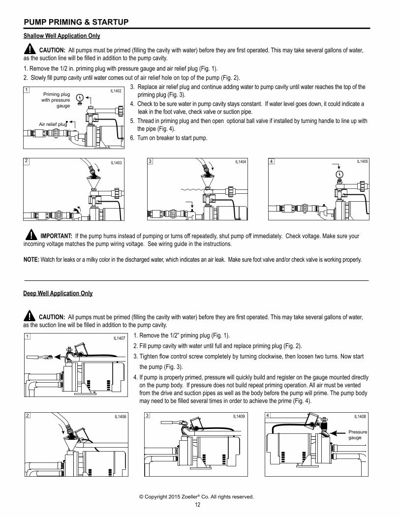
PUMP PRIMING & STARTUPShallow Well Application Only
CAUTION: All pumps must be primed (filling the cavity with water) before they are first operated. This may take several gallons of water, as the suction line will be filled in addition to the pump cavity.1. Remove the 1/2 in. priming plug with pressure gauge and air relief plug (Fig. 1).2. Slowly fill pump cavity until water comes out of air relief hole on top of the pump (Fig. 2).
3. Replace air relief plug and continue adding water to pump cavity until water reaches the top of the priming plug (Fig. 3).
4. Check to be sure water in pump cavity stays constant. If water level goes down, it could indicate a leak in the foot valve, check valve or suction pipe.5. Thread in priming plug and then open optional ball valve if installed by turning handle to line up with
the pipe (Fig. 4).6. Turn on breaker to start pump.
IMPORTANT: If the pump hums instead of pumping or turns off repeatedly, shut pump off immediately. Check voltage. Make sure your incoming voltage matches the pump wiring voltage. See wiring guide in the instructions.
NOTE: Watch for leaks or a milky color in the discharged water, which indicates an air leak. Make sure foot valve and/or check valve is working properly.
IL1403IL1404
3
IL1405
4
Deep Well Application Only
CAUTION: All pumps must be primed (filling the cavity with water) before they are first operated. This may take several gallons of water, as the suction line will be filled in addition to the pump cavity.
1. Remove the 1/2” priming plug (Fig. 1).2. Fill pump cavity with water until full and replace priming plug (Fig. 2).3. Tighten flow control screw completely by turning clockwise, then loosen two turns. Now start
the pump (Fig. 3).4. If pump is properly primed, pressure will quickly build and register on the gauge mounted directly
on the pump body. If pressure does not build repeat priming operation. All air must be vented from the drive and suction pipes as well as the body before the pump will prime. The pump body may need to be filled several times in order to achieve the prime (Fig. 4).
IL1406
2
IL1403 IL1404 IL1405
IL1406 IL1409 IL1408
2
IL1402
1Priming plug
with pressure gauge
Air relief plug
IL1407
1
IL1409
3
IL1408
4
Pressure gauge
IL1402
IL1407
13© Copyright 2015 Zoeller® Co. All rights reserved.
PUMP PRIMING & STARTUP, CONTINUED
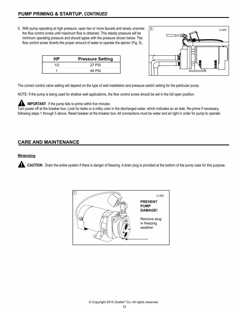
5. With pump operating at high pressure, open two or more faucets and slowly unscrew the flow control screw until maximum flow is obtained. This steady pressure will be minimum operating pressure and should agree with the pressure shown below. The flow control screw diverts the proper amount of water to operate the ejector (Fig. 5).
The correct control valve setting will depend on the type of well installation and pressure switch setting for the particular pump.
NOTE: If the pump is being used for shallow well applications, the flow control screw should be set in the full open position.
IMPORTANT: If the pump fails to prime within five minutes:Turn power off at the breaker box. Look for leaks or a milky color in the discharged water, which indicates an air leak. Re-prime if necessary, following steps 1 through 5 above. Reset breaker at the breaker box. All connections must be water and air tight in order for pump to operate.
IL1409
5
CARE AND MAINTENANCE
Winterizing
CAUTION: Drain the entire system if there is danger of freezing. A drain plug is provided at the bottom of the pump case for this purpose.
HP Pressure Setting1/2 27 PSI1 46 PSI
IL1409
IL0345
1
PREVENT PUMP DAMAGE!
Remove plug in freezing weather
IL1409
14© Copyright 2015 Zoeller® Co. All rights reserved.
SEAL ASSEMBLY AND MOTOR REPLACEMENT
ROTARY SEAL ASSEMBLY REPLACEMENT
CAUTION Make certain that the power supply is disconnected before attempting to service the unit! The rotary seal assembly must be handled carefully to avoid damaging the precision lapped faces of the sealing components.
1. Disengage pump body (Ref. No. 10) from motor mounting ring (Ref. No. 2).
2. Remove diffuser (Ref. No. 6).
3. To remove the impeller use a 9/16" open end wrench to hold the motor shaft. On Uni-frame motors, remove the rear cover, the flat area is located between the governor and rear bearing. On Nema J motors, the shaft flat area is located in the middle of the mounting ring. Uni-frame or Nema J motors are indicated by 56U or 56J respectively in the frame "FR" block on the motor decal.
4. The rotary seal (Ref. No. 4) will come loose at this time. Use a screwdriver (or similar instrument) to pry the ceramic seal and rubber gasket from the recess of the mounting bracket.
CAUTION Be careful not to damage the motor shaft or recess surface.
5. Clean the recess and motor shaft thoroughly.6. Install the new rotary seal assembly. a. Insert the ceramic seal and the rubber gasket into the recess.NOTE: To help facilitate installation, apply a drop of liquid soap to the outside diameter of the rubber gasket. Make certain that the ceramic seal is kept clean and free of dirt and/or oil. b. Slip the remaining parts of the rotary seal assembly onto the
motor shaft.NOTE: Apply a drop of liquid soap to the inside diameter of the rubber drive ring.
7. Replace the impeller and diffuser removed in Steps 2 & 3.8. Reassemble the pump body to the motor and mounting bracket.
MOTOR REPLACEMENT (Figure 5)
1. Uni-Frame motors can be replaced in the field with any standard Nema J jet pump motor by following the instructions below.CAUTION Before attempting to replace the motor,
make certain that the power supply is disconnected and the system pressure is relieved.
2. Remove pump body (Ref. No. 10), diffuser (Ref. No. 6), impeller (Ref. No. 5), and shaft seal (Ref. No. 4) by following steps 1, 2, 3 & 4 of Rotary Seal Replacement.
3. Uni-Frame motors (indicated by 56U in the frame “FR” block on the motor decal) can be removed as follows:
a. Disassemble pump base (Ref. No. 14) from unit by removing two (2) 3/8” hex nuts.
b. Remove four (4) thru bolts from rear of motor and pull away shell and stator assembly (discard).
c. Disconnect four (4) self tapping screws that hold the bearing housing to the mounting ring. Discard bearing housing, rotor assembly and (2) square headed screws.
4. Replace motor with standard Nema J jet pump motor by positioning motor against the mounting frame and assembling with four (4) 3/8” x 3/4” cap screws. The mounting base is connected at the bottom of the mounting frame with two (2) of the four (4) 3/8” x 3/4” cap screws.
5. Follow steps 5, 6, 7 and 8 of Rotor Seal Assembly to reassemble the remainder of the pump. Because damage to the shaft seal is most likely to occur in disassembly, a new seal will be necessary.
NOTE: The pumps and motors require no lubrication. The ball bearings of the motor have been greased at the factory and under normal operating conditions should require no further greasing.
15© Copyright 2015 Zoeller® Co. All rights reserved.
IL0350
15
2
3
4
5
6
7
12
8
9
10
11
1
14
13
10
12
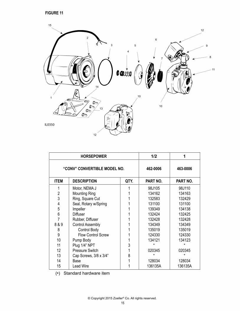
HORSEPOWER 1/2 1
“CONV” CONVERTIBLE MODEL NO. 462-0006 463-0006
ITEM DESCRIPTION QTY. PART NO. PART NO.1234567
8 & 989101112131415
Motor, NEMA JMounting RingRing, Square CutSeal, Rotary w/SpringImpellerDiffuserRubber, DiffuserControl Assembly Control Body Flow Control ScrewPump BodyPlug 1/4” NPTPressure SwitchCap Screws, 3/8 x 3/4”BaseLead Wire
1111111111131811
98J105134162132583131100139349132424132428134349135019124330134121
*020345
*128034
136135A
98J110134163132429131100134138132425132428134349135019124330134123
*020345
*128034
136135A (*) Standard hardware item
FIGURE 11
16© Copyright 2015 Zoeller® Co. All rights reserved.
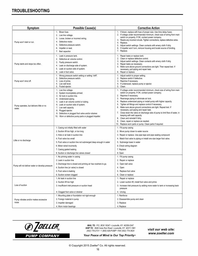
TROUBLESHOOTING
Symptom Possible Cause(s) Corrective Action
Pump won’t start or run.
1. Blown fuse.2. Low line voltage.3. Loose, broken or incorrect wiring.4. Defective motor.5. Defective pressure switch.6. Impeller or seal.7. Bad capacitor.
1. If blown, replace with fuse of proper size. Use time delay fuses.2. If voltage under recommended minimum, check size of wiring from main
switch on property. If OK, contact power company.3. Rewire any incorrect circuits. Tighten connections, replace defective wires.4. Replace.5. Adjust switch settings. Clean contacts with emery cloth if dirty.6. If impeller won’t turn, remove housing and locate source of binding.7. Replace.
Pump starts and stops too often.
1. Leak in pressure tank.2. Defective air volume control.3. Faulty pressure switch.4. Leak on discharge side of system.5. Leak on suction side of system.6. Leak in foot valve.
1. Repair leaks or replace tank.2. Clean or replace defective control.3. Adjust switch settings. Clean contacts with emery cloth if dirty.4. Repair leaks as necessary.5. Make sure above ground connections are tight. Then repeat test. If
necessary, pull piping and repair leak.6. Repair or replace.
Pump won’t shut off.
1. Wrong pressure switch setting or setting “drift”.2. Defective pressure switch.3. Loss of prime.4. Low well level.5. Fouled ejector.
1. Adjust switch to proper setting.2. Replace switch if defective.3. Reprime if necessary.4. If undersized, replace pump or ejector.5. Clean.
Pump operates, but delivers little or no water.
1. Low line voltage.2. System incompletely primed.3. Air lock in suction line.4. Undersized piping.5. Leak in air volume control or tubing.6. Leak on suction side of system.7. Low well capacity.8. Plugged ejector.9. Defective or plugged foot valve and/or strainer.
10. Worn or defective pump parts or plugged impeller.
1. If voltage under recommended minimum, check size of wiring from main switch on property. If OK, contact power company.
2. Reprime if necessary.3. Rearrange piping to eliminate air lock.4. Replace undersized piping or install pump with higher capacity.5. Tighten all fittings and replace control if necessary.6. Make sure above ground connections are tight. Repeat test. If
necessary, pull piping and repair leak.7. Close down the valve on discharge side of pump to limit flow of water, in
keeping with well capacity.8. Clean and reinstall if dirty.9. Clean, repair or replace as needed.
10. Replace worn parts or pump. Clean parts if required.
Little or no discharge
1. Casing not initially filled with water 1. Fill pump casing 2. Suction lift too high, or too long 2. Move pump closer to water source 3. Hole or air leak in suction line 3. Repair or replace. Use pipe tape and pipe sealing compound 4. Foot valve too small 4. Match foot valve to piping or install one size larger foot valve. 5. Foot valve or suction line not submerged deep enough in water 5. Submerge lower in water 6. Motor wired incorrectly 6. Check wiring diagram 7. Casing gasket leaking 7. Replace 8. Suction or discharge line valves closed 8. Open
Pump will not deliver water or develop pressure
1. No priming water in casing 1. Fill pump casing 2. Leak in suction line 2. Repair or replace 3. Discharge line is closed and priming air has nowhere to go. 3. Open ball valve 4. Suction line (or valve) is closed 4. Open 5. Foot valve is leaking 5. Replace foot valve 6. Suction screen clogged 6. Clean or replace
Loss of suction
1. Air leak in suction line 1. Repair or replace2. Suction lift too high 2. Lower suction lift, install foot valve and prime3. Insufficient inlet pressure or suction head 3. Increase inlet pressure by adding more water to tank or increasing back
pressure4. Clogged foot valve or strainer 4. Unclog
Pump vibrates and/or makes excessive noise
1. Mounting plate or foundation not rigid enough 1. Reinforce2. Foreign material in pump 2. Disassemble pump and clean3. Impeller damaged 3. Replace4. Worn motor bearings 4. Replace
MAIL TO: P.O. BOX 16347 • Louisville, KY 40256-0347SHIP TO: 3649 Cane Run Road • Louisville, KY 40211-1961
(502) 778-2731 • 1 (800) 928-PUMP • FAX (502) 774-3624
Your Peace of Mind is Our Top Priority ®
® visit our web site:www.zoeller.com