Postirradiation Examination on Innovative Advance Reactor ......The EBR-II data suggests that FGR is...
28
Luca Capriotti, Jason M. Harp* Idaho National Laboratory (*now Oak Ridge National Laboratory) Nufuel-MMSNF 2019 Workshop PSI Auditorium, Switzerland November 4-7, 2019 INL/CON-19-56301 Nuclear Technology Research and Development Postirradiation Examination on Innovative Advance Reactor Metallic Fuel Concepts
Transcript of Postirradiation Examination on Innovative Advance Reactor ......The EBR-II data suggests that FGR is...

Luca Capriotti, Jason M. Harp*
Idaho National Laboratory
(*now Oak Ridge National Laboratory)
Nufuel-MMSNF 2019 Workshop
PSI Auditorium, Switzerland
November 4-7, 2019
INL/CON-19-56301
Nuclear Technology Research and Development
Postirradiation Examination on Innovative
Advance Reactor Metallic Fuel Concepts

Contents
◼ Introduction
➢ Advance Fuel Campaign
➢ PIE strategy
➢ Metallic fuel background
◼ Advance fuel form / High burnup concepts test
➢ Recent engineering PIE results & comparison
➢ SEM preliminary results
◼ Summary & Prospective
2

NTRD Advanced Fuels Campaign
3
◼ Enhance the performance and safety of the USA current and future reactors
◼ Enhance proliferation resistance of nuclear fuel
◼ Effectively utilize nuclear energy resources
◼ Address the longer-term waste management challenges

History of the AFC Irradiations
2003 2004 2005 2006 2007 2008 2009 2010 2011 2012 2013 2014 2015 2016 2017 2018 2019
1B
1D
1F, 1G
1Æ, 1H
FUTURIX-FTA
FUTURIX-FTA
2A
2B
2C
2D
2E
3A, 3C
3B, 3D
3F
4A
4B/D
4C
4F
Future
AFC-1 36 rodlets
• non- or low-fertile compositions for
accelerators and fast reactors
• metallic and nitride fuels
• Am, Np for transmutation
• sister experiments for low and high
burnup comparison
• FUTURIX-FTA: Phénix fast reactor
experiment with select AFC-1
compositions
AFC-2 29 rodlets
• low-fertile compositions for fast
reactors
• metallic and oxide fuels
• Am, Np for transmutation
• Assume batch extraction of TRU
• RE additions to simulate recycling
carry-over
• sister experiments for low and high
burnup comparison
AFC-OA ~30 rodlets
• low-fertile compositions for fast
reactors
• metallic fuels
• innovative design features for ultra-
high burnup
• smear density, geometry, alloy,
additives, …
• short and long term tests
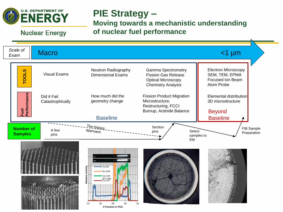
PIE Strategy –Moving towards a mechanistic understanding
of nuclear fuel performance
Scale of
Exam <1 µmMacro
TO
OL
SF
uel
Perf
orm
an
ce
Number of
Samples
Section
pinsA few
pinsSelect
samples to
EM
FIB Sample
Preparation
Visual Exams
Did it Fail
Catastrophically
How much did the
geometry change
Neutron Radiography
Dimensional Exams
Gamma Spectrometry
Fission Gas Release
Optical Microscopy
Chemistry Analysis
Fission Product Migration
Microstructure,
Restructuring, FCCI
Burnup, Actinide Balance
Electron Microscopy
SEM, TEM, EPMA
Focused Ion Beam
Atom Probe
Elemental distribution
3D microstructure
24 26 28 30 32
Rela
tive
Ac
tivit
y
Z Position in PGS
Co-60
Eu-154
Ce-144(Pr-144)Cs-137
BaselineBeyond
Baseline

Available PIE
◼ Baseline Nondestructive PIE
– visual
– neutron radiography
(thermal, epi-thermal)
– gamma scan (axial isotopic data)
– metrology (radial swelling)
◼ Baseline Destructive PIE
– fission gas analysis
– optical microscopy / metallography
– microhardness
– analytical chemistry / burnup analysis
– mechanical properties
◼ Advanced PIE
– Microstructural analysis (SEM)
– Microchemical analysis (EPMA, SEM)
– Phase analysis (pending deployment)
– Thermal properties (laser flash, TCM)
– XRD, Micro XT
– 3D Microstructure (FIB, PFIB)
– Lower scales (TEM, APT)
60.E+00
1.E+03
2.E+03
3.E+03
4.E+03
5.E+03
6.E+03
24 25 26 27 28 29 30 31 32
Rela
tive
Ac
tivit
y
Z Position in PGS
Co-60
Eu-154
Ce-144 (Pr-144)

History of Metallic Fuels in Fast Reactors
◼ EBR-I (1951)
– Unalloyed U
– U-2Zr
– Pu-1.25Al
◼ UK Dounreay Fast Reactor (1963)
– U-0.1Cr
– U-7Mo
– U-9Mo
◼ Enrico Fermi FBR (1963)
– U-10Mo
◼ EBR-II (1964)
– U-5Fs
– U-10Zr
– U-20Pu-10Zr
◼ FFTF (1982)
– Qualification of U-10Zr
– Assembly testing of U-20Pu-10Zr

Key Features & benefits of Metallic
Fuels
◼ Historic benefits
– Higher breeding ratio (fissile and fertile)
– Benign response to accident condition
– Hard neutronic spectrum
– Outstanding fuel reliability to high burnup (~20 at.%)
– Compatibility with proliferation-resistant electrochemical
recycle
– Simple, compact (demonstrated remote) fabrication
processes
– Synergistic with passive approach to reactor safety
◼ Metal fuel characteristics
– U-Pu-Zr alloy base (good irradiation stability)
– 75% smeared density (accommodate fuel swelling, mitigate
FCMI)
– Large fission gas plenum (accommodate high gas release)
– Na bond in fuel-cladding gap (keep fuel temperatures low)
– Low-swelling FMS cladding (minimize cladding/duct
dimensional changes) 39,000 EBR-II pins
fabricated remotely in
1960’s
Schematic of a metallic, Na bonded, fast reactor element
Carmack et al., J. Nucl. Mater. 392 (2009)
G.L Hofman and L. C. Walters, "Metallic
Fast Reactor Fuels," Materials Science
and Technology Vol. 10A, 1994.

Fast Reactor Fuel Performance Challenges
& New Concepts
◼ Historical Fuel Performance Issues
– Swelling - limited burnup to 3 at. %, Solved early in EBR-II testing
with lowering Smeared Density to 75% to allow for interconnected
porosity releasing fission gas, solid fission product build-up limits
fuel to 15-20 at.% burnup
– Alloying elements to raise the fuel melting temperature and tailor
the phase of U or U+Pu in the fuel (Zr, Fs, Mo, Ti)
– Fuel Cladding Chemical Interaction (FCCI)
• FCCI occurs at nominal operating conditions in U and U-Mo fuels and
limits burnup to 10at. % (U-Fe, U-Ni interaction typically)
• FCCI occurs at nominal operation conditions in U-Zr and U-Pu-Zr fuels
beyond 10at.% burnup (Lanthanide – Fe interaction typically)
– Fuel Constituent Redistribution – an effect of phase transitions
• U, U-5Fs, and U-10Mo do not redistribute
• U-10Zr does redistributes where Zr migrates to the center of the fuel
• U-Pu-10Zr redistributes with Zr migrating to the central region and the
periphery
9
Annular / low
smear density
New alloys
Additives
New alloys
New concepts
Fs – 49.8Mo-38Ru-6Rh-4Pd-2Zr-0.2Nb

Fast Reactor Testing in ATR –
Recent AFC tests
◼ Testing Fast Reactor Fuels in a
thermal reactor
– Rodlet – capsule – Cd basket system
– Comparison between true fast
spectrum vs ATR irradiations: proper
temperature profile is created in ATR
irradiations
– This allows for the study of fuel
performance phenomena that are
primarily dependent upon temp. /
temp. gradient
Typical AFC-3 Rodlet cross section
0.4
0.6
0.8
1
1.2
1.4
1.6
1.8
2
2.2
2.4
0 0.2 0.4 0.6 0.8 1
Po
we
r fa
cto
r
r/r0
Unshrouded
SFR
Cd-shrouded

AFC-3 A/B/C/D and AFC-4A series
◼ AFC-3A/B/C/D and AFC-4A is an alloy exploration test– Alternate alloys and forms to U-10Zr,
Sodium Bonded, 75% SD
– Pd additive to mitigate FCCI
– Annular Forms to eliminate Na treatment issues
◼ Meant to test early alloy performance against the historical experience
◼ Irradiation Issues– Capsule Fabrication 3A/B
– Reactor Uncertainty
11
Rodlet ID AlloyFuel
Form
Bond
Material
Nominal
Smear
Density
3C-R1 U-10Mo Solid Sodium 75%
3C-R2 U-10Mo Annular Helium 55%
3C-R3 U-10Zr Sodium Solid 65%
3C-R4 U-10Zr Annular Helium 55%
3C-R5A U-1Pd-13Zr Solid Sodium 75%
3C-R5B U-2Pd-13Zr Solid Sodium 75%
3D-R1 U-10Zr Annular Helium 55%
3D-R2 U-4Pd-13Zr Solid Sodium 55%
3D-R3 U-10Mo Solid Sodium 55%
3D-R4 U-10Mo Annular Helium 55%
3D-R5 U-4Pd-13Zr Annular Helium 55%
4A-R1 U-10Mo Annular Helium 65%
4A-R3 U-5Mo-4.3Ti-0.7Zr Solid Sodium 75%
4A-R4U-5Mo-4.3Ti-0.7Zr-
2PdSolid Sodium 75%
4A-R5 U-10Zr Solid Sodium 75%
Rodlet ID AlloyFuel
Form
Bond
Material
Nominal
Smear
Density
3A-R1 U-10Mo Solid Sodium 75%
3A-R2 U-10Mo Annular Helium 55%
3A-R4 U-10Zr Annular Helium 55%
3A-R5A U-1Pd-10Zr Solid Sodium 75%
3A-R5B U-2Pd-10Zr Solid Sodium 75%
3B-R1 U-4Pd-10Zr Solid Sodium 55%
3B-R2 U-4Pd-10Zr Annular Helium 55%
3B-R4 U-10Mo Solid Sodium 55%
3B-R5 U-10Mo Solid Sodium 55%

AFC-3C/3D –Irradiation History
◼ AFC-3C had irradiation temperature
– Peak Inner Cladding Temperature (PICT) exceeded 600°C for 3 or 4 rodlets
– PICT in R1 and R5 likely exceeded 650°C
– Experiment removed from ATR early after 3 cycles
◼ AFC-3D had reasonable PICT temperatures and appears to have better performance
540
560
580
600
620
640
660
680
700
0 20 40 60 80 100 120
PIC
T (°
C)
EFPD
3C-1
3C-2
3C-3
3C-4
3C-5A
3C-5B
500
520
540
560
580
600
620
640
0 50 100 150 200
PIC
T 9
°C)
EFPD
3D-1
3D-2
3D-3
3D-4
3D-5
Rodlet
Diameter
0.230 inch
Capsule Inner
Diameter .234±.001 in
Most Capsules are
near 0.235 inches

AFC-3C/3D – NDE highlights
5825
5845
5865
5885
5905
5925
5945
0 20 40 60 80 100 120 140 160
Dia
met
er (
µm
)
Distance from top of rodlet (mm)
Average AFC-3C R1
AFC-3C R2 Average
AFC-3C R3 Average
AFC-3C R4 Average
Average AFC-3C R5
Capsule Inner WallDiameterAFC-3D R1 Average
AFC-3D R2 Average
AFC-3D R3 Average
Rod Outer Diameter Range
AFC-3C R4
AFC-3C R5
AF
C-3
C R
4
AF
C-3
C R
5
AF
C-3
C R
3
AF
C-3
C R
2
AF
C-3
C R
1
AF
C-3
D R
4
AF
C-3
D R
5
AF
C-3
D R
3
AF
C-3
D R
2
AF
C-3
D R
1
◼ Thermal neutron radiography
– Annular fuel pins (e.g. 3C-R4)
maintained their annuli
– Visible change in grey scales shows
variation in density
◼ Profilometry
– AFC-3C presents some degree of
diametrical strain (max 0.7% strain)
– AFC-3D no measurable change in
diameter

AFC 3C/D - Fission Product
Distribution
14
◼ Axial Gamma spectrometry
– RhRu-106 flat distribution
– Annular fuel: Cs migrates
towards cooler axial ends
– Ce-144 some axial migration
0
50000
100000
150000
200000
250000
300000
0 5 10 15
Rel
ativ
e A
ctiv
ity
Distance from bottom of Rodlet (cm)
Cs-137
RuRh-106
CePr-144
Mn-54
Eu-154
0
20000
40000
60000
80000
100000
120000
140000
0 2 4 6 8 10 12 14
Rel
ativ
e A
ctiv
ity
Distance from bottom of Rodlet (cm)
Cs-137
RuRh-106
CePr-144
Mn-54

AFC 3C/D - Fission Product
Distribution
15
◼ Gamma Emission Tomography reveals the transverse distribution of fission products
◼ Signals exist for most major types of fission products
AF
C-3
C R
3A
FC
-D R
1
Cs-137 Ru-106 CePr-144U-10Zr 65% SD, solid
U-10Zr 55% SD, annular

Fission Gas Release
16
◼ The EBR-II data suggests that FGR is 70±10% after 1.5x10²¹ fiss/cc (~4 at.%)
◼ Other AFC tests and transmutation fuel (FUTURIX) tests also follow this general
trend
◼ The AFC-3 tests often also follow this trend
– There is some evidence that low smear density, annular fuel, and U-Mo fuel release fission
gas earlier
0%
10%
20%
30%
40%
50%
60%
70%
80%
90%
100%
0 5E+20 1E+21 1.5E+21 2E+21 2.5E+21 3E+21 3.5E+21 4E+21 4.5E+21 5E+21 5.5E+21 6E+21 6.5E+21 7E+21
FGR
Fission density
Fission Gas release vs Fission density
EBR-II
AFC-1
FUTURIX
AFC-3

AFC 3C / 3D U-Mo Metallography
1717
AFC-3C R1 (U-10Mo,
75% SD, solid, Na, 2.3%FIMA, 650°C)
AFC-3C R2 (U-10Mo,
55% SD, annular, He, 3.3%FIMA, 625°C)
AFC-3D R3 (U-10Mo,
55% SD, solid, Na, 2.1%FIMA , 625°C)
AFC-3D R4 (U-10Mo, 55%
SD, annular, He, 4.5%FIMA, 600°C)

AFC 3C / 3D U-Zr solid
Metallography
AFC-3C R3 (U-10Zr,
65% SD, solid, Na, 2.9%FIMA, 630°C)
AFC-3D R2 (U-4Pd-
13Zr, 55% SD, solid, Na, 2.8%FIMA, 630°C)
AFC-3C R5A (U-1Pd-
13Zr, 75% SD, solid, Na, 2.6%FIMA, 680°C)
AFC-3C R5B (U-2Pd-13Zr, 75% SD, solid, Na, 2.6%FIMA, 660°C)
Fuel Mid-plane Fuel Top

AFC 3C / 3D U-Zr annular
Metallography
19AFC-3D R1 (U-10Zr, 55% SD, annular, He, 4.3%FIMA, 600°C)
AFC-3C R4 (U-10Zr,
55% SD, annular, He, 3.0%FIMA, 620°C)
AFC-3D R5 (U-4Pd-
13Zr, 55% SD, annular, He, 2.9%FIMA, 610°C)

AFC 3C / 3D U-Zr annular
Metallography
◼ Two of the Annular
U-Zr variants
performed
exceptionally well
◼ Two contributing
factors
– Appropriate PICT at
all times during
irradiation
– Well machined fuel
slugs
20

U-10Zr prelim. comparison between
AFC-series
21
U-10Zr,
annular, 55% sd
AFC-3DAFC-3CAFC-3A R4*
◼ U-10Zr annular: AFC-3D behaves better compare to -3A-3C
– Machining, gap ~50µm AFC-3A R4 vs 17µm AFC-3C R4 177ºC vs 60ºC
– Periphery temperature maintained below the critical temperature for Zr migration (Beta phase)
*AFC-3A: U-10Zr, bu 3.2 at.%, PICT 530°C / U-1/2Pd-10Zr, bu 2.5 at.%, PICT 585°C
AFC-3B R2*
U-4Pd-10/13Zr,
annular, 55% sd

SEM preliminary results
◼ AFC-3A/B/C/D electron microscopy examination– Challenges to prepare samples (high dose)
– A more quantitative understanding of the different phases and feature is required• New additives work?
• FCCI
• Temp / gap effect
22
Rodlet ID AlloyFuel
Form
Bond
Material
Nominal
Smear
Density
3C-R1 U-10Mo Solid Sodium 75%
3C-R2 U-10Mo Annular Helium 55%
3C-R3 U-10Zr Sodium Solid 65%
3C-R4 U-10Zr Annular Helium 55%
3C-R5A U-1Pd-13Zr Solid Sodium 75%
3C-R5B U-2Pd-13Zr Solid Sodium 75%
3D-R1 U-10Zr Annular Helium 55%
3D-R2 U-4Pd-13Zr Solid Sodium 55%
3D-R3 U-10Mo Solid Sodium 55%
3D-R4 U-10Mo Annular Helium 55%
3D-R5 U-4Pd-13Zr Annular Helium 55%
Rodlet ID AlloyFuel
Form
Bond
Material
Nominal
Smear
Density
3A-R1 U-10Mo Solid Sodium 75%
3A-R2 U-10Mo Annular Helium 55%
3A-R4 U-10Zr Annular Helium 55%
3A-R5A U-1Pd-10Zr Solid Sodium 75%
3A-R5B U-2Pd-10Zr Solid Sodium 75%
3B-R1 U-4Pd-10Zr Solid Sodium 55%
3B-R2 U-4Pd-10Zr Annular Helium 55%
3B-R4 U-10Mo Solid Sodium 55%
3B-R5 U-10Mo Solid Sodium 55%

AFC-3A R5 SEM (U-2Pd-10Zr) –
Alloying Element Behavior
◼The behavior of Zr and Pd are important
for this fuel to well perform
– Zr needs to stayed alloyed with U for fuel
performance
– Zr and Pd intermetallics need to be avoided
– Pd needs to form intermetallics with
Lanthanides (LnPd and Ln7Pd3)
– Alloy addition steps are important
U
Zr
Pd
Nd

AFC-3B R2 SEM (U-4Pd-10Zr) –
FCCI – Alloying behavior
◼ FCCI occurred in this sample similar to the
same levels observed in U-Mo
◼ Too much Pd can be detrimental to fuel
performance
– Pd and Zr will form high temperature intermetallics
leaving U unalloyed (PdZr2)
– Pd alloying addition order can significantly change
as-cast intermetallic behavior (understood after this
irradiation was fabricated)
◼ Cast annular fuel without a Na bond is
susceptible to local overheating Cu tape
Cladding
Pd, Zr, Fe
U only
Pd, Zr, Fe
U only
U, Fe mix (U6Fe)
U, Fe mix (UFe2)
Zr band
Original ID

AFC-3A R4 SEM (U-10Zr annular) –
FCCI - Helium gap effect
25
BSE Zr
Fe UAFC-3A R4 (U-10Zr, 55% SD, annular, He, 3.3%FIMA, 540-600+°C)

Summary & Prospective
26
◼ Advanced metallic fuel form
– Raise from the needs to elevate utilization and reach higher burnup
– Improve historical issue of metallic fuel
◼ AFC-3 and -4 experiments
– Alloys exploration test (annular, alternative alloys, additives)
– Some promising design and value data are examined for the first time
– U-Mo performance are quite below U-Zr
– Annual fuel (well machined) and Pd additives fuel form are somehow promosing
◼ Future and Prospective
– Extended examination are needed (also supported by modelling and simulation)
– Extended burnup / experiment on some promising fuel form are needed
– Safety / transient test on promising fuel from are the natural next step

Irradiated Material Characterization
Laboratory (2019-2020)
27Come work with us!

Contributors
◼ Doug Porter
◼ Steve Hayes
◼ Heather Chichester
◼ HFEF Staff
– Colt Killian
– Katelyn Wachs
– John Stanek
– Dave Sell
– Glen Papaioannou
– Francine Rice
– HFEF Operators
◼ AL Staff
– Jeff Giglio
– Dan Cummings
– Mike Rodriquez
– Brian Storms
– Larry Fulkrod
◼ IMCL/EML Staff
– Alex Winston
– Nick Bolender
– Brandon Miller
– Tammy Trowbridge
– Jim Madden
– Karen Wright
◼ And others