Post Tree Protection Barrier (See Note #4) · Install trunk protection when Tree Protection Barrier...
13
In The Plans Unless Otherwise Indicated The Tree Protection Barrier Maintain Existing Grade Within To Hold Barrier Taut Secure Barrier To Posts Orange Construction Barrier Crown Dripline Of The Tree No Open Trenching Under The X" X' (See Note #7) Weather Resistant Sign 4' Minimum Barrier Height Underground Utility 4' Minimum Depth Burlap Bands Tree 2" XC 4" Boards Or To Lowest Branch 6' Minimum Height Post Tree Trunk Crown Dripline Tree Trunk Crown Dripline Dripline Of The Tree Outside Of The Crown Trenching May Occur Crown Dripline Protection Zone Crown Dripline (See Plans For Barrier Alignment) Tree Protection Barrier See Note #1 Post (See Note #4) Barrier Protection Tree The Trunk Boards And Between The Place Burlap Bands (3 Minimum) Boards Into Tree) (Do Not Fasten Protective Barrier Form A Continuous 2" x 4" Boards To To Maintain Taut Barrier Install At Depth Sufficient 10/ 23/ 2017 10: 24: 06 AM REVI SI ON DESCRIPTION: REVISION LAST of STANDARD PLANS FY 2018-19 SHEET INDEX 11/01/17 TREE PROTECTION AND PRESERVATION 110-100 1 1 TRUNK PROTECTION TREE PROTECTION BARRIER ELEVATION ELEVATION PLAN SECTION A-A PLAN A A AREA TREE PROTECTION KEEP OUT PROTECTION BARRIER FOR TREE GROUPINGS on this Index. may be used in lieu of the tree pretection barrier detailed 8. Alternate tree protection systems approved by the Engineer Spanish. Sign should read " Keep Out Tree Protection Area". with 6" minimum text height and provide text in English and 7. Place weather resistant sign every 50' along the barrier, within the tree protection area. 6. See plans for any additional requirements or modifications girdling. Adjust bands to allow tree growth as needed. 5. Inspect trunk protection and tree quarterly to prevent protection barrier around the entire group. 4. For closely spaced groups of trees, place the tree Maintain protection at all times. construction and remove when directed by the engineer. 3. Install all tree protection prior to commencement of protection barrier, including during barrier installation. equipment is not permitted within the limits of the tree 2. Staging, storage, dumping, washing and operation of inch of trunk diameter at breast height. from trunk of tree to a distance equal to one foot per 1. Crown Dripline Protection Zone: Extends in all directions NOTES: 3. Adjust bands to allow tree growth (inspect quarterly to prevent girdling). 2. See Selective Clearing and Grubbing Plan for location of trunk protection. 1. Install trunk protection when Tree Protection Barrier can not be reasonably erected. NOTES:
Transcript of Post Tree Protection Barrier (See Note #4) · Install trunk protection when Tree Protection Barrier...

In The Plans
Unless Otherwise Indicated
The Tree Protection Barrier
Maintain Existing Grade Within
To Hold Barrier Taut
Secure Barrier To Posts
Orange Construction Barrier
Crown Dripline Of The TreeNo Open Trenching Under The
X" X'
(See Note #7)
Weather Resistant Sign
4' Minimum Barrier Height
Underground Utility
4' Minimum Depth
Burlap
Bands
Tree
2" XC 4" Boards
Or To Lowest Branch
6' Minimum Height
Post
Tree Trunk
Crown Dripline
Tree TrunkCrown Dripline
Dripline Of The Tree
Outside Of The Crown
Trenching May Occur
Crown Dripline Protection Zone
Crown Dripline (See Plans For Barrier Alignment)
Tree Protection Barrier
See Note #1
Post
(See Note #4)
Barrier
Protection
Tree
The Trunk
Boards And
Between The
Place Burlap
Bands (3 Minimum)
Boards Into Tree)
(Do Not Fasten
Protective Barrier
Form A Continuous
2" x 4" Boards To
To Maintain Taut Barrier
Install At Depth Sufficient
10/23/2017
10:2
4:0
6
AM
RE
VISIO
N DESCRIPTION:
REVISION
LAST
ofSTANDARD PLANS
FY 2018-19 SHEETINDEX
11/01/17TREE PROTECTION AND PRESERVATION
110-100 1 1
TRUNK PROTECTIONTREE PROTECTION BARRIER
ELEVATION
ELEVATION
PLAN
SECTION A-A
PLAN
A A
AREA
TREE PROTECTION
KEEP OUT
PROTECTION BARRIER FOR TREE GROUPINGS
on this Index.
may be used in lieu of the tree pretection barrier detailed
8. Alternate tree protection systems approved by the Engineer
Spanish. Sign should read " Keep Out Tree Protection Area".
with 6" minimum text height and provide text in English and
7. Place weather resistant sign every 50' along the barrier,
within the tree protection area.
6. See plans for any additional requirements or modifications
girdling. Adjust bands to allow tree growth as needed.
5. Inspect trunk protection and tree quarterly to prevent
protection barrier around the entire group.
4. For closely spaced groups of trees, place the tree
Maintain protection at all times.
construction and remove when directed by the engineer.
3. Install all tree protection prior to commencement of
protection barrier, including during barrier installation.
equipment is not permitted within the limits of the tree
2. Staging, storage, dumping, washing and operation of
inch of trunk diameter at breast height.
from trunk of tree to a distance equal to one foot per
1. Crown Dripline Protection Zone: Extends in all directions
NOTES:
3. Adjust bands to allow tree growth (inspect quarterly to prevent girdling).
2. See Selective Clearing and Grubbing Plan for location of trunk protection.
1. Install trunk protection when Tree Protection Barrier can not be reasonably erected.
NOTES:

10/23/2017
10:2
4:0
7
AM
RE
VISIO
N DESCRIPTION:
REVISION
LAST
ofSTANDARD PLANS
FY 2018-19 SHEETINDEX
11/01/17MAILBOXES
110-200 1 3
GENERAL NOTES
installation, resetting or relocation.
There shall be no payment participation for NDCBU furnishing, assembly,
contractor for removal and disposal of existing mailboxes.
The above compensation shall include any work and cost incurred by the
arrangement.
mailbox regardless of the number of mailboxes per support or grouping
mailbox is new, reused, salvaged, reset or relocated. Payment shall be per
Payment shall be limited to one mailbox per patron address whether the
numbers.
adjustments to suit construction needs; and, for identification letters and
essential for installation in accordance with this standard; erection;
Payment shall be full compensation for boxes, posts and accessory items
Mailboxes shall be paid for under the contract unit price for Mailboxes, Each. 12.
finishes are to be suited to support post finish.
Mounting brackets, plates, platforms, shelves and accessory hardware surface
required.
approved by the Engineer. When galvanized posts are used painting is not
prefers that posts be painted white, but other colors may be used when
shall be cleaned of all loose scale prior to finishing. The Postal Service
coats of weather resistant, air dried or baked, paint or enamel. Surface(s)
Steel support posts shall have an external finish equal to or better than two
the Standard Specifications.
requirements of Section 952 and the treatment requirements of Section 955 of
Wood support posts shall be in conformance with the material and dimensional 11.
exceeds 400 vehicles per day.
delivery route, with the distance increased to 200' when the route volume
centerline of the intersecting road on the far side in the direction of the
At intersecting roads mailboxes shall be located 100' or more from the
driveway in the direction of the delivery route.
At driveway entrances mailboxes shall be placed on the far side of the 10.
Support posts shall not be fitted nor installed with surface mount base plates.
material.
shall be separated from the pavement by a minimum of 1" of expansion
support posts are set within rigid pavement back of curb, the support posts
mailboxes on rural highways. On urban roads and streets where mailbox
either above or below the shoulder groundline, will not be permitted for
Concrete, block, brick, stone or other rigid foundation structure or encasement,
shall be embedded no more than 24" into the ground.
Wood and steel support posts for both single and double mailbox mountings 9.
maintenance.
The mail patron shall be responsible for newspaper receptacle installation and
side of the support post in conformance with the USPS Domestic Mail Manual.
Lightweight newspaper receptacles may be mounted below the mailbox on the 8.
Postmaster for the delivery route under consideration.
clear zones. The location of NDCBUs is the sole responsibility of the
multiple mailbox installation that must be located outside the highway and street
Neighborhood Delivery and Collection Box Units (NDCBU) are a specialized
crash testing in accordance with NCHRP Report 350.
support structure and mailbox arrangements have been shown to be safe by
No more than two mailboxes may be mounted on a support structure unless the 7.
restrictions.
mail stop surface, unless the U.S. Postal Service establishes other height
Mailboxes shall be set with the bottom of the box between 42" and 48" above the 6.
the sidewalk, where they can be served by the carrier from the sidewalk.
postal authority, may be permitted to install all mailboxes at the back edge of
install or serve boxes at the curb, the Contractor, with concurrence of the local
curb or if an unusual condition exists which makes it difficult or impractical to
the box between 6" and 12" behind the face of curb. If the sidewalk abuts the
Mailboxes on curbed highways, roads, and streets shall be set with the face of
behind the guardrail whenever practical.
When a mailbox is installed within the limits of guardrail it should be placed
2'-6" for low speed and ADT under 100 vpd.
6' for ADT under 100 vpd
8' for ADT 100 to 10,000 vpd.
10' for ADT over 10,000 vpd.b.
Shoulder width plus 8" to 12".a.
the following:
offset from the edge of the traveled way a minimum distance of the greater of
Mailboxes on rural highways shall be set with the roadside face of the box
may be placed on the left-hand side.
direction of the delivery route, except on one-way roads and streets where they
Mailboxes shall be located on the right-hand side of the roadway in the 5.
Headquarters, Washington, DC 20260.
Rural Delivery Division, Delivery Service Department, Operations Group, USPS
of mailboxes, design approval and guidance may be obtained by writing to the
Mailbox production standards, lists of approved manufacturers and suppliers
Postal Service (DMM).
only, and only in Size 1 as prescribed by the Domestic Mail Manual of the U. S.
Mailboxes shall be light sheet metal or plastic construction, in traditional style 4.
the Engineer.
constructing a new mailbox. Any use of existing mailboxes must be approved by
Contractor at his option may elect to reuse the existing mailbox in lieu of
requirements of this Index and is structurally and functionally sound, the
any construction project; however where an existing mailbox meets the design
Reuse of existing mailboxes by the Contractor will not be a requirement under
dispose of mailboxes and supports in areas provided by him.
included in the contract unit price for Mailbox, Each. The Contractor shall
place for removal by the Contractor; removal by the Contractor shall be
the option of removing their existing mailboxes or leaving the mailboxes in
must be accomplished in 21 days after receipt of notices. Patrons shall have
"Mail Delivery Patron" by Certified Mail that removal of the existing mailboxes
Immediately after installing the new mailboxes the Contractor must notify each
The Contractor shall coordinate removal of the patrons existing mailboxes.
name and house number on the box.
street from the patrons residence, the Contractor shall inscribe the street
inscribe the house number on the box; if the box is located on a different
authorized by the Postmaster as a postal address, the Contractor shall
the U. S. Postal Service; where local street names and house numbers are
accordance with identification specifications of the Domestics Mail Manual of
contract period. The Contractor shall apply box numbers to each patron box in
Index at each mail patron delivery location and maintain the box throughout the
The Contractor shall furnish and install one mailbox in accordance with this
Sundays and Holidays excluded.
of project construction 7 days prior to the beginning of work, with Saturdays,
The contractor shall give the Postmaster of the delivery route(s) written notice 3.
highways where prohibited by law or regulation.
Mailboxes will not be permitted on Interstate highways, freeways, or other 2.
regulations of the United States Postal Service as modified by this Index.
The location and construction of mailboxes shall conform to the rules and 1.
10/23/2017
10:2
4:0
8
AM
RE
VISIO
N DESCRIPTION:
REVISION
LAST
ofSTANDARD PLANS
FY 2018-19 SHEETINDEX
11/01/17MAILBOXES
110-200 2 3
Platform
1 Nut, 1 Spacer (12 Reqd.)
2 Washers, 1 Lockwasher,
" Hex Bolt43"-18 x 116
5
Adapter Plate
For Finish Requirements
See General Notes
Flanged Channel
2 Lb. Per Foot
1 Lockwasher, 1 Nut (10 Reqd.)
(Stove Bolt) 2 Washers,
" Slotted Rd. Hd. Bolt43#8-32 x
Platform
Bracket
1 Nut (3 Reqd.)
2 Washers, 1 Lockwasher,
" Hex Bolt,41"-18 x 216
5
Bracket
Platform
1 Nut (4 Reqd.)
2 Washers, 1 Lockwasher,
" Hex Bolt,43"-16 x 16
5
For Finish Requirements
See General Notes
Flanged Channel
2 Lb. Per FootBracket
1 Nut (3 Reqd.)
2 Washers, 1 Lockwasher,
" Hex Bolt,41"-18 x 216
5
Platform
1 Lockwasher, 1 Nut (10 Reqd.)
(Stove Bolt) 2 Washers,
" Slotted Rd. Hd. Bolt43#8-32 x
Line
Ground
1"x3" Slots (4 Reqd.)
" Dia.871
"41"x18
3
(10 Reqd.)
" Slots161" x 116
3
(3 Holes)
" Diameter83
" Slots (4 Reqd.)83"x18
3
Std. Wt. Pipe
"21Nominal
" For Brackets1651
" For Platforms43
ELEVATION
POST SPACING
SIDE VIEW
FLANGED CHANNEL
FRONT VIEWSIDE VIEW
FLANGED CHANNEL
FRONT VIEW
BOTTOM VIEW
END VIEW
STEEL PLATFORM
SIDE VIEW
FRONT VIEW END VIEW
TOP VIEW
STEEL BRACKET
STEEL SPACER
END VIEW
STEEL ADAPTER PLATE
TOP VIEW
STEEL FLANGED CHANNEL SUPPORT POSTS
OR PIPE POST TYPES SHOWN ON THIS INDEX
SINGLE OR COMBINED WOOD, FLANGED CHANNEL
Note: See General Notes for finish requirements.
Depth
24"
Max.
Notes
See
General
h=
42" to 48"
h (Min.)43 h (Min.)4
3
4""412"4
124"
2"
"323
"217
15"
4"
6"
3"
3"
9"
"214 "2
14
"412 "4
12
"212 "2
12
"16
13
1
"16
13
1
"16
12
"16
12 "16
1
"431 "4
31 "431 "4
31 "8
3
"16
13
"2
1
3"
3"
2"
"323
"211
1"
1"
10/23/2017
10:2
4:0
8
AM
RE
VISIO
N DESCRIPTION:
REVISION
LAST
ofSTANDARD PLANS
FY 2018-19 SHEETINDEX
11/01/17MAILBOXES
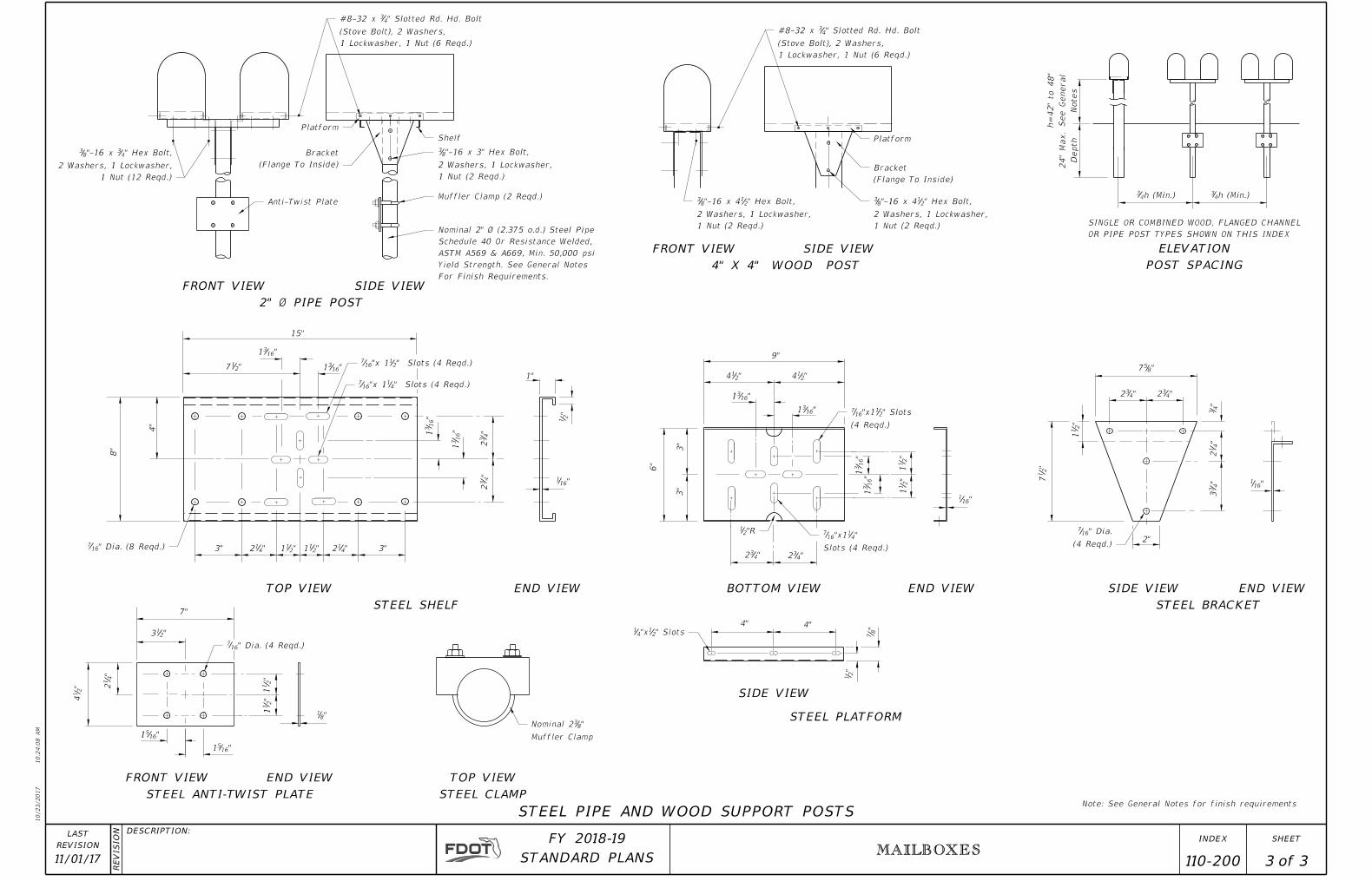
110-200 3 3
1 Nut (12 Reqd.)
2 Washers, 1 Lockwasher,
" Hex Bolt,43"-16 x 8
3
Anti-Twist Plate
(Flange To Inside)
Bracket
Platform
Shelf
1 Nut (2 Reqd.)
2 Washers, 1 Lockwasher,
"-16 x 3" Hex Bolt,83
Muffler Clamp (2 Reqd.)
For Finish Requirements.
Yield Strength. See General Notes
ASTM A569 & A669, Min. 50,000 psi
Schedule 40 Or Resistance Welded,
Nominal 2" Ø (2.375 o.d.) Steel Pipe
1 Lockwasher, 1 Nut (6 Reqd.)
(Stove Bolt), 2 Washers,
" Slotted Rd. Hd. Bolt43#8-32 x
1 Lockwasher, 1 Nut (6 Reqd.)
(Stove Bolt), 2 Washers,
" Slotted Rd. Hd. Bolt43#8-32 x
Platform
(Flange To Inside)
Bracket
1 Nut (2 Reqd.)
2 Washers, 1 Lockwasher,
" Hex Bolt,21"-16 x 48
3
1 Nut (2 Reqd.)
2 Washers, 1 Lockwasher,
" Hex Bolt,21"-16 x 48
3
" Dia. (8 Reqd.)167
" Slots (4 Reqd.)41"x 116
7
" Slots (4 Reqd.)21"x 116
7
" Dia. (4 Reqd.)167
Muffler Clamp
"83Nominal 2
" Slots21"x4
1
(4 Reqd.)
" Slots21"x116
7
Slots (4 Reqd.)
"41"x116
7"R21
(4 Reqd.)
" Dia.167
FRONT VIEW
2" Ø PIPE POST
SIDE VIEW
FRONT VIEW
4" X 4" WOOD POST
SIDE VIEW ELEVATION
POST SPACING
END VIEW
STEEL BRACKET
SIDE VIEWEND VIEWBOTTOM VIEW
SIDE VIEW
STEEL PLATFORM
STEEL CLAMP
TOP VIEW
STEEL ANTI-TWIST PLATE
END VIEWFRONT VIEW
STEEL SHELF
TOP VIEW END VIEW
STEEL PIPE AND WOOD SUPPORT POSTS
15"
"1631
"217 "16
31
8"
4"
3" "412 "2
11 "211 "4
12 3"
"4
3 2
"4
3 2
"16
3 1
"16
3 1
"161
"2
1
1"
7"
"213
"4
12"
21
4 "2
11
"2
11
"81
"1651
"2
1
"8
7
4"4"
"1631
"214
9"
"214
"1631
"16
31
"2
11
"2
11
"16
31
"161
"432"4
32
3"
3"
6"
"857
"432 "4
32
"4
3"
41
2"
43
3
"161
2"
"2
17
"2
11
h (Min.)43 h (Min.)4
3
Notes
See
General
h=
42" to 48"
Depth
24"
Max.
OR PIPE POST TYPES SHOWN ON THIS INDEX
SINGLE OR COMBINED WOOD, FLANGED CHANNEL
"1651
Note: See General Notes for finish requirements
10/23/2017
10:2
4:0
8
AM
RE
VISIO
N DESCRIPTION:
REVISION
LAST
ofSTANDARD PLANS
FY 2018-19 SHEETINDEX
11/01/17EMBANKMENT UTILIZATION
120-001 1 4
Bottom Of Base
LBR 40
Type B Stabilization
Fill Is Placed
Water Level At Time
�
� �
Water Level At Time Fill Is Placed
Bottom Of Base Type B Stabilization LBR 40 Bottom Of Base
2.5' Std.
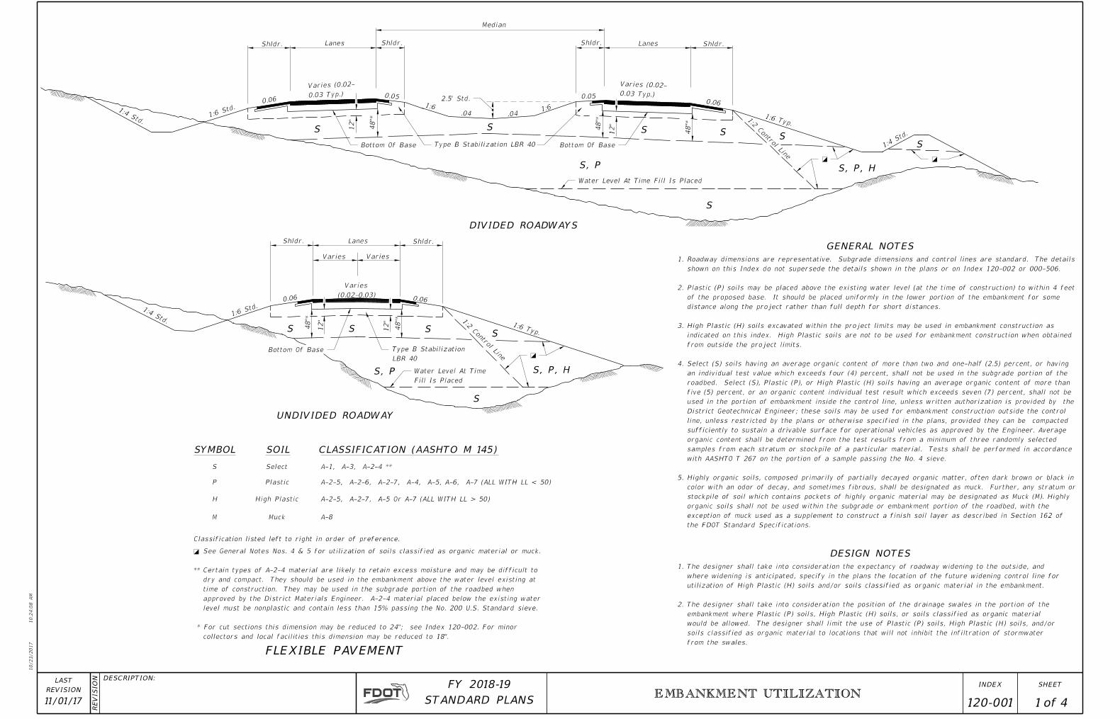
GENERAL NOTES
DESIGN NOTES
SYMBOL SOIL CLASSIFICATION (AASHTO M 145)
UNDIVIDED ROADWAY
DIVIDED ROADWAYS
S S S SS
S, P, H
S
S
S, P
S
S, P, H S, P
SSS
S
from the swales.
soils classified as organic material to locations that will not inhibit the infiltration of stormwater
would be allowed. The designer shall limit the use of Plastic (P) soils, High Plastic (H) soils, and/or
embankment where Plastic (P) soils, High Plastic (H) soils, or soils classified as organic material
The designer shall take into consideration the position of the drainage swales in the portion of the 2.
utilization of High Plastic (H) soils and/or soils classified as organic material in the embankment.
where widening is anticipated, specify in the plans the location of the future widening control line for
The designer shall take into consideration the expectancy of roadway widening to the outside, and 1.
Classification listed left to right in order of preference.
collectors and local facilities this dimension may be reduced to 18".
* For cut sections this dimension may be reduced to 24"; see Index 120-002. For minor
level must be nonplastic and contain less than 15% passing the No. 200 U.S. Standard sieve.
approved by the District Materials Engineer. A-2-4 material placed below the existing water
time of construction. They may be used in the subgrade portion of the roadbed when
dry and compact. They should be used in the embankment above the water level existing at
Certain types of A-2-4 material are likely to retain excess moisture and may be difficult to **
See General Notes Nos. 4 & 5 for utilization of soils classified as organic material or muck.�
S
P
H
M Muck
High Plastic
Plastic
Select
A-2-5, A-2-6, A-2-7, A-4, A-5, A-6, A-7 (ALL WITH LL < 50)
A-2-5, A-2-7, A-5 Or A-7 (ALL WITH LL > 50)
A-8
A-1, A-3, A-2-4 **
FLEXIBLE PAVEMENT
1:2 C
ontrol Lin
e
0.06 0.06
48"*
12"
12"
48"*
Shldr. Lanes Shldr.
VariesVaries
1:4 Std.
1:6 St
d.
1:6 Typ.
Shldr. Lanes Shldr.
Median
0.03 Typ.)
Varies (0.02-
0.06 0.05
1:6
.04 .04 1:6
12"
48"*
48"*
12"
48"*
0.06
0.05 0.03 Typ.)
Varies (0.02-
Shldr. Lanes Shldr.
1:4
Std.
1:2 C
ontrol Lin
e
1:6 Typ.
1:6 St
d.1:4 Std.
(0.02-0.03)
Varies
the FDOT Standard Specifications.
exception of muck used as a supplement to construct a finish soil layer as described in Section 162 of
organic soils shall not be used within the subgrade or embankment portion of the roadbed, with the
stockpile of soil which contains pockets of highly organic material may be designated as Muck (M). Highly
color with an odor of decay, and sometimes fibrous, shall be designated as muck. Further, any stratum or
Highly organic soils, composed primarily of partially decayed organic matter, often dark brown or black in 5.
with AASHTO T 267 on the portion of a sample passing the No. 4 sieve.
samples from each stratum or stockpile of a particular material. Tests shall be performed in accordance
organic content shall be determined from the test results from a minimum of three randomly selected
sufficiently to sustain a drivable surface for operational vehicles as approved by the Engineer. Average
line, unless restricted by the plans or otherwise specified in the plans, provided they can be compacted
District Geotechnical Engineer; these soils may be used for embankment construction outside the control
used in the portion of embankment inside the control line, unless written authorization is provided by the
five (5) percent, or an organic content individual test result which exceeds seven (7) percent, shall not be
roadbed. Select (S), Plastic (P), or High Plastic (H) soils having an average organic content of more than
an individual test value which exceeds four (4) percent, shall not be used in the subgrade portion of the
Select (S) soils having an average organic content of more than two and one-half (2.5) percent, or having 4.
from outside the project limits.
indicated on this index. High Plastic soils are not to be used for embankment construction when obtained
High Plastic (H) soils excavated within the project limits may be used in embankment construction as 3.
distance along the project rather than full depth for short distances.
of the proposed base. It should be placed uniformly in the lower portion of the embankment for some
Plastic (P) soils may be placed above the existing water level (at the time of construction) to within 4 feet 2.
shown on this Index do not supersede the details shown in the plans or on Index 120-002 or 000-506.
Roadway dimensions are representative. Subgrade dimensions and control lines are standard. The details 1.

10/23/2017
10:2
4:0
9
AM
RE
VISIO
N DESCRIPTION:
REVISION
LAST
ofSTANDARD PLANS
FY 2018-19 SHEETINDEX
11/01/17EMBANKMENT UTILIZATION
120-001 2 4
LBR 40
Stabilization
Type B
LBR 40
Stabilization
Type B
Water Level At Time Fill Is Placed
� �
2.5' Std.
LBR 40
Stabilization
Type B
Index 446-001
Edgedrain, See
(0.02-0.03)
Varies
�
Time Fill Is Placed
Water Level At
Index 446-001
Edgedrain, See
Index 446-001
Edgedrain, See
Index 446-001
Edgedrain, See
SS
S, P
S
S
SSS
S, P, H
S
DESIGN NOTE
DIVIDED ROADWAYS
SS S
S
S, P
S
S, P, H
UNDIVIDED ROADWAY
SYMBOL SOIL CLASSIFICATION (AASHTO M 145)
RIGID PAVEMENT - TREATED PERMEABLE BASE OPTION
Classification listed left to right in order of preference.
M
H
P
S Select
Plastic
High Plastic
Muck A-8
A-2-5, A-2-7, A-5 Or A-7 (ALL WITH LL > 50)
A-2-5, A-2-6, A-2-7, A-4, A-5, A-6, A-7 (ALL WITH LL < 50)
A-1, A-3, A-2-4 **
this dimension may be reduced to 18".
For cut sections this dimension may be reduced to 24"; see Index 120-002. For minor collectors and local facilities *
the existing water level must be nonplastic and contain less than 15% passing the No. 200 U.S. Standard sieve.
the subgrade portion of the roadbed when approved by the District Materials Engineer. A-2-4 material placed below
They should be used in the embankment above the water level existing at time of construction. They may be used in
Certain types of A-2-4 material are likely to retain excess moisture and may be difficult to dry and compact.**
See General Notes Nos. 4 & 5 for utilization of soils classified as organic material or muck.�
Shldr. Lanes Shldr.
Median
Shldr. Lanes Shldr.
0.06 0.05
1:60.04 0.04
1:6
0.05 0.06
1:4 Std.1:6 St
d.
48"*
12"
48"*
12"
1:6 Typ.
1:4
Std.
1:2 C
ontrol Lin
e
0.03 Typ.)
Varies (0.02-
0.03 Typ.)
Varies (0.02-
Shldr. Lanes Shldr.
VariesVaries
0.06 0.06
48"*
12"
1:4 Std.
1:6 St
d.
1:6 Typ.
1:2 C
ontrol Lin
e
Type B Stabilization.
2" Type SP. This will be placed on a working platform using 12" of
identified in the plans. This will be placed on a separator layer using
Permeable Base (ATPB) or Cement Treated Permeable Base (CTPB) as
Concrete pavement is to be placed over 4" of Asphalt Treated 1.
10/23/2017
10:2
4:1
0
AM
RE
VISIO
N DESCRIPTION:
REVISION
LAST
ofSTANDARD PLANS
FY 2018-19 SHEETINDEX
11/01/17EMBANKMENT UTILIZATION
120-001 3 4
LBR 40
Stabilization
Type B
LBR 40
Stabilization
Type B
Water Level At Time Fill Is Placed
� �
2.5' Std.
LBR 40
Stabilization
Type B
Index 446-001
Edgedrain, See
�
(0.02-0.03)
Varies
0.03) Typ.
Varies (0.02-
0.03) Typ.
Varies (0.02-
Fill Is Placed
Water Level At Time
Index 446-001
Edgedrain, See
Index 446-001
Edgedrain, See
Index 446-001
Edgedrain, See
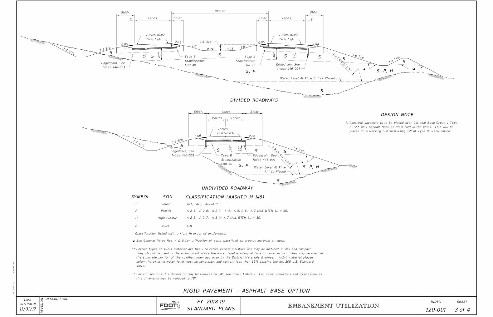
SYMBOL SOIL CLASSIFICATION (AASHTO M 145)
UNDIVIDED ROADWAY
DIVIDED ROADWAYS
DESIGN NOTE
S, P, H
S
S, P
S SS
S
SS S
S, P
S S
S
S
S, P, H
S
Shldr.
Lanes1'
Shldr.
Median
Shldr. Lanes1'
Shldr.
0.06 0.05
1:60.04 0.04
1:6
0.050.06
12"
48"*
48"*
12"
0.06 0.06
12"
48"*
S Select
P Plastic
H High Plastic
M Muck A-8
A-2-5, A-2-7, A-5 Or A-7 (ALL WITH LL > 50)
A-2-5, A-2-6, A-2-7, A-4, A-5, A-6, A-7 (ALL WITH LL < 50)
A-1, A-3, A-2-4 **
Classification listed left to right in order of preference.
this dimension may be reduced to 18".
For cut sections this dimension may be reduced to 24"; see Index 120-002. For minor collectors and local facilities *
sieve.
below the existing water level must be nonplastic and contain less than 15% passing the No. 200 U.S. Standard
the subgrade portion of the roadbed when approved by the District Materials Engineer. A-2-4 material placed
They should be used in the embankment above the water level existing at time of construction. They may be used in
Certain types of A-2-4 material are likely to retain excess moisture and may be difficult to dry and compact.**
See General Notes Nos. 4 & 5 for utilization of soils classified as organic material or muck.�
RIGID PAVEMENT - ASPHALT BASE OPTION
1:4 Std.1:6 St
d.
1:2 C
ontrol Lin
e
1:6 Typ.
1:4
Std.
1:4 Std.1:6 St
d.
1:6 Typ.
1:2 C
ontrol Lin
e
Shldr. Lanes Shldr.
VariesVaries
placed on a working platform using 12" of Type B Stabilization.
B-12.5 only Asphalt Base as identified in the plans. This will be
Concrete pavement is to be placed over Optional Base Group 1 Type 1.

10/23/2017
10:2
4:1
1
AM
RE
VISIO
N DESCRIPTION:
REVISION
LAST
ofSTANDARD PLANS
FY 2018-19 SHEETINDEX
11/01/17EMBANKMENT UTILIZATION
120-001 4 4
0.03 Typ.)
Varies (0.02-
0.03 Typ.)
Varies (0.02-
Water Level At Time Fill Is Placed
� �
� �2.5' Std.
See Index 446-001
Draincrete Edgedrain
�
�
(0.02-0.03)
Varies
Fill Is Placed
Water Level At Time
See Index 446-001
Draincrete Edgedrain
See Index 446-001
Draincrete Edgedrain
See Index 446-001
Draincrete Edgedrain
DIVIDED ROADWAYS
UNDIVIDED ROADWAY
S, P, H
S
S, P
S+S+S+S+
S
S, P, H
S S+ S+S+
S+S+S+S+
SYMBOL SOIL CLASSIFICATION (AASHTO M 145)
RIGID PAVEMENT - SPECIAL SELECT SOIL OPTION
Median
Shldr. Lanes Shldr. Shldr. Lanes Shldr.
Shldr.Lanes Shldr.
Varies Varies
0.06 0.06
0.06
0.05
1:60.04 0.04
1:6
0.05
0.06
1:2 C
ontrol Lin
e
1:2 C
ontrol Lin
e
60"
60"
60"
1:4 Std. 1:6 St
d.
S, P
1:4
Std.
1:6 Typ.
1:6 Typ.
1:6 St
d.1:4 Std.
S
S+
P
H
M Muck
High Plastic
Plastic
Special Select
Select
A-2-5, A-2-6, A-2-7, A-4, A-5, A-6, A-7 (ALL WITH LL<50)
A-2-5, A-2-7, A-5 Or A-7 (ALL WITH LL>50)
A-8
A-1, A-3, A-2-4 **
Classification listed left to right in order of preference.
3" of #57 or #89 Coarse Aggregate Mixed Into Top 6". �
below the existing water level must be nonplastic and contain less than 15% passing the No. 200 U.S. Standard sieve.
They should be used in the embankment above the water level existing at time of construction. A-2-4 material placed
Certain types of A-2-4 material are likely to retain excess moisture and may be difficult to dry and compact. **
U.S. Standard sieve.
This material must meet the minimum lab permeability requirement, be nonplastic, and not exceed 12% passing the No. 200
When allowed by the plans, some types of A-2-4 material may be approved in writing by the District Materials Engineer. ***
See General Notes Nos. 4 & 5 for utilization of soils classified as organic material or muck. �
writing by the District Materials Engineer and shown in the plans.
SPECIAL SELECT SOIL OPTION may be used only when approved in Note:
A-3 *** With Minimum Average Lab Permeability of 5x10�⁵ cm/sec. (0.14 ft./day) as per AASHTO T 215

Whether Or Not Shoulder Gutter Is Used
Control Line Set By Normal Shoulder Point
Limit For Minimum RemovalBottom Of Organic Material
*
Whether Or Not Shoulder Gutter Is Used
Control Line Set By Normal Shoulder Point
Limit For Minimum RemovalBottom Of Organic Material
*
*
Bottom Of Organic Material
Gutter Line
Back Of Proposed Or Future Sidewalk
Limit For Minimum Removal
*
Bottom Of Organic Material
Gutter Line
Back Of Proposed Or Future Sidewalk
Limit For Minimum Removal
10/23/2017
10:2
4:1
1
AM
RE
VISIO
N DESCRIPTION:
REVISION
LAST
ofSTANDARD PLANS
FY 2018-19 SHEETINDEX
11/01/17 120-002 1 2SUBSOIL EXCAVATION
WITH OVERBURDEN - HALF SECTION
WITH OVERBURDEN - HALF SECTION
GENERAL NOTES:
Outer Roadway
Organic Material
Overlying Material1:2 Control Line
Outer Roadway
1:2 Control LineOverlying Material
Organic Material
Outer Roadway
Organic Material
1:2 Control Line
WITHOUT OVERBURDEN - HALF SECTION
Outer Roadway
1:2 Control Line
Organic Material
WITHOUT OVERBURDEN - HALF SECTION
CONSTRUCTION OF FLUSH SHOULDER ROADWAY
CONSTRUCTION OF CURBED ROADWAY
GENERAL NOTES AND REMOVAL OF ORGANIC MATERIAL
Standard Specifications. The minimum grade of underdrain pipe is 0.02.
material will not extend above the bottom of the stabilized section of the subgrade. Gradation of the filter material must conform to
7. In areas of curbed roadway, where underdrain is to be constructed beneath the proposed pavement, the grade of the underdrain filter
on the portion of a sample passing the No. 4 sieve.
test results from a minimum of three randomly selected samples from each stratum. Perform tests in accordance with AASHTO T267
Index and the plans unless directed otherwise by the District Geotechnical Engineer. Determine the average organic content from the
percent, or an individual organic content test result which exceeds seven (7.0) percent. Remove organic material as shown on this
6. The term "Organic Material" as used on this Index is defined as any soil which has an average organic content greater than five (5.0)
*
accommodate one future median lane on each roadway unless specified otherwise by the plans.
the organic material removal limits will be set by a 1:2 control line complimentary to the outer roadway that will
to divided facilities with median widths up to 64'; When median width is greater than 64' and for bifurcated roadways
unless approved otherwise by the District Geotechnical Engineer; The limits include full median width when applied
Remove overlying material and organic material within the limits shown and backfill in accordance with Index 120-001,
5. See Index 000-506 for miscellaneous earthwork details.
classifications for Plastic (P) and High Plastic (H) on Index 120-001.
4. The term "Plastic Material" used in this Index in conjunction with removal of plastic soil is as defined under soil
unless otherwise shown on the plans.
3. Where organic or plastic material is undercut, backfill with suitable material in accordance with Index 120-001,
2. Utilize excavated materials in accordance with Index 120-001.
1. All details shown on this Index for removal of organic and plastic materials apply unless otherwise shown on the plans.
6"6"
24"
24"
24"
24"
Remove Plastic Material To This Line
24"
24" 2
4"
24"
Remove Plastic Material To This Line
6"
Remove Plastic Material To This Line
24"
24"
24"
Remove Plastic Material To This Line
24" 2
4"
12"
6"
24"
1:2 Control Line
This line (See Note #3)Remove Plastic Material To
Gutter Line
1'-6"
12" 12"
6"
24"
Gutter Line
1'-6"
(See Note #5)Outer Cut Limit
At Outer Control Line LimitWhen Underdrain LocatedExtended Undercut Slope
12"
6"
1:2 Control Line
1'-6"
At Back Of CurbWhen Underdrain Located0.02 Undercut Backslope
(See Note #5)Inner Cut Limit
Underdrain
To This line (See Note #3)Remove Plastic Material
Of Plastic MaterialMinimum Removal Cut Limit For
SPECIAL REMOVAL DETAIL
(See GENERAL NOTE #7)Underdrain (See Index 440-001)
(See GENERAL NOTE #7)Underdrain (See Index 440-001)
10/23/2017
10:2
4:1
2
AM
RE
VISIO
N DESCRIPTION:
REVISION
LAST
ofSTANDARD PLANS
FY 2018-19 SHEETINDEX
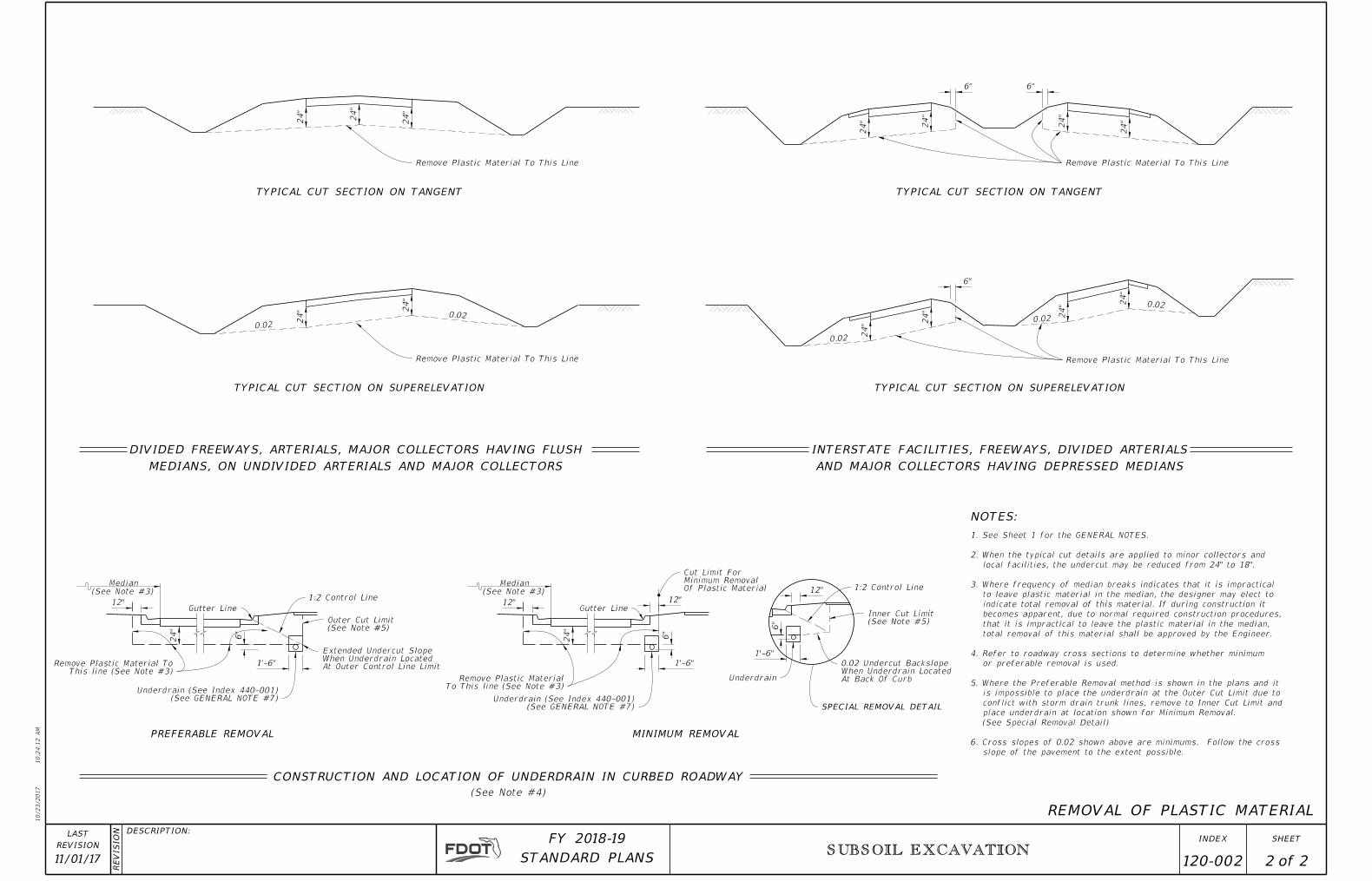
11/01/17 120-002 2 2SUBSOIL EXCAVATION
REMOVAL OF PLASTIC MATERIAL
NOTES:
AND MAJOR COLLECTORS HAVING DEPRESSED MEDIANS
INTERSTATE FACILITIES, FREEWAYS, DIVIDED ARTERIALS
TYPICAL CUT SECTION ON TANGENT
0.02
MEDIANS, ON UNDIVIDED ARTERIALS AND MAJOR COLLECTORS
DIVIDED FREEWAYS, ARTERIALS, MAJOR COLLECTORS HAVING FLUSH
TYPICAL CUT SECTION ON SUPERELEVATION
TYPICAL CUT SECTION ON TANGENT
0.02
0.02
0.02
0.02
TYPICAL CUT SECTION ON SUPERELEVATION
slope of the pavement to the extent possible.
6. Cross slopes of 0.02 shown above are minimums. Follow the cross
(See Special Removal Detail)
place underdrain at location shown for Minimum Removal.
conflict with storm drain trunk lines, remove to Inner Cut Limit and
is impossible to place the underdrain at the Outer Cut Limit due to
5. Where the Preferable Removal method is shown in the plans and it
or preferable removal is used.
4. Refer to roadway cross sections to determine whether minimum
total removal of this material shall be approved by the Engineer.
that it is impractical to leave the plastic material in the median,
becomes apparent, due to normal required construction procedures,
indicate total removal of this material. If during construction it
to leave plastic material in the median, the designer may elect to
3. Where frequency of median breaks indicates that it is impractical
local facilities, the undercut may be reduced from 24" to 18".
2. When the typical cut details are applied to minor collectors and
1. See Sheet 1 for the GENERAL NOTES.
Median
(See Note #3)
Median
(See Note #3)
CONSTRUCTION AND LOCATION OF UNDERDRAIN IN CURBED ROADWAY
MINIMUM REMOVAL
(See Note #4)
PREFERABLE REMOVAL

10/23/2017
10:2
4:1
3
AM
RE
VISIO
N DESCRIPTION:
REVISION
LAST
ofSTANDARD PLANS
FY 2018-19 SHEETINDEX
1'-6"
Varies
Ditch Width (w)
1'-0" 1'-0"
Ditch Width (w) + 4'-0"
(See Notes Below)
Stage #2 Backfill
(See Notes Below)
Stage #1 Backfill
Utility Accommodaton Manual
See Location Criteria In the
1'-0"
4"
1'-0"Varies1'-0"
Utility Accommodaton Manual
See Location Criteria In the
10"Nearest Joint In Pavement Nearest Joint In Pavement
10'-0" (Min.) 10'-0" (Min.)
(Min.) 2'-0"
(Min.) 2'-0"
10'-0" (Min.) Monolithic Slab
Stage #2 Backfill (See Notes Below)
Stage #1 Backfill (See Notes Below)
= Replacement Pavement
= Replacement Base = Replacement Pavement
(Not Less Than 8" Thickness)
Match The Existing Pavement Thickness
Flowable Fill Option Is Used
#9 Stone Or Equivalent When
Butt Construction Joint
Refer To Index 350-001 For
11/01/17 125-001 1 2UTILITY ADJUSTMENTS THRU EXISTING PAVEMENT
Course & Friction Course
Replacement Structural
FLEXIBLE PAVEMENT CUT
TRENCH CUTS AND RESTORATIONS ACROSS ROADWAYS
GENERAL NOTES
NOTES:
9. Excavatable flowable fill is to be used when the flowable fill option is selected.
engineering document shall address the evaluation of local groundwater flow interruption and settlement potential.
supported by an engineering document prepared by a registered professional engineer that specializes in soils engineering. The
installed for significant depths or lengths. The maximum length shall be fifty (50) feet and a maximum depth of six (6) feet unless
Flowable fill use is allowed only when properly engineered for pavement crossings, whether straight or diagonal, and shall not be
8. The use of flowable fill to reduce the time traffic is taken off a facility is acceptable but must have prior approval by the Engineer.
7. All shoulder pavement, curb, curb and gutter, and their substructure disturbed by utility trench cut construction shall be restored in kind.
match the existing friction course, except structural course may be used in lieu of dense graded friction course.
over the replacement slab. The overlay shall match the existing asphalt pavement thickness. The replacement friction course shall
6. Where asphalt concrete overlays exist over full slab concrete pavement, the replacement pavement shall have an overlay constructed
NOTES:
RIGID PAVEMENT CUT
granular material.
5. Some pipe may require special granular backfill up to 6" above top of pipe. Geotextiles may be required to encapsulate the special
4. Method of construction must be approved by the Engineer.
geotextiles, special bedding and backfill, or other special requirements.
3. These details do not apply to utility cuts longitudinal to the centerline of the roadway which may require the additional use of
prevent pavement settlement.
due to fill weight. Where highly compressible material exists, the amount, shape and depth of flowable fill must be engineered to
2. Flowable fill shall not be placed directly over loose, or high plastic, or muck material (see Index 120-001) which will cause settlement
by the Engineer.
1. The details provided in this Index apply to cases in which jack and bore or directional boring methods are not required
E. In Stage #2, place flowable fill to the bottom of the stone layer.
D. In Stage #1, place flowable fill midway up on both sides of the utility. Allow to harden before placing Stage #2.
Stages #1 and #2 can be combined, if approved by the Engineer.
C. Do not allow the utility being installed to float. If a method is provided to prevent flotation from occurring,
B. Flowable fill is to be placed in accordance with Section 121 of the Specifications, as approved by the Engineer.
A. If mechanical compaction can not be achieved through normal mechanical methods then flowable fill may be used.
2. FLOWABLE FILL
D. In Stage #2, construct fill along the sides of the pipe and up to the bottom of replacement pavement.
any bedding.
this purpose. This compaction applies to the material placed beneath the haunches of the pipe and above
C. In Stage #1, construct compacted fill beneath the haunches of the pipe, using mechanical tamps suitable for
select soil in accordance with Index 350-001.
B. Fill material shall be placed in accordance with the Standard Specifications. Fill material shall be special
that is damaged shall be repaired with methods approved by the Engineer.
A. Any edgedrain system that is removed shall be replaced with the same type materials. Any edgedrain system
1. GRANULAR BACKRILL
BACKFILL OPTION
(See Index 350-001)
2. Pavement shall be mechanically sawed and restored to conform with existing pavement joints within 12 hours.
be used for rigid pavement replacement.
1. High early strength cement concrete (3000 psi) meeting the requirements of Standard Specification 346 shall
PAVEMENT REMOVAL AND REPLACEMENT
E. In Stage #2, place flowable fill to the bottom of the existing base course.
Stage #2.
D. In Stage #1, place flowable fill midway up on both sides of the utility. Allow to harden before placing
occurring, Stages #1 and #2 can be combined, if approved by the Engineer.
C. Do not allow the utility being installed to float. If a method is provided to prevent flotation from
the Engineer.
B. Flowable fill is to be placed in accordance with Section 121 of the Specifications, as approved by
A. If compaction can not be achieved through normal mechanical methods then flowable fill may be used.
2. FLOWABLE FILL
using Optional Base Group 3.
the upper 12" receiving Type B Stabilization. In lieu of Type B Stabilization, the Contractor may construct
C. In Stage #2, construct compacted fill along the sides of the pipe and up to the bottom of the base, with
above any bedding.
for this purpose. This compaction applies to the material placed beneath the haunches of the pipe and
B. In Stage #1, construct compacted fill beneath the haunches of the pipe, using mechanical tamps suitable
A. Place backfill material in accordance with Specifications 125.
1. COMPACTED AND STABILIZED FILL
BACKFILL OPTION
equal or greater structural adequacy.
3. The new base materials shall be either of the same type and composition as the materials removed or of
accordance with current FDOT asphalt mix specifications.
2. The replacement asphalt shall match the existing structural and friction courses for type and thickness in
1. Pavement shall be mechanically sawed.
PAVEMENT REMOVAL AND REPLACEMENT
Longitudinal Cut-Line
Longitudinal Cut-Line
Transverse Cut-Line
Transverse Cut-Line
1'-0" (Min.)
1'-
0" (Min.)
1'-0" (Min.)
1'-
0" (Min.)
10/23/2017
10:2
4:1
3
AM
RE
VISIO
N DESCRIPTION:
REVISION
LAST
ofSTANDARD PLANS
FY 2018-19 SHEETINDEX
11/01/17 125-001 2 2UTILITY ADJUSTMENTS THRU EXISTING PAVEMENT
NOTES
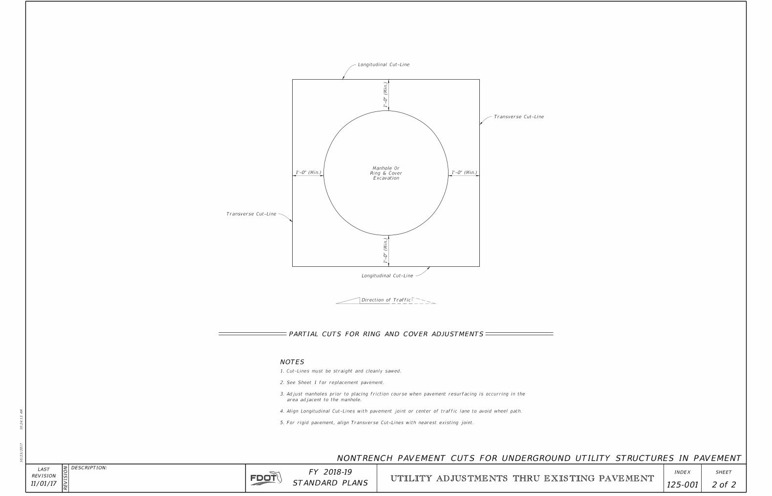
PARTIAL CUTS FOR RING AND COVER ADJUSTMENTS
NONTRENCH PAVEMENT CUTS FOR UNDERGROUND UTILITY STRUCTURES IN PAVEMENT
Excavation
Ring & Cover
Manhole Or
Direction of Traffic
5. For rigid pavement, align Transverse Cut-Lines with nearest existing joint.
4. Align Longitudinal Cut-Lines with pavement joint or center of traffic lane to avoid wheel path.
area adjacent to the manhole.
3. Adjust manholes prior to placing friction course when pavement resurfacing is occurring in the
2. See Sheet 1 for replacement pavement.
1. Cut-Lines must be straight and cleanly sawed.

10/6/2017
12:4
9:4
0 P
M
RE
VISIO
N DESCRIPTION:
REVISION
LAST
ofSTANDARD PLANS
FY 2018-19 SHEETINDEX
SETTLEMENT PLATE
01/01/00 1 1 141-T016"
6-2"x8" Treated Timbers
2"x6" Treated Timber
212" Steel or PVC Schedule 40 Pipe (Casing).
Casing to be installed in 5' sections, as required.
Threaded or Socket Type Fittings (PVC Socket Type shown)
PVC casing sections not permitted below steel sections
Coupling (As Required)
Cement when Socket Type Coupling used
Iron Coupling (As Required)
1" Iron Pipe (Marker)
Lower pipe section to be 4'-6" in length
Added pipe sections to be 5'-0" in length
Stem To Be Plumb
Top Of Lift Or
Top Of Full Surcharge2' Min.
Fill Within 3' Of Stem
Shall Be Compacted By
Hand To Required Density
Plate To Be Seated (Level) After Clearing
And Grubbing & Demucking Operations And
Prior To Placing First Fill Lift
Surcharge
(Compacted Fill )
Top Of Strata To Be Surcharged
NOTES:
Oakum Seal
Iron Pipe unthreaded this end
316
316
Iron Pipe Cap
Oakum Seal
6"
Oakum Seal
Iron Pipe Cap
Iron Pipe Cap
Oakum Seal
2"x6" Treated Timber
(See Detail Above)
Timber Plate
6"
6"
58" Dia. Hole
58" Dia. Hole
TIMBER PLATE STEEL PLATE
STEM AND PLATE OPTIONS
STEEL PLATE STEEL PLATE
INSTALLATION
4'
PLAN
TIMBER PLATE
¢ 12 x 24¢ 12 x 24¢ 12 x 24
1. Elevation of the top of each length of marker
pipe shall be determined as soon as it is installed
and also immediately before the next length of
marker pipe is added.
2. Settlement plate locations shall be flagged and
protected from construction vehicles and equipment.
If settlement plates are disturbed, they shall be
replaced in kind.
3. Oakum used to construct seal should not have a
mesh covering (plastic or other synthetic material).
4. The settlement plates shall be paid for under
the contract unit price for Settlement Plate
Assembly, AS.
Threaded or Socket Type Cap.
Stamp or label with Installation Date, Location and Identification Number
(when Socket Type Cap is used drill 14" diameter holes and secure with wire.
Threaded Type Caps to be hand tightened.)
12" Dia. x 11
2" Hex Head
Bolt, Nut & Washer. Deform
thread or use Jam Nut
12" Dia. Hex Head Bolt,
Nut & Washer. Deform
thread or use Jam Nut
12" Dia. Bolt, Nut & Washer
(Bolt thread end up)