Possible Involvment of TSO in SCWR Project
23
Centrum výzkumu Řež s.r.o. Possible Involvment of TSO in SCWR Project Guido Mazzini 22.1.2013
Transcript of Possible Involvment of TSO in SCWR Project
Centrum výzkumu Řež s.r.o.
Possible Involvment of TSO in SCWR
Project
Guido Mazzini22.1.2013

Outlook
IntroductionDescription of SCWR -FQT FacilitySummary of the Most Relevant Safety Aspects
Design LimitsDescription of DBAsDescription of Safety AssessmentConsequences of Pressure Tube Rupture (SA)
Open Questions in the Design of the Facility SCWR -FQT
Questions and Suggestions for the AnalysesPossible Collaboration with TSO?
1

Introduction
Aim of this presentation is:
• To focus on the main safety aspects evidenced in the documents SCWR -FQT deliverables E1.1, E2.1, E3.1 and in the Annex 1.
• To evidence open questions in the project from the safety point of view.
• To give suggestions/observations useful for the designers.
• To propose a possible collaboration with TSO group and the teams/partners of SCWR -FQT on the framework of SUSEN project.
2

Description of Facility SCWR -FQT
3

Description of Facility SCWR -FQT
4
Active Channel:

Description of Facility SCWR -FQT
Parameters of Active Channel:
Nominal working pressure 25 MPa
Max. working pressure 32 MPa
Max. cladding temperature of fuel rods during normal operation 700 °C
Max. fuel power 70 kW/m
Max. working temperature of pressure tube 400 °C
Nominal flow rate in the active channel AK 900 kg/h
Nominal thermal power of 4 fuel rods 55 kW
Coolant velocity around the fuel rods 3÷4 m/s
5

Description of Facility SCWR -FQT
6

Description of Facility SCWR -FQT
7
Active Channel Description:

Description of Facility SCWR -FQT
8
Safety Systems:
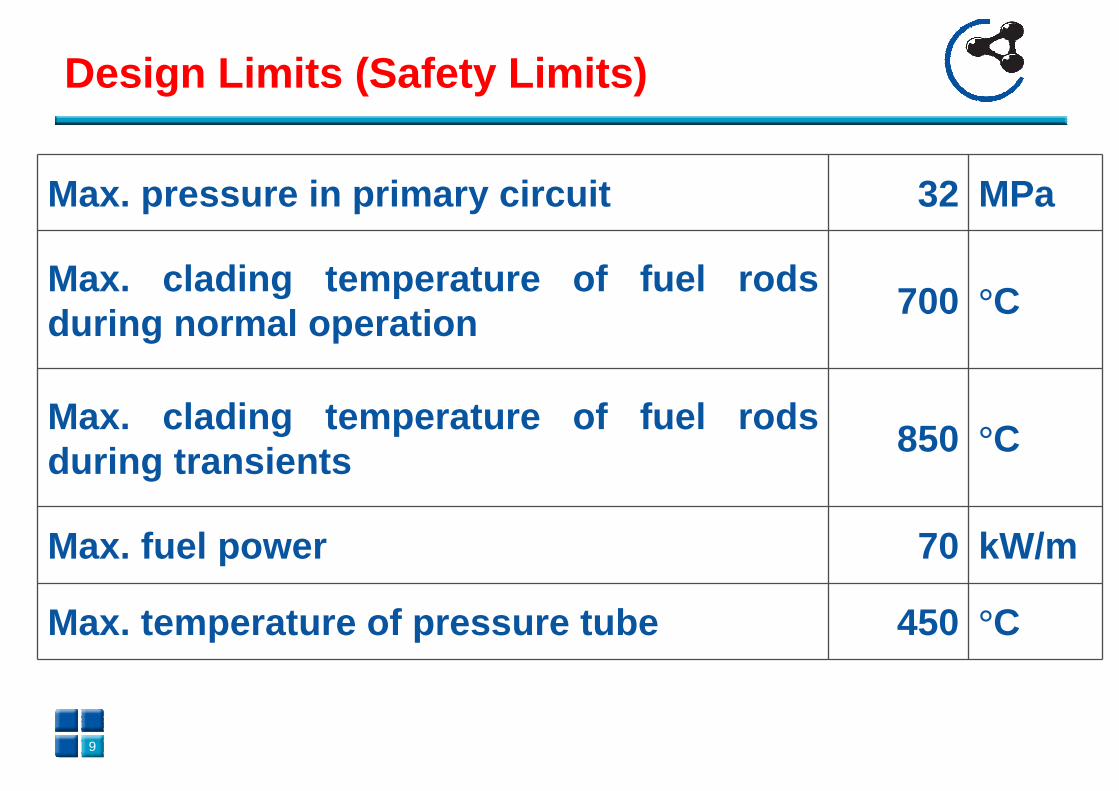
Design Limits (Safety Limits)
Max. pressure in primary circuit 32 MPa
Max. clading temperature of fuel rods during normal operation
700 °C
Max. clading temperature of fuel rods during transients
850 °C
Max. fuel power 70 kW/m
Max. temperature of pressure tube 450 °C
9

ATLETH Input sketch
10
Active Channel:

ATLETH Input sketch
11
Safety Systems:

Description of DBAs
Loss of coolant due to break of any coolant supply line . The countermeasures may include scram of the reactorand low pressure coolant injection after depressurization .
Trip of the primary pump . The countermeasures may include scram of the reactor, active depressurisation and low pressure coolant injection .
Loss of electricity supply for the loop. The countermeasures may be scram of the reactor , passive depressurisation and low pressure coolant injection with a battery driven pump.
12

Blockage of the coolant flow path . The countermeasures may be scram of the reactor , active depressurisationand direct coolant injection into the test section with an emergency coolant system.
Detachment of the wire wrap or other spacer conceptdesigned for the fuel assembly, causing local block age inside the test section. Even in these cases, a depressurization with direct emergency coolant injection shall cool the test section properly.
Fatigue of the internal structures of the pressure tube by coolant temperature differences and associated thermal stresses .
Description of DBAs
13
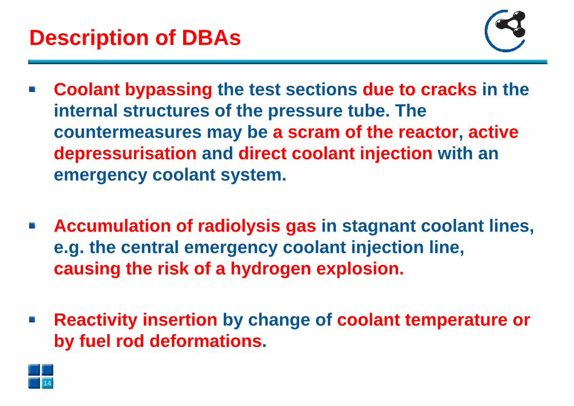
Coolant bypassing the test sections due to cracks in the internal structures of the pressure tube. The countermeasures may be a scram of the reactor , active depressurisation and direct coolant injection with an emergency coolant system.
Accumulation of radiolysis gas in stagnant coolant lines, e.g. the central emergency coolant injection line, causing the risk of a hydrogen explosion.
Reactivity insertion by change of coolant temperature or by fuel rod deformations .
Description of DBAs
14

Description of Safety Assessment
Thermal fatigue of the pressure tube by local thermal stresses due to coolant temperature differences.Creep rupture of the pressure tube due to a un-cooled test section . Spontaneous rupture of the pressure tube due to a sudden, violent steam generation ,
Caused by a reactivity excursion of the core and thus a power excursion of the test fuel rods;Caused by re-wetting of overheated test fuel rods.
Failure of the pressure tube due to hydrogen formation at superheated fuel rods, followed by a hydrogen deflagration .
15

“ A rupture or explosion of the pressure tube inside the reactor could damage the reactor core or the control rods and thus cause a severe secondary damage .”
“Even if the probability of such an accident will be extremely low , it is the intent of this task to identify all imaginable secondary damages such that counter-measures can be provided to limit any secondary damages to the reactor confinement .”
16
Consequences of Pressure Tube Rupture
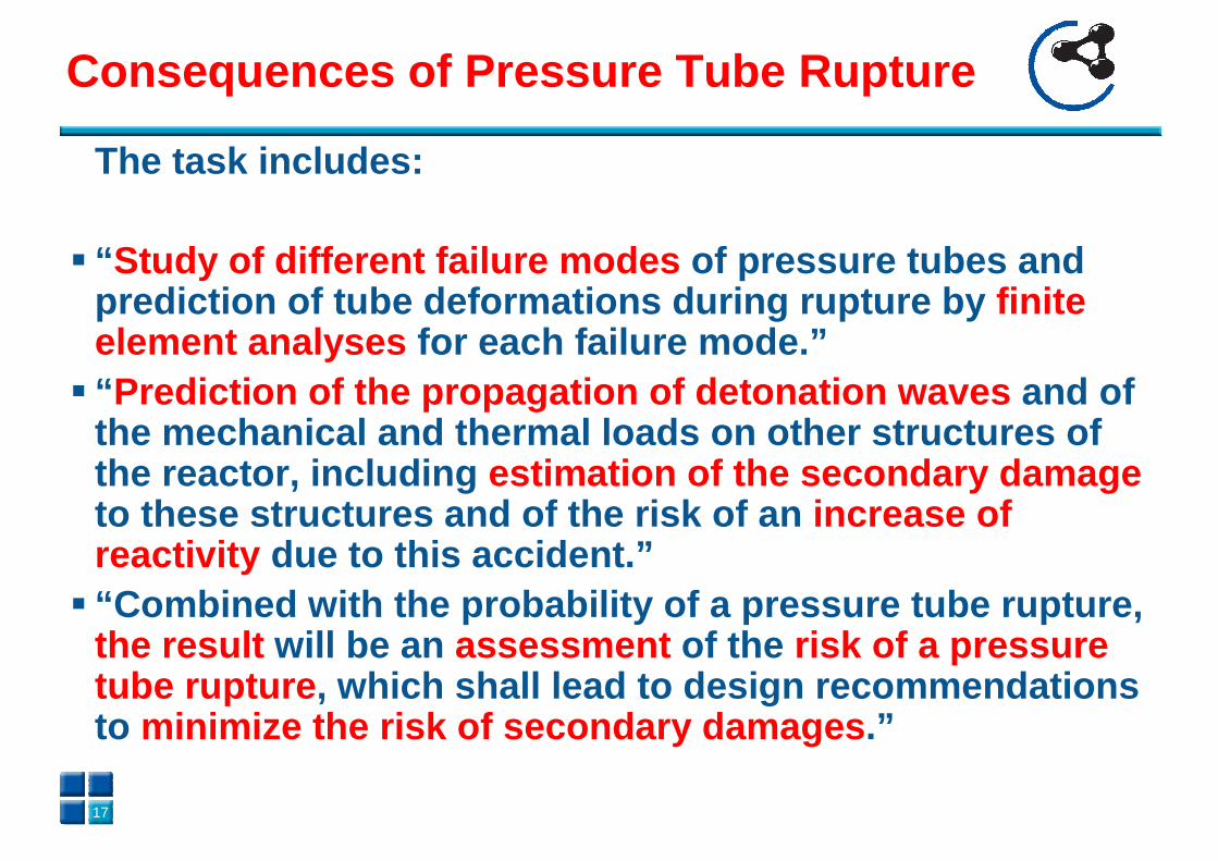
The task includes:
� “ Study of different failure modes of pressure tubes and prediction of tube deformations during rupture by finite element analyses for each failure mode.”
� “ Prediction of the propagation of detonation waves and of the mechanical and thermal loads on other structure s of the reactor, including estimation of the secondary damageto these structures and of the risk of an increase of reactivity due to this accident.”
� “Combined with the probability of a pressure tube r upture, the result will be an assessment of the risk of a pressure tube rupture , which shall lead to design recommendations to minimize the risk of secondary damages .”
17
Consequences of Pressure Tube Rupture
Open Questions in the Design of the Facility SCWR -FQT
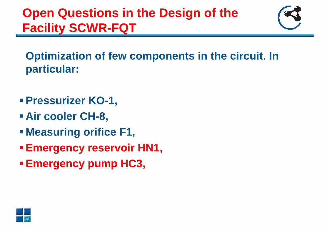
Optimization of few components in the circuit. In particular:
�Pressurizer KO -1,�Air cooler CH -8,�Measuring orifice F1,�Emergency reservoir HN1, �Emergency pump HC3,
18
Open Questions in the Design of the Facility SCWR -FQT
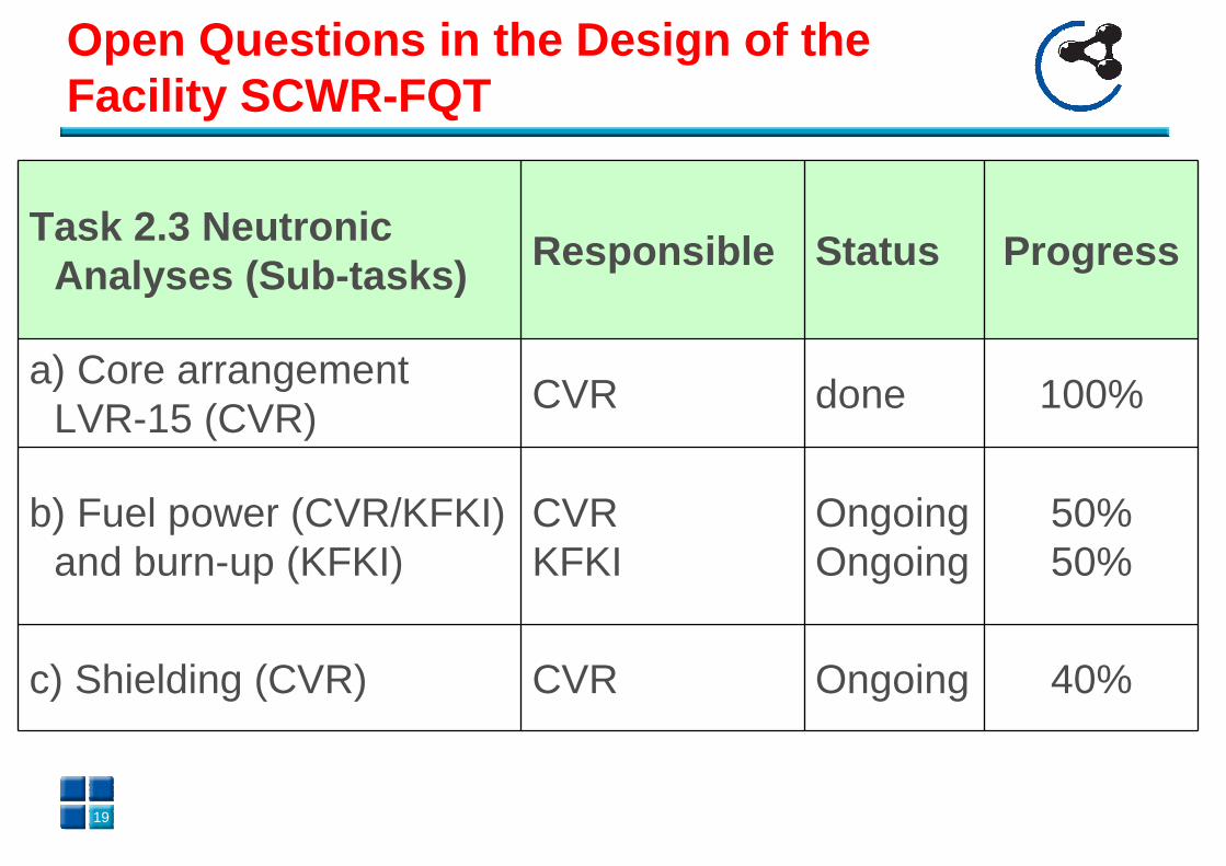
Task 2.3 NeutronicAnalyses (Sub -tasks)
Responsible Status Progress
a) Core arrangement LVR-15 (CVR)
CVR done 100%
b) Fuel power (CVR/KFKI) and burn-up (KFKI)
CVRKFKI
OngoingOngoing
50%50%
c) Shielding (CVR) CVR Ongoing 40%
19

Questions on the Analyses
1. Is Reactivity under control in any possible scenario?
2. What happens in case of an explosion of Active Channel ? Is there any damage for LVR -15?
3. Which is the mass inventory of the Active Channel?
4. Is it possible to assure the integrity of the confinement in any condition ?
20

Suggestions for the Analyses
1. No SA accident with spread of material out the core of LVR-15
2. Calculate reactivity changes under accident3. Estimate the mass inventory of FQT facility in order to
have an idea of the FP release4. Evaluate scenarios with a code able to evaluate source
term5. Demonstrate , if the fuel melts and releases FP outside
the channel, that no significant consequences occur for the environment and people . If not, add systems to contain and confine the Source Term (filters, evaluation of the peak pressure for hydrogen combustion/explosion, check of the penetrations)
21

Possible Collaboration with TSO
Perform analyses on the basis of the reference data with RELAP or TRACE as independent review of the work done with ATLHET?
Prepare analyses with MELCOR or ASTEC to evaluate the behaviour of the active channel if it enters in a melting scenario?
Help for other calculations (neutronics and burn -up) or support to experimental work ?
22