
Possibilities to Use Multi-Body System Simulation Results ... … · Possibilities to Use...
28
Fakultät Maschinenwesen, Institut für Maschinenelemente und Maschinenkonstruktion, Lehrstuhl Maschinenelemente Possibilities to Use Multi-Body System Simulation Results to Design Components of Large Drivetrains SIMPACK User Meeting 2014 Prof. Dr.-Ing. Berthold Schlecht | Dr.-Ing. Thomas Rosenlöcher Augsburg, 9. October 2014
Transcript of Possibilities to Use Multi-Body System Simulation Results ... … · Possibilities to Use...

Fakultät Maschinenwesen, Institut für Maschinenelemente und Maschinenkonstruktion, Lehrstuhl Maschinenelemente
Possibilities to Use Multi-Body System Simulation Results to Design Components of Large Drivetrains
SIMPACK User Meeting 2014
Prof. Dr.-Ing. Berthold Schlecht | Dr.-Ing. Thomas Rosenlöcher
Augsburg, 9. October 2014

Prof. Dr.-Ing. Berthold Schlecht | Dr.-Ing. Thomas Rosenlöcher
Technische Universität DresdenChair of Machine Elements
• Technische Universität Dresden Chair of Machine Elements
• Field of research: drive technology, especially gear technology and components
09.10.2014 2Possibilities to Use Multi-Body System Simulation Results to Design Components of Large Drivetrains
Prof. Dr.-Ing. Berthold Schlecht | Dr.-Ing. Thomas Rosenlöcher
Technische Universität DresdenChair of Machine Elements
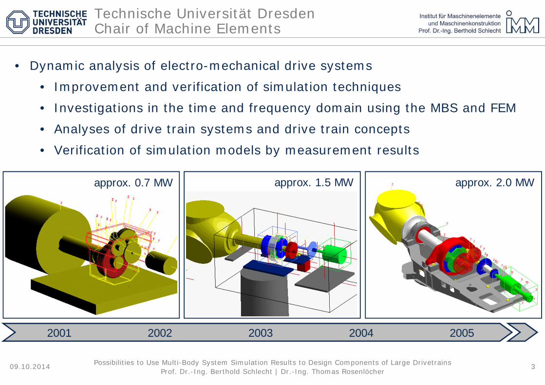
• Dynamic analysis of electro-mechanical drive systems• Improvement and verification of simulation techniques• Investigations in the time and frequency domain using the MBS and FEM• Analyses of drive train systems and drive train concepts• Verification of simulation models by measurement results
09.10.2014 3Possibilities to Use Multi-Body System Simulation Results to Design Components of Large Drivetrains
2001 2002 2003 2004 2005
approx. 0.7 MW approx. 1.5 MW approx. 2.0 MW

Prof. Dr.-Ing. Berthold Schlecht | Dr.-Ing. Thomas Rosenlöcher09.10.2014 4Possibilities to Use Multi-Body System Simulation Results to Design Components of Large Drivetrains
Dynamic analysis of electro-mechanical drive systems
roller mill train drive ladle cranes
thruster bucket wheel excavatormechanical watches

Prof. Dr.-Ing. Berthold Schlecht | Dr.-Ing. Thomas Rosenlöcher
• Overhead crane with 4 welded box girder• Span width 22 m, service weight: 770 t
09.10.2014 5Possibilities to Use Multi-Body System Simulation Results to Design Components of Large Drivetrains
Analysis of a 400 t ladle crane drive train

Prof. Dr.-Ing. Berthold Schlecht | Dr.-Ing. Thomas Rosenlöcher09.10.2014 6Possibilities to Use Multi-Body System Simulation Results to Design Components of Large Drivetrains
Analysis of a 400 t ladle crane drive train
Parameter Determination
(mass, mass moment of inertia)
SSS
ZZYYXX
zyxm
III
,,
,,
Flexibility of shafts(discretisation, beam approaches,
finite-element models)
Bearings Couplings
source: www.tschan.de
Rope drum, traverse
Gearing(GEAR PAIR, user routines)
Gear boxes and supporting structure

Prof. Dr.-Ing. Berthold Schlecht | Dr.-Ing. Thomas Rosenlöcher
• Frequency domain, natural frequency at 0.4 Hz
09.10.2014 7Possibilities to Use Multi-Body System Simulation Results to Design Components of Large Drivetrains
Analysis of a 400 t ladle crane drive train

Prof. Dr.-Ing. Berthold Schlecht | Dr.-Ing. Thomas Rosenlöcher
• Frequency domain, natural frequency at 63.7 Hz
09.10.2014 8Possibilities to Use Multi-Body System Simulation Results to Design Components of Large Drivetrains
Analysis of a 400 t ladle crane drive train

Prof. Dr.-Ing. Berthold Schlecht | Dr.-Ing. Thomas Rosenlöcher
• Influence of the level of detail of the simulation model to the torsional natural frequencies
09.10.2014 9Possibilities to Use Multi-Body System Simulation Results to Design Components of Large Drivetrains
Analysis of a 400 t ladle crane drive train
variant
V6 V5 V4 V3 V2 V1
level of detail of the model
modelled as modal reduced
FE-model
supporting structure X
main gearbox X X
drum gearbox X X
gearbox, 6 degrees of freedom X X
degrees of freedom
of drivetrain compon-
ents
equatorial rotat. axes X X X
radial displacement X X X X
axial displacement X X X X X
polar axis of rotation X X X X X X
calculated natural frequencies
1st torsional natural frequency [Hz] 26.3 29.3 30.4 30.6 30.7 30.7
2nd torsional natural frequency [Hz] 31.1 30.5 33.5 38.0 48.3 48.5
3rd torsional natural frequency [Hz] 31.9 33.5 37.0 45.1 50.9 51.9
4th torsional natural frequency [Hz] 48.6 52.0 62.6 86.0 143.1 163.3

Prof. Dr.-Ing. Berthold Schlecht | Dr.-Ing. Thomas Rosenlöcher
• Load cases to be analysed
• Braking concept• Redundant system, consists of
operational brakes on the motor sided shafts and emergency stop brakes on the rope drums
09.10.2014 10Possibilities to Use Multi-Body System Simulation Results to Design Components of Large Drivetrains
Analysis of a 400 t ladle crane drive train
Reason for the emergency stop
Emergency stop
Breakage of a shaft
Direction of motion
Upwards Downwards
Load TraverseTraverse and filled ladle
Prof. Dr.-Ing. Berthold Schlecht | Dr.-Ing. Thomas Rosenlöcher09.10.2014 11Possibilities to Use Multi-Body System Simulation Results to Design Components of Large Drivetrains
Analysis of a 400 t ladle crane drive train
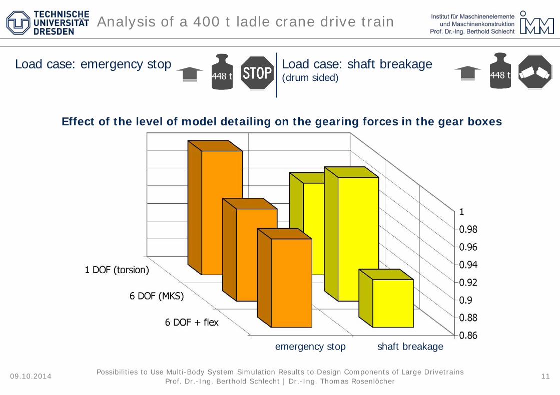
Load case: emergency stop Load case: shaft breakage(drum sided)
Effect of the level of model detailing on the gearing forces in the gear boxes
emergency stop shaft breakage

Prof. Dr.-Ing. Berthold Schlecht | Dr.-Ing. Thomas Rosenlöcher09.10.2014 12Possibilities to Use Multi-Body System Simulation Results to Design Components of Large Drivetrains
Analysis of a 400 t ladle crane drive train

Prof. Dr.-Ing. Berthold Schlecht | Dr.-Ing. Thomas Rosenlöcher
• 3-point supported drivetrain, rotor diameter 90 m, 3-staged planetary-helical gear stage gear box
09.10.2014 13Possibilities to Use Multi-Body System Simulation Results to Design Components of Large Drivetrains
Analysis of a 3 MW windturbine

Prof. Dr.-Ing. Berthold Schlecht | Dr.-Ing. Thomas Rosenlöcher
• Influence of the level of detail of the simulation model to the torsional natural frequencies
09.10.2014 14Possibilities to Use Multi-Body System Simulation Results to Design Components of Large Drivetrains
Analysis of a 3 MW windturbine
variant
V8 V7 V6 V5 V4 V3 V2 V1
level of detail of the model
modelled as modal
reduced finite-
element-model
main frame X
gearbox housing X
main shaft X X
planet carrier X X X
gearbox housing, 6 degrees of freedom X X X X
degrees of freedom of
the drivetrain components
equatorial rotation axes X X X X X
radial displacement X X X X X X
axial displacement X X X X X X X
polar axis of rotation X X X X X X X X
flexible rotor blades X X X X X X X X
calculated natural frequencies
1st torsional natural frequency [Hz] 1.5 1.5 1.7 1.7 2.2 2.2 2.2 2.2
2nd torsional natural frequency [Hz] 2.9 2.9 3.0 3.1 4.1 4.1 4.1 4.1
3rd torsional natural frequency [Hz] 6.2 6.2 6.3 6.3 8.0 8.0 8.1 8.1
4th torsional natural frequency [Hz] 13.2 13.2 13.3 13.3 16.2 16.2 16.5 16.5

Prof. Dr.-Ing. Berthold Schlecht | Dr.-Ing. Thomas Rosenlöcher
• Influence of the level of detail of the simulation model to the torsional natural frequencies
• Degrees of freedom of the gearbox housing
09.10.2014 15Possibilities to Use Multi-Body System Simulation Results to Design Components of Large Drivetrains
Analysis of a 3 MW windturbine
variant
V8 V7 V6 V5 V4 V3 V2 V1
level of detail of the model
modelled as modal
reduced finite-
element-model
main frame X
gearbox housing X
main shaft X X
planet carrier X X X
gearbox housing, 6 degrees of freedom X X X X
degrees of freedom of
the drivetrain components
equatorial rotation axes X X X X X
radial displacement X X X X X X
axial displacement X X X X X X X
polar axis of rotation X X X X X X X X
flexible rotor blades X X X X X X X X
calculated natural frequencies
1st torsional natural frequency [Hz] 1.5 1.5 1.7 1.7 2.2 2.2 2.2 2.2
2nd torsional natural frequency [Hz] 2.9 2.9 3.0 3.1 4.1 4.1 4.1 4.1
3rd torsional natural frequency [Hz] 6.2 6.2 6.3 6.3 8.0 8.0 8.1 8.1
4th torsional natural frequency [Hz] 13.2 13.2 13.3 13.3 16.2 16.2 16.5 16.5

Prof. Dr.-Ing. Berthold Schlecht | Dr.-Ing. Thomas Rosenlöcher
• Influence of the level of detail of the simulation model to the torsional natural frequencies
• Elasticity of the main shaft
09.10.2014 16Possibilities to Use Multi-Body System Simulation Results to Design Components of Large Drivetrains
Analysis of a 3 MW windturbine
variant
V8 V7 V6 V5 V4 V3 V2 V1
level of detail of the model
modelled as modal
reduced finite-
element-model
main frame X
gearbox housing X
main shaft X X
planet carrier X X X
gearbox housing, 6 degrees of freedom X X X X
degrees of freedom of
the drivetrain components
equatorial rotation axes X X X X X
radial displacement X X X X X X
axial displacement X X X X X X X
polar axis of rotation X X X X X X X X
flexible rotor blades X X X X X X X X
calculated natural frequencies
1st torsional natural frequency [Hz] 1.5 1.5 1.7 1.7 2.2 2.2 2.2 2.2
2nd torsional natural frequency [Hz] 2.9 2.9 3.0 3.1 4.1 4.1 4.1 4.1
3rd torsional natural frequency [Hz] 6.2 6.2 6.3 6.3 8.0 8.0 8.1 8.1
4th torsional natural frequency [Hz] 13.2 13.2 13.3 13.3 16.2 16.2 16.5 16.5

Prof. Dr.-Ing. Berthold Schlecht | Dr.-Ing. Thomas Rosenlöcher
• Influence of the level of detail of the simulation model to the torsional natural frequencies
• Elasticity of the planet carrier and the supportingstructure
09.10.2014 17Possibilities to Use Multi-Body System Simulation Results to Design Components of Large Drivetrains
Analysis of a 3 MW windturbine
variant
V8 V7 V6 V5 V4 V3 V2 V1
level of detail of the model
modelled as modal
reduced finite-
element-model
main frame X
gearbox housing X
main shaft X X
planet carrier X X X
gearbox housing, 6 degrees of freedom X X X X
degrees of freedom of
the drivetrain components
equatorial rotation axes X X X X X
radial displacement X X X X X X
axial displacement X X X X X X X
polar axis of rotation X X X X X X X X
flexible rotor blades X X X X X X X X
calculated natural frequencies
1st torsional natural frequency [Hz] 1.5 1.5 1.7 1.7 2.2 2.2 2.2 2.2
2nd torsional natural frequency [Hz] 2.9 2.9 3.0 3.1 4.1 4.1 4.1 4.1
3rd torsional natural frequency [Hz] 6.2 6.2 6.3 6.3 8.0 8.0 8.1 8.1
4th torsional natural frequency [Hz] 13.2 13.2 13.3 13.3 16.2 16.2 16.5 16.5

Prof. Dr.-Ing. Berthold Schlecht | Dr.-Ing. Thomas Rosenlöcher
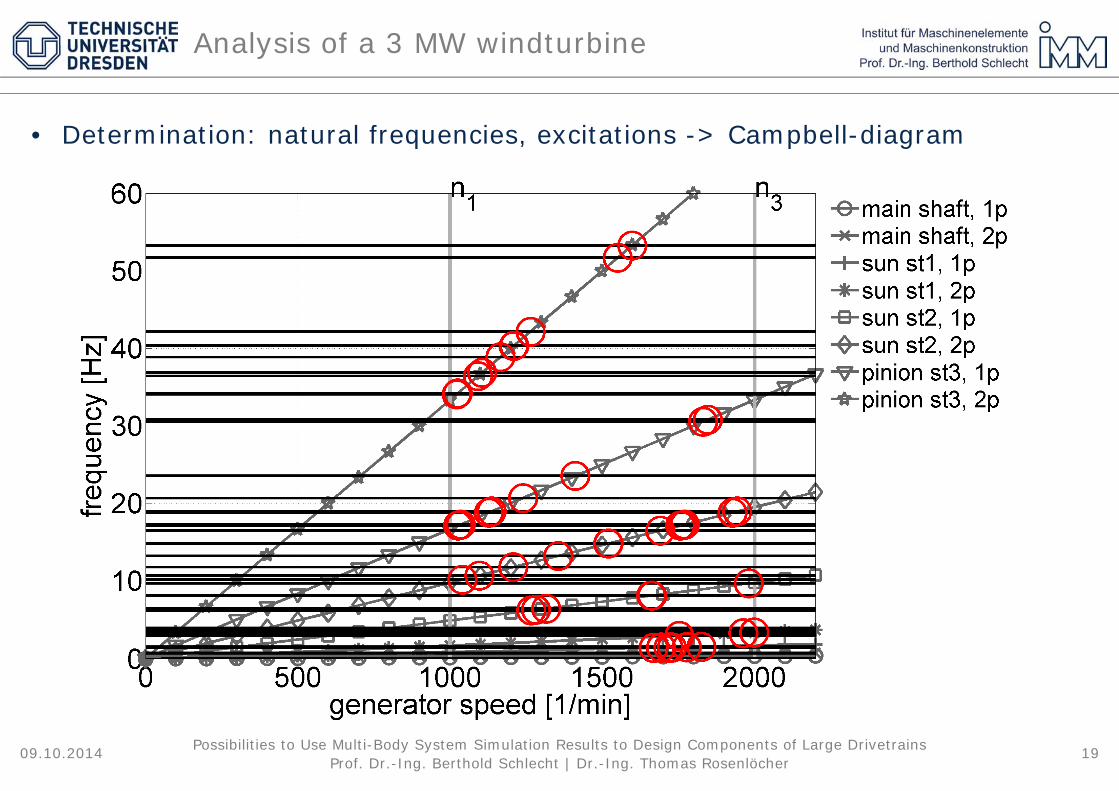
• Determination: natural frequencies, excitations -> Campbell-diagram
09.10.2014 18Possibilities to Use Multi-Body System Simulation Results to Design Components of Large Drivetrains
Analysis of a 3 MW windturbine
Prof. Dr.-Ing. Berthold Schlecht | Dr.-Ing. Thomas Rosenlöcher
• Determination: natural frequencies, excitations -> Campbell-diagram
09.10.2014 19Possibilities to Use Multi-Body System Simulation Results to Design Components of Large Drivetrains
Analysis of a 3 MW windturbine

Prof. Dr.-Ing. Berthold Schlecht | Dr.-Ing. Thomas Rosenlöcher
• Determination: natural frequencies, excitations -> Campbell-diagram
09.10.2014 20Possibilities to Use Multi-Body System Simulation Results to Design Components of Large Drivetrains
Analysis of a 3 MW windturbine

Prof. Dr.-Ing. Berthold Schlecht | Dr.-Ing. Thomas Rosenlöcher
• Detailed analysis of the excitation behaviour• Slow run up of the wind turbine, calculation of the frequency spectrum• Rotatory acceleration of the sun shaft, stage 2
09.10.2014 21Possibilities to Use Multi-Body System Simulation Results to Design Components of Large Drivetrains
Analysis of a 3 MW windturbine
gear mesh frequency, stage 3, 1st order
gear mesh frequency, stage 2, 1st order
gear mesh frequency, stage 2, 2nd order
gear mesh frequency, stage 2, 3rd order

Prof. Dr.-Ing. Berthold Schlecht | Dr.-Ing. Thomas Rosenlöcher09.10.2014 22Possibilities to Use Multi-Body System Simulation Results to Design Components of Large Drivetrains
Analysis of a 3 MW windturbine

Prof. Dr.-Ing. Berthold Schlecht | Dr.-Ing. Thomas Rosenlöcher09.10.2014 23Possibilities to Use Multi-Body System Simulation Results to Design Components of Large Drivetrains
Analysis of a 3 MW windturbine
Prof. Dr.-Ing. Berthold Schlecht | Dr.-Ing. Thomas Rosenlöcher
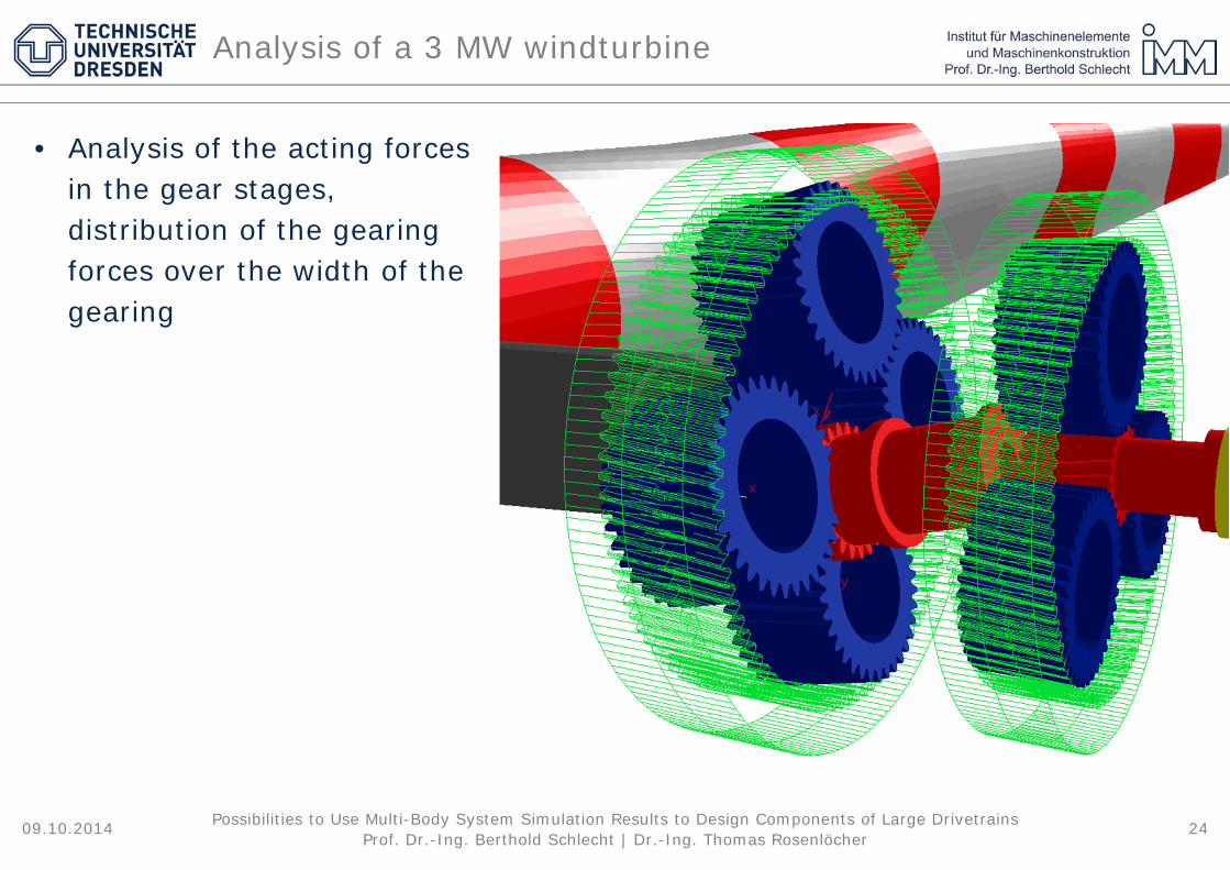
• Analysis of the acting forces in the gear stages, distribution of the gearing forces over the width of the gearing
09.10.2014 24Possibilities to Use Multi-Body System Simulation Results to Design Components of Large Drivetrains
Analysis of a 3 MW windturbine

Prof. Dr.-Ing. Berthold Schlecht | Dr.-Ing. Thomas Rosenlöcher
• Analysis of the acting forces in the gear stages, distribution of the gearing forces over the width of the gearing
• Gear stage 1, contact between sun and one planet• Presentation of the gearing forces for one revolution of the planet carrier
09.10.2014 25Possibilities to Use Multi-Body System Simulation Results to Design Components of Large Drivetrains
Analysis of a 3 MW windturbine
Weight of the rotor neglected
Analysis for nominal load
Weight of hub and rotor blades considered
Analysis for nominal load
forc
e [m
]
forc
e [m
]

Prof. Dr.-Ing. Berthold Schlecht | Dr.-Ing. Thomas Rosenlöcher
• Analysis of the acting forces in the gear stages, distribution of the gearing forces over the width of the gearing
• Gear stage 1, contact between sun and one planet• Presentation of the gearing forces for one revolution of the planet carrier
09.10.2014 26Possibilities to Use Multi-Body System Simulation Results to Design Components of Large Drivetrains
Analysis of a 3 MW windturbine
Weight of hub and rotor blades considered
Analysis for nominal load
Weight of hub and rotor blades considered
Additional modelling of the wind loads
forc
e [m
]
forc
e [m
]

Prof. Dr.-Ing. Berthold Schlecht | Dr.-Ing. Thomas Rosenlöcher
• Simulation model must represent all relevant system properties with sufficient accuracy
• Modelling approach has to adapt to the design of the drivetrain
• Knowledge of the correct system boundaries often requires a very detailed simulation model
• Although torsional vibration models suffice for many analyses, the larger modelling effort required for detailed 3D MBS simulation is often necessary
09.10.2014 27Possibilities to Use Multi-Body System Simulation Results to Design Components of Large Drivetrains
Conclusion

Prof. Dr.-Ing. Berthold Schlecht | Dr.-Ing. Thomas Rosenlöcher
Technische Universität Dresden
Department of Mechanical Engineering
Institute of Machine Elements and Machine Design
Chair of Machine Elements
Münchner Platz 3D-01062 Dresden
www.tu-dresden.de/me
Thank You for Your Attention
09.10.2014 28Possibilities to Use Multi-Body System Simulation Results to Design Components of Large Drivetrains


