POSITIONER APPLICATION NOTE VERSION 1 - · PDF fileOrganisation Européenne de...
22
Organisation Européenne de Télécommunications par Satellite European Telecommunications Satellite Organization 70, rue Balard — 75502 PARIS Cedex 15 — France This document is provided for information purposes. Whilst every effort has been made to provide accurate information, no responsibility is taken for errors or omissions. EUTELSAT reserves the right to change this information without notice. March 15, 1998 Digital Satellite Equipment Control (DiSEqC™) POSITIONER APPLICATION NOTE VERSION 1.0
Transcript of POSITIONER APPLICATION NOTE VERSION 1 - · PDF fileOrganisation Européenne de...

Organisation Européenne de Télécommunications par SatelliteEuropean Telecommunications Satellite Organization
70, rue Balard — 75502 PARIS Cedex 15 — France
March 15, 1998
Digital Satellite Equipment Control (DiSEqC™)
POSITIONER APPLICATION NOTE
VERSION 1.0
This document is provided for information purposes. Whilst every effort has been made to provide accurate information, no responsibility is taken for errors or omissions. EUTELSAT reserves the right to change this information without notice.

Positioner Application Note Version 1.0
Digital Satellite Equipment Control (DiSEqC)
998)
d
Reference Documents that define the DiSEqC System:
DiSEqC™ Bus Specification Version 4.2 (February 25, 1998)
DiSEqC™ Slave Microcontroller Specification Version 1.0 (February 25, 1998)
DiSEqC™ Logos and Their Conditions of Use (February 25, 1998)
Associated Documents:
Update and Recommendations for Implementation Version 2.1 (February 25, 1
Application Information for using a "PIC" Microcontroller in DiSEqC™ LNB ansimple switcher Applications Version 1.0 (June 7, 1999)
Application Information for Tuner-Receiver/IRDs (April 12, 1996)
Application Information for LNBs and Switchers Version 2 (February 25, 1998)
Reset Circuits for the Slave Microcontroller (August 12, 1996)
Simple Tone Burst Detection Circuit (August 12, 1996)
Positioner Application Note Version 1.0 (March 15, 1998)
page II March 15, 1998 POSITION.TIT

CONTENTS
Positioner Application Note Version 1.0
Digital Satellite Equipment Control (DiSEqC)
. . 3
. . . 4
. . 6
. . 7
. . 7
. . 8
. . 8
. . 9
. . . 9
. 10
. 10
. . 11
. . 13
. 15
. 16
1. Introduction . . . . . . . . . . . . . . . . . . . . . . . . . . . . . . . . . . . . . . . . . . . . . . . . . 1
2. General Application Considerations . . . . . . . . . . . . . . . . . . . . . . . . . . . . . 12.1. Power Availability . . . . . . . . . . . . . . . . . . . . . . . . . . . . . . . . . . . . . . . . 2
2.2. Direction of Antenna-shaft Rotation . . . . . . . . . . . . . . . . . . . . . . . . . . 3
2.3. “Endstop” Operation. . . . . . . . . . . . . . . . . . . . . . . . . . . . . . . . . . . . .
2.4. Mechanical Alignment . . . . . . . . . . . . . . . . . . . . . . . . . . . . . . . . . .
3. Positioner Commands . . . . . . . . . . . . . . . . . . . . . . . . . . . . . . . . . . . . . . . . . 53.1. “Halt Motor”. . . . . . . . . . . . . . . . . . . . . . . . . . . . . . . . . . . . . . . . . . .
3.2. “Disable (soft) Limits” . . . . . . . . . . . . . . . . . . . . . . . . . . . . . . . . . . .
3.3. “Set East (soft) Limit” . . . . . . . . . . . . . . . . . . . . . . . . . . . . . . . . . . .
3.4. “Set West (soft) Limit”. . . . . . . . . . . . . . . . . . . . . . . . . . . . . . . . . . .
3.5. “Drive Motor East”. . . . . . . . . . . . . . . . . . . . . . . . . . . . . . . . . . . . . .
3.6. “Drive Motor West” . . . . . . . . . . . . . . . . . . . . . . . . . . . . . . . . . . . .
3.7. “Store Satellite Position” . . . . . . . . . . . . . . . . . . . . . . . . . . . . . . . .
3.8. “Goto Satellite Position”. . . . . . . . . . . . . . . . . . . . . . . . . . . . . . . . . .
3.9. “(Re-) Calculate Satellite Positions” . . . . . . . . . . . . . . . . . . . . . . . .
3.10. “Goto Angular Position (degrees)”. . . . . . . . . . . . . . . . . . . . . . . . .
3.11. Read Positioner Status Byte (Level 2.2) . . . . . . . . . . . . . . . . . . . .
4. User Interface . . . . . . . . . . . . . . . . . . . . . . . . . . . . . . . . . . . . . . . . . . . . . . . 134.1. Typical “Installer” Command Menu . . . . . . . . . . . . . . . . . . . . . . . .
4.2. Typical “User” Command Menu . . . . . . . . . . . . . . . . . . . . . . . . . . .
5. Positioner Units Embedded Software. . . . . . . . . . . . . . . . . . . . . . . . . . . . 17
6. Contact Details . . . . . . . . . . . . . . . . . . . . . . . . . . . . . . . . . . . . . . . . . . . . . . 20
page III March 15, 1998 POSITION.TDM

Positioner Application Note Version 1.0
Digital Satellite Equipment Control (DiSEqC)
ner-e isr thehe
od of
r the
ioneremote
ore
toe tors to.2”o ifaster
, andsh)cted
cable thelUnit
1. Introduction
The DiSEqC system provides a method of controlling a wide range ofaccessories usually located at, or near, a satellite-receiving antenna (dish). Ituses the existing I.F. coaxial cable (“downlead”) which connects to the Tureceiver, or Integrated Receiver Decoder (IRD). This Application Notconcerned with the definition and application of a group of commands, focontrol of a “Positioner” Motor Unit, which can automatically rotate treceiving antenna to individually point at one from a range of satellites.
The specification of the basic hardware characteristics, and the methsignalling on the satellite downlead cable are defined in the Bus FunctionalSpecification Version 4.2. This version includes a modified list of “PositioneCommands”, which have been adapted to suit “one-way” operation onBus. These commands allow the Tuner-receiver/IRD to control the Positwithout any necessity to receive reply or data messages back from the rmotor unit. However, implementation of reply messages can give mreliable operation and simplify installation.
A new DiSEqC Implementation Level (level 1.2) has been introducedsupport Positioner applications. Tuner-receiver/IRDs must be abltransmit at least the basic set of “mandatory” commands for Positionequalify for using the “1.2” Logo. Positioner Motor Units may use the “1Logo if they support the basic positioner commands, and the “2.2” Logthey return appropriate “Reply” messages when requested by the M(Tuner-receiver/IRD).
2. General Application Considerations
A minimum DiSEqC Positioner system need consists only of a DiSEqCLevel 1.2 Tuner-receiver/IRD connected at the lower end of the I.F. cablea DiSEqC Positioner Motor Unit fixed between the satellite antenna (diand the antenna mount. The Positioner Motor Unit has two interconne(unswitched) connectors, one for the downlead and the other for a shortto the LNB. Thus, I.F. signals pass down from the LNB to the receiver viaMotor Unit. Power and DiSEqC (and/or backwards-compatible) controsignals pass from the Tuner-receiver/IRD up to, and through, the Motor to the LNB.
page 1 March 15, 1998 POSITION.FRM

Positioner Application Note Version 1.0
Digital Satellite Equipment Control (DiSEqC)
obal” 13
is a) tomayake
the
astcallyr theion Bus
t they beveuntakend
g)
unit.line)y as the
re inwouldrentolutenals
n theporter-
Normally, to give backwards compatibility, Tuner-receiver/IRDs willtransmit a 13/18 volt d.c. level on the bus in concord with the Polarisation datacarried in the DiSEqC messages. However, at least for DiSEqCImplementation Levels above 1.0, there is an advantage if the d.c. level canbe selected independently of the Polarisation. This need only be a “gloption, i.e. the d.c. voltage either follows the Polarisation, or is alwaysvolts or always 18 volts, for all channels. For SMATV applications therepreference to fix the bus d.c. voltage low (i.e. approximately 13 voltseconomise on power dissipation. However, for Positioner applications it be preferable to use a higher voltage (i.e. approximately 18 volts) to mmore power available to the motor, so that it can drive more quickly torequired position.
2.1. Power Availability
DiSEqC Tuner-receiver/IRDs are required to be able to deliver at le500 mA d.c. onto the bus to power all the peripheral components. Typithere may be a maximum current of about 350 mA available to powePositioner Motor Unit. Motor units intended for this basic type of installatshould thus incorporate circuitry to ensure that the current taken from thedoes not exceed about 400 mA. even when the motor is stalled.
A current limit of 400 mA obviously places a restriction on the speed thamotor unit can move the antenna dish, so alternative configurations maworthy of consideration. Although the Positioner Motor Unit could remopower from the LNB while traversing, this would only make a small amoof additional current available, and is not recommended. It would moptimisation of the signal strength (manual or automatic) difficult arequires that DiSEqC-only LNBs must be sent new status (switchincommands when their power is restored.
One solution is to make an additional power feed available to the motorProbably this would be derived from a local (e.g. roof-space) mains (power supply. It would need some additional cabling, but not generallmuch as is required to route normal Positioner control cables down tolocation of the Tuner-receiver/IRD.
A more versatile approach is to apply a “d.c. Power Booster” somewhethe downlead, perhaps close to the Tuner-receiver/IRD. Such a booster take power from a local mains (line) supply and make additional curavailable to pass up the cable to the Positioner Motor Unit. The absminimum requirement for such a booster is to be “transparent” to I.F. sigpassing down the cable (from the LNB) and 22 kHz modulated (DiSEqC)signals passing up the cable. However, to avoid application problems ifield, it is strongly recommended that any such unit should also sup“backwards-compatible” 13/18 volt (polarisation) signalling from the Tun
page 2 March 15, 1998 POSITION.FRM
Positioner Application Note Version 1.0
Digital Satellite Equipment Control (DiSEqC)
ents mayfor the
ble,ionerNB” used
ired. the
fhernf thethernnti-r to
o be-overy be
receiver/IRD to the LNB and DiSEqC “Reply” messages back from thLNB and/or Positioner Motor Unit to the Tuner-receiver. Note that if curresignificantly higher than 500 mA are to be passed up the cable, then itbe necessary to include some (adjustable) pre-compensation to correct voltage drop across the resistance of the cable.
Another possibility is to apply a degree of “voltage boosting” on the caperhaps up to the 36 volts commonly used by separately-wired positsystems. In this case the motor unit must drop the voltage to its “Lconnector back to the normal d.c. level, and various techniques could beto reproduce the backwards-compatible 13/18 volts signalling, if requHowever, it is important that the Positioner Motor Unit, Booster Unit anduser-documentation must carry clear labels that normal DiSEqC and otheraccessories are only to be connected onto sockets marked “LNB”.
2.2. Direction of Antenna-shaft Rotation
For clarity in the DiSEqC specification, the direction of movement oantenna Positioners is described as “East” or “West”. In the northemisphere Westerly movement corresponds to clockwise rotation oantenna drive shaft when viewed from the top. For use in the souhemisphere the equivalent direction of motor rotation would be aclockwise, so it will be necessary to modify the embedded software oreverse the motor connections. If a Positioner Motor Unit is intended tused in either hemisphere then the preferred solution is to fit a changeswitch, but the provision of alternative alignment tables or charts maadequate.
2.3. “Endstop” Operation
It is important that Positioner Motor Units should not damage themselves, orany part of the mount or antenna, if instructed to drive continuously in eitherdirection (even under fault or error conditions). If the power available to themotor is limited to that defined for the standard DiSEqC Bus (i.e. about 6watts) then there is unlikely to be sufficient torque to cause damage. If it hasa particularly high gear ratio, then it may be beneficial to include some formof slipping clutch mechanism, or limiting mechanism as described below. Itis better to locate the clutch in the drive train between the motor and the shaft-rotation detector, so that the system alignment (i.e. the satellite positions) isnot disturbed if the clutch slips.
page 3 March 15, 1998 POSITION.FRM

Positioner Application Note Version 1.0
Digital Satellite Equipment Control (DiSEqC)
imitotor
torpast tosed
Halt”bled”them.ser-
d on motor soft
bewithh, inaller
ent. theg theumr the
ft andn.
) ofa true thener
n orthe
If additional power is available to the motor unit, then an active method ofpreventing damage to the system may be required. This normally takes theform of moveable switches (e.g. micro-switches) which can be set todisconnect power before the antenna or internal drive mechanism reaches anyphysical limit such as a wall or the end of a “leadscrew”. These “Hard LSwitches” are adjusted when the complete antenna and positioner massembly are being installed on their mountings.
Another form of endstop is “Soft(ware) Limits” where the positioner mocontrol system stores two positions (the East and West Soft Limits) which it will not normally drive the motor. These may be beneficialprevent the motor unit driving the antenna far away from the normally-uarc of satellites, due to a user or a system error (e.g. a corrupted “command). To allow these Soft Limits to be changed, they can be “disawith a software command, so that the motor can be made to drive past It is suggested that disabling the soft limits should require a specific uaction (e.g. confirming the requirement), but still they should not be relieas the sole method of protecting against damage. This is because theunit and antenna normally will not be in the sight of the user when thelimits are being adjusted.
2.4. Mechanical Alignment
The rotational axis of the Positioner Motor Unit output shaft needs toaligned accurately with the Earth’s polar axis. Initially, this can be done a spirit level (or plumb line) and a magnetic compass to find due soutassociation with data related to the site latitude and longitude. For smdishes, particularly over a fairly small arc of the sky, this may be sufficiHowever, for larger dishes sweeping almost from horizon to horizonalignment needs to be to a fraction of a degree. This requires trimmintilt adjustment at several positions around the full arc to find the maximsignal strength of appropriate satellites. A method of speeding this up foprofessional installer is to release the coupling between the output shathe motor so that the dish can be manually swung from horizon to horizo
An alternative approach is to allow small adjustments of the tilt (elevationthe antenna axis to be made remotely with a small motor (or, of course, azimuth-elevation mount system can be used). This is supported inDiSEqC system by defining two addresses for commands to Positiomotors. Address ‘31’ (hexadecimal) is for the normal equatorial rotatioazimuth, and address ‘32’ (hexadecimal) for trimming the tilt, or “elevation”, of the antenna. More details are given in section 3. and section 4.
page 4 March 15, 1998 POSITION.FRM
Positioner Application Note Version 1.0
Digital Satellite Equipment Control (DiSEqC)
nd ansfer(odd)
er-age.
r, or theTheats (i.e.edevant to the notress
hndsll the
imalse.g.asicem to
ionrr’. Thetheal datamand in the
3. Positioner Commands
Like all DiSEqC command messages, the Positioner control messagesconsist of at least three bytes, a ‘Framing’ byte, an ‘Address’ byte a‘Command’ byte. Some commands have one or more ‘Data’ bytes to traadditional information in the message. Each byte has an associated parity bit for error-detection purposes.
The Framing byte is normally ‘E0’ (hexadecimal) if the master (Tunreceiver/IRD) does not require (or is not able to receive) a “Reply” messIt is usually ‘E2’ to request a Reply.
The normal Address byte for Positioner motors which drive on a polaazimuthal, axis is ‘31’ (hexadecimal). Motors which drive to determine“elevation” (or tilt) of the antenna have an address ‘32’ (hexadecimal). DiSEqC protocol is that a ‘0’ nibble is a “wildcard” (or “don’t care”) so thaddress ‘30’ (hexadecimal) sends commands to all Positioner addresseincluding ‘31’ and ‘32’). Clearly, commands which are specifically intendto produce movement in one axis of a two-axis system must use the reladdress byte. Commands which are relevant to both axes can be sentgeneral (wildcard) address (‘30’). Simple Tuner-receiver/IRDs which dosupport any vertical (tilt) movement should generally use the specific add‘31’ to avoid malfunctioning with a Positioner Motor Unit whicincorporates remote control of tilt. However, very few additional commaare required to support two-axis control, so it is recommended to use acommands with their correct associated addresses, as shown in section 5.
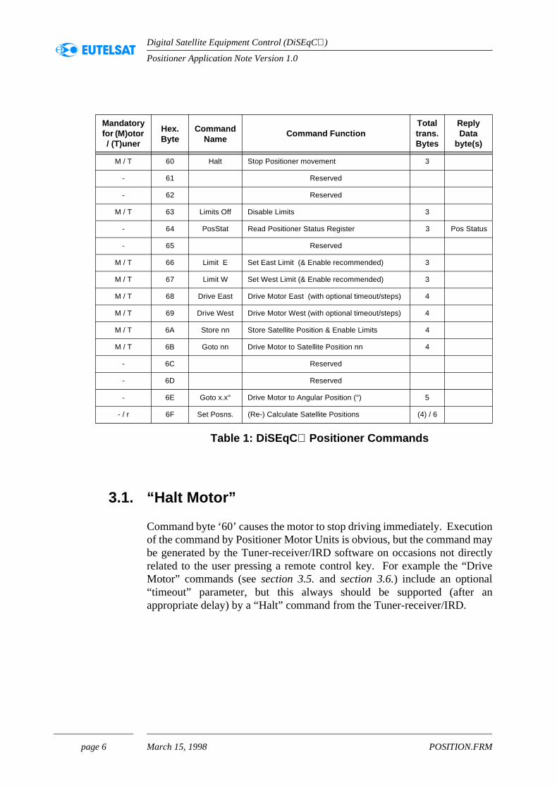
All the Positioner Command bytes defined so far have a ‘high’ hexadecnibble ‘6’ and are shown in Table 1. It is Recommended that all Slave(including Positioners) should support “Level 2.x ” reply messages (“OK”, “Unrecognised Command”, etc.) when requested, but the bcommands do not demand the return of actual data values for the systoperate successfully.
Column 1 in Table 1 indicates which commands are mandatory for inclusin Positioner Motor Units (‘M’) and Tuner-receiver/IRDs (‘T’) to qualify fothe ‘1.2’ (or higher) DiSEqC Logo. The equivalent lower-case letter ‘indicates commands which are recommended for inclusion in these unitspenultimate column (“Total transmitted bytes”) indicates whether message uses just the basic 3 bytes, or whether one or more additionbytes are included in the message. Only one (non-mandatory) comrequests the return of data (the status byte) from the slave, as indicatedfinal column of Table 1.
The following sub-sections describe each command in detail.
page 5 March 15, 1998 POSITION.FRM
Positioner Application Note Version 1.0
Digital Satellite Equipment Control (DiSEqC)
tionmayectlyrive
an
Table 1: DiSEqC Positioner Commands
3.1. “Halt Motor”
Command byte ‘60’ causes the motor to stop driving immediately. Execuof the command by Positioner Motor Units is obvious, but the command be generated by the Tuner-receiver/IRD software on occasions not dirrelated to the user pressing a remote control key. For example the “DMotor” commands (see section 3.5. and section 3.6.) include an optional“timeout” parameter, but this always should be supported (afterappropriate delay) by a “Halt” command from the Tuner-receiver/IRD.
Mandatoryfor (M)otor / (T)uner
Hex. Byte
CommandName
Command FunctionTotaltrans.Bytes
ReplyData
byte(s)
M / T 60 Halt Stop Positioner movement 3
- 61 Reserved
- 62 Reserved
M / T 63 Limits Off Disable Limits 3
- 64 PosStat Read Positioner Status Register 3 Pos Status
- 65 Reserved
M / T 66 Limit E Set East Limit (& Enable recommended) 3
M / T 67 Limit W Set West Limit (& Enable recommended) 3
M / T 68 Drive East Drive Motor East (with optional timeout/steps) 4
M / T 69 Drive West Drive Motor West (with optional timeout/steps) 4
M / T 6A Store nn Store Satellite Position & Enable Limits 4
M / T 6B Goto nn Drive Motor to Satellite Position nn 4
- 6C Reserved
- 6D Reserved
- 6E Goto x.x° Drive Motor to Angular Position (°) 5
- / r 6F Set Posns. (Re-) Calculate Satellite Positions (4) / 6
page 6 March 15, 1998 POSITION.FRM

Positioner Application Note Version 1.0
Digital Satellite Equipment Control (DiSEqC)
and
d orhen andor”
its”.ed)or”otor
s to their
in thes, this?”
East isotor
callythisnit
t will the
it isand
A common User-Interface function is to drive the positioner motor whilst a(remote control) key is held depressed. This facility can be obtained bygenerating a “Drive Motor” command when the key is initially pressed then sending a “Halt” command when the key is released. Note that thisfunction could be implemented in the Remote Control protocol (Infra-ReRadio), by sending separate commands for “start” and “stop” wrespectively pressing and releasing a key. Alternatively, the onsettermination of a stream of repeated Remote Control “Drive Motcommands might be converted to the DiSEqC “Drive” and “Halt”commands in the Tuner-receiver/IRD embedded software.
3.2. “Disable (soft) Limits”
Command byte ‘63’ disables both the East and West “Soft(ware) LimThis allows the positioner motor to drive over the full (mechanically-definarc of its movement, when commanded by the normal “Drive Motcommands. It is not mandatory to support this command in Positioner MUnits, but the command must be available from Tuner-receiver/IRDensure that motor units which do support soft limits can be aligned overfull mechanical range.
It is recommended that the “Disable Limits” command is “protected”Tuner-receiver/IRDs to prevent accidental transmission, particularly bynormal user (as opposed to the installer). In On-Screen-Display systemmay be by including it in an “Installer Menu” and/or with an “Are You Sureprompt or a “PIN” code number.
3.3. “Set East (soft) Limit”
Command byte ‘66’ stores the present position of the motor shaft as the(Soft) Limit, or “endstop”. To avoid accidental changing of the Limit, itrecommended that this command is only executed by the Positioner MUnit when the Limit is at present disabled, and this should then automatienable the Limit. Whether the other (West) Limit is also enabled by command is optional in the implementation of the Positioner Motor Uembedded software. If both Limits are enabled by the command then ibe necessary for another “Disable Limits” command to be sent beforeother (West) Limit can be set. Alternatively, if only the associated Limenabled then it would be necessary to transmit an “Enable Limits” comm(see command byte ‘6A’) if only one Limit was to be changed.
page 7 March 15, 1998 POSITION.FRM

Positioner Application Note Version 1.0
Digital Satellite Equipment Control (DiSEqC)
on Limit
bytemit.
ngthing
y iniver/
F’ notsesmitwhilstes
llersusted by
ps”hey not
f theps 5%me asffect Unit
If limits are “Enabled”, then whenever the motor is driving, it must stopreaching the positions which were stored by the Set East and Set Westcommands.
3.4. “Set West (soft) Limit”
Command byte ‘67’ produces exactly the same behaviour as command‘66’ except that the West Soft Limit is affected instead of the East Soft Li
3.5. “Drive Motor East”
Command byte ‘68’ is used with a following data byte to determine the leof time that the motor drives to the East. The default value for the timparameter byte is ‘00’ for which the Positioner Motor drives continuouslthe required direction. It is mandatory for Master controllers (Tuner-receIRDs) to transmit at least this data value (or any other positive value).
Positive (non-zero) values of the parameter byte (i.e. ‘01’ to ‘7hexadecimal) indicate a “timeout” value in seconds, but Positioner Motorssupporting a timing function should drive continuously if receiving theparameter values. A typical use would be for the Master controller to trana “Go East for 4 seconds” command and repeat it, say, every 3 seconds movement is required. This is “fail safe” if a “Halt” message becomcorrupted (invalidated) on the bus. Note however, that Master contromust still transmit a “Halt” command when movement is to stop, (they mnot rely on the timeout alone), because the timeout may not be supportall Positioner Motor Units.
Negative parameter values (i.e. ‘80h’ to ‘FFh’) indicate the number of “stethe motor should make, and Positioner Motors should only drive if tsupport this movement process. Thus, Positioner Motor Units which dosupport this function should not drive if the Most Significant Bit of theparameter data byte is a ‘1’ (the “negative flag”).
Each “step” will typically correspond to the smallest angular movement oantenna shaft which the associated dish can usefully resolve, i.e. perhato 10% of the beam width of the antenna. This is not necessarily the sathe pulse resolution from the shaft rotation sensor (reed relay, Hall-eswitch, etc.), but these pulses can easily be divided down by the Motorembedded software to the appropriate step value.
page 8 March 15, 1998 POSITION.FRM

Positioner Application Note Version 1.0
Digital Satellite Equipment Control (DiSEqC)
’ two“step”” theving
andoint
68’,est
A 01’ thets ifis notmorea in
encemeo alltingts”tore
The number of steps to make is given by the additional count needed to makethe parameter byte reach zero (or overflow to zero if the byte is considered asunsigned). Thus the byte ‘FF’ (hexadecimal) requests only one step, ‘FEsteps, and for example ‘F9’ requests 7 steps. The advantage of the format of this command is that it much easier and repeatable to “nudgealignment when installing the antenna (or a new satellite) than simply drithe motor for a short time.
In all the above circumstances, if the East (Soft) Limit has been SetEnabled, then the motor should stop driving if it reaches the stored limit pbefore completing the defined task.
3.6. “Drive Motor West”
Command byte ‘69’ with a data byte ‘xx’ is used exactly as command ‘but to drive the Positioner Motor to the West and with reference to the W(Soft) Limit (if Set and Enabled).
3.7. “Store Satellite Position”
Satellite Positions are defined by positive binary number parameters from 1(‘01’ hexadecimal) upwards. Thus the command and parameter bytes ‘6store the present motor position as “Satellite Position 1”. In addition,Positioner Motor Unit embedded software should Enable both (soft) Limithey have been set. The maximum number of positions to be stored defined, but it should not be less than 8. 30 or 40 satellites may be typical, particularly if the motor unit has pre-stored satellite position datits ROM (for automatic installation).
The parameter byte ‘00’ (i.e. Satellite Position 0) is reserved as a “referposition” which is not valid for storing satellite position data. However, soapplications may require a specific command to Enable (Soft) Limits, sMasters (i.e. Tuner-receiver/IRDs) should be capable of transmitcommand ‘6A’ with a data byte ‘00’, either specifically as an “Enable Limiuser-command, or by allowing “Position 0” to be selected for the “SSatellite Position” installation command.
page 9 March 15, 1998 POSITION.FRM

Positioner Application Note Version 1.0
Digital Satellite Equipment Control (DiSEqC)
it to theitiond toicaltortemmes.
tingnce the
tallerasic 00’r ofiven thener
litesayived
ort 3ns”tionlite.g.anyta tootor
3.8. “Goto Satellite Position”
Command byte and parameter ‘6B xx’ causes the Positioner Motor Undrive back at any later time to the antenna shaft position stored byassociated command ‘6A xx’. The parameter byte ‘00’ (i.e. Satellite Pos0) is reserved as a “Reference Position” which will normally correspondue South, but may be the easterly “Hard Limit” (i.e. defined by physswitching within the motor unit) if so implemented in the Positioner MoUnit. The reference position is primarily intended for use during sysinstallation, but may be required for antenna alignment at subsequent ti
All Masters (i.e. Tuner-receiver/IRDs) should be capable of transmitcommand ‘6B’ with a data byte ‘00’, either specifically as a “Goto ReferePosition” user-command, or by allowing “Position 0” to be selected with“Goto Satellite Position” user-command.
3.9. “(Re-) Calculate Satellite Positions”
Command byte ‘6F’ with various data parameters can give the user/insvarious types of “short-cut” to setting up or aligning the system. The bcommand has the (first) parameter byte set to zero, i.e. command ‘6Fwhich can initiate any appropriate function, defined by the manufacturethe Positioner Motor Unit. In general, the user/installer will manually drthe antenna to receive a strong signal from a suitable satellite and thecommand ‘6F 00 {00 00}’ will cause the embedded software in the PositioMotor Unit to calculate the (approximate) positions of all the other satelin its memory (ROM) relative to the known position. The user/installer mthen need to optimise each position in turn with reference to the recesignal strength.
It is preferred that Tuner-receiver/IRDs with Menu systems should supp(signed) binary parameter bytes for the “Calculate Satellite Positiocommand. Again, their exact function will be defined in the documentafor the Positioner Motor Unit, but they typically may be used for, “SatelNumber”, “X-Value” (e.g. Site Longitude in degrees) and “Y-Value” (eSite Latitude in degrees). Thus if the user/installer can receive (identifiable) satellite signal, then the command can contain sufficient dacalculate the positions of all other satellites stored in the Positioner MUnit’s ROM.
page 10 March 15, 1998 POSITION.FRM

Positioner Application Note Version 1.0
Digital Satellite Equipment Control (DiSEqC)
thee can
hose. Inast)
s
es
tastriali or
thed toThea to
in1’
nd thet the
t biteiverional
Strictly, the “X-Value” data byte cannot define a unique Longitude in World because its range is only 256 degrees. However, a suitable rangbe inferred from the range of satellites for which data is stored (i.e. texpected to be above the horizon in the relevant continental region)Europe and Africa the “X-Value” can be signed binary (positive to the Eso that it defines longitudes from 128° West to 127° East. In the Middle Eastand Asia the “X-Value” can be unsigned binary so that it defines longitudefrom 0° to 255° East (i.e. to 105° West). In the Americas the “X-Value”generally would be unsigned binary to the West, so that it defines longitudfrom 0° to 255° West (i.e. to 105° East).
3.10. “Goto Angular Position (degrees)”
Command byte ‘6E’ is not yet fully defined, but will normally use two daparameter bytes. At present the command is defined for control of a terreantenna rotator, e.g. for the azimuth of a horizontally-directed Yagmicrowave antenna.
The high nibble of the first data byte indicates how the remainder ofangular data is to be interpreted. The values ‘F’, ‘0’ and ‘1’ are allocatesupport full rotation in a horizontal plane (e.g. for terrestrial sources). nibble ‘0’ references the angle defined in the remainder of the datNorth (0°), ‘1’ adds 256° clockwise to the angle and ‘F’ subtracts 256°. Thelow nibble of the first data byte indicates the clockwise rotation angleincrements of 16°. Thus a first data byte of ‘00’ defines due North, ‘0defines an azimuth of 16° Εast, ‘0A’ (hexadecimal) an azimuth of 160°, and‘10’ (hexadecimal) a rotation of 256° clockwise from north.
The high nibble of the second data byte defines the angle in degrees, alow nibble indicates the fractional part of a degree, if required. Note thalow nibble is a true binary fraction, and is not Binary Coded Decimal. Thusthe most significant bit (of the low nibble) defines half a degree, the nexa quarter degree and the least significant bit a sixteenth. If the Tuner-recUser-interface is to show a decimal value, then the ten closest fractvalues can be employed, as given in the following table.
page 11 March 15, 1998 POSITION.FRM

Positioner Application Note Version 1.0
Digital Satellite Equipment Control (DiSEqC)
Examples of complete commands for the main points of the compass are:
User-interface
value
Fractional nibble
data value
Actual angle
User-interface
value
Fractional nibble
data value
Actual angle
0.0° 0000 (0h) 0.0000° 0.5° 1000 (8h) 0.5000°
0.1° 0010 (2h) 0.1250° 0.6° 1010 (Ah) 0.6250°
0.2° 0011 (3h) 0.1875° 0.7° 1011 (Bh) 0.6875°
0.3° 0101 (5h) 0.3125° 0.8° 1101 (Dh) 0.8125°
0.4° 0110 (6h) 0.3750° 0.9° 1110 (Eh) 0.8750°
Table 2: Fractional Coding for Decimal Angles
Compass Direction
Backwards Rotation
from North
First Rotationfrom North
Second Rotation
from North
North(0°)
E0 31 6E 00 00(0°)
E0 31 6E 16 80(104+256=360°)
East(90°)
E0 31 6E 05 A0(90°)
E0 31 6E 1C 20(194+256=450°)
South(180°)
E0 31 6E F4 C0(76-256= -180°)
E0 31 6E 0B 40(180°)
West(270°)
E0 31 6E FA 60(166-256= -90°)
E0 31 6E 10 E0(256+14=270°)
Table 3: Sample Azimuth Commands
page 12 March 15, 1998 POSITION.FRM

Positioner Application Note Version 1.0
Digital Satellite Equipment Control (DiSEqC)
’ andthe It is
thener-ver,n to ationsctionaltyle”ner
ut theto a
ver,ps ifo the
3.11. Read Positioner Status Byte (Level 2.2)
The Positioner Status Byte is returned in response to command byte ‘64contains individual flag bits to indicate the operational conditions of software and peripheral hardware related to the Positioner Motor Unit. only relevant in DiSEqC Level 2.2 “two-way” systems.
4. User Interface
The interface that the User has to control the Positioner Motor Unit viaTuner-receiver/IRD will depend on the architecture and design of the Tureceiver, and the (Infra Red or Radio) Remote Control protocol. Howethis section suggests how the required User-functions can be mapped osimple numeric keypad, or an On-Screen Display Menu with about 10 opper screen. The command numbers allocated here are such that the direcommands correlate reasonably with the layout of a normal “telephone skeypad, i.e. a square with ‘1’ in the top left corner, ‘7’ in the bottom left corand ‘0’ below the ‘8’.
Rather more than 10 commands may need to be offered to the “User”, binterface can be simplified and protected by subdividing the functions inspecial “Installer” group and a general-purpose “Viewer” group. Howeeven the “Viewer” commands only need to be used occasionally, perhathe system has become mis-aligned, or to introduce new satellites int
Bit Number Positioner Function
.7 Movement command has been completed
.6 Software Limits are Enabled
.5 Movement direction is (or last was) West
.4 Motor is running
.3 Software Limit (end-stop) has been reached
.2 Power is not available
.1 Hardware switch (Limit or Reference) is activated
.0 Position reference data has been lost or corrupted
Table 4: Positioner Status Byte flag allocations
page 13 March 15, 1998 POSITION.FRM

Positioner Application Note Version 1.0
Digital Satellite Equipment Control (DiSEqC)
ttingnss cankingmenu,ssiblee?”
a long
ftallylimitssary
, thes.
thet this
rsionsf the
memory. Normally, the Tuner-receiver/IRD embedded software generatesthe required commands automatically when the viewer changes theprogramme channel.
The “Installer” group of commands includes those concerned with the seof (Software) Limits and the “Automatic Calculation” of satellite positio(relative to a pre-defined reference). Incorrect use of these commandpotentially upset the functionality of the complete Positioner, perhaps taa considerable time to restore, so it is suggested that either the whole and/or each of these commands individually, should be protected. Potechniques are a “PIN” (Personal Identification Number), an “Are You Surmessage, or a special operation of the Remote Control Keypad such askeypress, or the combined depression of more than one key.
In DiSEqC Level 1.2 “one way” systems (i.e. without a reply) with a “SoLimits” facility it can sometimes be unclear whether the limits are actuenabled or not. It is suggested that commands concerned with these should be transmitted twice by the Tuner-receiver/IRD, to avoid unnecesconfusion if a message is lost due to noise or interference. Similarly“Store Satellite” command is worthy of repetition in all “one way” system
The following sections give a pair of sample menus which include allrecommended commands. There is some duplication of commands, buavoids unnecessary switching between menus, and permits different veof the same command to be included (e.g. “Start” and “Nudge” versions o“Drive Motor” commands).
page 14 March 15, 1998 POSITION.FRM

Positioner Application Note Version 1.0
Digital Satellite Equipment Control (DiSEqC)
e in the
but) sorringther
pply
e-le the thisotober”
faultw” to It iscimalh bytekes are in
and
4.1. Typical “Installer” Command Menu
The “Start Motor” commands normally cause the Positioner Motor to drivthe selected direction until cancelled by the “Halt” command. However,particular data byte shown for the DiSEqC Command in Table 5 is actuallynon-zero to give a “timeout” (if supported by the Positioner Motor Unit), this is nominally set to approximately 64 seconds (‘40’ hexadecimalwould not normally be reached. Note that only the commands refedirectly to East and West motion have the specific address ‘31’. All the ocommands have the “wildcard” address ‘30’ since they might equally ato a motor controlling the vertical (tilt) axis.
Usually, the Limits will be Disabled with key ‘5’ and then automatically rEnabled as each Limit is set. However, the User may accidentally DisabLimits, in which case key ‘8’ can be used to restore them. Note thatcommand is also available on the other (User) menu. Similarly, key ‘7’ (GReference Position) can be supported by the general “Goto Position Numin the User Menu, with position number ‘00’.
The “(Re-) Calculate Positions” command is shown with the basic deparameters, but a more sophisticated Menu system might open a “windoallow the three parameters to be adjusted to suitable decimal values.suggested that the first data byte may take any value defined by the derange 0 to 255, the second byte takes values from -180 to +359 (i.e. eaccan be derived from more than one decimal value) and the third byte tavalue from -128 to +127 decimal. The designer of the embedded softwathe Positioner Motor Unit will have to decide to what extent this commshould be allowed to “overwrite” data which has previously been stored.
Key Command Description Typical DiSEqC Command
1 Start Motor Driving West E1 31 69 40
2 Halt Motor E0 30 60
3 Start Motor Driving East E1 31 68 40
4 Set West (soft) Limit E1 30 67
5 Disable (soft) Limits E0 30 63
6 Set East (soft) Limit E1 30 66
7 Go to Reference Position E0 30 6B 00
8 Enable (soft) Limits E0 30 6A 00
9 (Re-) Calculate Positions E0 30 6F 00 {00 00}
0 Select “User” Menu
Table 5: Typical “Installer” Menu
page 15 March 15, 1998 POSITION.FRM
Positioner Application Note Version 1.0
Digital Satellite Equipment Control (DiSEqC)
tor”out”
ouldally,ost
tive
justedeenges)r theith
uousnce,
4.2. Typical “User” Command Menu
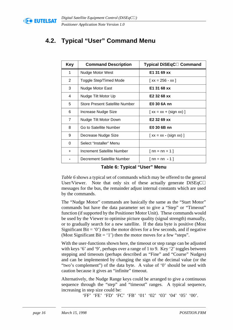
Table 6 shows a typical set of commands which may be offered to the generalUser/Viewer. Note that only six of these actually generate DiSEqCmessages for the bus, the remainder adjust internal constants which are usedby the commands.
The “Nudge Motor” commands are basically the same as the “Start Mocommands but have the data parameter set to give a “Step” or “Timefunction (if supported by the Positioner Motor Unit). These commands wbe used by the Viewer to optimise picture quality (signal strength) manuor to gradually search for a new satellite. If the data byte is positive (MSignificant Bit = ‘0’) then the motor drives for a few seconds, and if nega(Most Significant Bit = ‘1’) then the motor moves for a few “steps”.
With the user-functions shown here, the timeout or step range can be adwith keys ‘6’ and ‘9’, perhaps over a range of 1 to 9. Key ‘2’ toggles betwstepping and timeouts (perhaps described as “Fine” and “Coarse” Nudand can be implemented by changing the sign of the decimal value (o“two’s complement”) of the data byte. A value of ‘0’ should be used wcaution because it gives an “infinite” timeout.
Alternatively, the Nudge Range keys could be arranged to give a continsequence through the “step” and “timeout” ranges. A typical sequeincreasing in step size could be: ‘FF’ ‘FE’ ‘FD’ ‘FC’ ‘FB’ ‘01’ ‘02’ ‘03’ ‘04’ ‘05’ ‘00’.
Key Command Description Typical DiSEqC Command
1 Nudge Motor West E1 31 69 xx
2 Toggle Step/Timed Mode [ xx = 256 - xx ]
3 Nudge Motor East E1 31 68 xx
4 Nudge Tilt Motor Up E2 32 68 xx
5 Store Present Satellite Number E0 30 6A nn
6 Increase Nudge Size [ xx = xx + (sign xx) ]
7 Nudge Tilt Motor Down E2 32 69 xx
8 Go to Satellite Number E0 30 6B nn
9 Decrease Nudge Size [ xx = xx - (sign xx) ]
0 Select “Installer” Menu
+ Increment Satellite Number [ nn = nn + 1 ]
- Decrement Satellite Number [ nn = nn - 1 ]
Table 6: Typical “User” Menu
page 16 March 15, 1998 POSITION.FRM
Positioner Application Note Version 1.0
Digital Satellite Equipment Control (DiSEqC)
the they newe newelliteed toewner-t, if
from
ayed Ther of 1, withldse/ilt”
towillond/or
ta toges
byhenthe few
The other commands permit the User to store the present antenna positionwith reference to the “Satellite Number”, and subsequently causePositioner Motor Unit to drive back to this stored position. In practice,“Go to Satellite Number” DiSEqC Command normally will be generated bthe Tuner-receiver/IRD embedded software when the Viewer selects achannel to watch (or perhaps only when the software determines that thchannel is on a different satellite to that being viewed). The “Store SatNumber” command will usually be used after the antenna has been nudga new position, either to optimise the signal quality, or to install a nsatellite. To prevent accidental corruption of an existing setting, the Tureceiver/IRD embedded software might issue an “Are you sure?” prompthe new location is significantly different (say more than a few degrees) the previously stored value.
The Satellite Number is adjusted in this example menu by the ‘+’ and ‘-’ keyswhich respectively increment and decrement the Satellite Number displin the On-Screen Menu, or on the front panel of the Tuner-receiver/IRD. highest value normally will be defined by the memory capacity (numbe“satellite position” bits) supported by Tuner-receiver. The lowest limit isor perhaps 0 if the Installer Menu does not include the explicit commandsa 00 data byte. If ‘+’ and ‘-’ keys are not available, then the ‘2’ key couinitiate entry of the “Satellite Number” as a numeric value, or the “IncreaDecrease Satellite Number” function could replace the “Step Size” or “Tkey functions.
5. Positioner Units Embedded Software
The Positioner Motor Unit probably will use a single microcontroller perform all the necessary functions within the assembly. Typically, it need to monitor the DiSEqC bus for messages, monitor the motor positi(e.g. by counting pulses from the drive-train) and check for hardware ansoftware “endstops”. At appropriate times it may also need to write dainternal or external Non-Volatile Memory, and to transmit reply messaback to the Master (Tuner-receiver/IRD).
Which of the above functions are initiated by an interrupt and which“polling” (i.e. repeatedly testing the state of a pin or flag, to determine wit changes) will depend on the architecture of the microcontroller, embedded software and the hardware. This section just gives asuggestions for the implementation of the DiSEqC-specific functions.
page 17 March 15, 1998 POSITION.FRM

Positioner Application Note Version 1.0
Digital Satellite Equipment Control (DiSEqC)
ene-t toise”ally
withr) orputn at theform
itherd atimitmumce a
alsosts of
ing/e an
icedg at
ss of Ofn the thish asin the
h the
ia anfter
uiet”
It is possible to detect the DiSEqC data bits modulated onto the 22 kHzcarrier using fairly simple hardware. However, the microcontroller normallywill not be very heavily loaded (in timing or memory size terms), so it shouldbe generally advantageous to detect the data directly from the carrier tone,using real-time software embedded in the microcontroller, as outlined below.
The amplitude of the DiSEqC carrier tone on the bus is generally too smallto detect directly on a “TTL” or “CMOS” compatible pin on thmicrocontroller, so usually a “comparator” input, or a simple external (otransistor) amplifier, will be required. In either case, it is important nomake the input too sensitive to small-amplitude signals which may be “noor interference. It is recommended that the smallest amplitude normdetected is about 300 millivolts peak-peak, which can be achieved eitherhysteresis (positive feedback applied around the comparator/amplifiewith a d.c. bias offset (equivalent to about 150 millivolts) applied to the inof the amplifier/comparator. Hysteresis (if symmetrical) can maintaireasonably constant 50% duty cycle for the detected carrier tone, whilsd.c. offset approach may generate a rather asymmetric (pulse) wavewhen the carrier amplitude approaches the lower limit.
DiSEqC messages can be demodulated directly from the carrier using ean interrupt or a polling structure. Direct polling needs to be performeabove a 50 kHz rate to avoid missing any half-cycles of the upper-lcarrier frequency (26.4 kHz), even if the detected carrier is near the opti50% duty cycle. Servicing direct interrupts at the carrier rate can introdusignificant time overhead (entering and exiting the service routine), andneeds a “timer” to be available to measure the pauses between burcarrier, and to exit at the end of each message.
With some microcontrollers it is possible to use a compromise pollinterrupt arrangement. The carrier tone on the bus is arranged to drivedge-triggered interrupt input. However, the interrupt is not directly serv(i.e. it is disabled), but a polling routine tests the associated interrupt flaabout a 17.5 kHz rate (i.e. just below the minimum carrier frequency). Thus,if the carrier is present then the routine always finds the flag set (regardlethe carrier frequency), and if there is no carrier then the flag is clear.course, the interrupt flag must be repetitively cleared, either by software ipolling routine, or automatically when the flag is read. An advantage ofcontinuous polling technique is that the other status information sucdriveshaft rotation and endstop operation can be economically included polling loop.
Sometimes it is necessary to perform an action which is incompatible witcontinuous polling loop, for example decoding a DiSEqC message, sendinga reply, or sending data to the Non-Volatile memory (perhaps external, vIIC Bus). However, these actions are normally required immediately areceiving a DiSEqC message, when the bus can be assumed to be “qfor at least five milliseconds, and usually much longer.
page 18 March 15, 1998 POSITION.FRM

Positioner Application Note Version 1.0
Digital Satellite Equipment Control (DiSEqC)
When actually transmitting a reply message, it is not necessary to read datafrom the bus, so a separate, accurately-timed, program loop can be arrangedto transmit the data and to poll any urgent status data (i.e. that which maychange again during the 13 or 27 ms period of a typical reply message).
The basic requirements and characteristics of receiving and transmittingmessages over the DiSEqC bus are described in the Bus FunctionalSpecification Version 4.2. Also, an indication of a typical set of commands tobe supported, their validation, and particularly the protocol for transmittingReply messages, may be found in the specification for the Slavemicrocontroller version 1.0, published by EUTELSAT. However, thelikelihood of there being multiple Positioners, with the same address, on thebus is low, so it is probably not necessary to include the random delayarbitration protocol incorporated in the general-purpose Slave. A simplefixed delay of typically 10 ms between the end of the command and the startof the reply may be satisfactory.
page 19 March 15, 1998 POSITION.FRM