
PosiGlaze PG120/180 Balustrade System Design Tables Issue ...
33
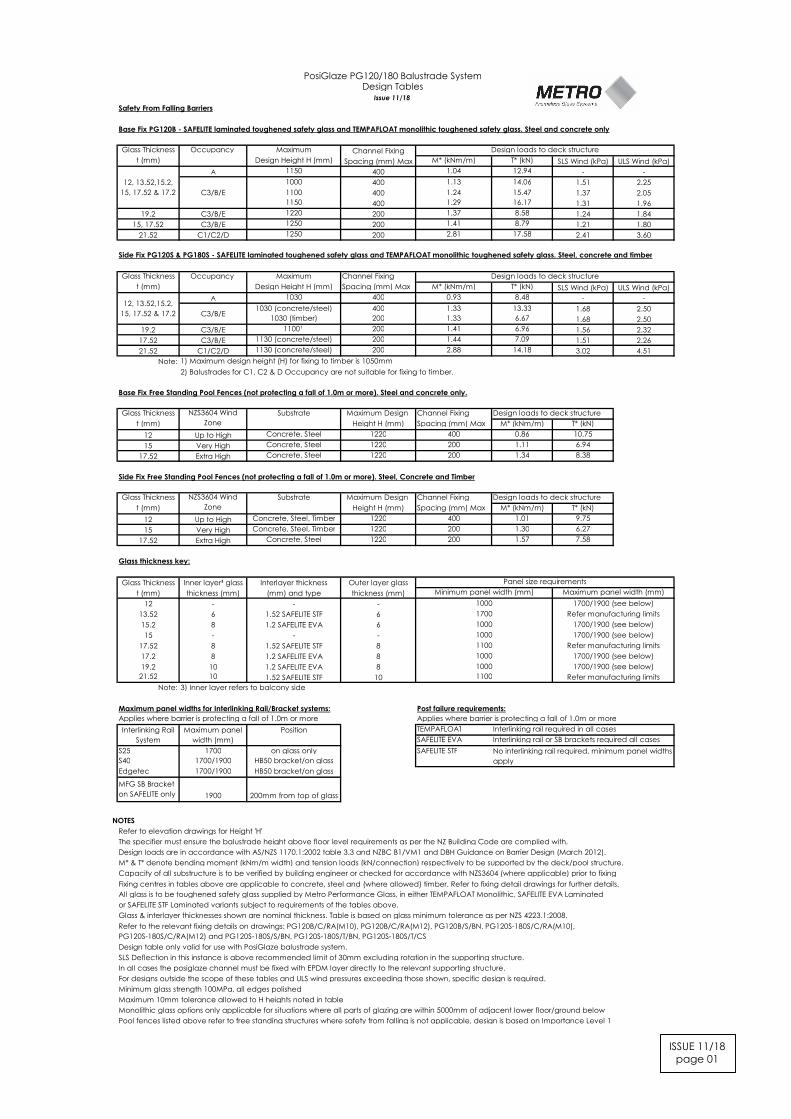
Safety From Falling Barriers Base Fix PG120B - SAFELITE laminated toughened safety glass and TEMPAFLOAT monolithic toughened safety glass. Steel and concrete only Glass Thickness Occupancy Maximum Channel Fixing t (mm) Design Height H (mm) Spacing (mm) Max M* (kNm/m) T* (kN) SLS Wind (kPa) ULS Wind (kPa) A 1150 400 1.04 12.94 - - 1000 400 1.13 14.06 1.51 2.25 1100 400 1.24 15.47 1.37 2.05 1150 400 1.29 16.17 1.31 1.96 19.2 C3/B/E 1220 200 1.37 8.58 1.24 1.84 15, 17.52 C3/B/E 1250 200 1.41 8.79 1.21 1.80 21.52 C1/C2/D 1250 200 2.81 17.58 2.41 3.60 Side Fix PG120S & PG180S - SAFELITE laminated toughened safety glass and TEMPAFLOAT monolithic toughened safety glass. Steel, concrete and timber Glass Thickness Occupancy Maximum Channel Fixing t (mm) Design Height H (mm) Spacing (mm) Max M* (kNm/m) T* (kN) SLS Wind (kPa) ULS Wind (kPa) A 1030 400 0.93 8.48 - - 1030 (concrete/steel) 400 1.33 13.33 1.68 2.50 1030 (timber) 200 1.33 6.67 1.68 2.50 19.2 C3/B/E 1100¹ 200 1.41 6.96 1.56 2.32 17.52 C3/B/E 1130 (concrete/steel) 200 1.44 7.09 1.51 2.26 21.52 C1/C2/D 1130 (concrete/steel) 200 2.88 14.18 3.02 4.51 Note: 1) Maximum design height (H) for fixing to timber is 1050mm 2) Balustrades for C1, C2 & D Occupancy are not suitable for fixing to timber. Base Fix Free Standing Pool Fences (not protecting a fall of 1.0m or more). Steel and concrete only. Glass Thickness Substrate Maximum Design Channel Fixing Design loads to deck structure t (mm) Height H (mm) Spacing (mm) Max M* (kNm/m) T* (kN) 12 Up to High Concrete, Steel 1220 400 0.86 10.75 15 Very High Concrete, Steel 1220 200 1.11 6.94 17.52 Extra High Concrete, Steel 1220 200 1.34 8.38 Side Fix Free Standing Pool Fences (not protecting a fall of 1.0m or more). Steel, Concrete and Timber Glass Thickness Substrate Maximum Design Channel Fixing Design loads to deck structure t (mm) Height H (mm) Spacing (mm) Max M* (kNm/m) T* (kN) 12 Up to High Concrete, Steel, Timber 1220 400 1.01 9.75 15 Very High Concrete, Steel, Timber 1220 200 1.30 6.27 17.52 Extra High Concrete, Steel 1220 200 1.57 7.58 Glass thickness key: Glass Thickness Inner layer³ glass Interlayer thickness Outer layer glass t (mm) thickness (mm) (mm) and type thickness (mm) 12 - - - 13.52 6 1.52 SAFELITE STF 6 15.2 8 1.2 SAFELITE EVA 6 15 - - - 17.52 8 1.52 SAFELITE STF 8 17.2 8 1.2 SAFELITE EVA 8 19.2 10 1.2 SAFELITE EVA 8 21.52 10 1.52 SAFELITE STF 10 Note: 3) Inner layer refers to balcony side Maximum panel widths for Interlinking Rail/Bracket systems: Post failure requirements: Applies where barrier is protecting a fall of 1.0m or more Applies where barrier is protecting a fall of 1.0m or more TEMPAFLOAT Interlinking rail required in all cases SAFELITE EVA Interlinking rail or SB brackets required all cases S25 1700 on glass only SAFELITE STF S40 1700/1900 HB50 bracket/on glass Edgetec 1700/1900 HB50 bracket/on glass MFG SB Bracket on SAFELITE only 1900 200mm from top of glass NOTES Refer to elevation drawings for Height 'H' The specifier must ensure the balustrade height above floor level requirements as per the NZ Building Code are complied with. Design loads are in accordance with AS/NZS 1170.1:2002 table 3.3 and NZBC B1/VM1 and DBH Guidance on Barrier Design (March 2012). M* & T* denote bending moment (kNm/m width) and tension loads (kN/connection) respectively to be supported by the deck/pool structure. Capacity of all substructure is to be verified by building engineer or checked for accordance with NZS3604 (where applicable) prior to fixing Fixing centres in tables above are applicable to concrete, steel and (where allowed) timber. Refer to fixing detail drawings for further details. All glass is to be toughened safety glass supplied by Metro Performance Glass, in either TEMPAFLOAT Monolithic, SAFELITE EVA Laminated or SAFELITE STF Laminated variants subject to requirements of the tables above. Glass & interlayer thicknesses shown are nominal thickness. Table is based on glass minimum tolerance as per NZS 4223.1:2008. Design table only valid for use with PosiGlaze balustrade system. SLS Deflection in this instance is above recommended limit of 30mm excluding rotation in the supporting structure. In all cases the posiglaze channel must be fixed with EPDM layer directly to the relevant supporting structure. For designs outside the scope of these tables and ULS wind pressures exceeding those shown, specific design is required. Minimum glass strength 100MPa, all edges polished Maximum 10mm tolerance allowed to H heights noted in table Monolithic glass options only applicable for situations where all parts of glazing are within 5000mm of adjacent lower floor/ground below Pool fences listed above refer to free standing structures where safety from falling is not applicable, design is based on Importance Level 1 1000 1700/1900 (see below) Panel size requirements C3/B/E PosiGlaze PG120/180 Balustrade System Design Tables Issue 11/18 Design loads to deck structure Design loads to deck structure 12, 13.52,15.2, 15, 17.52 & 17.2 12, 13.52,15.2, 15, 17.52 & 17.2 C3/B/E NZS3604 Wind Zone NZS3604 Wind Zone 1100 Refer manufacturing limits 1700/1900 (see below) 1700/1900 (see below) Refer manufacturing limits Minimum panel width (mm) Refer to the relevant fixing details on drawings: PG120B/C/RA(M10), PG120B/C/RA(M12), PG120B/S/BN, PG120S-180S/C/RA(M10), PG120S-180S/C/RA(M12) and PG120S-180S/S/BN, PG120S-180S/T/BN, PG120S-180S/T/CS Maximum panel width (mm) No interlinking rail required, minimum panel widths apply Interlinking Rail System Maximum panel width (mm) 1100 1000 1700/1900 (see below) Refer manufacturing limits 1700/1900 (see below) 1000 1700 1000 1000 Position ISSUE 11/18 page 01
Transcript of PosiGlaze PG120/180 Balustrade System Design Tables Issue ...
Safety From Falling Barriers
Base Fix PG120B - SAFELITE laminated toughened safety glass and TEMPAFLOAT monolithic toughened safety glass. Steel and concrete only
Glass Thickness Occupancy Maximum Channel Fixing
t (mm) Design Height H (mm) Spacing (mm) Max M* (kNm/m) T* (kN) SLS Wind (kPa) ULS Wind (kPa)
A 1150 400 1.04 12.94 - -
1000 400 1.13 14.06 1.51 2.25
1100 400 1.24 15.47 1.37 2.05
1150 400 1.29 16.17 1.31 1.96
19.2 C3/B/E 1220 200 1.37 8.58 1.24 1.84
15, 17.52 C3/B/E 1250 200 1.41 8.79 1.21 1.80
21.52 C1/C2/D 1250 200 2.81 17.58 2.41 3.60
Side Fix PG120S & PG180S - SAFELITE laminated toughened safety glass and TEMPAFLOAT monolithic toughened safety glass. Steel, concrete and timber
Glass Thickness Occupancy Maximum Channel Fixing
t (mm) Design Height H (mm) Spacing (mm) Max M* (kNm/m) T* (kN) SLS Wind (kPa) ULS Wind (kPa)
A 1030 400 0.93 8.48 - -
1030 (concrete/steel) 400 1.33 13.33 1.68 2.50
1030 (timber) 200 1.33 6.67 1.68 2.50
19.2 C3/B/E 1100¹ 200 1.41 6.96 1.56 2.32
17.52 C3/B/E 1130 (concrete/steel) 200 1.44 7.09 1.51 2.26
21.52 C1/C2/D 1130 (concrete/steel) 200 2.88 14.18 3.02 4.51
Note: 1) Maximum design height (H) for fixing to timber is 1050mm
2) Balustrades for C1, C2 & D Occupancy are not suitable for fixing to timber.
Base Fix Free Standing Pool Fences (not protecting a fall of 1.0m or more). Steel and concrete only.
Glass Thickness Substrate Maximum Design Channel Fixing Design loads to deck structure
t (mm) Height H (mm) Spacing (mm) Max M* (kNm/m) T* (kN)
12 Up to High Concrete, Steel 1220 400 0.86 10.75
15 Very High Concrete, Steel 1220 200 1.11 6.94
17.52 Extra High Concrete, Steel 1220 200 1.34 8.38
Side Fix Free Standing Pool Fences (not protecting a fall of 1.0m or more). Steel, Concrete and Timber
Glass Thickness Substrate Maximum Design Channel Fixing Design loads to deck structure
t (mm) Height H (mm) Spacing (mm) Max M* (kNm/m) T* (kN)
12 Up to High Concrete, Steel, Timber 1220 400 1.01 9.75
15 Very High Concrete, Steel, Timber 1220 200 1.30 6.27
17.52 Extra High Concrete, Steel 1220 200 1.57 7.58
Glass thickness key:
Glass Thickness Inner layer³ glass Interlayer thickness Outer layer glass
t (mm) thickness (mm) (mm) and type thickness (mm)
12 - - -
13.52 6 1.52 SAFELITE STF 6
15.2 8 1.2 SAFELITE EVA 6
15 - - -
17.52 8 1.52 SAFELITE STF 8
17.2 8 1.2 SAFELITE EVA 8
19.2 10 1.2 SAFELITE EVA 8
21.52 10 1.52 SAFELITE STF 10
Note: 3) Inner layer refers to balcony side
Maximum panel widths for Interlinking Rail/Bracket systems: Post failure requirements:
Applies where barrier is protecting a fall of 1.0m or more Applies where barrier is protecting a fall of 1.0m or more
TEMPAFLOAT Interlinking rail required in all cases
SAFELITE EVA Interlinking rail or SB brackets required all cases
S25 1700 on glass only SAFELITE STF
S40 1700/1900 HB50 bracket/on glass
Edgetec 1700/1900 HB50 bracket/on glass
MFG SB Bracket
on SAFELITE only 1900 200mm from top of glass
NOTES
Refer to elevation drawings for Height 'H'
The specifier must ensure the balustrade height above floor level requirements as per the NZ Building Code are complied with.
Design loads are in accordance with AS/NZS 1170.1:2002 table 3.3 and NZBC B1/VM1 and DBH Guidance on Barrier Design (March 2012).
M* & T* denote bending moment (kNm/m width) and tension loads (kN/connection) respectively to be supported by the deck/pool structure.
Capacity of all substructure is to be verified by building engineer or checked for accordance with NZS3604 (where applicable) prior to fixing
Fixing centres in tables above are applicable to concrete, steel and (where allowed) timber. Refer to fixing detail drawings for further details.
All glass is to be toughened safety glass supplied by Metro Performance Glass, in either TEMPAFLOAT Monolithic, SAFELITE EVA Laminated
or SAFELITE STF Laminated variants subject to requirements of the tables above.
Glass & interlayer thicknesses shown are nominal thickness. Table is based on glass minimum tolerance as per NZS 4223.1:2008.
Design table only valid for use with PosiGlaze balustrade system.
SLS Deflection in this instance is above recommended limit of 30mm excluding rotation in the supporting structure.
In all cases the posiglaze channel must be fixed with EPDM layer directly to the relevant supporting structure.
For designs outside the scope of these tables and ULS wind pressures exceeding those shown, specific design is required.
Minimum glass strength 100MPa, all edges polished
Maximum 10mm tolerance allowed to H heights noted in table
Monolithic glass options only applicable for situations where all parts of glazing are within 5000mm of adjacent lower floor/ground below
Pool fences listed above refer to free standing structures where safety from falling is not applicable, design is based on Importance Level 1
1000 1700/1900 (see below)
Panel size requirements
C3/B/E
PosiGlaze PG120/180 Balustrade SystemDesign Tables
Issue 11/18
Design loads to deck structure
Design loads to deck structure
12, 13.52,15.2,
15, 17.52 & 17.2
12, 13.52,15.2,
15, 17.52 & 17.2
C3/B/E
NZS3604 Wind
Zone
NZS3604 Wind
Zone
1100
Refer manufacturing limits
1700/1900 (see below)
1700/1900 (see below)
Refer manufacturing limits
Minimum panel width (mm)
Refer to the relevant fixing details on drawings: PG120B/C/RA(M10), PG120B/C/RA(M12), PG120B/S/BN, PG120S-180S/C/RA(M10),
PG120S-180S/C/RA(M12) and PG120S-180S/S/BN, PG120S-180S/T/BN, PG120S-180S/T/CS
Maximum panel width (mm)
No interlinking rail required, minimum panel widths
apply
Interlinking Rail
System
Maximum panel
width (mm)
1100
1000 1700/1900 (see below)
Refer manufacturing limits
1700/1900 (see below)1000
1700
1000
1000
Position
ISSUE 11/18page 01

Drawing No.: PG120B/C/RA (M10)
Revision: R10
Fixing Type: PG120 with rod anchor (M10)
Occupancy: A, B, E, C3
Refer to PosiGlaze balustrade system design table for required glass thickness, fixing spacings and fixing loads according to AS/NZS1170.1:2002 for the occupancies listed above.
PosiGlaze PG120BBalustrade System
CONCRETE Fixing Detail
Website www.metroglass.co.nz
H (a
s per
des
ign
tabl
es)
M12 x 24 OD x 2.5mm316 grade SS washer
Hilti HIT-HY 200 + HIT-V-R M10 Grade 316 stainless steel anchor with 90mm embedment into uncracked concrete. Anchors to be installed in accordance with Hilti requirements. For anchors adjacent to corners,
dfirst anchor to be place200mm from edge of concrete.
Concrete building structure to be designed by building engineer tosupport loads as specified on PosiGlaze balustrade system design table.
150m
m M
IN sl
ab th
ickn
ess
(MIN
25M
Pa u
ncra
cked
con
cret
e)
MIN
bar
rier h
eigh
t (re
f NZB
C F
4)
NOTES: Refer to design tables and elevations for post failure requirements. Interlinking rail / clips not shown for clarity.'H' refers to top of barrier.
Glass thickness from Design Table
90mm MIN edge distance
Finished Floor Level
1mm EPDM continuous strip(302101) & continuous evenbearing to be provided
t
Recommended drainageholes - Ø6mm@ 400mm centres
20
Max height of fixing
Structural Slab Level
NOTE: not suitable for fixing toblockwork. Specific EngineeringDesign required.
ISSUE 11/18page 02
Notes:1) Capacity of structure is to be of sufficient strength to support loads M*and T* specified on PosiGlaze balustrade system designtable. Structure capacity to be verified by building engineer prior to fixing balustrade.2) Max loading to comply with AS/NZS 1170.1:2002 Minimum Imposed Actions for Barriers Occupancy, shown at top of drawing,for design in accordance with PosiGlaze balustrade system design table.3) Penetration through a membrane must be completed in accordance with written instructions of the membrane manufacturer.4)No substitution allowed - any variation from the details above and design tables will require specific design.
NOT SUITABLE FOR OCCUPANCY C1/C2, D OR C5
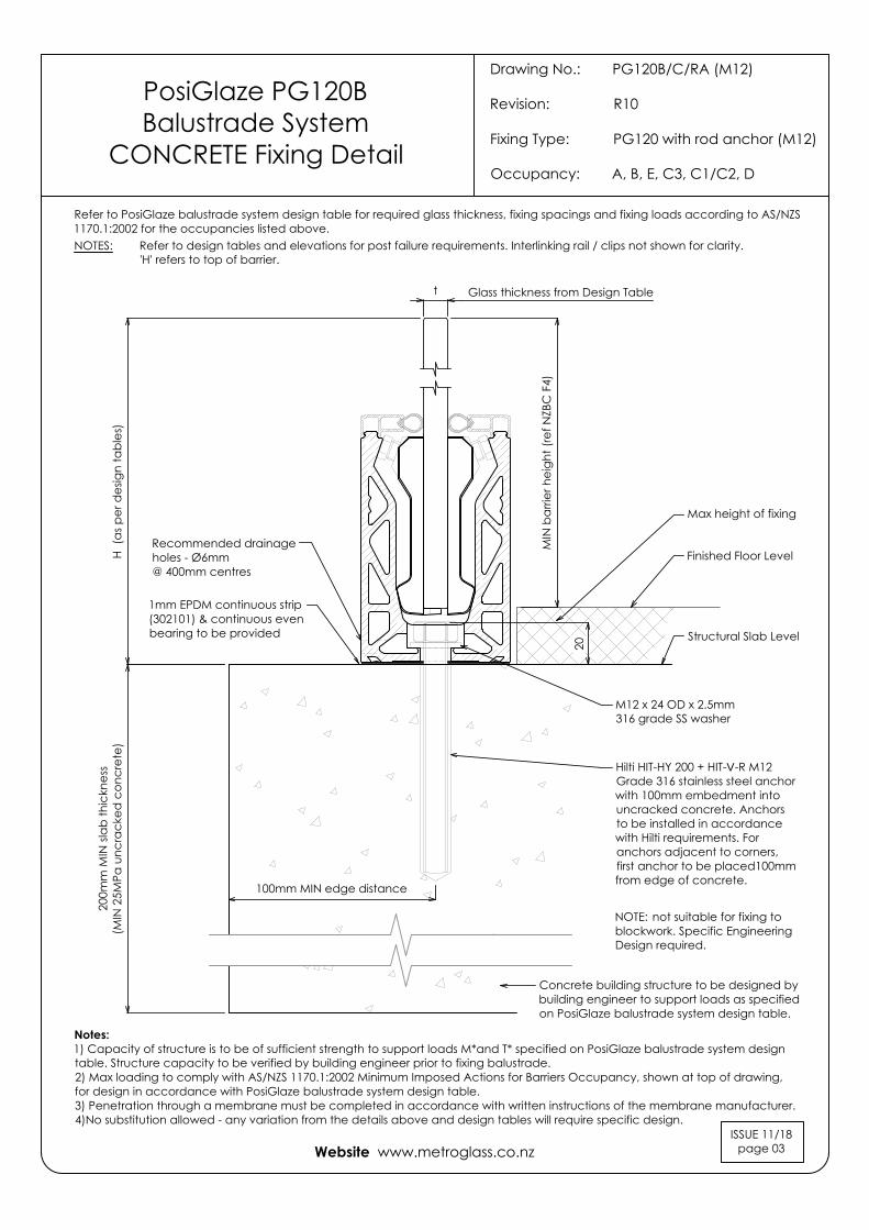
Drawing No.: PG120B/C/RA (M12)
Revision: R10
Fixing Type: PG120 with rod anchor (M12)
Occupancy: A, B, E, C3, C1/C2, D
PosiGlaze PG120BBalustrade System
CONCRETE Fixing Detail
Website www.metroglass.co.nz
200m
m M
IN sl
ab th
ickn
ess
(MIN
25M
Pa u
ncra
cked
con
cret
e)H
(as p
er d
esig
n ta
bles
)
MIN
bar
rier h
eigh
t (re
f NZB
C F
4)
Glass thickness from Design Tablet
100mm MIN edge distance
Recommended drainageholes - Ø6mm@ 400mm centres
M12 x 24 OD x 2.5mm316 grade SS washer
Hilti HIT-HY 200 + HIT-V-R M12 Grade 316 stainless steel anchor with 100mm embedment into uncracked concrete. Anchors to be installed in accordance with Hilti requirements. For anchors adjacent to corners, first anchor to be placed 100mm from edge of concrete.
20
Concrete building structure to be designed bybuilding engineer to support loads as specifiedon PosiGlaze balustrade system design table.
Refer to PosiGlaze balustrade system design table for required glass thickness, fixing spacings and fixing loads according to AS/NZS1170.1:2002 for the occupancies listed above.
NOTE: not suitable for fixing toblockwork. Specific EngineeringDesign required.
ISSUE 11/18page 03
NOTES: Refer to design tables and elevations for post failure requirements. Interlinking rail / clips not shown for clarity.'H' refers to top of barrier.
Finished Floor Level
Max height of fixing
Structural Slab Level
1mm EPDM continuous strip(302101) & continuous evenbearing to be provided
Notes:1) Capacity of structure is to be of sufficient strength to support loads M*and T* specified on PosiGlaze balustrade system designtable. Structure capacity to be verified by building engineer prior to fixing balustrade.2) Max loading to comply with AS/NZS 1170.1:2002 Minimum Imposed Actions for Barriers Occupancy, shown at top of drawing,for design in accordance with PosiGlaze balustrade system design table.3) Penetration through a membrane must be completed in accordance with written instructions of the membrane manufacturer.4)No substitution allowed - any variation from the details above and design tables will require specific design.
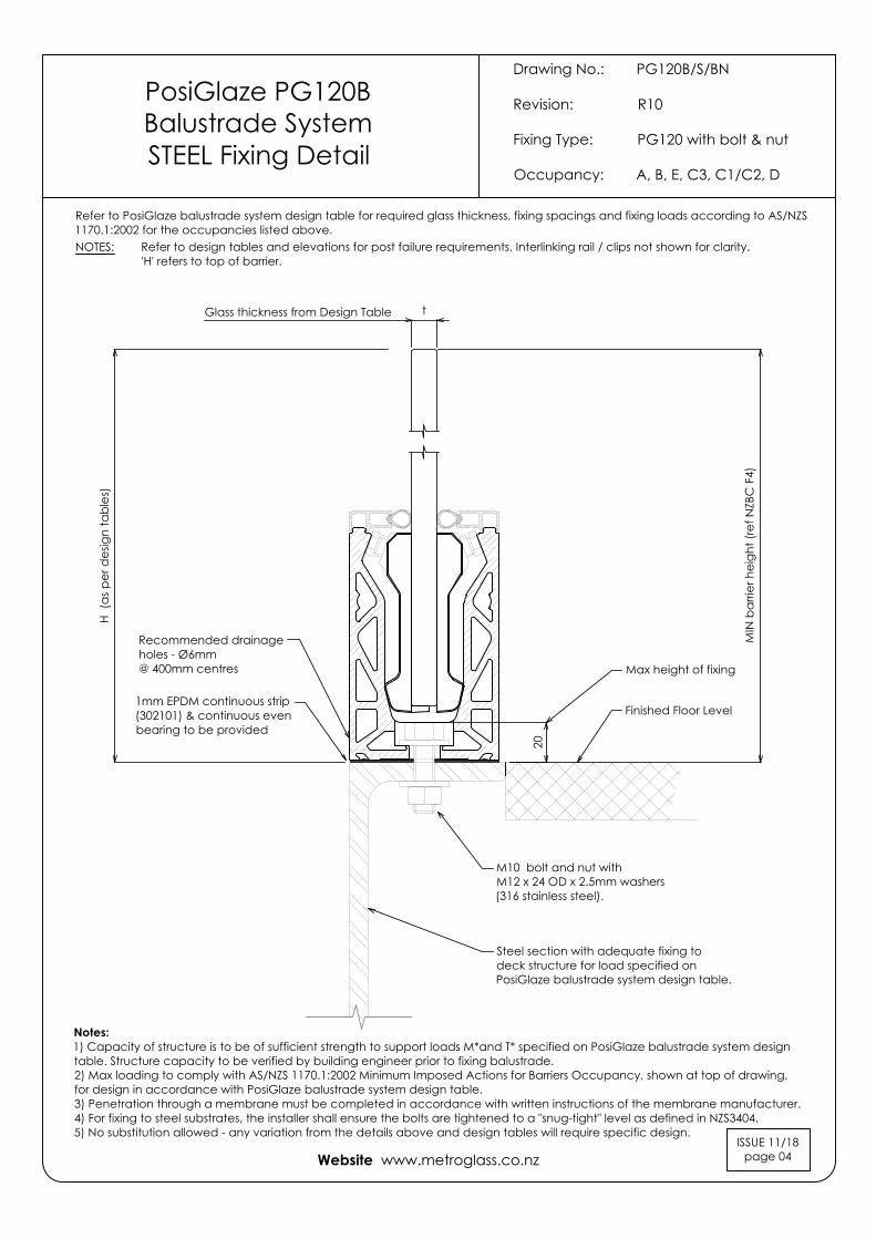
Drawing No.: PG120B/S/BN
Revision: R10
Fixing Type: PG120 with bolt & nut
Occupancy: A, B, E, C3, C1/C2, D
PosiGlaze PG120BBalustrade SystemSTEEL Fixing Detail
Website www.metroglass.co.nz
M10 bolt and nut withM12 x 24 OD x 2.5mm washers(316 stainless steel).
Steel section with adequate fixing todeck structure for load specified onPosiGlaze balustrade system design table.
H (a
s per
des
ign
tabl
es)
Glass thickness from Design Table t
MIN
bar
rier h
eigh
t (re
f NZB
C F
4)
Recommended drainageholes - Ø6mm@ 400mm centres
Finished Floor Level
20
Max height of fixing
Refer to PosiGlaze balustrade system design table for required glass thickness, fixing spacings and fixing loads according to AS/NZS1170.1:2002 for the occupancies listed above.
1mm EPDM continuous strip(302101) & continuous evenbearing to be provided
Notes:1) Capacity of structure is to be of sufficient strength to support loads M*and T* specified on PosiGlaze balustrade system designtable. Structure capacity to be verified by building engineer prior to fixing balustrade.2) Max loading to comply with AS/NZS 1170.1:2002 Minimum Imposed Actions for Barriers Occupancy, shown at top of drawing,for design in accordance with PosiGlaze balustrade system design table.3) Penetration through a membrane must be completed in accordance with written instructions of the membrane manufacturer.4) For fixing to steel substrates, the installer shall ensure the bolts are tightened to a "snug-tight" level as defined in NZS3404.5) No substitution allowed - any variation from the details above and design tables will require specific design.
ISSUE 11/18page 04
NOTES: Refer to design tables and elevations for post failure requirements. Interlinking rail / clips not shown for clarity.'H' refers to top of barrier.

Drawing No.: PG120S-180S/C/RA(M10)
Revision: R10
Fixing Type: PG120S & PG180S with rod anchor (M10)Occupancy: A, B, E, C3, C1/C2, D
PosiGlaze PG120S & PG180SBalustrade System
CONCRETE Fixing Detail
Website www.metroglass.co.nz
H (a
s per
des
ign
tabl
es)
63m
m M
IN
Glass thickness from Design Table t
Concrete building structure to be designed by building engineer tosupport loads as specified on PosiGlaze balustrade system design table.Minimum 25MPa uncracked concrete, 200mm Min thickness.
MIN
bar
rier h
eigh
t (re
f NZB
C F
4)
Structural Slab Level
slab
edge
dist
ance
PG180S
PG 120S shown above
1mm EPDM continuous strip (302100) andcontinuous even bearing to be provided
Recommended drainageholes - Ø6mm@ 400mm centres
M12 x 24 OD x 2.5mm316 grade SS washer
20MAX protrusionof fixing
Refer to PosiGlaze balustrade system design table for required glass thickness, fixing spacings and fixing loads according to AS/NZS1170.1:2002 for the occupancies listed above.
Finished Floor Level
Notes:1) Capacity of structure is to be of sufficient strength to support loads M*and T* specified on PosiGlaze balustrade system designtable. Structure capacity to be verified by building engineer prior to fixing balustrade.2) Max loading to comply with AS/NZS 1170.1:2002 Minimum Imposed Actions for Barriers Occupancy, shown at top of drawing,for design in accordance with PosiGlaze balustrade system design table.3) Penetration through a membrane must be completed in accordance with written instructions of the membrane manufacturer.4) No substitution allowed - any variation from the details above and design tables will require specific design.
ISSUE 11/18page 05
NOTES: Refer to design tables and elevations for post failure requirements.Interlinking rail / clips not shown for clarity.'H' refers to top of barrier.
200m
m M
IN th
ickn
ess (
MIN
25M
Pa u
ncra
cked
con
cret
e)
Hilti HIT-HY 200 + HIT-V-R M10 Grade 316 stainless steel anchor with 160mm embedment into uncracked concrete. Anchors to be installed in accordance with Hilti requirements. For anchors adjacent to corners, first anchor to be placed 120mm from edge of concrete.
NOTE: not suitable for fixing to blockwork. Specific Engineering Design required.
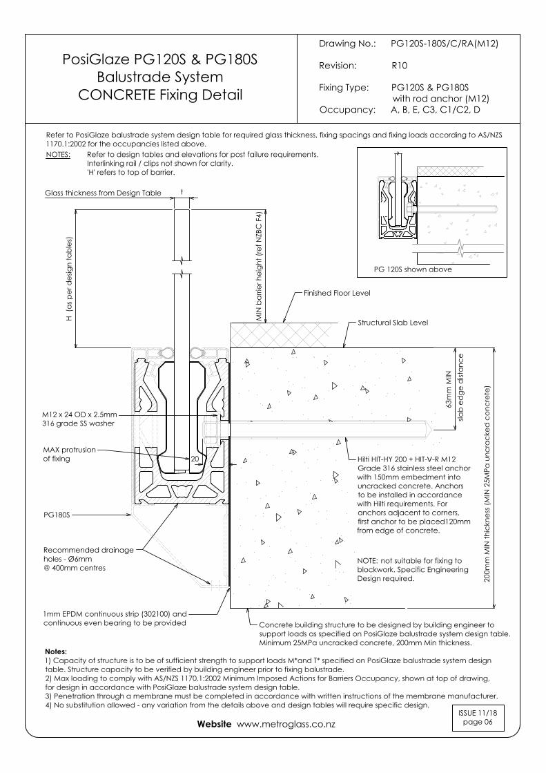
Drawing No.: PG120S-180S/C/RA(M12)
Revision: R10
Fixing Type: PG120S & PG180S with rod anchor (M12)Occupancy: A, B, E, C3, C1/C2, D
PosiGlaze PG120S & PG180SBalustrade System
CONCRETE Fixing Detail
Website www.metroglass.co.nz
H (a
s per
des
ign
tabl
es)
63m
m M
IN
Glass thickness from Design Table t
Concrete building structure to be designed by building engineer tosupport loads as specified on PosiGlaze balustrade system design table.Minimum 25MPa uncracked concrete, 200mm Min thickness.
MIN
bar
rier h
eigh
t (re
f NZB
C F
4)
Structural Slab Level
slab
edge
dist
ance
PG180S
PG 120S shown above
1mm EPDM continuous strip (302100) andcontinuous even bearing to be provided
Recommended drainageholes - Ø6mm@ 400mm centres
M12 x 24 OD x 2.5mm316 grade SS washer
20MAX protrusionof fixing
Refer to PosiGlaze balustrade system design table for required glass thickness, fixing spacings and fixing loads according to AS/NZS1170.1:2002 for the occupancies listed above.
Finished Floor Level
Notes:1) Capacity of structure is to be of sufficient strength to support loads M*and T* specified on PosiGlaze balustrade system designtable. Structure capacity to be verified by building engineer prior to fixing balustrade.2) Max loading to comply with AS/NZS 1170.1:2002 Minimum Imposed Actions for Barriers Occupancy, shown at top of drawing,for design in accordance with PosiGlaze balustrade system design table.3) Penetration through a membrane must be completed in accordance with written instructions of the membrane manufacturer.4) No substitution allowed - any variation from the details above and design tables will require specific design.
ISSUE 11/18page 06
NOTES: Refer to design tables and elevations for post failure requirements.Interlinking rail / clips not shown for clarity.'H' refers to top of barrier.
200m
m M
IN th
ickn
ess (
MIN
25M
Pa u
ncra
cked
con
cret
e)
Hilti HIT-HY 200 + HIT-V-R M12 Grade 316 stainless steel anchor with 150mm embedment into uncracked concrete. Anchors to be installed in accordance with Hilti requirements. For anchors adjacent to corners, first anchor to be placed 120mm from edge of concrete.
NOTE: not suitable for fixing to blockwork. Specific Engineering Design required.

Drawing No.: PG120S-180S/S/BN
Revision: R10
Fixing Type: PG120S & PG180S with bolt and nutOccupancy: A, B, E, C3, C1/C2, D
Website www.metroglass.co.nz
H (a
s per
des
ign
tabl
es)
Glass thickness from Design Table t
MIN
bar
rier h
eigh
t (re
f NZB
C F
4)
PosiGlaze PG120S & PG180SBalustrade SystemSTEEL Fixing Detail
M10 bolt and nut withM12 x 24 OD x 2.5mm washers(316 stainless steel).
Steel section with adequate fixing to deckstructure for load specified on PosiGlazebalustrade system design table.
Finished Floor Level
MIN
52m
m
M12 x 24 OD x 2.5mm316 grade SS washer
20MAX protrusionof fixing
Refer to PosiGlaze balustrade system design table for required glass thickness, fixing spacings and fixing loads according to AS/NZS1170.1:2002 for the occupancies listed above.
Recommended drainageholes - Ø6mm@ 400mm centres
Notes:1) Capacity of structure is to be of sufficient strength to support loads M*and T* specified on PosiGlaze balustrade system designtable. Structure capacity to be verified by building engineer prior to fixing balustrade.2) Max loading to comply with AS/NZS 1170.1:2002 Minimum Imposed Actions for Barriers Occupancy, shown at top of drawing,for design in accordance with PosiGlaze balustrade system design table.3) Penetration through a membrane must be completed in accordance with written instructions of the membrane manufacturer.4) For fixing to steel substrates, the installer shall ensure the bolts are tightened to a "snug-tight" level as defined in NZS3404.5) No substitution allowed - any variation from the details above and design tables will require specific design.
ISSUE 11/18page 07
NOTES: Refer to design tables and elevations for post failure requirements.Interlinking rail / clips not shown for clarity.'H' refers to top of barrier.
PG180S
PG 120S shown above
1mm EPDM continuous strip (302100) andcontinuous even bearing to be provided

Drawing No.: PG120S-180S/T/BN
Revision: R10
Fixing Type: PG120S & PG180S with bolt and nutOccupancy: A, B, E, C3
Website www.metroglass.co.nz
PosiGlaze PG120S & PG180SBalustrade SystemTIMBER Fixing Detail
NOTES:1) Capacity of structure is to be of sufficient strength to support loads M*and T* specified on PosiGlaze balustrade system designtable. Structure capacity to be verified by building engineer where applicable or checked to NZS3604 requirements prior to fixingbalustrade.2) Timber decks designed to NZS 3604:2011 guidelines will meet loading requirement, except for decks including cantilever floorjoists where specific design is required.3) Max loading to comply with AS/NZS 1170.1:2002 Minimum Imposed Actions for Barriers Occupancy, shown at top of drawing,for design in accordance with PosiGlaze balustrade system design table.4) Penetration through a membrane must be completed in accordance with written instructions of the membrane manufacturer.5) For fixing to timber substrates, the installer shall ensure that the bolt / coach screw is sufficiently tightened to reduce movementof the bolt head and washer. Care should be taken not to over tighten the fixings that would cause crushing of the timber orcompromise the thread leading to anchor pull-out.6) No substitution allowed - any variation from the details above and design tables will require specific design.
Glass thickness from Design Table t
MIN
bar
rier h
eigh
t (re
f NZB
C F
4)
H (a
s per
des
ign
tabl
es)
Finished Floor Level
M10 bolt (316 stainless steel)
M10 nut (316 stainless steel)
M12 x 50 square x 5.0mm316 grade SS washer(302098)
M12 x 24 OD x 2.5mm316 grade SS washer
Timber boundary joists (min SG8timber) with adequate fixing todeck structure for loads asspecified on PosiGlaze balustradesystem design table (refer note 2)
MIN
52m
m20
MAX protrusionof fixing
Refer to PosiGlaze balustrade system design table for required glass thickness, fixing spacings and fixing loads according to AS/NZS1170.1:2002 for the occupancies listed above.
Recommended drainageholes - Ø6mm@ 400mm centres
ISSUE 11/18page 08
NOTES: Refer to design tables and elevations for post failure requirements.Interlinking rail / clips not shown for clarity.'H' refers to top of barrier.
PG180S
PG 120S shown above
NOT SUITABLE FOR OCCUPANCY C1/C2, D OR C5
1mm EPDM continuous strip (302100) andcontinuous even bearing to be provided
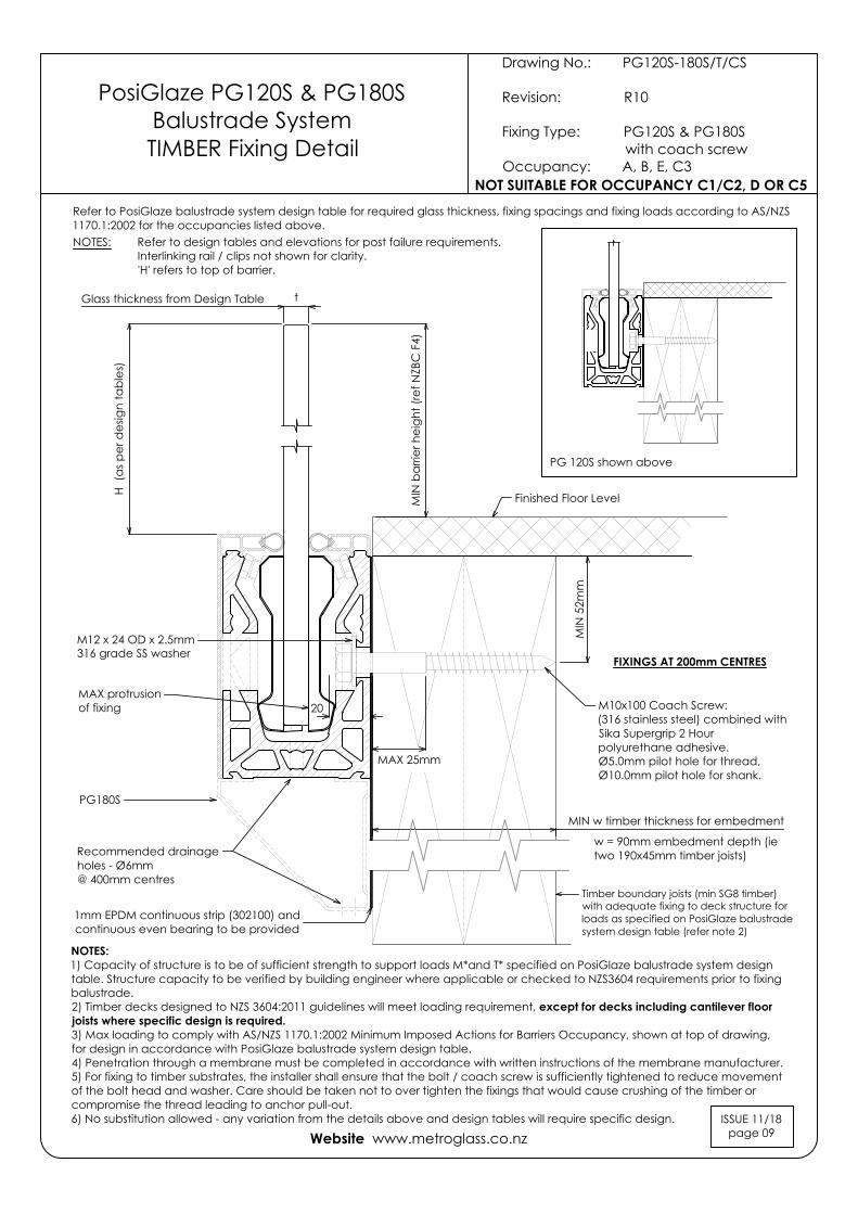
Drawing No.: PG120S-180S/T/CS
Revision: R10
Fixing Type: PG120S & PG180S with coach screwOccupancy: A, B, E, C3
Website www.metroglass.co.nz
Glass thickness from Design Table t
MIN
bar
rier h
eigh
t (re
f NZB
C F
4)
H (a
s per
des
ign
tabl
es)
Finished Floor Level
PG 120S shown above
M12 x 24 OD x 2.5mm316 grade SS washer
PosiGlaze PG120S & PG180SBalustrade SystemTIMBER Fixing Detail
M10x100 Coach Screw:(316 stainless steel) combined withSika Supergrip 2 Hourpolyurethane adhesive.Ø5.0mm pilot hole for thread,Ø10.0mm pilot hole for shank.
FIXINGS AT 200mm CENTRES
MIN
52m
m
MIN w timber thickness for embedment
w = 90mm embedment depth (ietwo 190x45mm timber joists)
Timber boundary joists (min SG8 timber)with adequate fixing to deck structure forloads as specified on PosiGlaze balustradesystem design table (refer note 2)
20MAX protrusionof fixing
Refer to PosiGlaze balustrade system design table for required glass thickness, fixing spacings and fixing loads according to AS/NZS1170.1:2002 for the occupancies listed above.
Recommended drainageholes - Ø6mm@ 400mm centres
NOTES:1) Capacity of structure is to be of sufficient strength to support loads M*and T* specified on PosiGlaze balustrade system designtable. Structure capacity to be verified by building engineer where applicable or checked to NZS3604 requirements prior to fixingbalustrade.2) Timber decks designed to NZS 3604:2011 guidelines will meet loading requirement, except for decks including cantilever floorjoists where specific design is required.3) Max loading to comply with AS/NZS 1170.1:2002 Minimum Imposed Actions for Barriers Occupancy, shown at top of drawing,for design in accordance with PosiGlaze balustrade system design table.4) Penetration through a membrane must be completed in accordance with written instructions of the membrane manufacturer.5) For fixing to timber substrates, the installer shall ensure that the bolt / coach screw is sufficiently tightened to reduce movementof the bolt head and washer. Care should be taken not to over tighten the fixings that would cause crushing of the timber orcompromise the thread leading to anchor pull-out.6) No substitution allowed - any variation from the details above and design tables will require specific design. ISSUE 11/18
page 09
NOTES: Refer to design tables and elevations for post failure requirements.Interlinking rail / clips not shown for clarity.'H' refers to top of barrier.
PG180S
1mm EPDM continuous strip (302100) andcontinuous even bearing to be provided
MAX 25mm
NOT SUITABLE FOR OCCUPANCY C1/C2, D OR C5

POSIGLAZE ELEVATION (DRAWING 01)
ISSUE 11/18page 10
SAFELITE STF GLASS
Residential & CommercialOccupancy types A, A other, C3, B and E.
GLASS & FIXING SPECIFICATIONS:Refer to design table for maximum glass height,maximum fixing spacing and design loads to structure.
POSIGLAZE SYSTEMSAFELITE STF 13.52mm
POSIGLAZE SYSTEMSAFELITE STF 17.52mmSAFELITE STF 21.52mm
MINIMUM PANEL WIDTH1700mm
REFE
R TO
DES
IGN
TA
BLE
FOR
HEIG
HT R
EQUI
REM
ENTS
125mm MAXoverhang at ends
250mm MAXclamp spacing
Panel gap:MIN 14mmMAX 20mm
PANEL WIDTHS < 1700mm REQUIREBALUSTRADE STIFFENER BRACKETS ORINTERLINKING RAIL (Edgetec or S40)
MINIMUM PANEL WIDTH1100mm
REFE
R TO
DES
IGN
TA
BLE
FOR
HEIG
HT R
EQUI
REM
ENTS
125mm MAXoverhang at ends
250mm MAXclamp spacing
Panel gap:MIN 14mmMAX 20mm
STIF
FEN
ER B
RAC
KET
MA
X 20
0mm
FRO
M T
OP
17.52mm - Residential & CommercialOccupancy types A, A other, C3, B and E.
21.52mm - CommercialOccupancy types C1, C2 and D.
IMPORTANT NOTE: The substructure to which the balustrade is to be attached must be designed by a structural engineer to resist the relevant balustrade actions as per B1/VM1.
FOR OCCUPANCIES A, A other, C3, B & E ONLY:PANEL WIDTHS < 1100mm REQUIRE BALUSTRADE STIFFENERBRACKETS OR INTERLINKING RAIL (Edgetec or S40).
FOR OCCUPANCIES C1, C2 & D:1100mm MINIMUM WIDTH APPLIES.
PANEL WIDTH NOTES:Balustrade stiffener brackets or interlinking rail requiredfor panels <1700mm.Minimum panel width where two or more panels are ina straight line = 1000mm.Minimum width for short return panel = 200mm.
PANEL WIDTH NOTES:Balustrade stiffener brackets or interlinking rail requiredfor panels <1100mm.Minimum panel width where two or more panels are ina straight line = 1000mm.Minimum width for short return panel = 200mm.
GLASS & FIXING SPECIFICATIONS:Refer to design table for maximum glass height,maximum fixing spacing and design loads to structure.
R
R
Website www.metroglass.co.nz
FULL HEIGHT SILICONE BUTT JOIN REQUIRED AT CORNER
STIF
FEN
ER B
RAC
KET
MA
X 20
0mm
FRO
M T
OP
FULL HEIGHT SILICONE BUTT JOIN REQUIRED AT CORNER
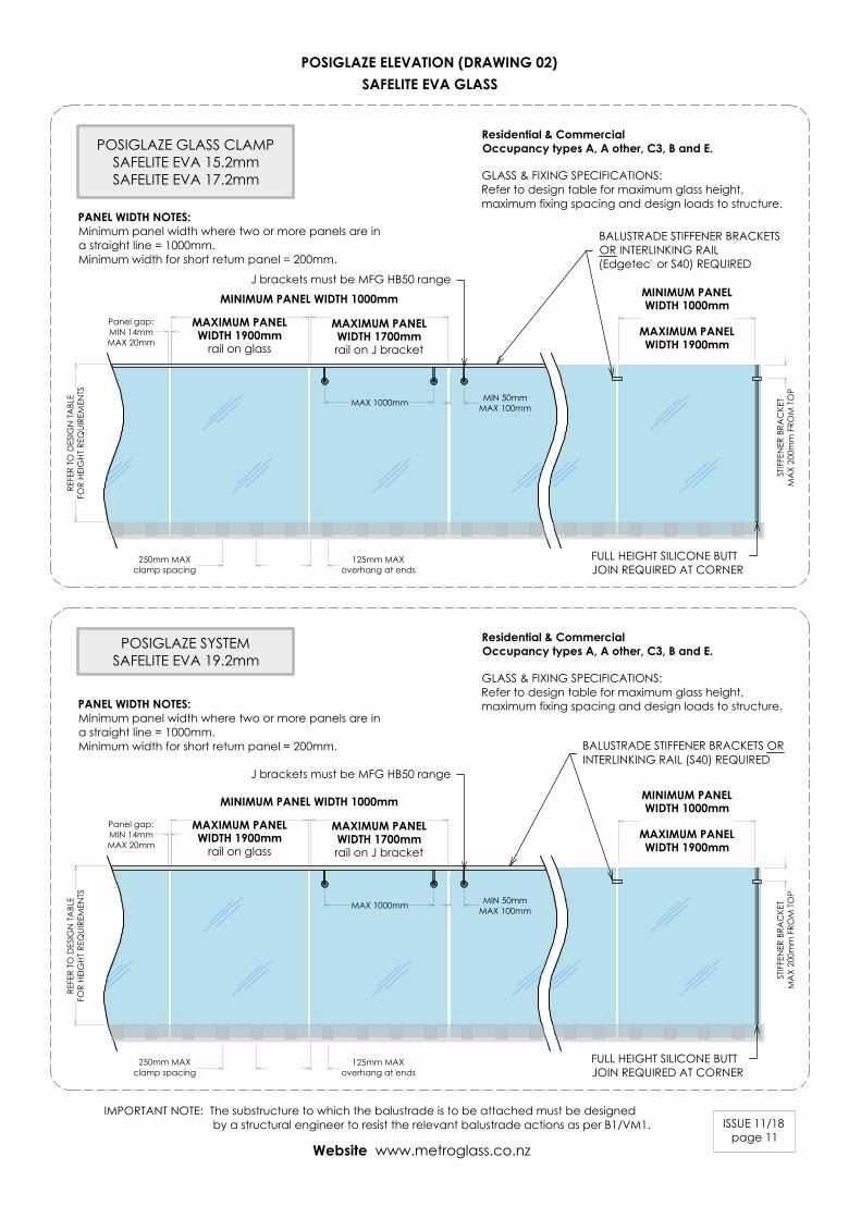
POSIGLAZE ELEVATION (DRAWING 02)
ISSUE 11/18page 11
SAFELITE EVA GLASS
Residential & CommercialOccupancy types A, A other, C3, B and E.
MAXIMUM PANELWIDTH 1900mm
rail on glass
REFE
R TO
DES
IGN
TA
BLE
FOR
HEIG
HT R
EQUI
REM
ENTS
250mm MAXclamp spacing
Panel gap:MIN 14mmMAX 20mm
POSIGLAZE SYSTEMSAFELITE EVA 19.2mm
Residential & CommercialOccupancy types A, A other, C3, B and E.
IMPORTANT NOTE: The substructure to which the balustrade is to be attached must be designed by a structural engineer to resist the relevant balustrade actions as per B1/VM1.
GLASS & FIXING SPECIFICATIONS:Refer to design table for maximum glass height,maximum fixing spacing and design loads to structure.
PANEL WIDTH NOTES:Minimum panel width where two or more panels are ina straight line = 1000mm.Minimum width for short return panel = 200mm.
GLASS & FIXING SPECIFICATIONS:Refer to design table for maximum glass height,maximum fixing spacing and design loads to structure.PANEL WIDTH NOTES:
Minimum panel width where two or more panels are ina straight line = 1000mm.Minimum width for short return panel = 200mm.
Website www.metroglass.co.nz
POSIGLAZE GLASS CLAMPSAFELITE EVA 15.2mmSAFELITE EVA 17.2mm
125mm MAXoverhang at ends
STIF
FEN
ER B
RAC
KET
MA
X 20
0mm
FRO
M T
OP
MINIMUM PANELWIDTH 1000mm
MAXIMUM PANELWIDTH 1900mm
FULL HEIGHT SILICONE BUTTJOIN REQUIRED AT CORNER
BALUSTRADE STIFFENER BRACKETSOR INTERLINKING RAIL(Edgetec or S40) REQUIREDR
MAXIMUM PANELWIDTH 1700mmrail on J bracket
MINIMUM PANEL WIDTH 1000mm
MIN 50mmMAX 100mmMAX 1000mm
MAXIMUM PANELWIDTH 1900mm
rail on glass
REFE
R TO
DES
IGN
TA
BLE
FOR
HEIG
HT R
EQUI
REM
ENTS
250mm MAXclamp spacing
Panel gap:MIN 14mmMAX 20mm
125mm MAXoverhang at ends
STIF
FEN
ER B
RAC
KET
MA
X 20
0mm
FRO
M T
OP
MINIMUM PANELWIDTH 1000mm
MAXIMUM PANELWIDTH 1900mm
FULL HEIGHT SILICONE BUTTJOIN REQUIRED AT CORNER
BALUSTRADE STIFFENER BRACKETS ORINTERLINKING RAIL (S40) REQUIRED
MAXIMUM PANELWIDTH 1700mmrail on J bracket
MINIMUM PANEL WIDTH 1000mm
MIN 50mmMAX 100mmMAX 1000mm
J brackets must be MFG HB50 range
J brackets must be MFG HB50 range

POSIGLAZE ELEVATION (DRAWING 03)
ISSUE 11/18page 12
TEMPAFLOAT GLASS
POSIGLAZE SYSTEMTEMPAFLOAT 12mm
POSIGLAZE SYSTEMTEMPAFLOAT 15mm
REFE
R TO
DES
IGN
TA
BLE
FOR
HEIG
HT R
EQUI
REM
ENTS
125mm MAXoverhang at ends
250mm MAXclamp spacing
Panel gap:MIN 14mmMAX 20mm
Residential & CommercialOccupancy types A, A other, C3, B and E.
Residential & CommercialOccupancy types A, A other, C3, B and E.
IMPORTANT NOTE: The substructure to which the balustrade is to be attached must be designed by a structural engineer to resist the relevant balustrade actions as per B1/VM1.
GLASS & FIXING SPECIFICATIONS:Refer to design table for maximum glass height,maximum fixing spacing and design loads to structure.PANEL WIDTH NOTES:
Minimum panel width where two or more panels are ina straight line = 1000mm.Minimum width for short return panel = 200mm.
GLASS & FIXING SPECIFICATIONS:Refer to design table for maximum glass height,maximum fixing spacing and design loads to structure.PANEL WIDTH NOTES:
Minimum panel width where two or more panels are ina straight line = 1000mm.Minimum width for short return panel = 200mm.
Website www.metroglass.co.nz
INTERLINKING RAIL (S40 or Edgetec ) REQUIRED
MINIMUM PANELWIDTH 1000mm
MAXIMUM PANELWIDTH 1900mm
rail on glass
R
MINIMUM PANELWIDTH 1000mm
MAXIMUM PANELWIDTH 1700mmrail on J bracket
MIN 50mmMAX 100mmMAX 1000mm
REFE
R TO
DES
IGN
TA
BLE
FOR
HEIG
HT R
EQUI
REM
ENTS
125mm MAXoverhang at ends
250mm MAXclamp spacing
Panel gap:MIN 14mmMAX 20mm
INTERLINKING RAIL REQUIRED:S25 (on glass only, MAX 1700mm panels)S40 & Edgetec (on MFG HB50 J brackets, MAX 1700mm panels)S40 & Edgetec (on glass, MAX 1900mm panels)
MINIMUM PANELWIDTH 1000mm
MAXIMUM PANELWIDTH 1900mm
rail on glass
R
MINIMUM PANELWIDTH 1000mm
MAXIMUM PANELWIDTH 1700mmrail on J bracket
MIN 50mmMAX 100mmMAX 1000mm
R
J brackets must beMFG HB50 range
J brackets must beMFG HB50 range

POSIGLAZE ELEVATION (DRAWING 04)
ISSUE 11/18page 13
POOL FENCE
MINIMUM PANELWIDTH 1000mm
1200
mm
abo
ve F
L
125mm MAXoverhang at ends
250mm MAXclamp spacing
Panel gap:MIN 14mmMAX 20mm
NO RAIL REQUIRED
APPLIES TO FREE STANDING POOL FENCES NOTPROTECTING A FALL OF > 1000mm.
As of Jan 2017, complies with Building Codeclause F9 & section 162C of the building Act.
IMPORTANT NOTE: The substructure to which the balustrade is to be attached must be designed by a structural engineer to resist the relevant balustrade actions as per B1/VM1.
GLASS & FIXING SPECIFICATIONS:Refer to design table for maximum glass height,maximum fixing spacing and design loads to structure.
1200
mm
abo
ve F
L
125mm MAXoverhang at ends
250mm MAXclamp spacing
Panel gap:MIN 14mmMAX 20mm
NO RAIL REQUIREDMINIMUM PANELWIDTH 1000mm
POSIGLAZE SYSTEMPOOL FENCE ONLY
(BASE FIX)
GLASS & FIXING SPECIFICATIONS:Refer to design table for maximum glass height,maximum fixing spacing and design loads to structure.
POSIGLAZE SYSTEMPOOL FENCE ONLY
(SIDE FIX)
FFL
FFL
Website www.metroglass.co.nz
APPLIES TO FREE STANDING POOL FENCES NOTPROTECTING A FALL OF > 1000mm.
As of Jan 2017, complies with Building Codeclause F9 & section 162C of the building Act.
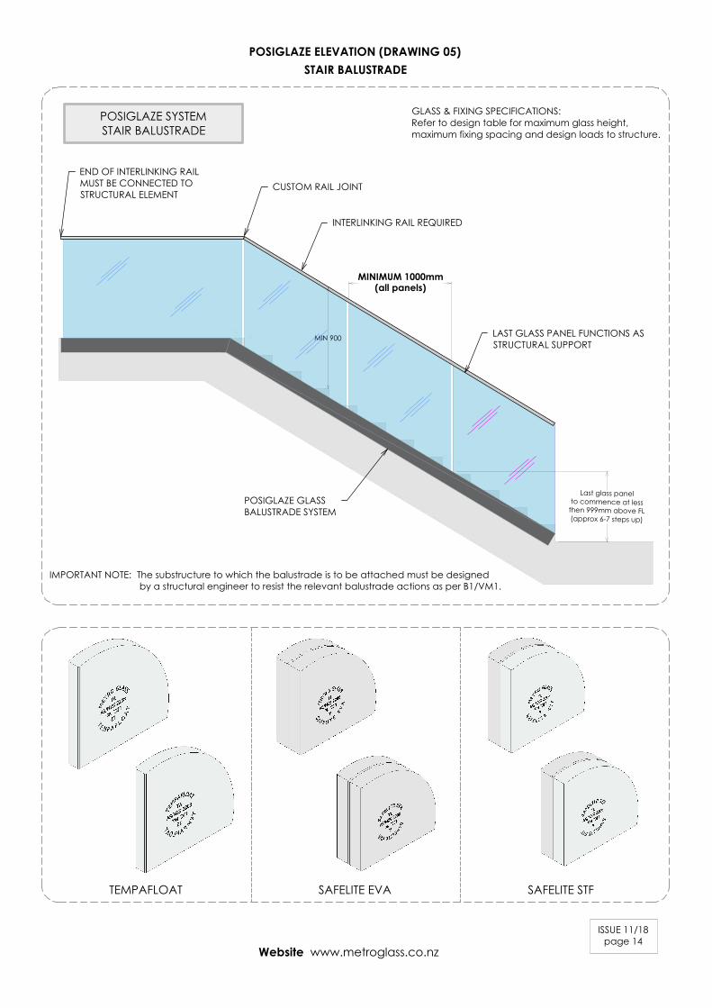
POSIGLAZE ELEVATION (DRAWING 05)
ISSUE 11/18page 14
STAIR BALUSTRADE
POSIGLAZE SYSTEMSTAIR BALUSTRADE
INTERLINKING RAIL REQUIRED
END OF INTERLINKING RAILMUST BE CONNECTED TOSTRUCTURAL ELEMENT
CUSTOM RAIL JOINT
LAST GLASS PANEL FUNCTIONS ASSTRUCTURAL SUPPORT
POSIGLAZE GLASSBALUSTRADE SYSTEM
MIN 900
Last glass panelto commence at less
then 999mm above FL(approx 6-7 steps up)
GLASS & FIXING SPECIFICATIONS:Refer to design table for maximum glass height,maximum fixing spacing and design loads to structure.
IMPORTANT NOTE: The substructure to which the balustrade is to be attached must be designed by a structural engineer to resist the relevant balustrade actions as per B1/VM1.
Website www.metroglass.co.nz
SAFELITE EVATEMPAFLOAT SAFELITE STF
MINIMUM 1000mm(all panels)

POSIGLAZE RAIL & BRACKETS (DRAWING 06)
ISSUE 11/18page 15
BALUSTRADE STIFFENER BRACKETS
Product Code Description
300151
(90° bracket)
Suit glass from 13.5 - 15.5mm.
Stiffener bracket - No holes required.
90° glass to glass.
75mm x 50mm x 25mm.
Duplex 2205. Stainless Steel
Satin finish.
300149
(180° bracket)
Suit glass from 13.5 - 15.5mm.
Stiffener bracket - No holes required.
180° glass to glass.
70mm overall x 25mm.
Duplex 2205. Stainless Steel
Satin finish.
300152
(90° bracket)
Suit glass from 17.52 - 21.52mm.
Stiffener bracket - No holes required.
90° glass to glass.
88mm x 55mm x 25mm.
Duplex 2205. Stainless Steel
Satin finish.
300150
(180° bracket)
Suit glass from 17.52 - 21.52mm.
Stiffener bracket - No holes required.
180° glass to glass.
103mm overall x 25mm.
Duplex 2205. Stainless Steel
Satin finish.
Product Code Description
All brackets are supplied with a selection of gaskets to suit glass thickness and includes stainless steel clamping plates.
13.5-15.5mm GLASS - CORNER BRACKET300151
13.5-15.5mm GLASS - STRAIGHT BRACKET300149
17.52 - 21.52mm GLASS - CORNER BRACKET300152
17.52 - 21.52mm GLASS - STRAIGHT BRACKET300150
Min 12Max 17
Min 14Max 20
Min 14Max 20
Website www.metroglass.co.nz
300153
(wall bracket)
Suit glass from 13.5 - 15.5mm.
Stiffener bracket - No holes required.
90° glass to wall.
65mm x 55mm x 25mm.
Duplex 2205. Stainless Steel
Satin finish.
300154
(wall bracket)
Suit glass from 17.52 - 21.52mm.
Stiffener bracket - No holes required.
90° glass to wall.
65mm x 55mm x 25mm.
Duplex 2205. Stainless Steel
Satin finish.
13.5-15.5mm GLASS - WALL BRACKET300153
17.52 - 21.52mm GLASS - WALL BRACKET300154
Min 11Max 16
Min 11Max 16
Min 12Max 17
Min11Max 16 Min11
Max 16
FULL HEIGHT FULL WIDTH SILICON(DC795 or DC121) BUTT JOIN REQUIRED FOR ALL CORNERS . PREPARE FOR & APPLY STRUCTURAL SILICONE IN ACCORDANCE WITH DOWSIL PREPARATION AND INSTALLATION INSTRUCTIONS.
FULL HEIGHT FULL WIDTH SILICON(DC795 or DC121) BUTT JOIN REQUIRED FOR ALL CORNERS . PREPARE FOR & APPLY STRUCTURAL SILICONE IN ACCORDANCE WITH DOWSIL PREPARATION AND INSTALLATION INSTRUCTIONS.
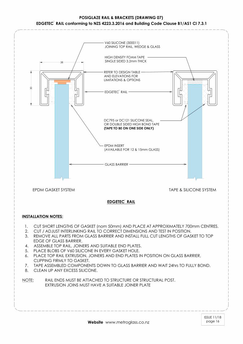
POSIGLAZE RAIL & BRACKETS (DRAWING 07)
ISSUE 11/18page 16
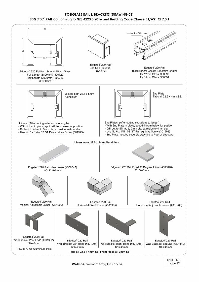
EDGETEC RAIL conforming to NZS 4223.3.2016 and Building Code Clause B1/AS1 Cl 7.3.1
INSTALLATION NOTES:
1. CUT SHORT LENGTHS OF GASKET (nom 50mm) AND PLACE AT APPROXIMATELY 700mm CENTRES.2. CUT / ADJUST INTERLINKING RAIL TO CORRECT DIMENSIONS AND TEST IN POSITION.3. REMOVE ALL PARTS FROM GLASS BARRIER AND INSTALL FULL CUT LENGTHS OF GASKET TO TOP
EDGE OF GLASS BARRIER.4. ASSEMBLE TOP RAIL, JOINERS AND SUITABLE END PLATES.5. PLACE BLOBS OF V60 SILICONE IN EVERY GASKET HOLE.6. PLACE TOP RAIL EXTRUSION, JOINERS AND END PLATES IN POSITION ON GLASS BARRIER,
CLIPPING FIRMLY TO GASKET.7. TAPE ASSEMBLED COMPONENTS DOWN TO GLASS BARRIER AND WAIT 24hrs TO FULLY BOND.8. CLEAN UP ANY EXCESS SILICONE.
NOTE: RAIL ENDS MUST BE ATTACHED TO STRUCTURE OR STRUCTURAL POST.EXTRUSION JOINS MUST HAVE A SUITABLE JOINER PLATE
V60 SILICONE (300011)JOINING TOP RAIL, WEDGE & GLASS
R
Website www.metroglass.co.nz
EDGETEC RAIL
GLASS BARRIER
EPDM GASKET SYSTEM TAPE & SILICONE SYSTEM
EDGETEC RAIL
REFER TO DESIGN TABLEAND ELEVATIONS FORLIMITATIONS & OPTIONS
R
R
38
30
HIGH DENSITY FOAM TAPESINGLE SIDED 3.2mm THICK
EPDM INSERT(AVAILABLE FOR 12 & 15mm GLASS)
DC795 or DC121 SILICONE SEAL,OR DOUBLE SIDED HIGH BOND TAPE(TAPE TO BE ON ONE SIDE ONLY)
ISSUE 11/18page 17
Holes for Silicone
Joiners both 22.5 x 5mm
Aluminium
End Plate
Tabs all 22.5 x 4mm SS.
Joiners: (After cutting extrusions to length)
- With Joiner in place, spot drill from below for position
- Drill out to joiner to 3mm dia, extrusion to 4mm dia
- Use No 6 x 1/4in SS ST Pan sq drive Screw (301993)
End Plates: (After cutting extrusions to length)
- With End Plate in place, spot drill from below for position
- Drill out to SS tab to 3mm dia, extrusion to 4mm dia
- Use No 6 x 1/4in SS ST Pan sq drive Screw (301993)
- End Plate must be securely attached to Post or structure.
Joiners nom. 22.5 x 5mm Aluminium
Tabs all 22.5 x 4mm SS. Front faces all 3mm SS
POSIGLAZE RAIL & BRACKETS (DRAWING 08)EDGETEC RAIL conforming to NZS 4223.3.2016 and Building Code Clause B1/AS1 Cl 7.3.1
38
30
22.2
22.4
Edgetec 220 Rail Inline Joiner (#300847)
80x22.5x5mm
Edgetec 220 Rail Fixed 90 Degree Joiner (#300848)
50x50x5mm
Edgetec 220 Rail
End Cap (300494)
38x30mm
Edgetec 220 Rail for 12mm & 15mm Glass
Full Length (5800mm) 300729
Half Length (2900mm) 300726
38x30mm
Edgetec 220 Rail
Black EPDM Gasket (2900mm length)
for 12mm Glass 300593
for 15mm Glass 300594
Edgetec 220 Rail
Wall Bracket Post End (#301149)
100x45mm
Edgetec 220 Rail
Wall Bracket Left Hand (#301004)
120x45mm
Edgetec 220 Rail
Wall Bracket Post End* (#301992)
60x46mm
* Suits AP65 Aluminium Post
Edgetec 220 Rail
Wall Bracket Right Hand (#301006)
120x45mm
Edgetec 220 Rail
Vertical Adjustable Joiner (#301990)
Edgetec 220 Rail
Horizontal Adjustable Joiner (#301988)
Edgetec 220 Rail
Horizontal Fixed Joiner (#301985)
R
R
R
R R
R R R
R
R R R
R
Website www.metroglass.co.nz
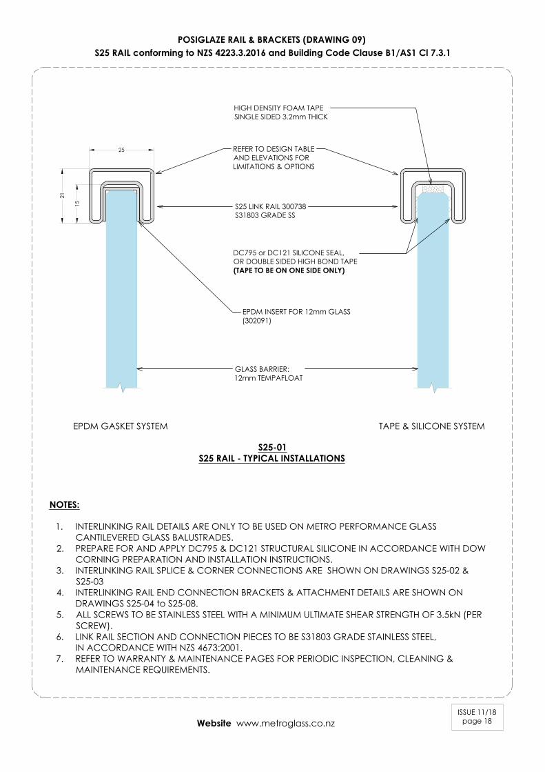
POSIGLAZE RAIL & BRACKETS (DRAWING 09)S25 RAIL conforming to NZS 4223.3.2016 and Building Code Clause B1/AS1 Cl 7.3.1
ISSUE 11/18page 18
S25 LINK RAIL 300738S31803 GRADE SS
DC795 or DC121 SILICONE SEAL,OR DOUBLE SIDED HIGH BOND TAPE(TAPE TO BE ON ONE SIDE ONLY)
HIGH DENSITY FOAM TAPESINGLE SIDED 3.2mm THICK
S25-01S25 RAIL - TYPICAL INSTALLATIONS
NOTES:
1. INTERLINKING RAIL DETAILS ARE ONLY TO BE USED ON METRO PERFORMANCE GLASSCANTILEVERED GLASS BALUSTRADES.
2. PREPARE FOR AND APPLY DC795 & DC121 STRUCTURAL SILICONE IN ACCORDANCE WITH DOWCORNING PREPARATION AND INSTALLATION INSTRUCTIONS.
3. INTERLINKING RAIL SPLICE & CORNER CONNECTIONS ARE SHOWN ON DRAWINGS S25-02 &S25-03
4. INTERLINKING RAIL END CONNECTION BRACKETS & ATTACHMENT DETAILS ARE SHOWN ONDRAWINGS S25-04 to S25-08.
5. ALL SCREWS TO BE STAINLESS STEEL WITH A MINIMUM ULTIMATE SHEAR STRENGTH OF 3.5kN (PERSCREW).
6. LINK RAIL SECTION AND CONNECTION PIECES TO BE S31803 GRADE STAINLESS STEEL,IN ACCORDANCE WITH NZS 4673:2001.
7. REFER TO WARRANTY & MAINTENANCE PAGES FOR PERIODIC INSPECTION, CLEANING &MAINTENANCE REQUIREMENTS.
GLASS BARRIER:12mm TEMPAFLOAT
EPDM INSERT FOR 12mm GLASS(302091)
REFER TO DESIGN TABLEAND ELEVATIONS FORLIMITATIONS & OPTIONS
25
21
15
EPDM GASKET SYSTEM TAPE & SILICONE SYSTEM
Website www.metroglass.co.nz

ISSUE 11/18page 19
POSIGLAZE RAIL & BRACKETS (DRAWING 10)S25 RAIL conforming to NZS 4223.3.2016 and Building Code Clause B1/AS1 Cl 7.3.1
S25-02S25 RAIL - SPLICE CONNECTION DETAIL
S25-03S25 RAIL - 90° CORNER CONNECTION DETAIL
S25 LINK RAIL - SPLICE CONNECTION ELEVATION
SECTION A-A
S25 LINK RAIL SECTION300738
S25 LINK RAILINLINE JOINER
300864
Ø5mm HOLE FORM5 GRUB SCREW
THREADED HOLE FORM5 GRUB SCREW
S25 LINK RAIL300738
S25 LINK RAIL JOINER300864
M5x6mm GRUB SCREWSWITH TUBE LOCK LOCTITE(301978 & 300961)
A
A S25 LINK RAIL JOINER300864
S25 LINK RAIL300738
4 OFF M5 THREADED HOLEFOR GRUB SCREWS
S25 LINK RAIL300738
S25 LINK RAIL300738
S25 LINK RAIL JOINER300864
S25 LINK RAIL300738
4 OFF M5x6 GRUB SCREWSWITH TUBE LOCK LOCTITE(301978 & 300961)
S25 LINK RAIL FIXED 90° CORNER300861
ALL FIXINGS TO BESTAINLESS STEEL
ALL FIXINGS TO BESTAINLESS STEEL
S25 LINK RAIL SECTION300738
Ø5mm HOLE FORM5 GRUB SCREW
M5x6mm GRUB SCREWSWITH TUBE LOCK LOCTITE(301978 & 300961)
S25 LINK RAIL - 90° CORNER CONNECTION ELEVATION
S25 LINK RAIL 90° CORNER300861
B
B
DRILL & TAP 4 OFF M5 THREADEDHOLES FOR GRUB SCREWS
SECTION B-B
S25 LINK RAIL 90° CORNER300861
S25 LINK RAIL 90° CORNER300861
S25 LINK RAIL300738
S25 LINK RAIL300738
Website www.metroglass.co.nz

ISSUE 11/18page 20
POSIGLAZE RAIL & BRACKETS (DRAWING 11)S25 RAIL conforming to NZS 4223.3.2016 and Building Code Clause B1/AS1 Cl 7.3.1
S25-04S25 RAIL WALL BRACKET
S25 LINK RAIL SECTION300738
ALL FIXINGS TO BESTAINLESS STEEL
S25 LINK RAIL300738
S25 LINK RAIL - END BRACKET SECTIONSECTION C-C
S25 LINK RAIL WALL BRACKETRIGHT HAND - 301946LEFT HAND - 300148
c
c
S25 LINK RAIL WALL BRACKET(RIGHT HAND - 301946)
Ø2.5mm PILOT HOLES FOR2 x M5 GRUB SCREWS
ALTERNATIVE GRUBSCREW LOCATIONS
M5x8 GRUB SCREWS(301283)
S25 LINK RAIL300738
S25 LINK RAIL WALL BRACKET
M5x8 GRUB SCREWS(301283)
S25-05S25 RAIL - END BRACKET CONCRETE WALL ATTACHMENT
ALL FIXINGS TO BESTAINLESS STEEL
35mm MINEDGE DISTANCE
S25 LINK RAILWALL BRACKET
2 off 6x70mm HILTI HUS-HR,CR STAINLESS SCREW ANCHORS
100m
m M
INED
GE
DIS
TAN
CE CONCRETE WALL
S25 LINK RAILWALL BRACKET
NOTES:
1. CONCRETE WALL IS TO BEDESIGNED BY PROJECTSTRUCTURAL ENGINEER FOR LOADSIMPOSED BY BALUSTRADE. ULSPOINT LOAD, N* = 0.9KN -INWARDS, OUTWARDS OR DOWN.
2. CONCRETE WALL TO BE MINIMUM140mm THICK.
3. CONCRETE WALL MUST BEREINFORCED & IS TO BE DESIGNED& DETAILED IN ACCORDANCEWITH NZS3101.
4. MINIMUM CONCRETE STRENGTH =20MPa.
RIGHT HAND - 301946
LEFT HAND - 300148
43
47
28
2315
1mm EPDM BETWEENBRACKET AND STRUCTURE(ex 302101)
1mm EPDM BETWEENBRACKET AND STRUCTURE(ex 302101)
Website www.metroglass.co.nz
ISSUE 11/18page 21
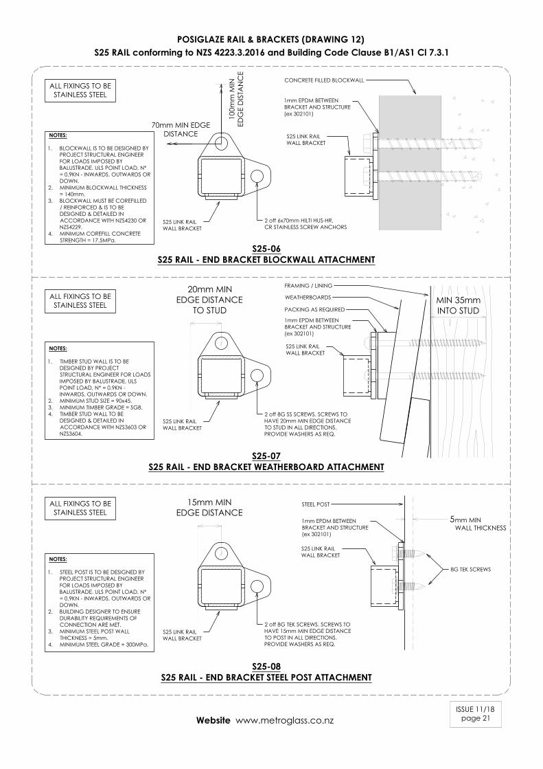
POSIGLAZE RAIL & BRACKETS (DRAWING 12)S25 RAIL conforming to NZS 4223.3.2016 and Building Code Clause B1/AS1 Cl 7.3.1
S25-06S25 RAIL - END BRACKET BLOCKWALL ATTACHMENT
S25-07S25 RAIL - END BRACKET WEATHERBOARD ATTACHMENT
S25-08S25 RAIL - END BRACKET STEEL POST ATTACHMENT
5
STEEL POST
8G TEK SCREWS
S25 LINK RAILWALL BRACKET
2 off 8G TEK SCREWS. SCREWS TOHAVE 15mm MIN EDGE DISTANCETO POST IN ALL DIRECTIONS.PROVIDE WASHERS AS REQ.
2 off 8G SS SCREWS. SCREWS TOHAVE 20mm MIN EDGE DISTANCETO STUD IN ALL DIRECTIONS.PROVIDE WASHERS AS REQ.
S25 LINK RAILWALL BRACKET
MIN 35mmINTO STUD
ALL FIXINGS TO BESTAINLESS STEEL
ALL FIXINGS TO BESTAINLESS STEEL
ALL FIXINGS TO BESTAINLESS STEEL
PACKING AS REQUIRED
WEATHERBOARDS
FRAMING / LINING
2 off 6x70mm HILTI HUS-HR,CR STAINLESS SCREW ANCHORS
100m
m M
INED
GE
DIS
TAN
CE
CONCRETE FILLED BLOCKWALL
S25 LINK RAILWALL BRACKET
70mm MIN EDGEDISTANCE
S25 LINK RAILWALL BRACKET
S25 LINK RAILWALL BRACKET
S25 LINK RAILWALL BRACKET
NOTES:
1. BLOCKWALL IS TO BE DESIGNED BYPROJECT STRUCTURAL ENGINEERFOR LOADS IMPOSED BYBALUSTRADE. ULS POINT LOAD, N*= 0.9KN - INWARDS, OUTWARDS ORDOWN.
2. MINIMUM BLOCKWALL THICKNESS= 140mm.
3. BLOCKWALL MUST BE COREFILLED/ REINFORCED & IS TO BEDESIGNED & DETAILED INACCORDANCE WITH NZS4230 ORNZS4229.
4. MINIMUM COREFILL CONCRETESTRENGTH = 17.5MPa.
NOTES:
1. TIMBER STUD WALL IS TO BEDESIGNED BY PROJECTSTRUCTURAL ENGINEER FOR LOADSIMPOSED BY BALUSTRADE. ULSPOINT LOAD, N* = 0.9KN -INWARDS, OUTWARDS OR DOWN.
2. MINIMUM STUD SIZE = 90x45.3. MINIMUM TIMBER GRADE = SG8.4. TIMBER STUD WALL TO BE
DESIGNED & DETAILED INACCORDANCE WITH NZS3603 ORNZS3604.
NOTES:
1. STEEL POST IS TO BE DESIGNED BYPROJECT STRUCTURAL ENGINEERFOR LOADS IMPOSED BYBALUSTRADE. ULS POINT LOAD, N*= 0.9KN - INWARDS, OUTWARDS ORDOWN.
2. BUILDING DESIGNER TO ENSUREDURABILITY REQUIREMENTS OFCONNECTION ARE MET.
3. MINIMUM STEEL POST WALLTHICKNESS = 5mm.
4. MINIMUM STEEL GRADE = 300MPa.
1mm EPDM BETWEENBRACKET AND STRUCTURE(ex 302101)
1mm EPDM BETWEENBRACKET AND STRUCTURE(ex 302101)
1mm EPDM BETWEENBRACKET AND STRUCTURE(ex 302101)
Website www.metroglass.co.nz
15mm MINEDGE DISTANCE
20mm MINEDGE DISTANCE
TO STUD
mm MINWALL THICKNESS
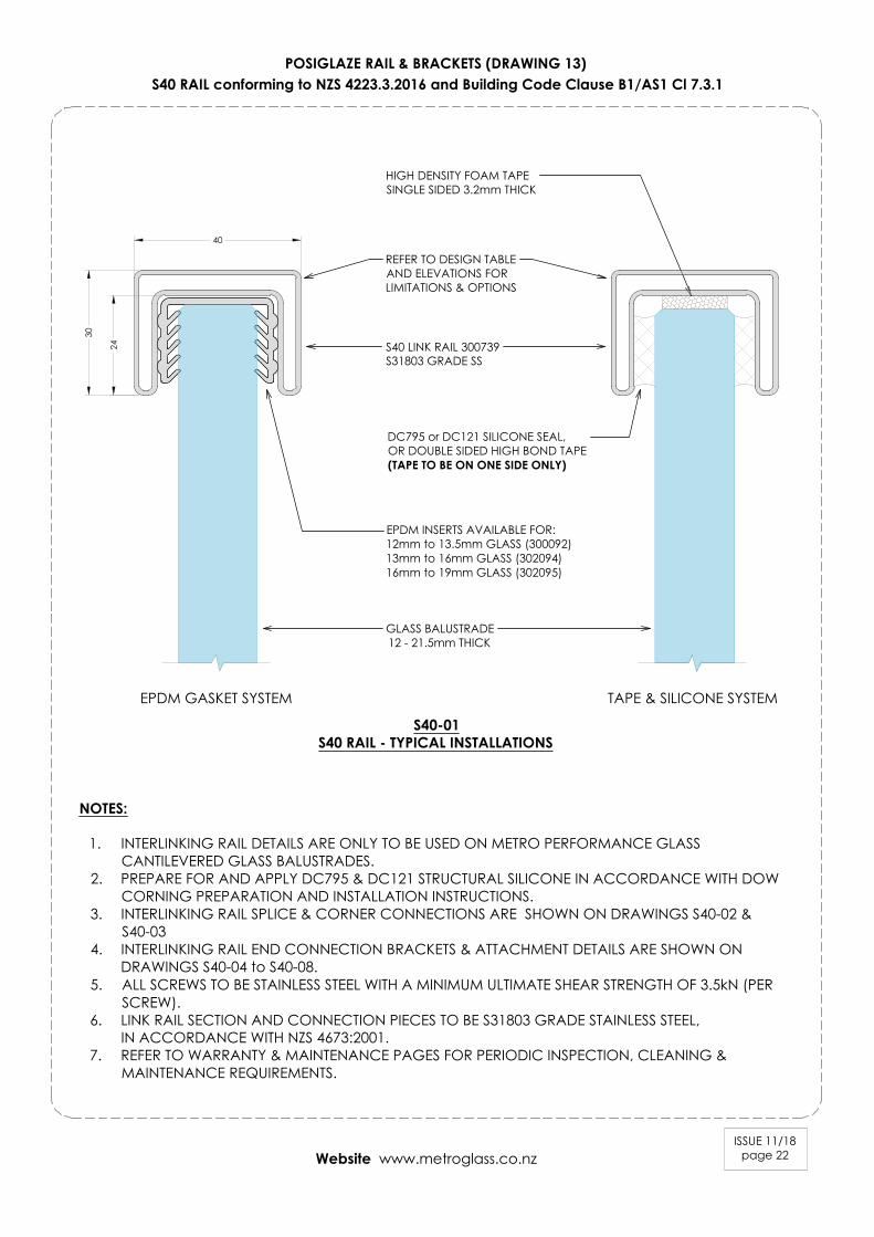
POSIGLAZE RAIL & BRACKETS (DRAWING 13)S40 RAIL conforming to NZS 4223.3.2016 and Building Code Clause B1/AS1 Cl 7.3.1
ISSUE 11/18page 22
S40 LINK RAIL 300739S31803 GRADE SS
DC795 or DC121 SILICONE SEAL,OR DOUBLE SIDED HIGH BOND TAPE(TAPE TO BE ON ONE SIDE ONLY)
EPDM INSERTS AVAILABLE FOR:12mm to 13.5mm GLASS (300092)13mm to 16mm GLASS (302094)16mm to 19mm GLASS (302095)
HIGH DENSITY FOAM TAPESINGLE SIDED 3.2mm THICK
S40-01S40 RAIL - TYPICAL INSTALLATIONS
NOTES:
1. INTERLINKING RAIL DETAILS ARE ONLY TO BE USED ON METRO PERFORMANCE GLASSCANTILEVERED GLASS BALUSTRADES.
2. PREPARE FOR AND APPLY DC795 & DC121 STRUCTURAL SILICONE IN ACCORDANCE WITH DOWCORNING PREPARATION AND INSTALLATION INSTRUCTIONS.
3. INTERLINKING RAIL SPLICE & CORNER CONNECTIONS ARE SHOWN ON DRAWINGS S40-02 &S40-03
4. INTERLINKING RAIL END CONNECTION BRACKETS & ATTACHMENT DETAILS ARE SHOWN ONDRAWINGS S40-04 to S40-08.
5. ALL SCREWS TO BE STAINLESS STEEL WITH A MINIMUM ULTIMATE SHEAR STRENGTH OF 3.5kN (PERSCREW).
6. LINK RAIL SECTION AND CONNECTION PIECES TO BE S31803 GRADE STAINLESS STEEL,IN ACCORDANCE WITH NZS 4673:2001.
7. REFER TO WARRANTY & MAINTENANCE PAGES FOR PERIODIC INSPECTION, CLEANING &MAINTENANCE REQUIREMENTS.
GLASS BALUSTRADE12 - 21.5mm THICK
REFER TO DESIGN TABLEAND ELEVATIONS FORLIMITATIONS & OPTIONS
40
30
24
EPDM GASKET SYSTEM TAPE & SILICONE SYSTEM
Website www.metroglass.co.nz

ISSUE 11/18page 23
POSIGLAZE RAIL & BRACKETS (DRAWING 14)S40 RAIL conforming to NZS 4223.3.2016 and Building Code Clause B1/AS1 Cl 7.3.1
S40-02S40 RAIL - SPLICE CONNECTION DETAIL
S40-03S40 RAIL - 90° CORNER CONNECTION DETAIL
S40 LINK RAIL - SPLICE CONNECTION ELEVATION
SECTION D-D
S40 LINK RAIL SECTION300739
S40 LINK RAILINLINE JOINER
300869
Ø5mm HOLE FORM5 GRUB SCREW
TAP HOLE FORM5 GRUB SCREW
S40 LINK RAIL300739
S40 LINK RAIL JOINER300869
M5x6mm GRUB SCREWSWITH TUBE LOCK LOCTITE(301978 & 300961)
D
D S40 LINK RAIL JOINER300869
S40 LINK RAIL300739
TAP 4 OFF M5 THREADEDHOLE FOR GRUB SCREWS
S40 LINK RAIL300739
S40 LINK RAIL300739
S40 LINK RAIL JOINER300869
S40 LINK RAIL300739
4 OFF M5x6 GRUB SCREWSWITH TUBE LOCK LOCTITE(301978 & 300961)
S40 LINK RAIL FIXED 90° CORNER300866
ALL FIXINGS TO BESTAINLESS STEEL
ALL FIXINGS TO BESTAINLESS STEEL
M5x6mm GRUB SCREWS WITH TUBELOCK LOCTITE (301978 & 300961)
S40 LINK RAIL - 90° CORNER CONNECTION ELEVATION
S40 LINK RAIL 90° CORNER300866
E
E
DRILL & TAP 4 OFF M5 THREADEDHOLES FOR GRUB SCREWS
SECTION E-E
S40 LINK RAIL 90° CORNER300866
S40 LINK RAIL 90° CORNER300866
S40 LINK RAIL300739
S40 LINK RAIL300739
S40 LINK RAIL SECTION300739
Ø5mm HOLE FORM5 GRUB SCREW
Website www.metroglass.co.nz
ISSUE 11/18page 24
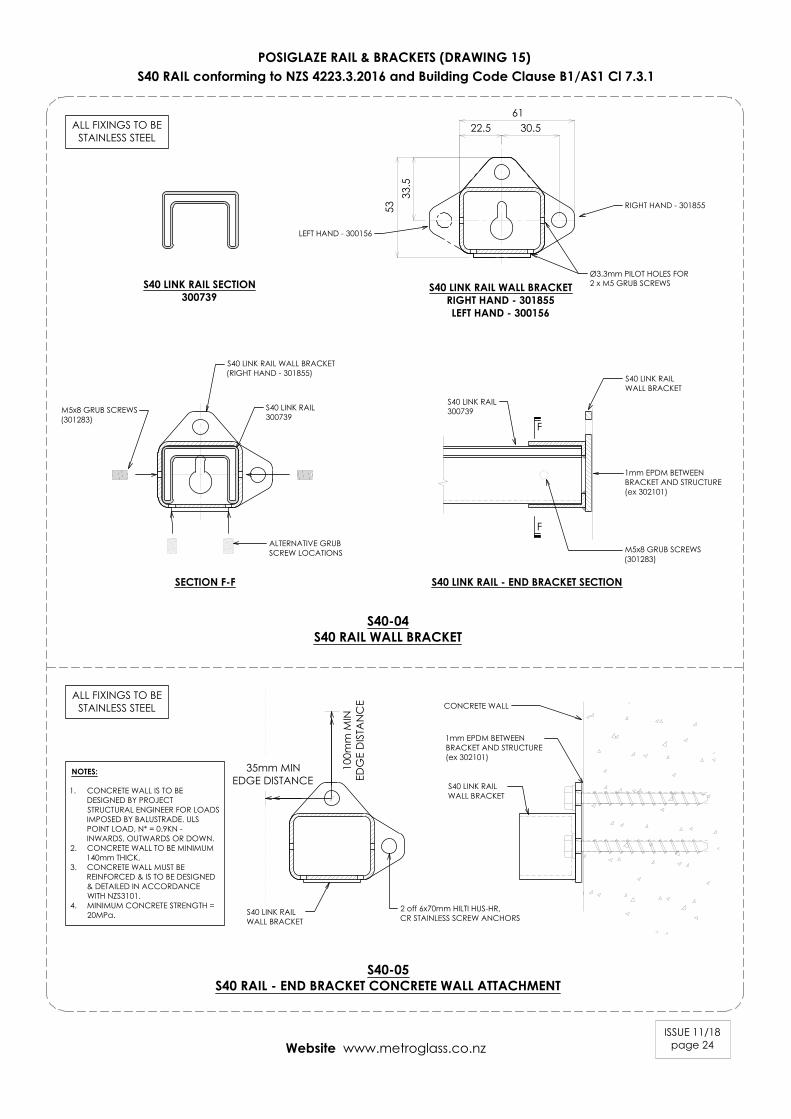
POSIGLAZE RAIL & BRACKETS (DRAWING 15)S40 RAIL conforming to NZS 4223.3.2016 and Building Code Clause B1/AS1 Cl 7.3.1
S40-04S40 RAIL WALL BRACKET
S40 LINK RAIL SECTION300739
ALL FIXINGS TO BESTAINLESS STEEL
S40 LINK RAIL300739
S40 LINK RAIL - END BRACKET SECTIONSECTION F-F
S40 LINK RAIL WALL BRACKETRIGHT HAND - 301855LEFT HAND - 300156
F
F
S40 LINK RAIL WALL BRACKET(RIGHT HAND - 301855)
Ø3.3mm PILOT HOLES FOR2 x M5 GRUB SCREWS
ALTERNATIVE GRUBSCREW LOCATIONS
M5x8 GRUB SCREWS(301283)
S40 LINK RAIL300739
S40 LINK RAILWALL BRACKET
M5x8 GRUB SCREWS(301283)
S40-05S40 RAIL - END BRACKET CONCRETE WALL ATTACHMENT
ALL FIXINGS TO BESTAINLESS STEEL
35mm MINEDGE DISTANCE
S40 LINK RAILWALL BRACKET
2 off 6x70mm HILTI HUS-HR,CR STAINLESS SCREW ANCHORS
100m
m M
INED
GE
DIS
TAN
CE CONCRETE WALL
S40 LINK RAILWALL BRACKET
NOTES:
1. CONCRETE WALL IS TO BEDESIGNED BY PROJECTSTRUCTURAL ENGINEER FOR LOADSIMPOSED BY BALUSTRADE. ULSPOINT LOAD, N* = 0.9KN -INWARDS, OUTWARDS OR DOWN.
2. CONCRETE WALL TO BE MINIMUM140mm THICK.
3. CONCRETE WALL MUST BEREINFORCED & IS TO BE DESIGNED& DETAILED IN ACCORDANCEWITH NZS3101.
4. MINIMUM CONCRETE STRENGTH =20MPa.
RIGHT HAND - 301855
LEFT HAND - 300156
5333
.5
6122.5 30.5
1mm EPDM BETWEENBRACKET AND STRUCTURE(ex 302101)
1mm EPDM BETWEENBRACKET AND STRUCTURE(ex 302101)
Website www.metroglass.co.nz
ISSUE 11/18page 25
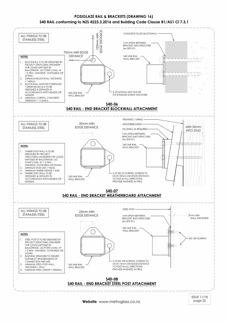
POSIGLAZE RAIL & BRACKETS (DRAWING 16)S40 RAIL conforming to NZS 4223.3.2016 and Building Code Clause B1/AS1 Cl 7.3.1
S40-06S40 RAIL - END BRACKET BLOCKWALL ATTACHMENT
S40-07S40 RAIL - END BRACKET WEATHERBOARD ATTACHMENT
S40-08S40 RAIL - END BRACKET STEEL POST ATTACHMENT
5
STEEL POST
8G TEK SCREWS
S40 LINK RAILWALL BRACKET
2 off 8G TEK SCREWS. SCREWS TOHAVE 15mm MIN EDGE DISTANCETO POST IN ALL DIRECTIONS.PROVIDE WASHERS AS REQ.
2 off 8G SS SCREWS. SCREWS TOHAVE 20mm MIN EDGE DISTANCETO STUD IN ALL DIRECTIONS.PROVIDE WASHERS AS REQ.
S40 LINK RAILWALL BRACKET
MIN 35mmINTO STUD
ALL FIXINGS TO BESTAINLESS STEEL
ALL FIXINGS TO BESTAINLESS STEEL
ALL FIXINGS TO BESTAINLESS STEEL
PACKING AS REQUIRED
WEATHERBOARDS
FRAMING / LINING
2 off 6x70mm HILTI HUS-HR,CR STAINLESS SCREW ANCHORS
100m
m M
INED
GE
DIS
TAN
CE
CONCRETE FILLED BLOCKWALL
S40 LINK RAILWALL BRACKET
70mm MIN EDGEDISTANCE
S40 LINK RAILWALL BRACKET
S40 LINK RAILWALL BRACKET
S40 LINK RAILWALL BRACKET
NOTES:
1. BLOCKWALL IS TO BE DESIGNED BYPROJECT STRUCTURAL ENGINEERFOR LOADS IMPOSED BYBALUSTRADE. ULS POINT LOAD, N*= 0.9KN - INWARDS, OUTWARDS ORDOWN.
2. MINIMUM BLOCKWALL THICKNESS= 140mm.
3. BLOCKWALL MUST BE COREFILLED/ REINFORCED & IS TO BEDESIGNED & DETAILED INACCORDANCE WITH NZS4230 ORNZS4229.
4. MINIMUM COREFILL CONCRETESTRENGTH = 17.5MPa.
NOTES:
1. TIMBER STUD WALL IS TO BEDESIGNED BY PROJECTSTRUCTURAL ENGINEER FOR LOADSIMPOSED BY BALUSTRADE. ULSPOINT LOAD, N* = 0.9KN -INWARDS, OUTWARDS OR DOWN.
2. MINIMUM STUD SIZE = 90x45.3. MINIMUM TIMBER GRADE = SG8.4. TIMBER STUD WALL TO BE
DESIGNED & DETAILED INACCORDANCE WITH NZS3603 ORNZS3604.
NOTES:
1. STEEL POST IS TO BE DESIGNED BYPROJECT STRUCTURAL ENGINEERFOR LOADS IMPOSED BYBALUSTRADE. ULS POINT LOAD, N*= 0.9KN - INWARDS, OUTWARDS ORDOWN.
2. BUILDING DESIGNER TO ENSUREDURABILITY REQUIREMENTS OFCONNECTION ARE MET.
3. MINIMUM STEEL POST WALLTHICKNESS = 5mm.
4. MINIMUM STEEL GRADE = 300MPa.
1mm EPDM BETWEENBRACKET AND STRUCTURE(ex 302101)
1mm EPDM BETWEENBRACKET AND STRUCTURE(ex 302101)
1mm EPDM BETWEENBRACKET AND STRUCTURE(ex 302101)
Website www.metroglass.co.nz
mm MINWALL THICKNESS
23mm MINEDGE DISTANCE
20mm MINEDGE DISTANCE
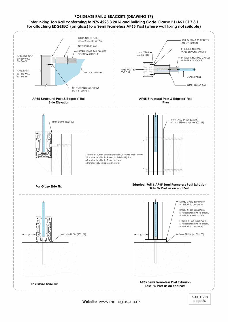
POSIGLAZE RAIL & BRACKETS (DRAWING 17)Interlinking Top Rail conforming to NZS 4223.3.2016 and Building Code Clause B1/AS1 Cl 7.3.1
ISSUE 11/18page 26
For attaching EDGETEC (on glass) to a Semi Frameless AP65 Post (where wall fixing not suitable)
Edgetec Rail & AP65 Semi Frameless Post ExtrusionSide Fix Post as an end PostPosiGlaze Side Fix
AP65 Semi Frameless Post ExtrusionBase Fix Post as an end PostPosiGlaze Base Fix
AP65 Structural Post & Edgetec Rail
Side Elevation
GLASS PANEL
INTERLINKING RAIL GASKETor TAPE & SILICONE
INTERLINKING RAIL
INTERLINKING RAILWALL BRACKET 301992
AP65 TOP CAP301559 MILL301560 SF
SELF TAPPING SS SCREWS8G x 1" 301784
R
Website www.metroglass.co.nz
3mm SPACER (ex 302099)+ 1mm EPDM layer (ex 302101)
AP65 POST301816 MILL301845 SF
AP65 Structural Post & Edgetec Rail
Plan
R
R
INTERLINKING RAIL GASKETor TAPE & SILICONE
INTERLINKING RAIL
SELF TAPPING SS SCREWS8G x 1" 301784
GLASS PANEL
AP65 POST &TOP CAP
145mm for 10mm coachscrews to 2x190x45 joists.95mm for M10 bolts & nuts to 2x140x45 joists.60mm for M10 bolts & nuts to steel.60mm for M10 studs to concrete.
120x80 2 Hole Base Plate:M12 studs to concrete.
120x80 4 Hole Base Plate:M10 coachscrews to timber.M10 bolts & nuts to steel.
110x100 4 Hole Base Plate:M10 coachscrews to timber.M10 studs to concrete
1mm EPDM (ex 302100)1mm EPDM (302101)
1mm EPDM (302100)
1mm EPDM(ex 302101)
INTERLINKING RAILWALL BRACKET 301992
64 67
R
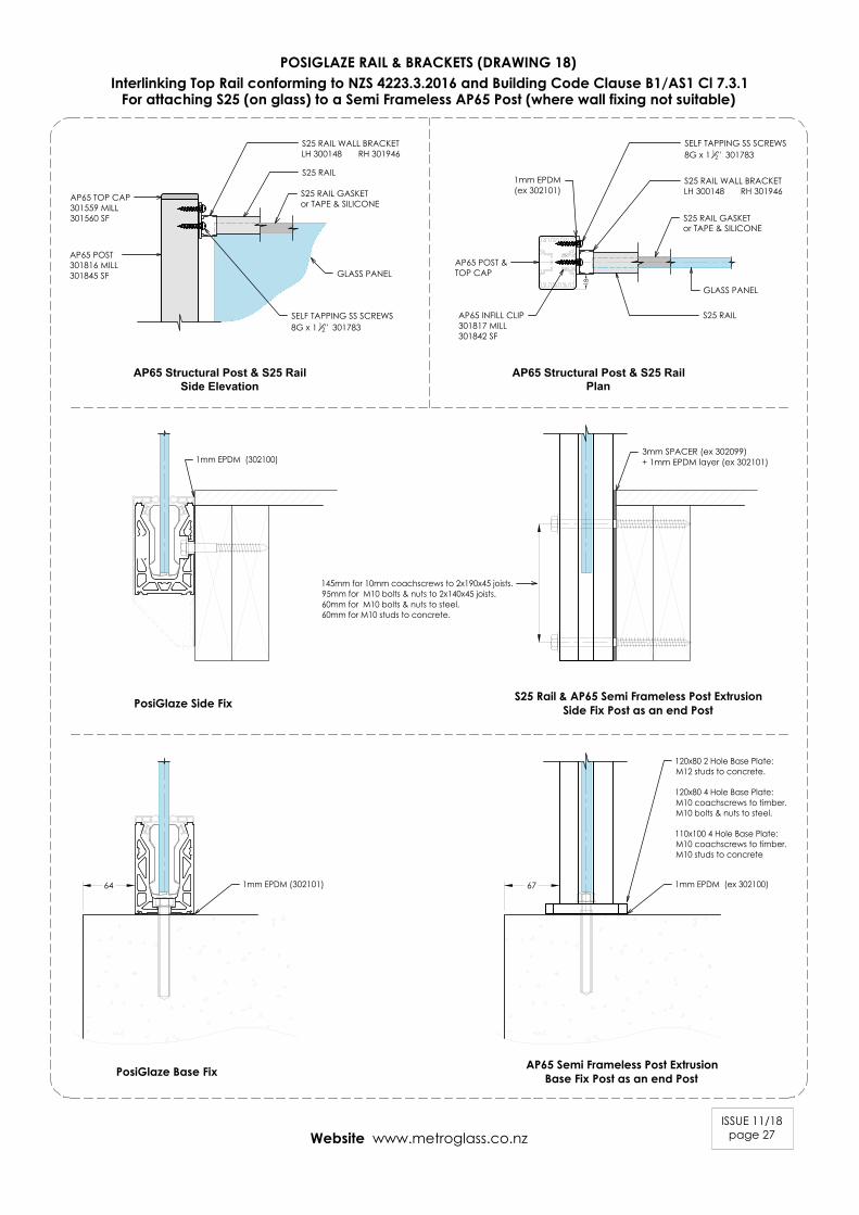
POSIGLAZE RAIL & BRACKETS (DRAWING 18)Interlinking Top Rail conforming to NZS 4223.3.2016 and Building Code Clause B1/AS1 Cl 7.3.1
ISSUE 11/18page 27
For attaching S25 (on glass) to a Semi Frameless AP65 Post (where wall fixing not suitable)
AP65 Structural Post & S25 Rail
Side Elevation
GLASS PANEL
SELF TAPPING SS SCREWS8G x 1 12" 301783
Website www.metroglass.co.nz
AP65 Structural Post & S25 Rail
Plan
S25 Rail & AP65 Semi Frameless Post ExtrusionSide Fix Post as an end PostPosiGlaze Side Fix
AP65 Semi Frameless Post ExtrusionBase Fix Post as an end PostPosiGlaze Base Fix
3mm SPACER (ex 302099)+ 1mm EPDM layer (ex 302101)
145mm for 10mm coachscrews to 2x190x45 joists.95mm for M10 bolts & nuts to 2x140x45 joists.60mm for M10 bolts & nuts to steel.60mm for M10 studs to concrete.
120x80 2 Hole Base Plate:M12 studs to concrete.
120x80 4 Hole Base Plate:M10 coachscrews to timber.M10 bolts & nuts to steel.
110x100 4 Hole Base Plate:M10 coachscrews to timber.M10 studs to concrete
1mm EPDM (ex 302100)1mm EPDM (302101)
1mm EPDM (302100)
S25 RAIL GASKETor TAPE & SILICONE
S25 RAIL
S25 RAIL WALL BRACKETLH 300148 RH 301946
S25 RAIL GASKETor TAPE & SILICONE
S25 RAIL WALL BRACKETLH 300148 RH 301946
SELF TAPPING SS SCREWS8G x 1 12" 301783
GLASS PANEL
AP65 POST &TOP CAP
18
S25 RAIL
64 67
AP65 TOP CAP301559 MILL301560 SF
AP65 POST301816 MILL301845 SF
1mm EPDM(ex 302101)
AP65 INFILL CLIP301817 MILL301842 SF
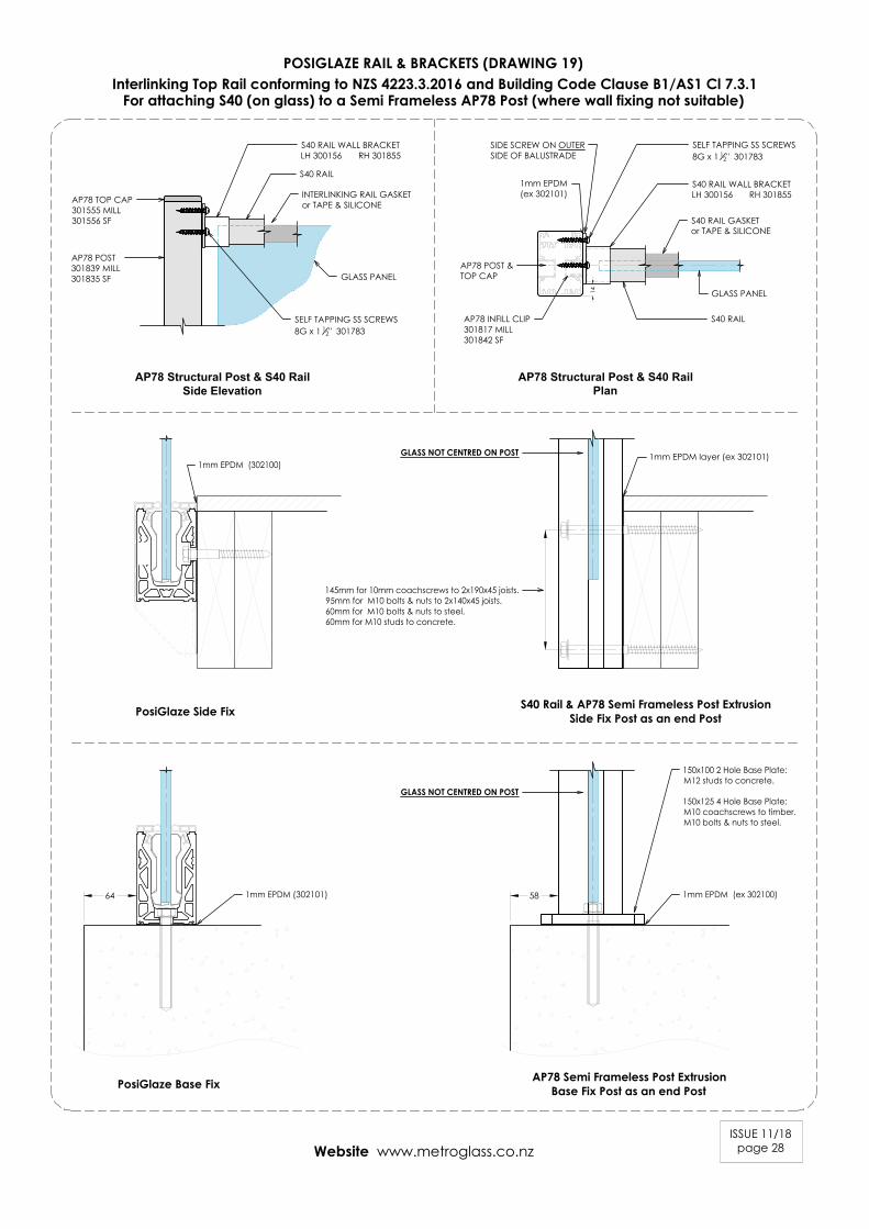
POSIGLAZE RAIL & BRACKETS (DRAWING 19)Interlinking Top Rail conforming to NZS 4223.3.2016 and Building Code Clause B1/AS1 Cl 7.3.1
ISSUE 11/18page 28
For attaching S40 (on glass) to a Semi Frameless AP78 Post (where wall fixing not suitable)
Website www.metroglass.co.nz
AP78 Structural Post & S40 Rail
Side Elevation
AP78 Structural Post & S40 Rail
Plan
GLASS PANEL
INTERLINKING RAIL GASKETor TAPE & SILICONE
S40 RAIL
S40 RAIL WALL BRACKETLH 300156 RH 301855
SELF TAPPING SS SCREWS8G x 1 12" 301783
S40 RAIL GASKETor TAPE & SILICONE
S40 RAIL WALL BRACKETLH 300156 RH 301855
SELF TAPPING SS SCREWS8G x 1 12" 301783
GLASS PANEL
AP78 POST &TOP CAP
14
S40 RAIL
AP78 TOP CAP301555 MILL301556 SF
AP78 POST301839 MILL301835 SF
SIDE SCREW ON OUTERSIDE OF BALUSTRADE
S40 Rail & AP78 Semi Frameless Post ExtrusionSide Fix Post as an end PostPosiGlaze Side Fix
AP78 Semi Frameless Post ExtrusionBase Fix Post as an end PostPosiGlaze Base Fix
1mm EPDM layer (ex 302101)
145mm for 10mm coachscrews to 2x190x45 joists.95mm for M10 bolts & nuts to 2x140x45 joists.60mm for M10 bolts & nuts to steel.60mm for M10 studs to concrete.
150x100 2 Hole Base Plate:M12 studs to concrete.
150x125 4 Hole Base Plate:M10 coachscrews to timber.M10 bolts & nuts to steel.
1mm EPDM (ex 302100)1mm EPDM (302101)
1mm EPDM (302100)GLASS NOT CENTRED ON POST
GLASS NOT CENTRED ON POST
64 58
1mm EPDM(ex 302101)
AP78 INFILL CLIP301817 MILL301842 SF
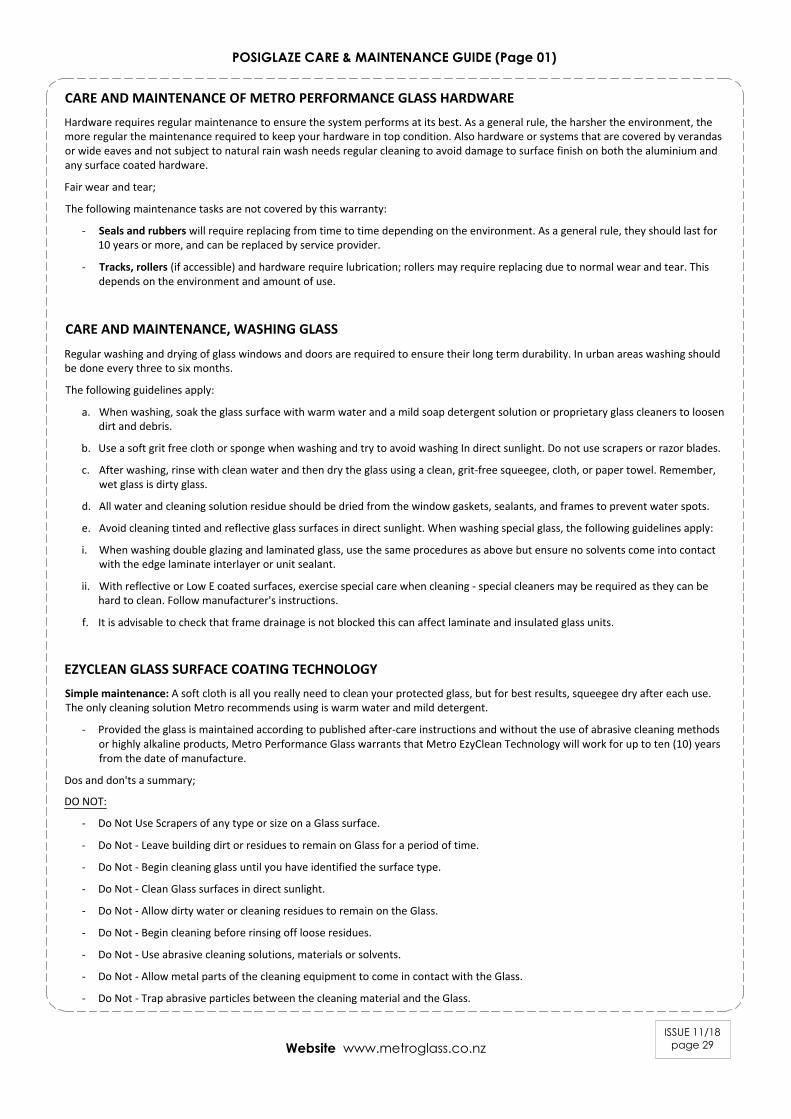
POSIGLAZE CARE & MAINTENANCE GUIDE (Page 01)
ISSUE 11/18page 29Website www.metroglass.co.nz
CARE AND MAINTENANCE OF METRO PERFORMANCE GLASS HARDWAREHardware requires regular maintenance to ensure the system performs at its best. As a general rule, the harsher the environment, themore regular the maintenance required to keep your hardware in top condition. Also hardware or systems that are covered by verandasor wide eaves and not subject to natural rain wash needs regular cleaning to avoid damage to surface finish on both the aluminium andany surface coated hardware.
Fair wear and tear;
The following maintenance tasks are not covered by this warranty:
- Seals and rubbers will require replacing from time to time depending on the environment. As a general rule, they should last for10 years or more, and can be replaced by service provider.
- Tracks, rollers (if accessible) and hardware require lubrication; rollers may require replacing due to normal wear and tear. Thisdepends on the environment and amount of use.
CARE AND MAINTENANCE, WASHING GLASS
Regular washing and drying of glass windows and doors are required to ensure their long term durability. In urban areas washing shouldbe done every three to six months.
The following guidelines apply:
a. When washing, soak the glass surface with warm water and a mild soap detergent solution or proprietary glass cleaners to loosendirt and debris.
b. Use a soft grit free cloth or sponge when washing and try to avoid washing In direct sunlight. Do not use scrapers or razor blades.
c. After washing, rinse with clean water and then dry the glass using a clean, grit-free squeegee, cloth, or paper towel. Remember,wet glass is dirty glass.
d. All water and cleaning solution residue should be dried from the window gaskets, sealants, and frames to prevent water spots.
e. Avoid cleaning tinted and reflective glass surfaces in direct sunlight. When washing special glass, the following guidelines apply:
i. When washing double glazing and laminated glass, use the same procedures as above but ensure no solvents come into contactwith the edge laminate interlayer or unit sealant.
ii. With reflective or Low E coated surfaces, exercise special care when cleaning - special cleaners may be required as they can behard to clean. Follow manufacturer's instructions.
f. It is advisable to check that frame drainage is not blocked this can affect laminate and insulated glass units.
EZYCLEAN GLASS SURFACE COATING TECHNOLOGYSimple maintenance: A soft cloth is all you really need to clean your protected glass, but for best results, squeegee dry after each use.The only cleaning solution Metro recommends using is warm water and mild detergent.
- Provided the glass is maintained according to published after-care instructions and without the use of abrasive cleaning methodsor highly alkaline products, Metro Performance Glass warrants that Metro EzyClean Technology will work for up to ten (10) yearsfrom the date of manufacture.
Dos and don'ts a summary;
DO NOT:
- Do Not Use Scrapers of any type or size on a Glass surface.
- Do Not - Leave building dirt or residues to remain on Glass for a period of time.
- Do Not - Begin cleaning glass until you have identified the surface type.
- Do Not - Clean Glass surfaces in direct sunlight.
- Do Not - Allow dirty water or cleaning residues to remain on the Glass.
- Do Not - Begin cleaning before rinsing off loose residues.
- Do Not - Use abrasive cleaning solutions, materials or solvents.
- Do Not - Allow metal parts of the cleaning equipment to come in contact with the Glass.
- Do Not - Trap abrasive particles between the cleaning material and the Glass.
ISSUE 11/18page 30Website www.metroglass.co.nz
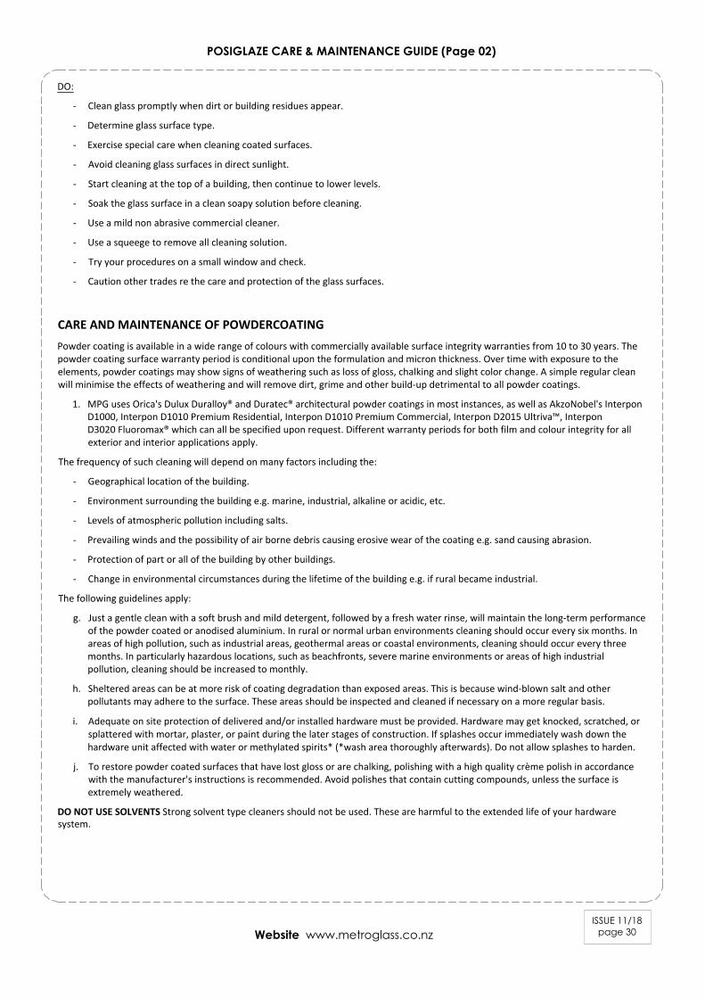
POSIGLAZE CARE & MAINTENANCE GUIDE (Page 02)
DO:
- Clean glass promptly when dirt or building residues appear.
- Determine glass surface type.
- Exercise special care when cleaning coated surfaces.
- Avoid cleaning glass surfaces in direct sunlight.
- Start cleaning at the top of a building, then continue to lower levels.
- Soak the glass surface in a clean soapy solution before cleaning.
- Use a mild non abrasive commercial cleaner.
- Use a squeege to remove all cleaning solution.
- Try your procedures on a small window and check.
- Caution other trades re the care and protection of the glass surfaces.
CARE AND MAINTENANCE OF POWDERCOATINGPowder coating is available in a wide range of colours with commercially available surface integrity warranties from 10 to 30 years. Thepowder coating surface warranty period is conditional upon the formulation and micron thickness. Over time with exposure to theelements, powder coatings may show signs of weathering such as loss of gloss, chalking and slight color change. A simple regular cleanwill minimise the effects of weathering and will remove dirt, grime and other build-up detrimental to all powder coatings.
1. MPG uses Orica's Dulux Duralloy® and Duratec® architectural powder coatings in most instances, as well as AkzoNobel's InterponD1000, Interpon D1010 Premium Residential, Interpon D1010 Premium Commercial, Interpon D2015 Ultriva™, InterponD3020 Fluoromax® which can all be specified upon request. Different warranty periods for both film and colour integrity for allexterior and interior applications apply.
The frequency of such cleaning will depend on many factors including the:
- Geographical location of the building.
- Environment surrounding the building e.g. marine, industrial, alkaline or acidic, etc.
- Levels of atmospheric pollution including salts.
- Prevailing winds and the possibility of air borne debris causing erosive wear of the coating e.g. sand causing abrasion.
- Protection of part or all of the building by other buildings.
- Change in environmental circumstances during the lifetime of the building e.g. if rural became industrial.
The following guidelines apply:
g. Just a gentle clean with a soft brush and mild detergent, followed by a fresh water rinse, will maintain the long-term performanceof the powder coated or anodised aluminium. In rural or normal urban environments cleaning should occur every six months. Inareas of high pollution, such as industrial areas, geothermal areas or coastal environments, cleaning should occur every threemonths. In particularly hazardous locations, such as beachfronts, severe marine environments or areas of high industrialpollution, cleaning should be increased to monthly.
h. Sheltered areas can be at more risk of coating degradation than exposed areas. This is because wind-blown salt and otherpollutants may adhere to the surface. These areas should be inspected and cleaned if necessary on a more regular basis.
i. Adequate on site protection of delivered and/or installed hardware must be provided. Hardware may get knocked, scratched, orsplattered with mortar, plaster, or paint during the later stages of construction. If splashes occur immediately wash down thehardware unit affected with water or methylated spirits* (*wash area thoroughly afterwards). Do not allow splashes to harden.
j. To restore powder coated surfaces that have lost gloss or are chalking, polishing with a high quality crème polish in accordancewith the manufacturer's instructions is recommended. Avoid polishes that contain cutting compounds, unless the surface isextremely weathered.
DO NOT USE SOLVENTS Strong solvent type cleaners should not be used. These are harmful to the extended life of your hardwaresystem.
ISSUE 11/18page 31Website www.metroglass.co.nz
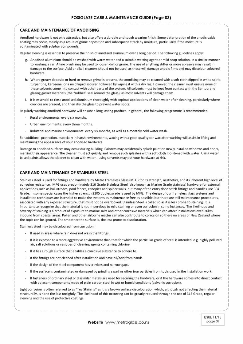
POSIGLAZE CARE & MAINTENANCE GUIDE (Page 03)
CARE AND MAINTENANCE OF ANODISINGAnodised hardware is not only attractive, but also offers a durable and tough wearing finish. Some deterioration of the anodic oxidecoating may occur, mainly as a result of grime deposition and subsequent attack by moisture, particularly if the moisture iscontaminated with sulphur compounds.
Regular cleaning is essential to preserve the finish of anodised aluminium over a long period. The following guidelines apply:
g. Anodised aluminium should be washed with warm water and a suitable wetting agent or mild soap solution, in a similar mannerto washing a car. A fine brush may be used to loosen dirt or grime. The use of anything stiffer or more abrasive may result indamage to the surface. Acid or alkali cleaners should not be used, as these will damage anodic films and may discolour colouredhardware.
h. Where greasy deposits or hard to remove grime is present, the anodising may be cleaned with a soft cloth dipped in white spirit,turpentine, kerosene, or a mild liquid scourer, followed by wiping it with a dry rag. However, the cleaner must ensure none ofthese solvents come into contact with other parts of the system. All solvents must be kept from contact with the Santopreneglazing gasket materials (the “rubber” seal around the glass), as most solvents will damage them.
i. It is essential to rinse anodised aluminium thoroughly with copious applications of clean water after cleaning, particularly wherecrevices are present, and then dry the glass to prevent water spots.
Regularly washing anodised hardware will ensure a long lasting product. In general, the following programme is recommended:
- Rural environments: every six months.
- Urban environments: every three months.
- Industrial and marine environments: every six months, as well as a monthly cold water wash.
For additional protection, especially in harsh environments, waxing with a good quality car wax after washing will assist in lifting andmaintaining the appearance of your anodised hardware.
Damage to anodised surfaces may occur during building. Painters may accidentally splash paint on newly installed windows and doors,marring their appearance. The cleaner must act quickly and remove such splashes with a soft cloth moistened with water. Using waterbased paints allows the cleaner to clean with water - using solvents may put your hardware at risk.
CARE AND MAINTENANCE OF STAINLESS STEELStainless steel is used for fittings and hardware by Metro Frameless Glass (MFG) for its strength, aesthetics, and its inherent high level ofcorrosion resistance. MFG uses predominately 316 Grade Stainless Steel (also known as Marine Grade stainless) hardware for externalapplications such as balustrades, pool fences, canopies and spider walls, but many of the entry door patch fittings and handles use 304Grade. In some special cases the higher strength 2205 duplex grade is used by MFG. The design of our frameless glass systems andinstallation techniques are intended to make the systems as maintenance free as possible, but there are still maintenance procedures,associated with any exposed structure, that must not be overlooked. Stainless Steel is called so as it is less prone to staining. It isimportant to recognize that the material is not impervious to mild staining or even corrosion in some instances. The likelihood andseverity of staining is a product of exposure to marine salts and other corrosive materials which can affect installations even 20kminbound from coastal areas. Pollen and other airborne matter can also contribute to corrosion so there no areas of New Zealand wherethe topic can be ignored. The smoother the surface is, the less prone to discoloration.
Stainless steel may be discoloured from corrosion;
- If used in areas where rain does not wash the fittings.
- If it is exposed to a more aggressive environment than that for which the particular grade of steel is intended, e.g. highly pollutedair, salt solutions or residues of cleaning agents containing chlorine.
- If it has a rough surface that enables a corrosive substance to adhere to.
- If the fittings are not cleaned after installation and have oil/acid from hands.
- If the design of the steel component has crevices and narrow gaps.
- If the surface is contaminated or damaged by grinding swarf or other iron particles from tools used in the installation work.
- If fasteners of ordinary steel or dissimilar metals are used for securing the hardware, or if the hardware comes into direct contactwith adjacent components made of plain carbon steel in wet or humid conditions (galvanic corrosion).
Light corrosion is often referred to as “Tea Staining” as it is a brown surface discolouration which, although not affecting the materialstructurally, is none the less unsightly. The likelihood of this occurring can be greatly reduced through the use of 316 Grade, regularcleaning and the use of protective coatings.
ISSUE 11/18page 32Website www.metroglass.co.nz
POSIGLAZE CARE & MAINTENANCE GUIDE (Page 04)
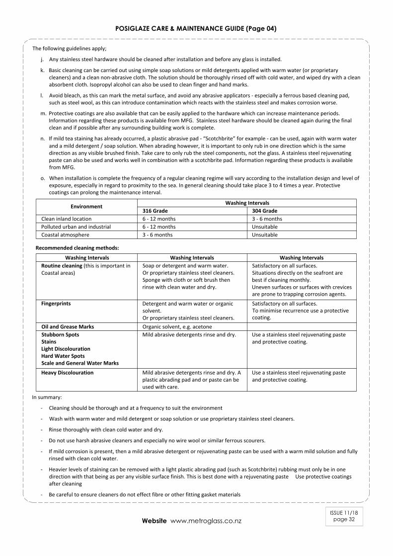
The following guidelines apply;
j. Any stainless steel hardware should be cleaned after installation and before any glass is installed.
k. Basic cleaning can be carried out using simple soap solutions or mild detergents applied with warm water (or proprietarycleaners) and a clean non-abrasive cloth. The solution should be thoroughly rinsed off with cold water, and wiped dry with a cleanabsorbent cloth. Isopropyl alcohol can also be used to clean finger and hand marks.
l. Avoid bleach, as this can mark the metal surface, and avoid any abrasive applicators - especially a ferrous based cleaning pad,such as steel wool, as this can introduce contamination which reacts with the stainless steel and makes corrosion worse.
m. Protective coatings are also available that can be easily applied to the hardware which can increase maintenance periods.Information regarding these products is available from MFG. Stainless steel hardware should be cleaned again during the finalclean and if possible after any surrounding building work is complete.
n. If mild tea staining has already occurred, a plastic abrasive pad - “Scotchbrite” for example - can be used, again with warm waterand a mild detergent / soap solution. When abrading however, it is important to only rub in one direction which is the samedirection as any visible brushed finish. Take care to only rub the steel components, not the glass. A stainless steel rejuvenatingpaste can also be used and works well in combination with a scotchbrite pad. Information regarding these products is availablefrom MFG.
o. When installation is complete the frequency of a regular cleaning regime will vary according to the installation design and level ofexposure, especially in regard to proximity to the sea. In general cleaning should take place 3 to 4 times a year. Protectivecoatings can prolong the maintenance interval.
In summary:
- Cleaning should be thorough and at a frequency to suit the environment
- Wash with warm water and mild detergent or soap solution or use proprietary stainless steel cleaners.
- Rinse thoroughly with clean cold water and dry.
- Do not use harsh abrasive cleaners and especially no wire wool or similar ferrous scourers.
- If mild corrosion is present, then a mild abrasive detergent or rejuvenating paste can be used with a warm mild solution and fullyrinsed with clean cold water.
- Heavier levels of staining can be removed with a light plastic abrading pad (such as Scotchbrite) rubbing must only be in onedirection with that being as per any visible surface finish. This is best done with a rejuvenating paste Use protective coatingsafter cleaning
- Be careful to ensure cleaners do not effect fibre or other fitting gasket materials
Environment Washing Intervals316 Grade 304 Grade6 - 12 months 3 - 6 monthsClean inland location6 - 12 months3 - 6 months
UnsuitableUnsuitable
Polluted urban and industrialCoastal atmosphere
Washing Intervals Washing Intervals Washing IntervalsRoutine cleaning (this is important inCoastal areas)
Soap or detergent and warm water.Or proprietary stainless steel cleaners.Sponge with cloth or soft brush thenrinse with clean water and dry.
Satisfactory on all surfaces.Situations directly on the seafront arebest if cleaning monthly.Uneven surfaces or surfaces with crevicesare prone to trapping corrosion agents.
Recommended cleaning methods:
Fingerprints Detergent and warm water or organicsolvent.Or proprietary stainless steel cleaners.
Satisfactory on all surfaces.To minimise recurrence use a protectivecoating.
Oil and Grease Marks Organic solvent, e.g. acetoneStubborn SpotsStainsLight DiscolourationHard Water SpotsScale and General Water Marks
Mild abrasive detergents rinse and dry. Use a stainless steel rejuvenating pasteand protective coating.
Mild abrasive detergents rinse and dry. Aplastic abrading pad and or paste can beused with care.
Use a stainless steel rejuvenating pasteand protective coating.
Heavy Discolouration
ISSUE 11/18page 33Website www.metroglass.co.nz
POSIGLAZE CARE & MAINTENANCE GUIDE (Page 05)
CARE AND MAINTENANCE OF HANDLES / MECHANISMS
Periodic maintenance of handles / mechanisms is essential, this includes locks, handles, hinges, levers, rollers, bolts, etc. This appliesparticularly to mechanisms with moving parts that require lubrication. Before doing any cleaning or maintenance, you must establishexactly what hardware has been installed and how it has been constructed.
Lubrication for Mechanisms;
Mechanisms include hinges, cylinders, locks, rollers and fasteners. You can keep these mechanisms in good working order throughregular cleaning and lubrication.
p. MPG recommend a Teflon-based lubricate or please refer to the manufacturer's care instructions. A soft bristle brush can be usedon exposed parts. Apply Teflon-based lubricate to the moving parts - you don't need to use very much. This will limit corrosion ofthe exposed metals. MPG advise to do this once every two months. If, however your hardware is near the sea or exposed to saltair, we recommend you lubricate the components once every month.
Electrical Entrance Systems;
Do not let the product get wet.
q. Keep clear of debris and general dirt.
r. Wipe the keypads or swipe the device with a clean damp cloth.
s. Do NOT use solvents.
t. Replacement batteries will be required.
SCRATCHES AND METAL SCRAPERSScratches can occur from hard pointed objects or poor handling, but most often occurs from the careless removal of foreign matter fromthe glass surface. Mortar splatter and paint are common offenders and efforts to remove after hardening almost always lead to surfacedamage.
u. It is essential that the foreign materials are removed before they harden. Better still, if construction work continues after glazing,that the glazed areas are protected by adhesive plastic films or suitable covers.
v. One of the common mistakes made by non-glass trades people, including glass cleaning contractors, is the use of razor blades orother metal scrapers on a large portion of the glass surface. Using large blades to scrape a window clean carries considerable riskof causing damage to the glass.
w. The glass industry, fabricators, distributors and installers neither condones nor recommends any scraping of glass surfaces withmetal blades or knives. Such scraping usually permanently damages or scratches the glass surfaces.
x. When paint or other construction materials cannot be removed with normal cleaning procedures, a new 25mm razor blade mayhave to be used. The razor blade should be used on small spots only. Cleaning should be done in one direction only. Never scrapein a back and forth motion as this could trap particles under the blade that could scratch the glass. Blades or scrapers candislodge “pickup” on toughened and heat strengthened glass. There are fine particles of glass that are fused on to the surfaceduring toughening. Once dislodged they can scratch the glass.
ONSITE CONSTRUCTION / INSTALLATION PROTECTION
Hardware Protection during Installation:
y. All the activity on a construction site means that your hardware items may get knocked or scratched, splattered with mortar,plaster, textured coating or paint during the later stages of construction.
z. Please ensure that all hardware articles are masked or covered at this time. It is far easier to prevent accidents than to try andcorrect them. Should your hardware receive mortar or paint splashes see that these are removed before cure and follow theinstructions outlined above.
For further information, please refer to the PS1 or MPG instructions and guidelines on our websites.