Portalwaschanlage Portal wash unit GENIUS / VARIUS GENIUS / … · 2018. 12. 10. · APKG 10-36V DC...
144
Portalwaschanlage Portal wash unit GENIUS / VARIUS GENIUS / VARIUS C16x C16x GRUNDMODELL BASIC MODEL Ersatzteilliste Spare parts list
Transcript of Portalwaschanlage Portal wash unit GENIUS / VARIUS GENIUS / … · 2018. 12. 10. · APKG 10-36V DC...
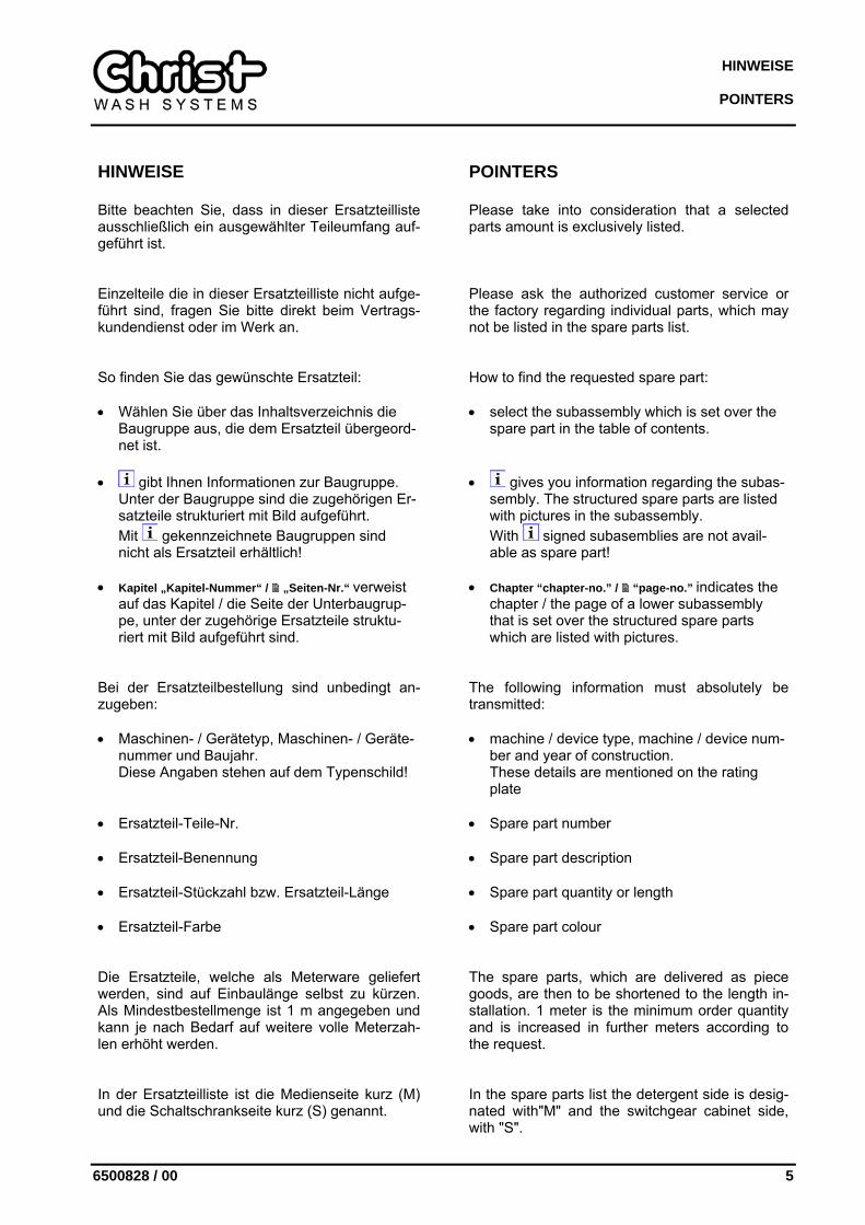
Portalwaschanlage Portal wash unit GENIUS / VARIUS GENIUS / VARIUS C16x C16x
GRUNDMODELL
BASIC MODEL
Ersatzteilliste Spare parts list

Ersatzteilliste Spare parts list Portalwaschanlage Portal wash unit GENIUS / VARIUS GENIUS / VARIUS C16x C16x
GRUNDMODELL BASIC MODEL
Ident.-Nr.: 6500828 Ident-no.: 6500828 Revision: 00 Edition: 00 Stand: 03.07.2007 Date: 03.07.2007
Werk: Otto Christ AG Memminger Str. 51 87734 BENNINGEN
Factory: Otto Christ AG Memminger Str. 51 87734 BENNINGEN DEUTSCHLAND
Telefon: 08331-857-0 Telephone: +49 (0)8331-857-0 Telefax: 08331-857-185 Telefax: +49 (0)8331-857-185
Copyright Kein Teil der Ersatzteilliste darf in irgendeiner Form ohne vorherige schriftliche Zustimmung der Otto Christ AG reproduziert oder unter Verwen-dung elektronischer Systeme verarbeitet, verviel-fältigt oder verbreitet werden. Auch die Überset-zung in eine andere Sprache bedarf der schriftli-chen Genehmigung. Diese Dokumentation ist ausschließlich dem Besitzer der Anlage oder Mit-arbeitern der Otto Christ AG zum persönlichen Gebrauch anvertraut.
Copyright No part of this spare parts list may in any form whatsoever be reproduced without previous writ-ten permission by Otto Christ AG, nor used, cop-ied, or distributed by means of electronic devices. Equally, the translation of this manual in any other language requires written permission. This documentation is exclusively meant to be con-sulted by staff in charge of assembly, manual service and surveillance.
Technische Änderung Die Otto Christ AG behält sich vor, die in dieser Ersatzteilliste enthaltenen Angaben, Ausführun-gen und technischen Daten ohne vorherige An-kündigung zu ändern.
Technical changes Otto Christ AG is entitled to revise descriptions, information and technical data of this spare parts list without previous notice at any time if so re-quired by technical progress.

HINWEISE
POINTERS
6500828 / 00 5
HINWEISE
POINTERS
Bitte beachten Sie, dass in dieser Ersatzteilliste ausschließlich ein ausgewählter Teileumfang auf-geführt ist.
Please take into consideration that a selected parts amount is exclusively listed.
Einzelteile die in dieser Ersatzteilliste nicht aufge-führt sind, fragen Sie bitte direkt beim Vertrags-kundendienst oder im Werk an.
Please ask the authorized customer service or the factory regarding individual parts, which may not be listed in the spare parts list.
So finden Sie das gewünschte Ersatzteil: • Wählen Sie über das Inhaltsverzeichnis die
Baugruppe aus, die dem Ersatzteil übergeord-net ist.
How to find the requested spare part: • select the subassembly which is set over the
spare part in the table of contents.
• gibt Ihnen Informationen zur Baugruppe. Unter der Baugruppe sind die zugehörigen Er-satzteile strukturiert mit Bild aufgeführt. Mit gekennzeichnete Baugruppen sind nicht als Ersatzteil erhältlich!
• Kapitel „Kapitel-Nummer“ / „Seiten-Nr.“ verweist
auf das Kapitel / die Seite der Unterbaugrup-pe, unter der zugehörige Ersatzteile struktu-riert mit Bild aufgeführt sind.
• gives you information regarding the subas-sembly. The structured spare parts are listed with pictures in the subassembly. With signed subasemblies are not avail-able as spare part!
• Chapter “chapter-no.” / “page-no.” indicates the
chapter / the page of a lower subassembly that is set over the structured spare parts which are listed with pictures.
Bei der Ersatzteilbestellung sind unbedingt an-zugeben: • Maschinen- / Gerätetyp, Maschinen- / Geräte-
nummer und Baujahr. Diese Angaben stehen auf dem Typenschild!
The following information must absolutely be transmitted: • machine / device type, machine / device num-
ber and year of construction. These details are mentioned on the rating plate
• Ersatzteil-Teile-Nr.
• Spare part number
• Ersatzteil-Benennung
• Spare part description
• Ersatzteil-Stückzahl bzw. Ersatzteil-Länge
• Spare part quantity or length
• Ersatzteil-Farbe
• Spare part colour
Die Ersatzteile, welche als Meterware geliefert werden, sind auf Einbaulänge selbst zu kürzen. Als Mindestbestellmenge ist 1 m angegeben und kann je nach Bedarf auf weitere volle Meterzah-len erhöht werden.
The spare parts, which are delivered as piece goods, are then to be shortened to the length in-stallation. 1 meter is the minimum order quantity and is increased in further meters according to the request.
In der Ersatzteilliste ist die Medienseite kurz (M) und die Schaltschrankseite kurz (S) genannt.
In the spare parts list the detergent side is desig-nated with"M" and the switchgear cabinet side, with "S".

INHALTSVERZEICHNIS
CONTENTS
6500828 / 00 7
INHALTSVERZEICHNIS / CONTENTS SEITE / PAGE
1 BAUGRUPPENÜBERSICHT SUBASSEMBLY OVERVIEW 11
2 FAHRWERK CHASSIS 13
2.1 Fahrwerk Grundmodell Standard Chassis Basic model standard 14
2.1.1 Fahrantrieb Travelling gear 17
2.2 Fahrwerk Grundmodell Standard mit Wabeg oder 50 mm höher Chassis Basic model standard with shunting platform for vehicle or 50 mm higher 18
2.2.1 Fahrantrieb komplett versenkt Travelling gear counter-sunk complete 21
2.3 Fahrwerk versenkt Standard / 50 mm höher Chassis counter-sunk standard / 50 mm higher 22
3 SEITENWALZENSYSTEM SIDE CYLINDER SYSTEM 25
3.1 Seitenwalzensystem Side cylinder system 27
3.1.1 Laufkatze (S/M) komplett Trolley (S/M) complete 34
3.1.2 Energiekettenführung komplett Energy guide chain complete 37
3.2 Antriebseinheit Drive unit 38
3.2.1 Seitenwalzenantrieb 100 1/min (Sensotex) Side brush drive 100 1/min (Sensotex) 39
3.2.2 Seitenwalzenantrieb 120 1/min (Bürste/Sensofil) Side brush drive 120 1/min (brush/Sensofil) 41
3.3 Seitenwalzenrohr starr Side cylinder tube rigid 43
3.4 Seitenwalzenrohr mit Gelenkeinrichtung Side cylinder tube with articulation 44
3.5 Bürsten-Ausstattung Brush equipment 46
3.6 Sensotex II-Ausstattung Sensotex II equipment 47
3.7 Sensofil I-Ausstattung Sensofil I equipment 49
4 DACHWALZENSYSTEM KOMPLETT ROOF CYLINDER SYSTEM COMPLETE 53
4.1 Dachwalzensystem Roof cylinder system 54
4.1.1 Hubantrieb komplett Lifting device complete 57
INHALTSVERZEICHNIS CONTENTS
8 6500828 / 00
4.2 Walzenantrieb Cylinder drive 59
4.3 Dachwalzenrohr Roof cylinder tube 61
4.4 Bürsten-Ausstattung Brush equipment 62
4.5 Sensotex II-Ausstattung Sensotex II equipment 63
4.6 Sensofil I-Ausstattung Sensofil I equipment 64
5 TROCKNUNGSSYSTEM DRYING SYSTEM 65
5.1 Dachtrocknung Roof drying 66
5.1.1 Elektro-Einbauteile Electric installation parts 70
5.1.2 Laufschlitteneinheit rechts Carriage unit right 73
5.1.3 Laufschlitteneinheit links Carriage unit left 75
5.2 Seitentrocknung Side drying 77
5.3 Hubsystem Dachdüse Lifting device roof nozzle 79
6 VERBLENDUNG FACING 83
6.1 Verblendung C160 Facing C160 84
6.1.1 Frontblende komplett Front panel complete 86
6.1.2 Tür-System komplett Door system complete 87
6.1.3 Fahrwerksverblendung komplett Chassis facing complete 88
6.1.4 Frontverblendung Seitenholm komplett Front facing Side bar complete 89
6.1.5 Heckverblendung Seitenholm komplett Rear facing side bar complete 90
6.2 Verblendung C163 Facing C163 91
6.2.1 Heckverblendung komplett Rear facing complete 93
6.2.2 Frontverblendung Seitenholm komplett Front facing Side bar complete 95
6.2.3 Heckverblendung Seitenholm komplett Rear facing side bar complete 96

INHALTSVERZEICHNIS
CONTENTS
6500828 / 00 9
7 WASSER- UND DOSIERSYSTEM WATER AND DOSING SYSTEM 97
7.1 Wasser- und Dosiersystem C160 Water and dosing system C160 98
7.1.1 Frischwasser-Modul Fresh water module 101
7.1.1.1 Wassermodul Water module 102
7.1.1.2 Wassermodul A-II Water module A-II 105
7.1.2 Seitenwalzen-Bewässerung Side cylinders watering 107
7.1.3 Schlauchbaum Tube harness 108
7.1.4 Seitenwalzenbewässerung unten komplett Side cylinders watering below complete 109
7.1.5 Frontblenden-Bewässerung komplett Frischwasser Front panel watering complete fresh water 111
7.1.6 Dosiersystem Dosing system 114
7.2 Wasser- und Dosiersystem C163 Water and dosing system C163 117
7.2.1 Frontblenden-Bewässerung komplett Frischwasser Front panel watering complete fresh water 120
7.2.2 Bewässerung-Fuss komplett Trocknungshilfe Watering foot complete desiccant 122
7.2.3 Dachwalzen-Bewässerung komplett Frischwasser Roof cylinder watering complete fresh water 123
8 STEUERUNGSSYSTEM CONTROL SYSTEM 125
8.1 Schaltanlage Switchboard plant 126
8.2 Elektro-Einbauteile Electric installation parts 131
9 DRUCKLUFT-GRUNDSYSTEM C16X COMPRESSED AIR BASIC SYSTEM C16X 133
9.1 Luftplatte komplett Air plate complete 135
10 WASSER/LUFT WARTUNGSMODUL WATER/AIR MAINTENACE MODULE 141

1
6500828 / 00 11
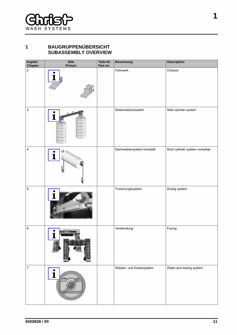
1 BAUGRUPPENÜBERSICHT SUBASSEMBLY OVERVIEW
Kapitel Chapter
Bild Picture
Teile-Nr. Part no
Benennung Description
2
Fahrwerk Chassis
3
Seitenwalzensystem Side cylinder system
4
Dachwalzensystem komplett Roof cylinder system complete
5
Trocknungssystem Drying system
6
Verblendung Facing
7
Wasser- und Dosiersystem Water and dosing system
1
12 6500828 / 00
Kapitel Chapter
Bild Picture
Teile-Nr. Part no
Benennung Description
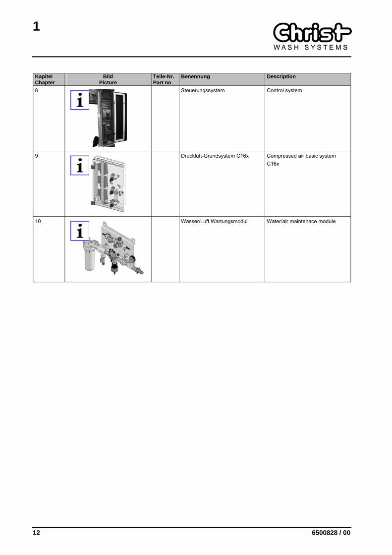
8
Steuerungssystem Control system
9
Druckluft-Grundsystem C16x Compressed air basic system C16x
10
Wasser/Luft Wartungsmodul Water/air maintenace module
2
6500828 / 00 13
2 FAHRWERK CHASSIS
Kapitel Chapter
Bild Picture
Teile-Nr. Part no
Benennung Description
2.1
6100663 Fahrwerk Grundmodell Standard Chassis Basic model standard
2.2
6100683 Fahrwerk Grundmodell Standard mit Wabeg oder 50 mm höher
Chassis Basic model standard with shunting platform for vehicle or 50 mm higher
2.3
6100673 Fahrwerk versenkt Standard Chassis counter-sunk standard
2.3
6100684 Fahrwerk versenkt 50 mm höher Chassis counter-sunk 50 mm higher
2
14 6500828 / 00
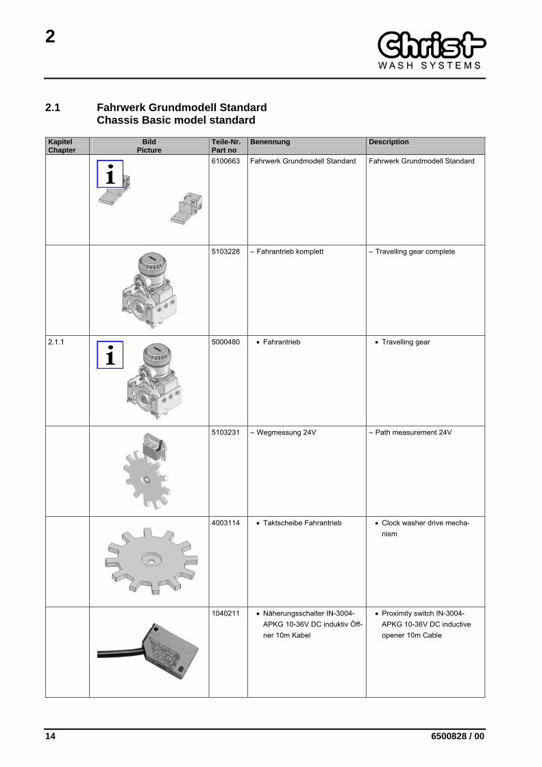
2.1 Fahrwerk Grundmodell Standard Chassis Basic model standard
Kapitel Chapter
Bild Picture
Teile-Nr. Part no
Benennung Description
6100663 Fahrwerk Grundmodell Standard Fahrwerk Grundmodell Standard
5103228 – Fahrantrieb komplett – Travelling gear complete
2.1.1
5000480 • Fahrantrieb • Travelling gear
5103231 – Wegmessung 24V – Path measurement 24V
4003114 • Taktscheibe Fahrantrieb • Clock washer drive mecha-nism
1040211 • Näherungsschalter IN-3004-APKG 10-36V DC induktiv Öff-ner 10m Kabel
• Proximity switch IN-3004-APKG 10-36V DC inductive opener 10m Cable
2
6500828 / 00 15
Kapitel Chapter
Bild Picture
Teile-Nr. Part no
Benennung Description
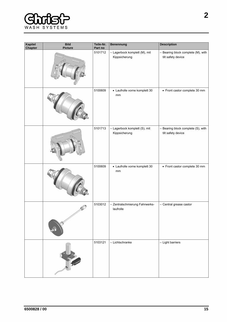
5101712 – Lagerbock komplett (M), mit Kippsicherung
– Bearing block complete (M), with tilt safety device
5100609 • Laufrolle vorne komplett 30 mm
• Front castor complete 30 mm
5101713 – Lagerbock komplett (S), mit Kippsicherung
– Bearing block complete (S), with tilt safety device
5100609 • Laufrolle vorne komplett 30 mm
• Front castor complete 30 mm
5103012 – Zentralschmierung Fahrwerks-laufrolle
– Central grease castor
5103121 – Lichtschranke – Light barriers
2
16 6500828 / 00
Kapitel Chapter
Bild Picture
Teile-Nr. Part no
Benennung Description
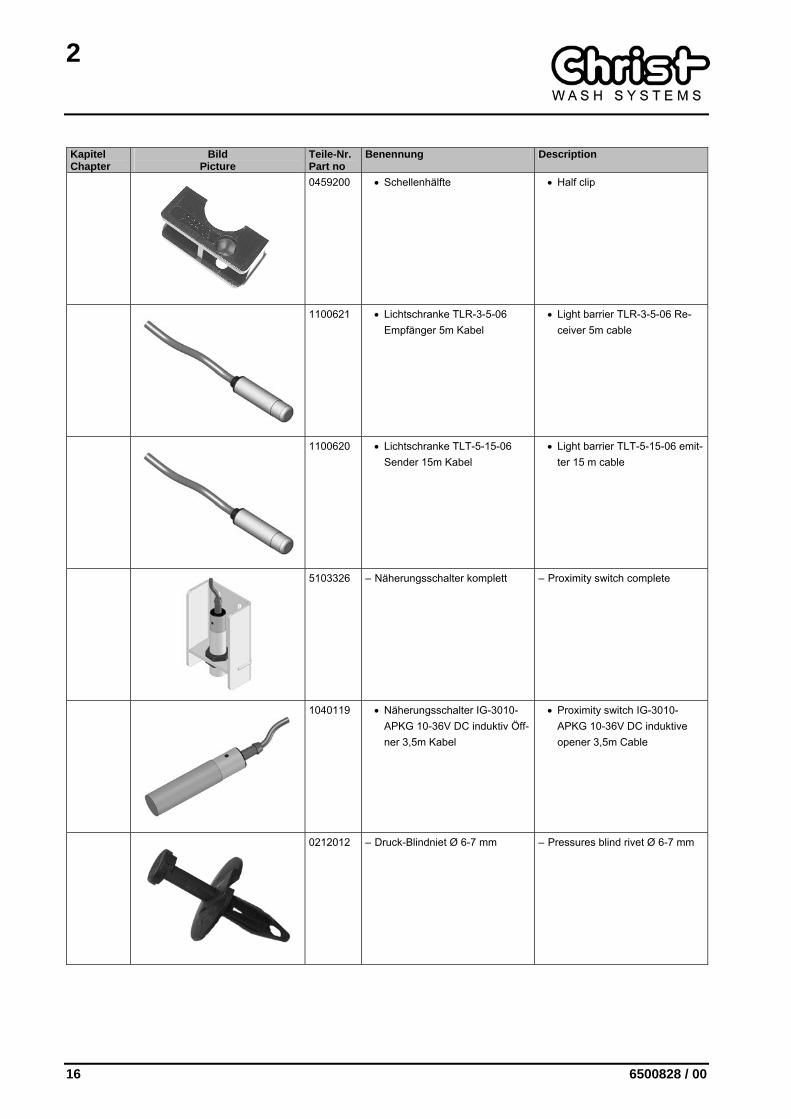
0459200 • Schellenhälfte • Half clip
1100621 • Lichtschranke TLR-3-5-06 Empfänger 5m Kabel
• Light barrier TLR-3-5-06 Re-ceiver 5m cable
1100620 • Lichtschranke TLT-5-15-06 Sender 15m Kabel
• Light barrier TLT-5-15-06 emit-ter 15 m cable
5103326 – Näherungsschalter komplett – Proximity switch complete
1040119 • Näherungsschalter IG-3010-APKG 10-36V DC induktiv Öff-ner 3,5m Kabel
• Proximity switch IG-3010-APKG 10-36V DC induktive opener 3,5m Cable
0212012 – Druck-Blindniet Ø 6-7 mm – Pressures blind rivet Ø 6-7 mm

2
6500828 / 00 17
2.1.1 Fahrantrieb Travelling gear
Kapitel Chapter
Bild Picture
Teile-Nr. Part no
Benennung Description
5000480 Fahrantrieb Travelling gear
5000114 – Fahrgetriebe I= 43 – Drive gear I= 43
5000470 – OC-Motor 0,55kW 230/400V 50Hz 1450 1/min
– OC-motor 0,55kW 230/400V 50Hz 1450 1/min
0908100 – Getriebeöl CLP 68 – Gear oil CLP 68
2
18 6500828 / 00
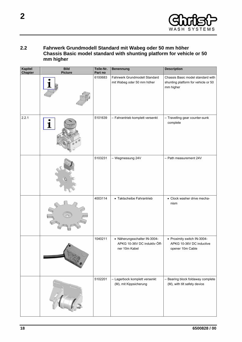
2.2 Fahrwerk Grundmodell Standard mit Wabeg oder 50 mm höher Chassis Basic model standard with shunting platform for vehicle or 50 mm higher
Kapitel Chapter
Bild Picture
Teile-Nr. Part no
Benennung Description
6100683 Fahrwerk Grundmodell Standard mit Wabeg oder 50 mm höher
Chassis Basic model standard with shunting platform for vehicle or 50 mm higher
2.2.1
5101639 – Fahrantrieb komplett versenkt – Travelling gear counter-sunk complete
5103231 – Wegmessung 24V – Path measurement 24V
4003114 • Taktscheibe Fahrantrieb • Clock washer drive mecha-nism
1040211 • Näherungsschalter IN-3004-APKG 10-36V DC induktiv Öff-ner 10m Kabel
• Proximity switch IN-3004-APKG 10-36V DC inductive opener 10m Cable
5102201 – Lagerbock komplett versenkt (M), mit Kippsicherung
– Bearing block foldaway complete (M), with tilt safety device

2
6500828 / 00 19
Kapitel Chapter
Bild Picture
Teile-Nr. Part no
Benennung Description
5100609 • Laufrolle vorne komplett 30 mm
• Front castor complete 30 mm
5102202 – Lagerbock komplett versenkt (S), mit Kippsicherung
– Bearing block foldaway complete (S), with tilt safety device
5100609 • Laufrolle vorne komplett 30 mm
• Front castor complete 30 mm
5103012 – Zentralschmierung Fahrwerks-laufrolle
– Central grease castor
5103121 – Lichtschranke – Light barriers
0459200 • Schellenhälfte • Half clip
2
20 6500828 / 00
Kapitel Chapter
Bild Picture
Teile-Nr. Part no
Benennung Description
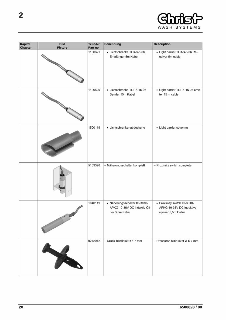
1100621 • Lichtschranke TLR-3-5-06 Empfänger 5m Kabel
• Light barrier TLR-3-5-06 Re-ceiver 5m cable
1100620 • Lichtschranke TLT-5-15-06 Sender 15m Kabel
• Light barrier TLT-5-15-06 emit-ter 15 m cable
1500119 • Lichtschrankenabdeckung • Light barrier covering
5103326 – Näherungsschalter komplett – Proximity switch complete
1040119 • Näherungsschalter IG-3010-APKG 10-36V DC induktiv Öff-ner 3,5m Kabel
• Proximity switch IG-3010-APKG 10-36V DC induktive opener 3,5m Cable
0212012 – Druck-Blindniet Ø 6-7 mm – Pressures blind rivet Ø 6-7 mm

2
6500828 / 00 21
2.2.1 Fahrantrieb komplett versenkt Travelling gear counter-sunk complete
Kapitel Chapter
Bild Picture
Teile-Nr. Part no
Benennung Description
5101639 Fahrantrieb komplett versenkt Travelling gear counter-sunk com-plete
2.1.1
5000480 – Fahrantrieb – Travelling gear
4002121 – Anschraubblech – Bolt-on plate
2
22 6500828 / 00
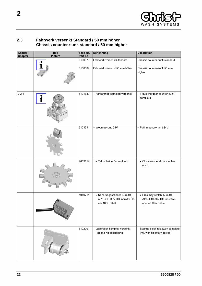
2.3 Fahrwerk versenkt Standard / 50 mm höher Chassis counter-sunk standard / 50 mm higher
Kapitel Chapter
Bild Picture
Teile-Nr. Part no
Benennung Description
6100673 6100684
Fahrwerk versenkt Standard Fahrwerk versenkt 50 mm höher
Chassis counter-sunk standard Chassis counter-sunk 50 mm higher
2.2.1
5101639 – Fahrantrieb komplett versenkt – Travelling gear counter-sunk complete
5103231 – Wegmessung 24V – Path measurement 24V
4003114 • Taktscheibe Fahrantrieb • Clock washer drive mecha-nism
1040211 • Näherungsschalter IN-3004-APKG 10-36V DC induktiv Öff-ner 10m Kabel
• Proximity switch IN-3004-APKG 10-36V DC inductive opener 10m Cable
5102201 – Lagerbock komplett versenkt (M), mit Kippsicherung
– Bearing block foldaway complete (M), with tilt safety device

2
6500828 / 00 23
Kapitel Chapter
Bild Picture
Teile-Nr. Part no
Benennung Description
5100609 • Laufrolle vorne komplett 30 mm
• Front castor complete 30 mm
5102202 – Lagerbock komplett versenkt (S), mit Kippsicherung
– Bearing block foldaway complete (S), with tilt safety device
5100609 • Laufrolle vorne komplett 30 mm
• Front castor complete 30 mm
5103012 – Zentralschmierung Fahrwerks-laufrolle
– Central grease castor
5103121 – Lichtschranke – Light barriers
0459200 • Schellenhälfte • Half clip

2
24 6500828 / 00
Kapitel Chapter
Bild Picture
Teile-Nr. Part no
Benennung Description
1100621 • Lichtschranke TLR-3-5-06 Empfänger 5m Kabel
• Light barrier TLR-3-5-06 Re-ceiver 5m cable
1100620 • Lichtschranke TLT-5-15-06 Sender 15m Kabel
• Light barrier TLT-5-15-06 emit-ter 15 m cable
1500119 • Lichtschrankenabdeckung • Light barrier covering
5103326 – Näherungsschalter komplett – Proximity switch complete
1040119 • Näherungsschalter IG-3010-APKG 10-36V DC induktiv Öff-ner 3,5m Kabel
• Proximity switch IG-3010-APKG 10-36V DC induktive opener 3,5m Cable
0212012 – Druck-Blindniet Ø 6-7 mm – Pressures blind rivet Ø 6-7 mm
3
6500828 / 00 25
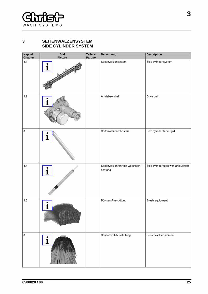
3 SEITENWALZENSYSTEM SIDE CYLINDER SYSTEM
Kapitel Chapter
Bild Picture
Teile-Nr. Part no
Benennung Description
3.1
Seitenwalzensystem Side cylinder system
3.2
Antriebseinheit Drive unit
3.3
Seitenwalzenrohr starr Side cylinder tube rigid
3.4
Seitenwalzenrohr mit Gelenkein-richtung
Side cylinder tube with articulation
3.5
Bürsten-Ausstattung Brush equipment
3.6
Sensotex II-Ausstattung Sensotex II equipment
3
26 6500828 / 00
Kapitel Chapter
Bild Picture
Teile-Nr. Part no
Benennung Description
3.7
Sensofil I-Ausstattung Sensofil I equipment

3
6500828 / 00 27
3.1 Seitenwalzensystem Side cylinder system
Kapitel Chapter
Bild Picture
Teile-Nr. Part no
Benennung Description
5400920 Seitenwalzensystem Gelenkein-richtung
Side cylinder system articulation
3.1.1
5103520 – Laufkatze I (S) – Trolley I (S)
3.1.1
5103521 – Laufkatze I (M) – Trolley I (M)
5000381 – Öffnungsmotor komplett – Side brush traverse motor and gearbox unit (spur wheel with 21 teeth)
5300394 • Antriebseinheit • Drive unit
1405901 5600398
• Stirnrad Z=21
• Reparatursatz Stirnrad Z=21 (Stirnrad, Gewindestift, Pass-feder)
• Toothed wheel T=21
• Repair kit toothed wheel T=21 (toothed wheel, thread pin, feather key)
3
28 6500828 / 00
Kapitel Chapter
Bild Picture
Teile-Nr. Part no
Benennung Description
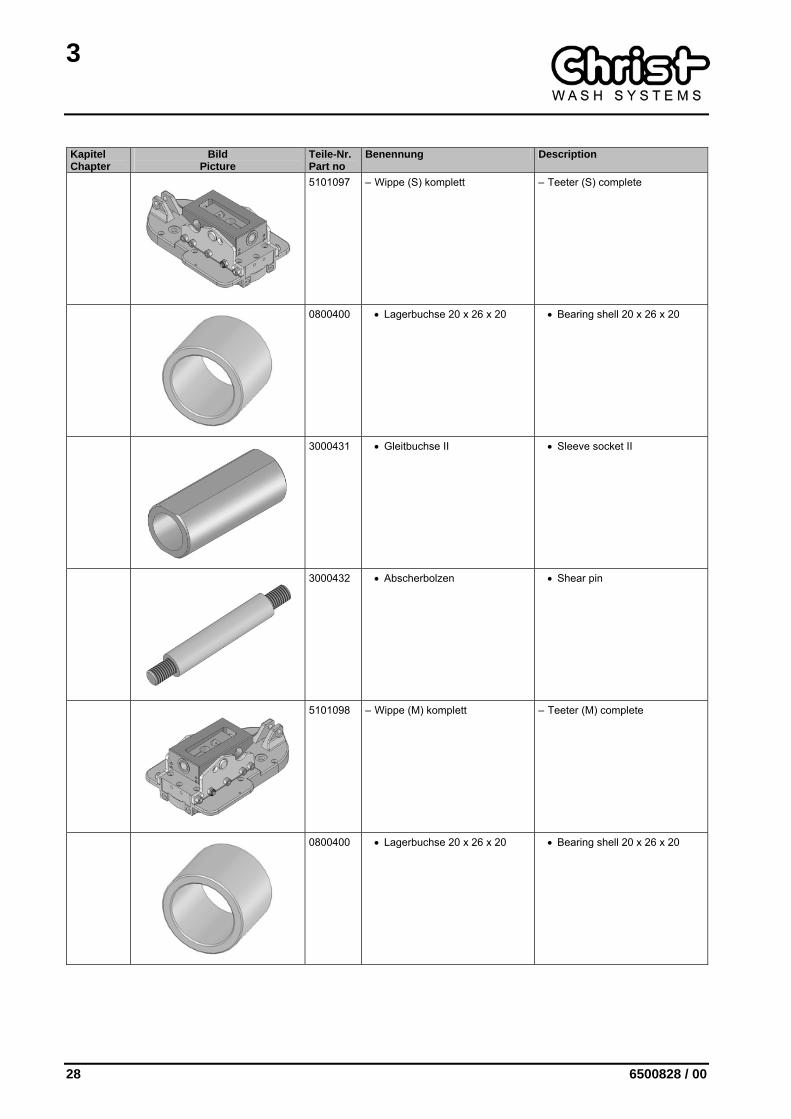
5101097 – Wippe (S) komplett – Teeter (S) complete
0800400 • Lagerbuchse 20 x 26 x 20 • Bearing shell 20 x 26 x 20
3000431 • Gleitbuchse II • Sleeve socket II
3000432 • Abscherbolzen • Shear pin
5101098 – Wippe (M) komplett – Teeter (M) complete
0800400 • Lagerbuchse 20 x 26 x 20 • Bearing shell 20 x 26 x 20

3
6500828 / 00 29
Kapitel Chapter
Bild Picture
Teile-Nr. Part no
Benennung Description
3000431 • Gleitbuchse II • Sleeve socket II
3000432 • Abscherbolzen • Shear pin
6200249 – Einbauteile – Build-in parts
5100786 • Anschlagpuffer • Stop buffer
3000424 • Gelenkbolzen • Articulated bolt
4202400 • Achshalter Welle-Gelenkkopf • Axle support shaft-articulated top
3
30 6500828 / 00
Kapitel Chapter
Bild Picture
Teile-Nr. Part no
Benennung Description
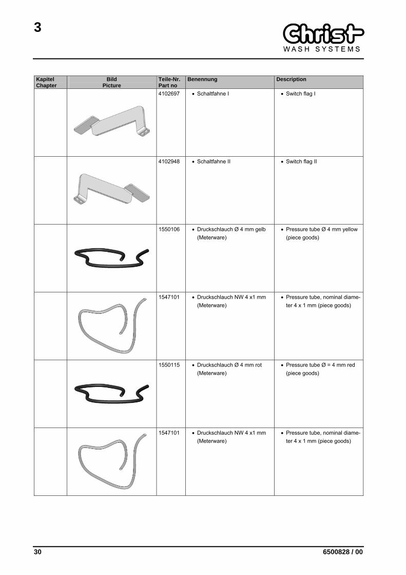
4102697 • Schaltfahne I • Switch flag I
4102948 • Schaltfahne II • Switch flag II
1550106 • Druckschlauch Ø 4 mm gelb (Meterware)
• Pressure tube Ø 4 mm yellow (piece goods)
1547101 • Druckschlauch NW 4 x1 mm (Meterware)
• Pressure tube, nominal diame-ter 4 x 1 mm (piece goods)
1550115 • Druckschlauch Ø 4 mm rot (Meterware)
• Pressure tube Ø = 4 mm red (piece goods)
1547101 • Druckschlauch NW 4 x1 mm (Meterware)
• Pressure tube, nominal diame-ter 4 x 1 mm (piece goods)
3
6500828 / 00 31
Kapitel Chapter
Bild Picture
Teile-Nr. Part no
Benennung Description
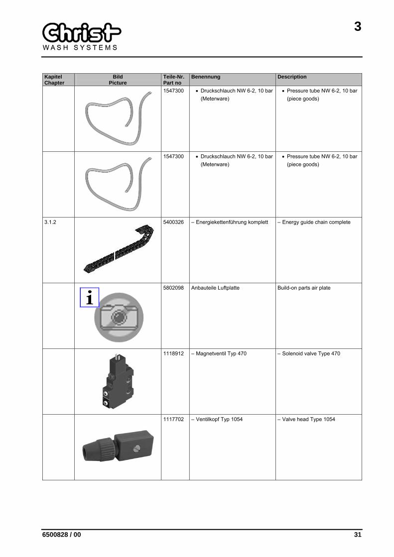
1547300 • Druckschlauch NW 6-2, 10 bar (Meterware)
• Pressure tube NW 6-2, 10 bar (piece goods)
1547300 • Druckschlauch NW 6-2, 10 bar (Meterware)
• Pressure tube NW 6-2, 10 bar (piece goods)
3.1.2
5400326 – Energiekettenführung komplett – Energy guide chain complete
5802098 Anbauteile Luftplatte Build-on parts air plate
1118912 – Magnetventil Typ 470 – Solenoid valve Type 470
1117702 – Ventilkopf Typ 1054 – Valve head Type 1054
3
32 6500828 / 00
Kapitel Chapter
Bild Picture
Teile-Nr. Part no
Benennung Description
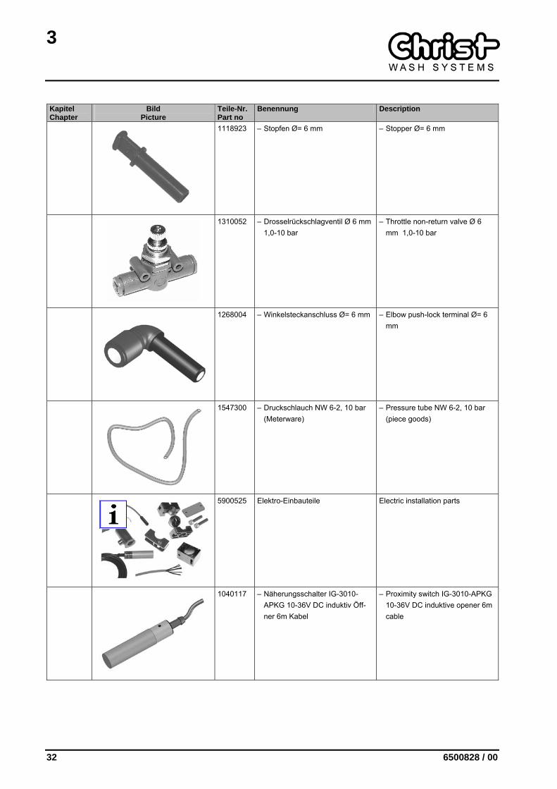
1118923 – Stopfen Ø= 6 mm – Stopper Ø= 6 mm
1310052 – Drosselrückschlagventil Ø 6 mm 1,0-10 bar
– Throttle non-return valve Ø 6 mm 1,0-10 bar
1268004 – Winkelsteckanschluss Ø= 6 mm – Elbow push-lock terminal Ø= 6 mm
1547300 – Druckschlauch NW 6-2, 10 bar (Meterware)
– Pressure tube NW 6-2, 10 bar (piece goods)
5900525 Elektro-Einbauteile Electric installation parts
1040117 – Näherungsschalter IG-3010-APKG 10-36V DC induktiv Öff-ner 6m Kabel
– Proximity switch IG-3010-APKG 10-36V DC induktive opener 6m cable
3
6500828 / 00 33
Kapitel Chapter
Bild Picture
Teile-Nr. Part no
Benennung Description
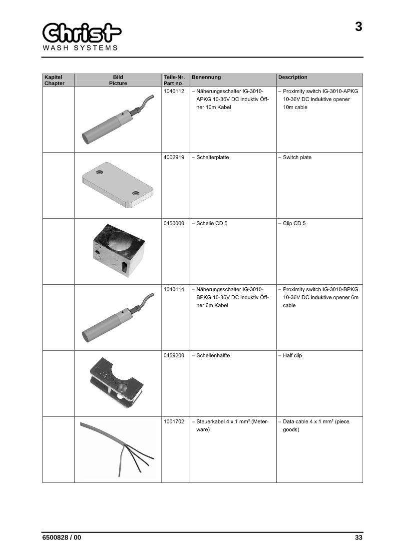
1040112 – Näherungsschalter IG-3010-APKG 10-36V DC induktiv Öff-ner 10m Kabel
– Proximity switch IG-3010-APKG 10-36V DC induktive opener 10m cable
4002919 – Schalterplatte – Switch plate
0450000 – Schelle CD 5 – Clip CD 5
1040114 – Näherungsschalter IG-3010-BPKG 10-36V DC induktiv Öff-ner 6m Kabel
– Proximity switch IG-3010-BPKG 10-36V DC induktive opener 6m cable
0459200 – Schellenhälfte – Half clip
1001702 – Steuerkabel 4 x 1 mm² (Meter-ware)
– Data cable 4 x 1 mm² (piece goods)
3
34 6500828 / 00
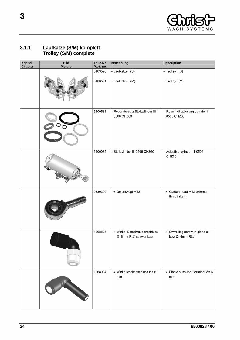
3.1.1 Laufkatze (S/M) komplett Trolley (S/M) complete
Kapitel Chapter
Bild Picture
Teile-Nr. Part.-no.
Benennung Description
5103520 5103521
– Laufkatze I (S)
– Laufkatze I (M)
– Trolley I (S)
– Trolley I (M)
5600581 – Reparatursatz Stellzylinder III-0506 CHZ60
– Repair-kit adjusting cylinder III-0506 CHZ60
5500085 – Stellzylinder III-0506 CHZ60 – Adjusting cylinder III-0506 CHZ60
0830300 • Gelenkkopf M12 • Cardan head M12 external thread right
1268825 • Winkel-Einschraubanschluss Ø=6mm-R⅛“ schwenkbar
• Swivelling screw-in gland el-bow Ø=6mm-R⅛“
1268004 • Winkelsteckanschluss Ø= 6 mm
• Elbow push-lock terminal Ø= 6 mm
3
6500828 / 00 35
Kapitel Chapter
Bild Picture
Teile-Nr. Part.-no.
Benennung Description
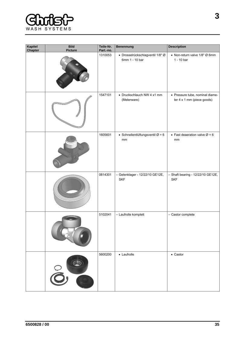
1310053 • Drosselrückschlagventil 1/8" Ø 6mm 1 - 10 bar
• Non-return valve 1/8" Ø 6mm 1 - 10 bar
1547101 • Druckschlauch NW 4 x1 mm (Meterware)
• Pressure tube, nominal diame-ter 4 x 1 mm (piece goods)
1605601 • Schnellentlüftungsventil Ø = 6 mm
• Fast deaeration valve Ø = 6 mm
0814301 – Gelenklager - 12/22/10 GE12E, SKF
– Shaft bearing - 12/22/10 GE12E, SKF
5102041 – Laufrolle komplett – Castor complete
5600200 • Laufrolle • Castor
3
36 6500828 / 00
Kapitel Chapter
Bild Picture
Teile-Nr. Part.-no.
Benennung Description
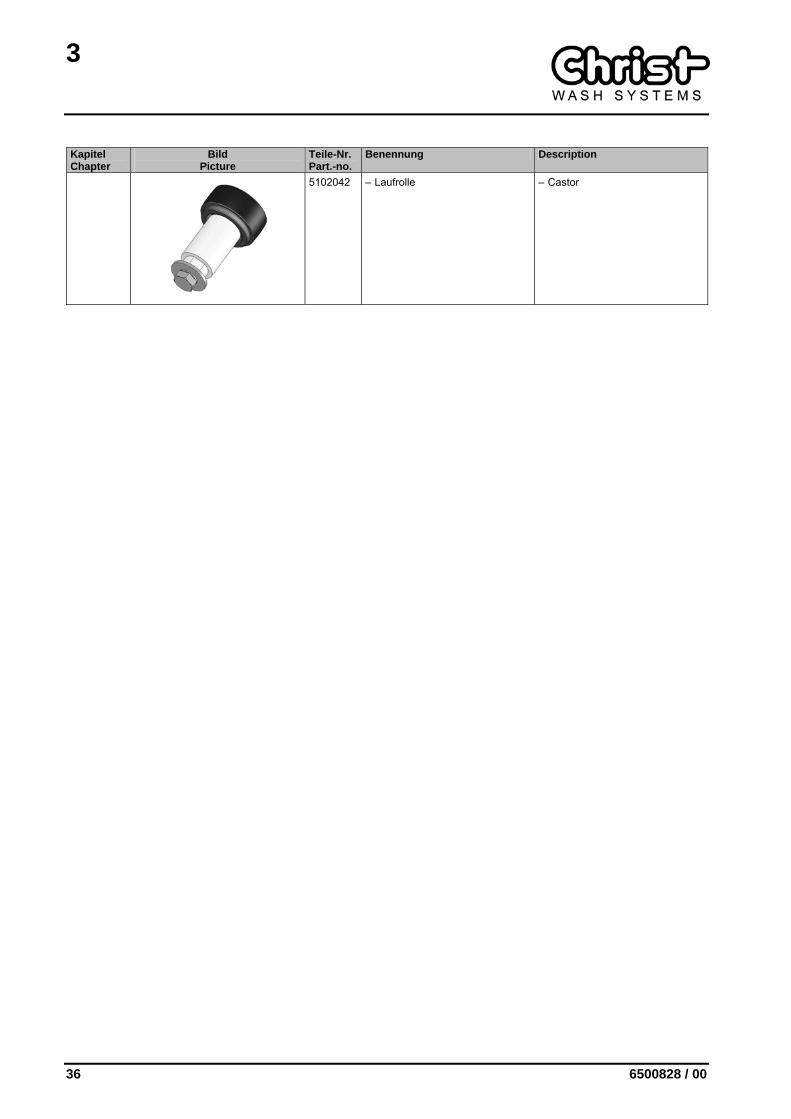
5102042 – Laufrolle – Castor
3
6500828 / 00 37
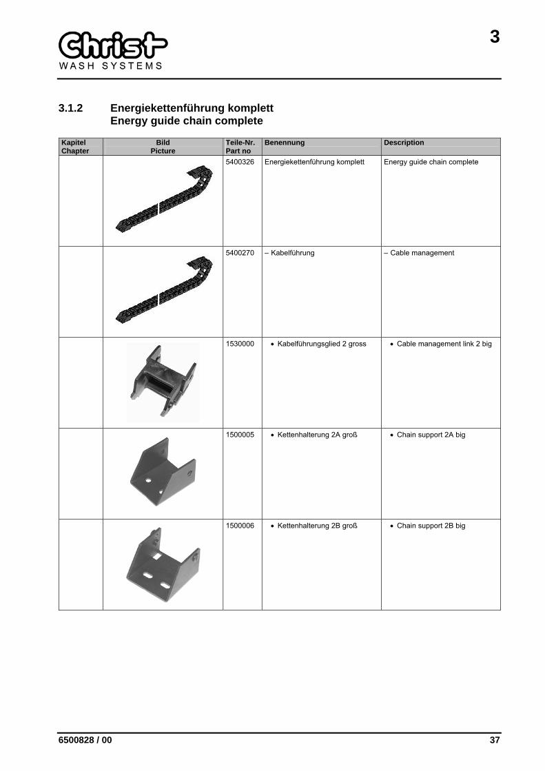
3.1.2 Energiekettenführung komplett Energy guide chain complete
Kapitel Chapter
Bild Picture
Teile-Nr. Part no
Benennung Description
5400326 Energiekettenführung komplett Energy guide chain complete
5400270 – Kabelführung – Cable management
1530000 • Kabelführungsglied 2 gross • Cable management link 2 big
1500005 • Kettenhalterung 2A groß • Chain support 2A big
1500006 • Kettenhalterung 2B groß • Chain support 2B big
3
38 6500828 / 00
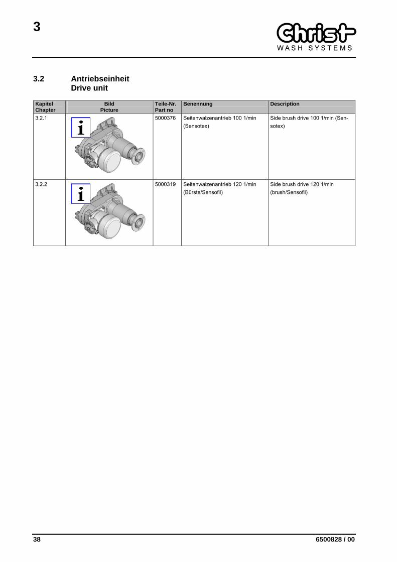
3.2 Antriebseinheit Drive unit
Kapitel Chapter
Bild Picture
Teile-Nr. Part no
Benennung Description
3.2.1
5000376 Seitenwalzenantrieb 100 1/min (Sensotex)
Side brush drive 100 1/min (Sen-sotex)
3.2.2
5000319 Seitenwalzenantrieb 120 1/min (Bürste/Sensofil)
Side brush drive 120 1/min (brush/Sensofil)
3
6500828 / 00 39
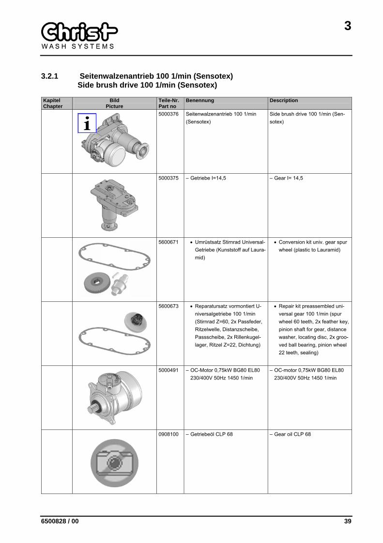
3.2.1 Seitenwalzenantrieb 100 1/min (Sensotex) Side brush drive 100 1/min (Sensotex)
Kapitel Chapter
Bild Picture
Teile-Nr. Part no
Benennung Description
5000376 Seitenwalzenantrieb 100 1/min (Sensotex)
Side brush drive 100 1/min (Sen-sotex)
5000375 – Getriebe I=14,5 – Gear I= 14,5
5600671 • Umrüstsatz Stirnrad Universal-Getriebe (Kunststoff auf Laura-mid)
• Conversion kit univ. gear spur wheel (plastic to Lauramid)
5600673 • Reparatursatz vormontiert U-niversalgetriebe 100 1/min (Stirnrad Z=60, 2x Passfeder, Ritzelwelle, Distanzscheibe, Passscheibe, 2x Rillenkugel-lager, Ritzel Z=22, Dichtung)
• Repair kit preassembled uni-versal gear 100 1/min (spur wheel 60 teeth, 2x feather key, pinion shaft for gear, distance washer, locating disc, 2x groo-ved ball bearing, pinion wheel 22 teeth, sealing)
5000491 – OC-Motor 0,75kW BG80 EL80 230/400V 50Hz 1450 1/min
– OC-motor 0,75kW BG80 EL80 230/400V 50Hz 1450 1/min
0908100 – Getriebeöl CLP 68 – Gear oil CLP 68

3
40 6500828 / 00
Kapitel Chapter
Bild Picture
Teile-Nr. Part no
Benennung Description
1274100 – O-Ring 100 x 3 mm – O-ring 100 x 3 mm
3
6500828 / 00 41
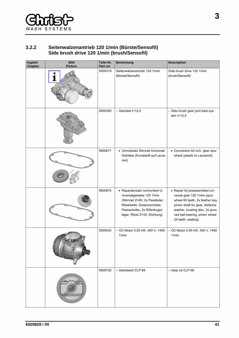
3.2.2 Seitenwalzenantrieb 120 1/min (Bürste/Sensofil) Side brush drive 120 1/min (brush/Sensofil)
Kapitel Chapter
Bild Picture
Teile-Nr. Part no
Benennung Description
5000319 Seitenwalzenantrieb 120 1/min (Bürste/Sensofil)
Side brush drive 120 1/min (brush/Sensofil)
5000350 – Getriebe I=12,5 – Side brush gear joint tube sys-tem I=12,5
5600671 • Umrüstsatz Stirnrad Universal-Getriebe (Kunststoff auf Laura-mid)
• Conversion kit univ. gear spur wheel (plastic to Lauramid)
5600674 • Reparatursatz vormontiert U-niversalgetriebe 120 1/min (Stirnrad Z=60, 2x Passfeder, Ritzelwelle, Distanzscheibe, Passscheibe, 2x Rillenkugel-lager, Ritzel Z=24, Dichtung)
• Repair kit preassembled uni-versal gear 120 1/min (spur wheel 60 teeth, 2x feather key, pinion shaft for gear, distance washer, locating disc, 2x groo-ved ball bearing, pinion wheel 24 teeth, sealing)
5000043 – OC-Motor 0,55 kW, 400 V, 1450 1/min
– OC-Motor 0,55 kW, 400 V, 1450 1/min
0908100 – Getriebeöl CLP 68 – Gear oil CLP 68
3
42 6500828 / 00
Kapitel Chapter
Bild Picture
Teile-Nr. Part no
Benennung Description
1274100 – O-Ring 100 x 3 mm – O-ring 100 x 3 mm
3
6500828 / 00 43
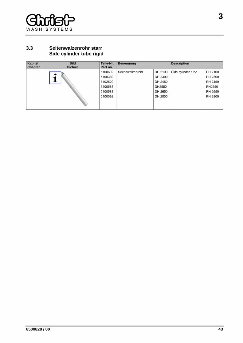
3.3 Seitenwalzenrohr starr Side cylinder tube rigid
Kapitel Chapter
Bild Picture
Teile-Nr. Part no
Benennung Description
5100602 5100380 5102520 5100588 5100581 5100592
Seitenwalzenrohr DH 2100 DH 2300 DH 2450 DH2550 DH 2650 DH 2800
Side cylinder tube PH 2100 PH 2300 PH 2450 PH2550 PH 2650 PH 2800
3
44 6500828 / 00
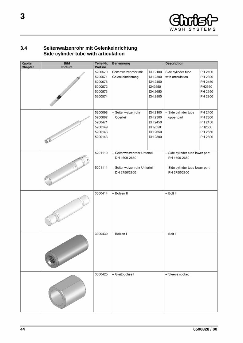
3.4 Seitenwalzenrohr mit Gelenkeinrichtung Side cylinder tube with articulation
Kapitel Chapter
Bild Picture
Teile-Nr. Part no
Benennung Description
5200570 5200571 5200676 5200572 5200573 5200574
Seitenwalzenrohr mit Gelenkeinrichtung
DH 2100 DH 2300 DH 2450 DH2550 DH 2650 DH 2800
Side cylinder tube with articulation
PH 2100 PH 2300 PH 2450 PH2550 PH 2650 PH 2800
5200098 5200087 5200471 5200149 5200143 5200143
– Seitenwalzenrohr Oberteil
DH 2100 DH 2300 DH 2450 DH2550 DH 2650 DH 2800
– Side cylinder tube upper part
PH 2100 PH 2300 PH 2450 PH2550 PH 2650 PH 2800
5201110 5201111
– Seitenwalzenrohr Unterteil DH 1600-2650
– Seitenwalzenrohr Unterteil DH 2750/2800
– Side cylinder tube lower part PH 1600-2650
– Side cylinder tube lower part PH 2750/2800
3000414 – Bolzen II – Bolt II
3000430 – Bolzen I – Bolt I
3000425 – Gleitbuchse I – Sleeve socket I
3
6500828 / 00 45
Kapitel Chapter
Bild Picture
Teile-Nr. Part no
Benennung Description
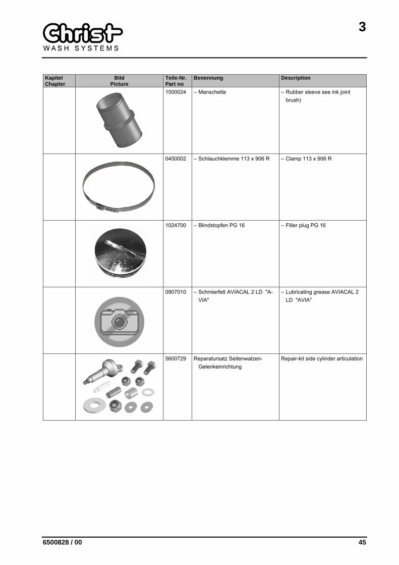
1500024 – Manschette – Rubber sleeve see ink joint brush)
0450002 – Schlauchklemme 113 x 906 R – Clamp 113 x 906 R
1024700 – Blindstopfen PG 16 – Filler plug PG 16
0907010 – Schmierfett AVIACAL 2 LD "A-VIA"
– Lubricating grease AVIACAL 2 LD "AVIA"
5600729 Reparatursatz Seitenwalzen-Gelenkeinrichtung
Repair-kit side cylinder articulation
3
46 6500828 / 00
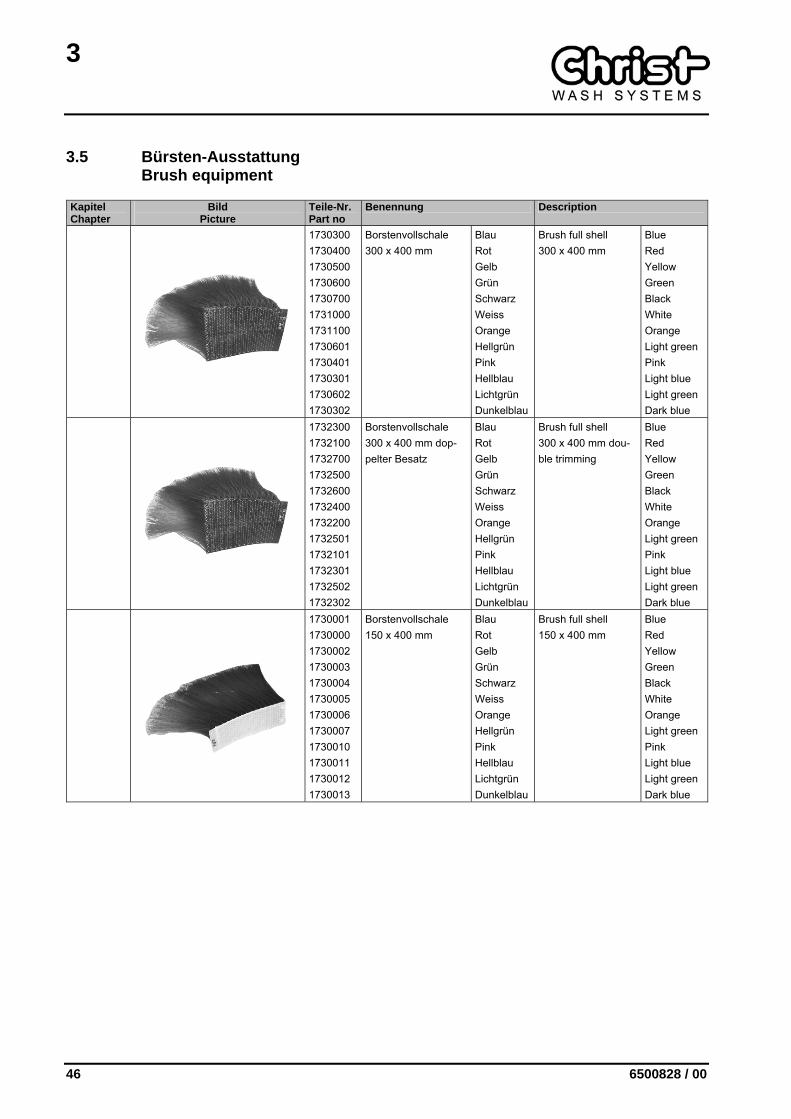
3.5 Bürsten-Ausstattung Brush equipment
Kapitel Chapter
Bild Picture
Teile-Nr. Part no
Benennung Description
1730300 1730400 1730500 1730600 1730700 1731000 1731100 1730601 1730401 1730301 1730602 1730302
Borstenvollschale 300 x 400 mm
Blau Rot Gelb Grün Schwarz Weiss Orange Hellgrün Pink Hellblau Lichtgrün Dunkelblau
Brush full shell 300 x 400 mm
Blue Red Yellow Green Black White Orange Light green Pink Light blue Light green Dark blue
1732300 1732100 1732700 1732500 1732600 1732400 1732200 1732501 1732101 1732301 1732502 1732302
Borstenvollschale 300 x 400 mm dop-pelter Besatz
Blau Rot Gelb Grün Schwarz Weiss Orange Hellgrün Pink Hellblau Lichtgrün Dunkelblau
Brush full shell 300 x 400 mm dou-ble trimming
Blue Red Yellow Green Black White Orange Light green Pink Light blue Light green Dark blue
1730001 1730000 1730002 1730003 1730004 1730005 1730006 1730007 1730010 1730011 1730012 1730013
Borstenvollschale 150 x 400 mm
Blau Rot Gelb Grün Schwarz Weiss Orange Hellgrün Pink Hellblau Lichtgrün Dunkelblau
Brush full shell 150 x 400 mm
Blue Red Yellow Green Black White Orange Light green Pink Light blue Light green Dark blue

3
6500828 / 00 47
3.6 Sensotex II-Ausstattung Sensotex II equipment
Kapitel Chapter
Bild Picture
Teile-Nr. Part no
Benennung Description
Sensotex II-Ausstattung Sensotex II equipment
1734600 1734610 1734620 1734630 1734650 1734651
– Textil Vollschale 300 x 400 mm mit Stützring blau rot gelb grün schwarz grau
– Textile full shell 300 x 400 mm with supporting ring blue red yellow green black grey
1734500 1734510 1734520 1734530 1734550 1734551
– Textil Vollschale Spaghetti 300 x 400 mm blau rot gelb grün schwarz grau
– Textile full shell spaghetti 300 x 400 mm blue red yellow green black grey
1734400 1734410 1734420 1734430 1734450 1734451
– Textil Vollschale Spaghetti 150 x 400 mm blau rot gelb grün schwarz grau
– Textile full shell spaghetti 150 x 400 mm blue red yellow green black grey
1734300 1734310 1734320 1734330 1734350 1734351
– Textil-Vollschale Spaghetti 50 x 400 mm blau rot gelb grün schwarz grau
– Textile-fullshell spaghetti 50 x 400 mm blue red yellow green black grey
5700453 – Anbauteile Gelenkbürstenver-längerung 50 mm; DH 2050 – 2600 (nur bei Gelenkeinrichtung)
– Built-on parts cardanbrush-lengthening 50 mm; PH 2050 – 2600 (only for cardan device)
3
48 6500828 / 00
Kapitel Chapter
Bild Picture
Teile-Nr. Part no
Benennung Description
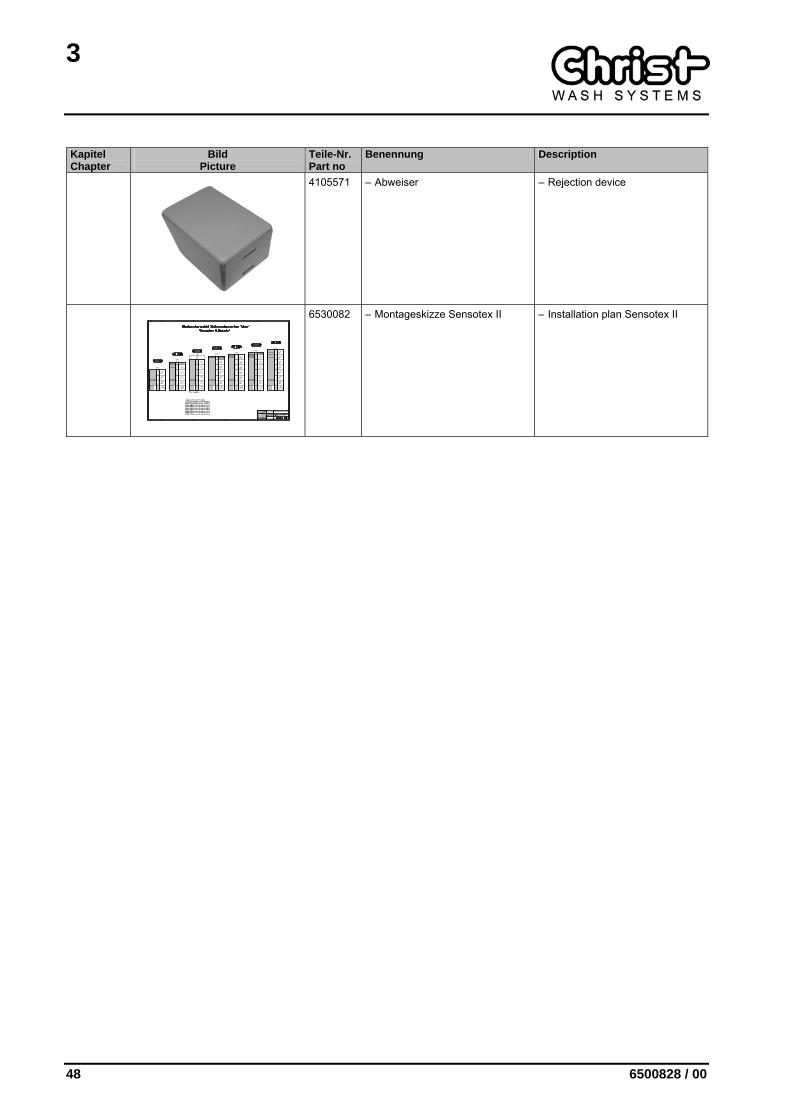
4105571 – Abweiser – Rejection device
6530082 – Montageskizze Sensotex II – Installation plan Sensotex II
3
6500828 / 00 49
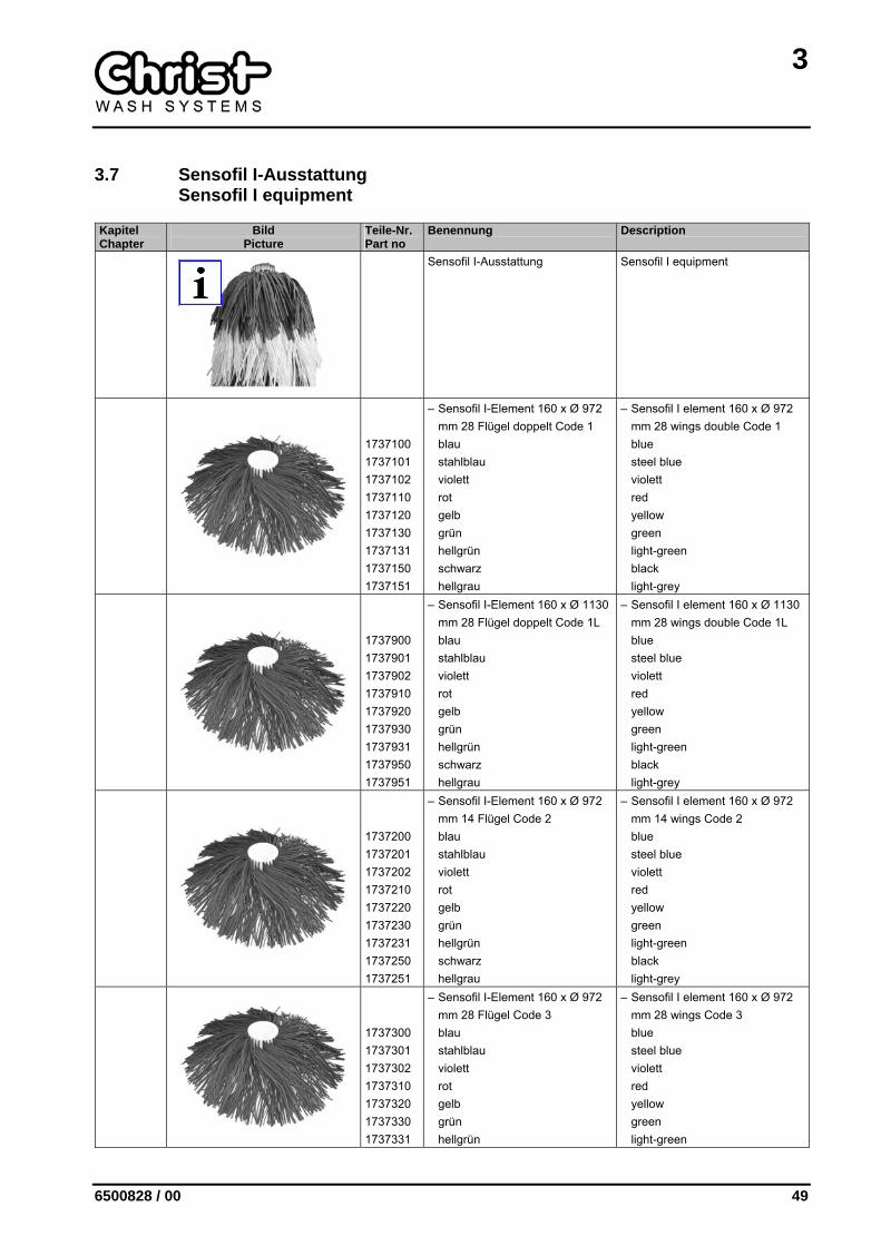
3.7 Sensofil I-Ausstattung Sensofil I equipment
Kapitel Chapter
Bild Picture
Teile-Nr. Part no
Benennung Description
Sensofil I-Ausstattung Sensofil I equipment
1737100 1737101 1737102 1737110 1737120 1737130 1737131 1737150 1737151
– Sensofil I-Element 160 x Ø 972 mm 28 Flügel doppelt Code 1 blau stahlblau violett rot gelb grün hellgrün schwarz hellgrau
– Sensofil I element 160 x Ø 972 mm 28 wings double Code 1 blue steel blue violett red yellow green light-green black light-grey
1737900 1737901 1737902 1737910 1737920 1737930 1737931 1737950 1737951
– Sensofil I-Element 160 x Ø 1130 mm 28 Flügel doppelt Code 1L blau stahlblau violett rot gelb grün hellgrün schwarz hellgrau
– Sensofil I element 160 x Ø 1130 mm 28 wings double Code 1L blue steel blue violett red yellow green light-green black light-grey
1737200 1737201 1737202 1737210 1737220 1737230 1737231 1737250 1737251
– Sensofil I-Element 160 x Ø 972 mm 14 Flügel Code 2 blau stahlblau violett rot gelb grün hellgrün schwarz hellgrau
– Sensofil I element 160 x Ø 972 mm 14 wings Code 2 blue steel blue violett red yellow green light-green black light-grey
1737300 1737301 1737302 1737310 1737320 1737330 1737331
– Sensofil I-Element 160 x Ø 972 mm 28 Flügel Code 3 blau stahlblau violett rot gelb grün hellgrün
– Sensofil I element 160 x Ø 972 mm 28 wings Code 3 blue steel blue violett red yellow green light-green
3
50 6500828 / 00
Kapitel Chapter
Bild Picture
Teile-Nr. Part no
Benennung Description
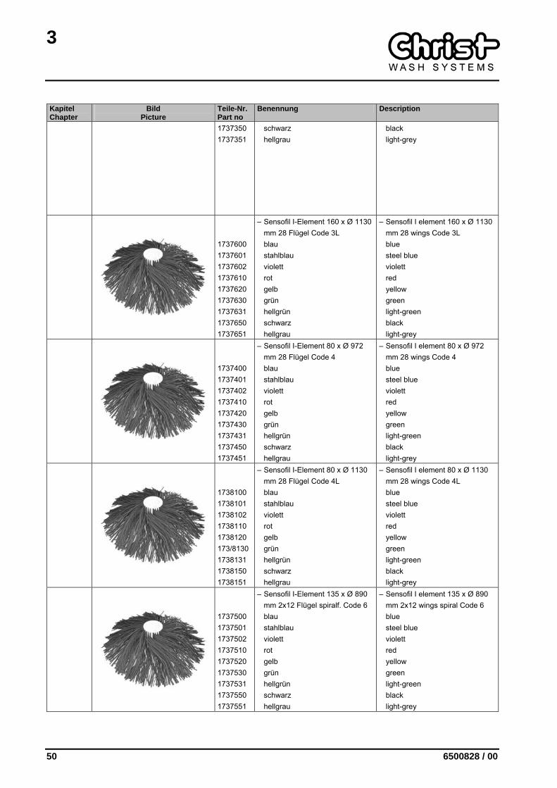
1737350 1737351
schwarz hellgrau
black light-grey
1737600 1737601 1737602 1737610 1737620 1737630 1737631 1737650 1737651
– Sensofil I-Element 160 x Ø 1130 mm 28 Flügel Code 3L blau stahlblau violett rot gelb grün hellgrün schwarz hellgrau
– Sensofil I element 160 x Ø 1130 mm 28 wings Code 3L blue steel blue violett red yellow green light-green black light-grey
1737400 1737401 1737402 1737410 1737420 1737430 1737431 1737450 1737451
– Sensofil I-Element 80 x Ø 972 mm 28 Flügel Code 4 blau stahlblau violett rot gelb grün hellgrün schwarz hellgrau
– Sensofil I element 80 x Ø 972 mm 28 wings Code 4 blue steel blue violett red yellow green light-green black light-grey
1738100 1738101 1738102 1738110 1738120 173/8130 1738131 1738150 1738151
– Sensofil I-Element 80 x Ø 1130 mm 28 Flügel Code 4L blau stahlblau violett rot gelb grün hellgrün schwarz hellgrau
– Sensofil I element 80 x Ø 1130 mm 28 wings Code 4L blue steel blue violett red yellow green light-green black light-grey
1737500 1737501 1737502 1737510 1737520 1737530 1737531 1737550 1737551
– Sensofil I-Element 135 x Ø 890 mm 2x12 Flügel spiralf. Code 6 blau stahlblau violett rot gelb grün hellgrün schwarz hellgrau
– Sensofil I element 135 x Ø 890 mm 2x12 wings spiral Code 6 blue steel blue violett red yellow green light-green black light-grey
3
6500828 / 00 51
Kapitel Chapter
Bild Picture
Teile-Nr. Part no
Benennung Description
6530177 – Montageskizze Sensofil I-Besatz – Installation drawing Sensofil I trimmimg

4
6500828 / 00 53
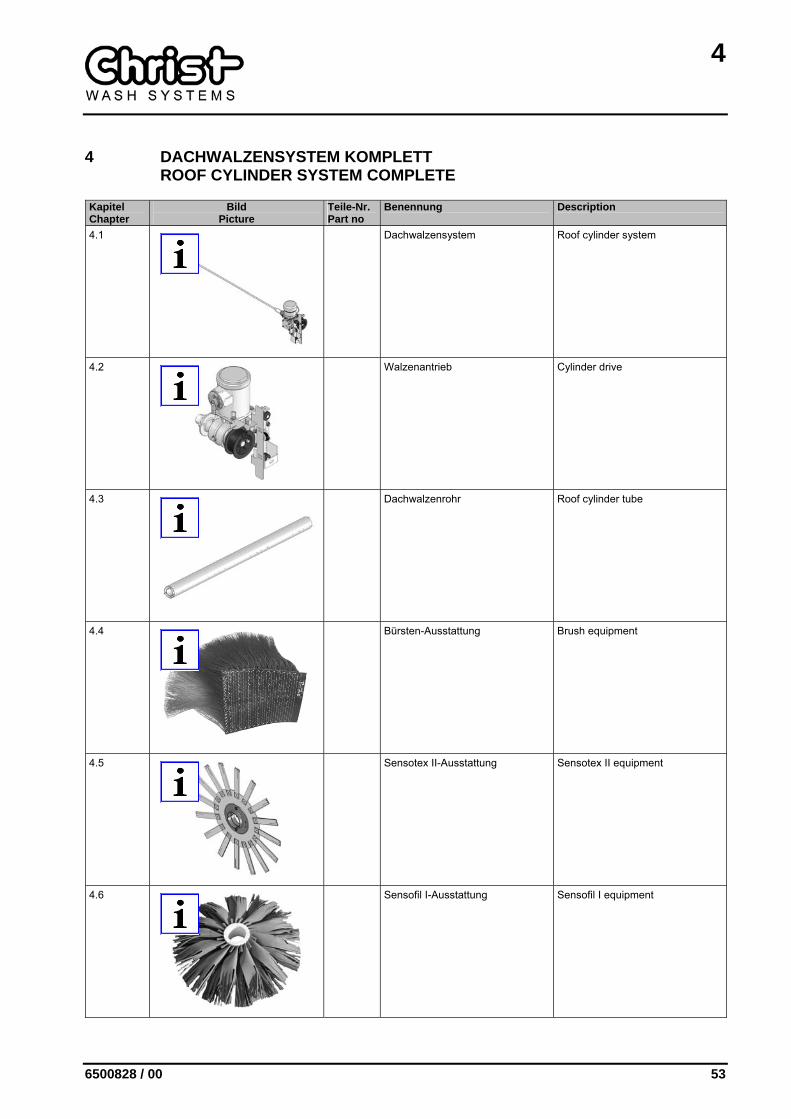
4 DACHWALZENSYSTEM KOMPLETT ROOF CYLINDER SYSTEM COMPLETE
Kapitel Chapter
Bild Picture
Teile-Nr. Part no
Benennung Description
4.1
Dachwalzensystem Roof cylinder system
4.2
Walzenantrieb Cylinder drive
4.3
Dachwalzenrohr Roof cylinder tube
4.4
Bürsten-Ausstattung Brush equipment
4.5
Sensotex II-Ausstattung Sensotex II equipment
4.6
Sensofil I-Ausstattung Sensofil I equipment
4
54 6500828 / 00
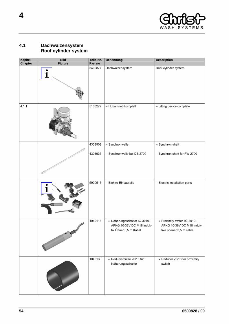
4.1 Dachwalzensystem Roof cylinder system
Kapitel Chapter
Bild Picture
Teile-Nr. Part no
Benennung Description
5400877 Dachwalzensystem Roof cylinder system
4.1.1
5103277 – Hubantrieb komplett – Lifting device complete
4303908 4303936
– Synchronwelle
– Synchronwelle bei DB 2700
– Synchron shaft
– Synchron shaft for PW 2700
5900513 – Elektro-Einbauteile – Electric installation parts
1040118 • Näherungsschalter IG-3010-APKG 10-36V DC M18 induk-tiv Öffner 3,5 m Kabel
• Proximity switch IG-3010-APKG 10-36V DC M18 induk-tive opener 3,5 m cable
1040130 • Reduzierhülse 20/18 für Näherungsschalter
• Reducer 20/18 for proximity switch
4
6500828 / 00 55
Kapitel Chapter
Bild Picture
Teile-Nr. Part no
Benennung Description
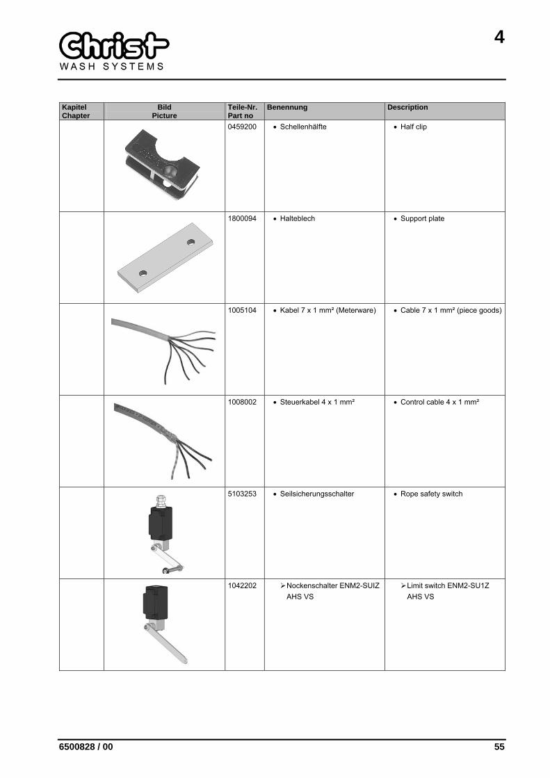
0459200 • Schellenhälfte • Half clip
1800094 • Halteblech • Support plate
1005104 • Kabel 7 x 1 mm² (Meterware) • Cable 7 x 1 mm² (piece goods)
1008002 • Steuerkabel 4 x 1 mm² • Control cable 4 x 1 mm²
5103253 • Seilsicherungsschalter • Rope safety switch
1042202 Nockenschalter ENM2-SUIZ AHS VS
Limit switch ENM2-SU1Z AHS VS
4
56 6500828 / 00
Kapitel Chapter
Bild Picture
Teile-Nr. Part no
Benennung Description
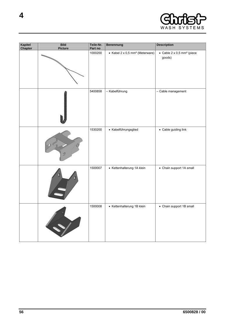
1000200 • Kabel 2 x 0,5 mm² (Meterware) • Cable 2 x 0,5 mm² (piece goods)
5400858 – Kabelführung – Cable management
1530200 • Kabelführungsglied • Cable guiding link
1500007 • Kettenhalterung 1A klein • Chain support 1A small
1500008 • Kettenhalterung 1B klein • Chain support 1B small
4
6500828 / 00 57
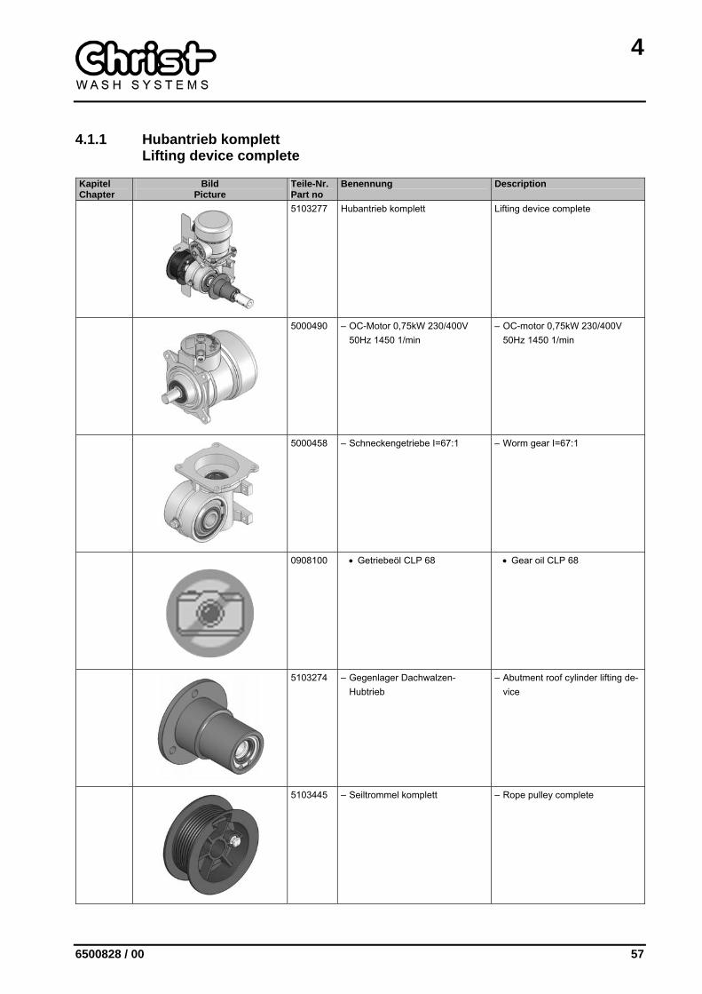
4.1.1 Hubantrieb komplett Lifting device complete
Kapitel Chapter
Bild Picture
Teile-Nr. Part no
Benennung Description
5103277 Hubantrieb komplett Lifting device complete
5000490 – OC-Motor 0,75kW 230/400V 50Hz 1450 1/min
– OC-motor 0,75kW 230/400V 50Hz 1450 1/min
5000458 – Schneckengetriebe I=67:1 – Worm gear I=67:1
0908100 • Getriebeöl CLP 68 • Gear oil CLP 68
5103274 – Gegenlager Dachwalzen-Hubtrieb
– Abutment roof cylinder lifting de-vice
5103445 – Seiltrommel komplett – Rope pulley complete

4
58 6500828 / 00
Kapitel Chapter
Bild Picture
Teile-Nr. Part no
Benennung Description
1702920 – Drahtseil 4 x 4000 mm – Wire rope 4 x 4000 mm
5100148 – Laufschlitten – Carriage
4109057 – Schaltfahne Hubtrieb – Switch lug lifting device
4300824 – Fallsicherung links – Drop safety device left/right
3001611 – Kupplung 20 – Coupling 20
4
6500828 / 00 59
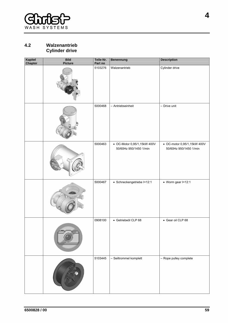
4.2 Walzenantrieb Cylinder drive
Kapitel Chapter
Bild Picture
Teile-Nr. Part no
Benennung Description
5103276 Walzenantrieb Cylinder drive
5000468 – Antriebseinheit – Drive unit
5000463 • OC-Motor 0,95/1,15kW 400V 50/60Hz 950/1450 1/min
• OC-motor 0,95/1,15kW 400V 50/60Hz 950/1450 1/min
5000467 • Schneckengetriebe I=12:1 • Worm gear I=12:1
0908100 • Getriebeöl CLP 68 • Gear oil CLP 68
5103445 – Seiltrommel komplett – Rope pulley complete
4
60 6500828 / 00
Kapitel Chapter
Bild Picture
Teile-Nr. Part no
Benennung Description
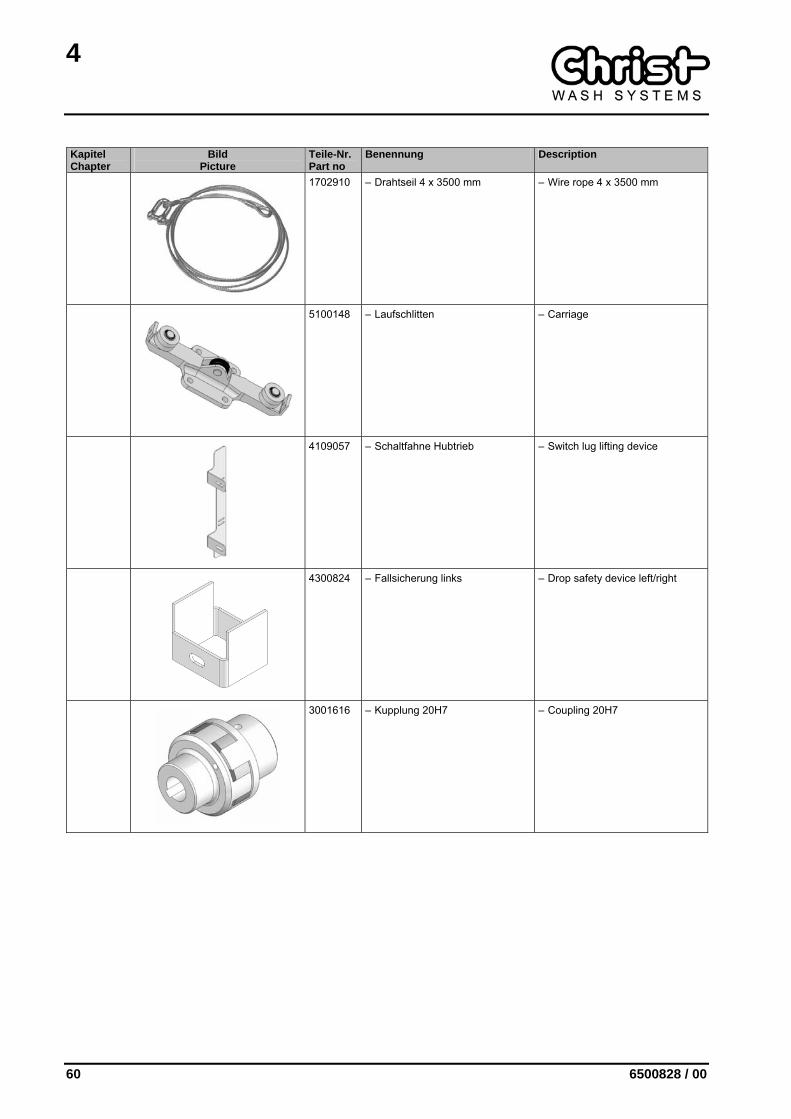
1702910 – Drahtseil 4 x 3500 mm – Wire rope 4 x 3500 mm
5100148 – Laufschlitten – Carriage
4109057 – Schaltfahne Hubtrieb – Switch lug lifting device
4300824 – Fallsicherung links – Drop safety device left/right
3001616 – Kupplung 20H7 – Coupling 20H7
4
6500828 / 00 61
4.3 Dachwalzenrohr Roof cylinder tube
Kapitel Chapter
Bild Picture
Teile-Nr. Part no
Benennung Description
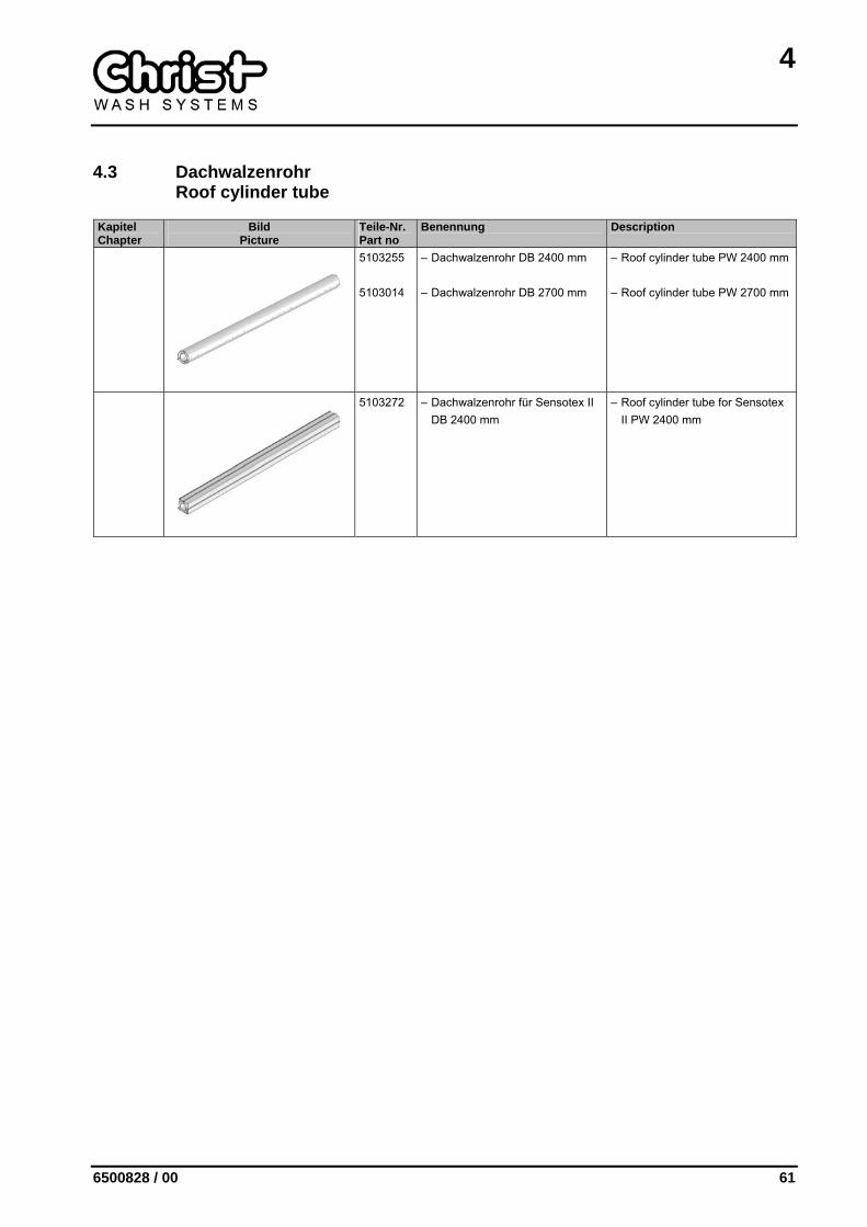
5103255 5103014
– Dachwalzenrohr DB 2400 mm
– Dachwalzenrohr DB 2700 mm
– Roof cylinder tube PW 2400 mm
– Roof cylinder tube PW 2700 mm
5103272 – Dachwalzenrohr für Sensotex II DB 2400 mm
– Roof cylinder tube for Sensotex II PW 2400 mm

4
62 6500828 / 00
4.4 Bürsten-Ausstattung Brush equipment
Kapitel Chapter
Bild Picture
Teile-Nr. Part no
Benennung Description
1730300 1730400 1730500 1730600 1730700 1731000 1731100 1730601 1730401 1730301 1730602 1730302
Borstenvollschale 300 x 400 mm
Blau Rot Gelb Grün Schwarz Weiss Orange Hellgrün Pink Hellblau Lichtgrün Dunkelblau
Brush full shell 300 x 400 mm
Blue Red Yellow Green Black White Orange Light green Pink Light blue Light green Dark blue
1732300 1732100 1732700 1732500 1732600 1732400 1732200 1732501 1732101 1732301 1732502 1732302
Borstenvollschale 300 x 400 mm dop-pelter Besatz
Blau Rot Gelb Grün Schwarz Weiss Orange Hellgrün Pink Hellblau Lichtgrün Dunkelblau
Brush full shell 300 x 400 mm dou-ble trimming
Blue Red Yellow Green Black White Orange Light green Pink Light blue Light green Dark blue
1730001 1730000 1730002 1730003 1730004 1730005 1730006 1730007 1730010 1730011 1730012 1730013
Borstenvollschale 150 x 400 mm
Blau Rot Gelb Grün Schwarz Weiss Orange Hellgrün Pink Hellblau Lichtgrün Dunkelblau
Brush full shell 150 x 400 mm
Blue Red Yellow Green Black White Orange Light green Pink Light blue Light green Dark blue
4
6500828 / 00 63
4.5 Sensotex II-Ausstattung Sensotex II equipment
Kapitel Chapter
Bild Picture
Teile-Nr. Part no
Benennung Description
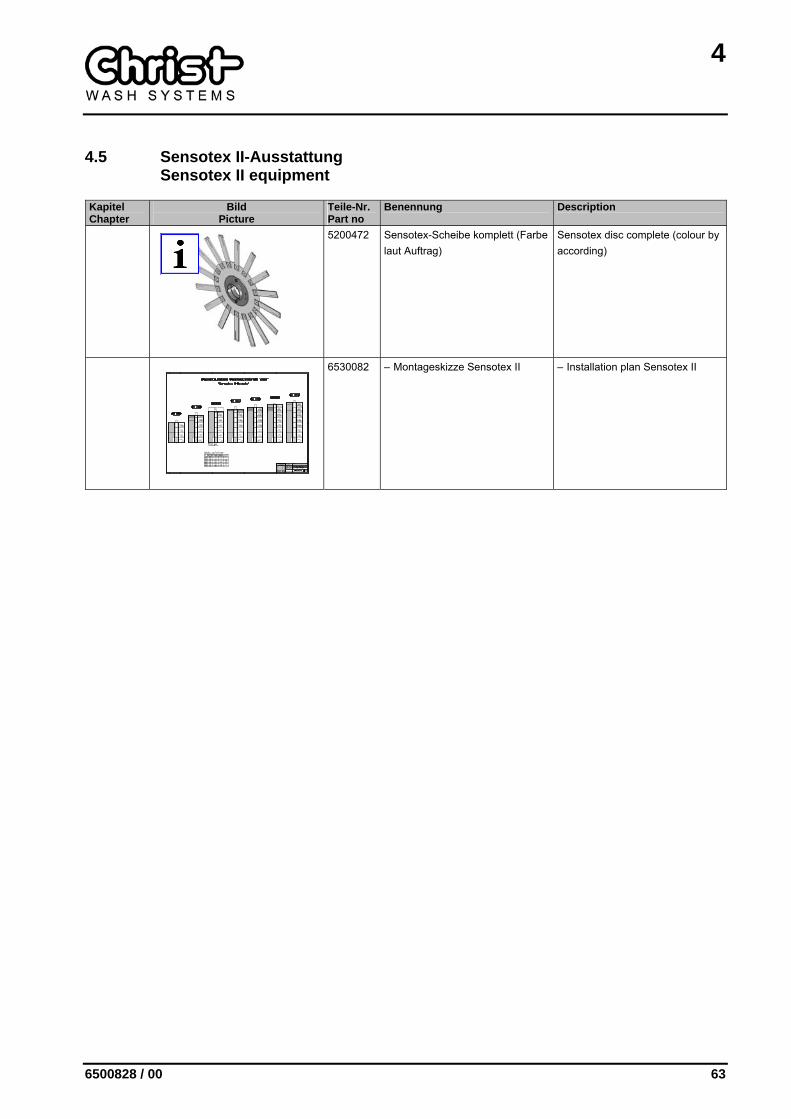
5200472 Sensotex-Scheibe komplett (Farbe laut Auftrag)
Sensotex disc complete (colour by according)
6530082 – Montageskizze Sensotex II – Installation plan Sensotex II

4
64 6500828 / 00
4.6 Sensofil I-Ausstattung Sensofil I equipment
Kapitel Chapter
Bild Picture
Teile-Nr. Part no
Benennung Description
Sensofil I-Ausstattung Sensofil I equipment
1737500 1737501 1737502 1737510 1737520 1737530 1737531 1737550 1737551
– Sensofil I-Element 135 x Ø 890 mm 2x12 Flügel spiralf. Code 6 blau stahlblau violett rot gelb grün hellgrün schwarz hellgrau
– Sensofil I element 135 x Ø 890 mm 2x12 wings spiral Code 6 blue steel blue violett red yellow green light-green black light-grey
5
6500828 / 00 65
5 TROCKNUNGSSYSTEM DRYING SYSTEM
Kapitel Chapter
Bild Picture
Teile-Nr. Part no
Benennung Description
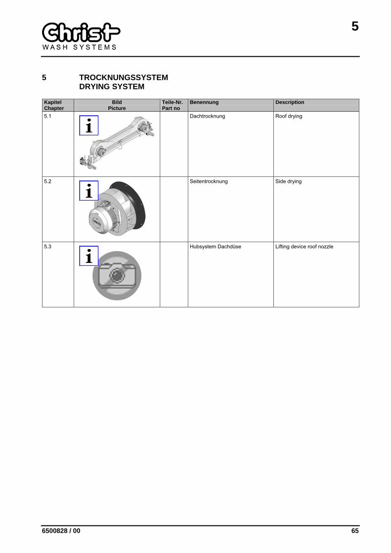
5.1
Dachtrocknung Roof drying
5.2
Seitentrocknung Side drying
5.3
Hubsystem Dachdüse Lifting device roof nozzle
5
66 6500828 / 00
5.1 Dachtrocknung Roof drying
Kapitel Chapter
Bild Picture
Teile-Nr. Part no
Benennung Description
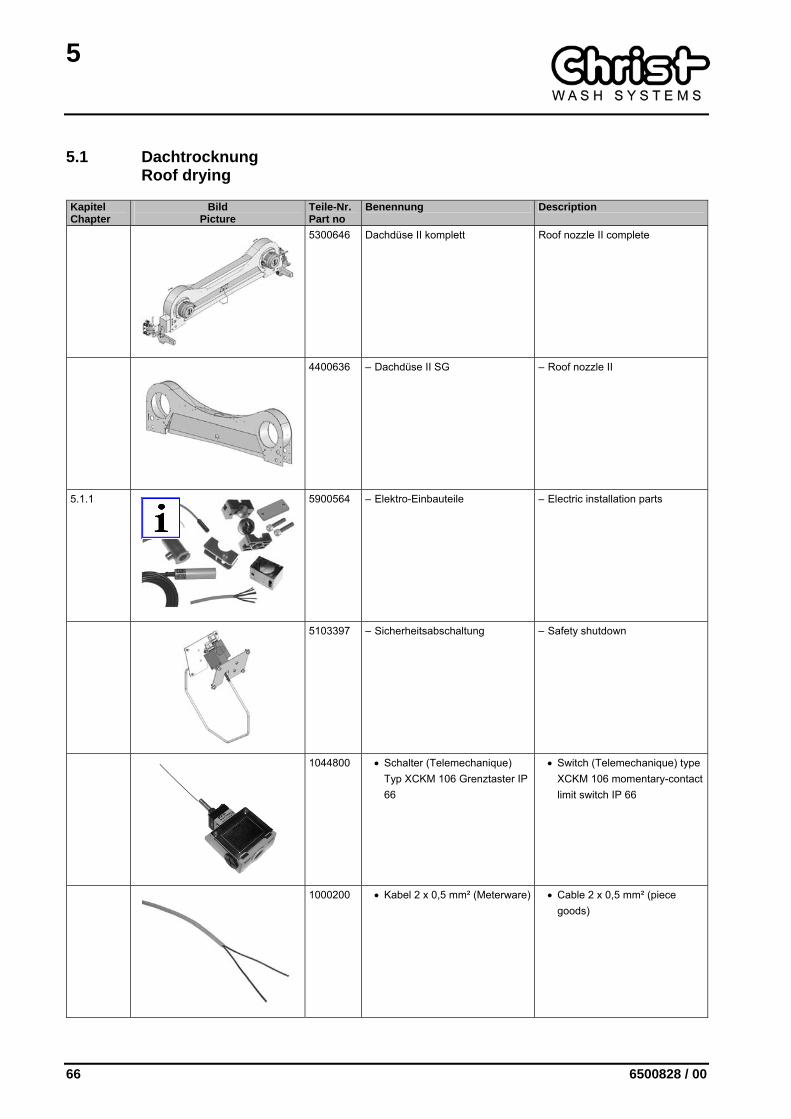
5300646 Dachdüse II komplett Roof nozzle II complete
4400636 – Dachdüse II SG – Roof nozzle II
5.1.1
5900564 – Elektro-Einbauteile – Electric installation parts
5103397 – Sicherheitsabschaltung – Safety shutdown
1044800 • Schalter (Telemechanique) Typ XCKM 106 Grenztaster IP 66
• Switch (Telemechanique) type XCKM 106 momentary-contact limit switch IP 66
1000200 • Kabel 2 x 0,5 mm² (Meterware) • Cable 2 x 0,5 mm² (piece goods)

5
6500828 / 00 67
Kapitel Chapter
Bild Picture
Teile-Nr. Part no
Benennung Description
3500676 • Schaltstab • Switch stick
4107689 – Dachdüsenhalter rechts – Roof nozzle holder right
4107690 – Dachdüsenhalter links – Roof nozzle holder left
5000393 – Schwenkantrieb Dachdüse – Swivelling drive horizontal nozzle
5.1.2
5102634 – Laufschlitteneinheit rechts – Carriage unit right
5101676 – Aufnahme komplett – Locator complete

5
68 6500828 / 00
Kapitel Chapter
Bild Picture
Teile-Nr. Part no
Benennung Description
5.1.3
5102635 – Laufschlitteneinheit links – Carriage unit left
5000259 – OC-Motor, 3 kW, 400 V, 50 Hz 2850 1/min
– OC-motor 3 kW, 400 V, 50 Hz 2850 1/min
1707012 – Ventilatorrad linksdrehend 240 x 102 mm
– Fan impeller left turning 240 x 102 mm
1707011 – Ventilatorrad rechtsdrehend 240 x 102 mm
– Fan impeller right turning 240 x 102 mm
1709610 – Einlaufzarge – Edge ring
1709710 – Schutzgitter Ø 268 mm – Protection grid Ø 268 mm
5
6500828 / 00 69
Kapitel Chapter
Bild Picture
Teile-Nr. Part no
Benennung Description
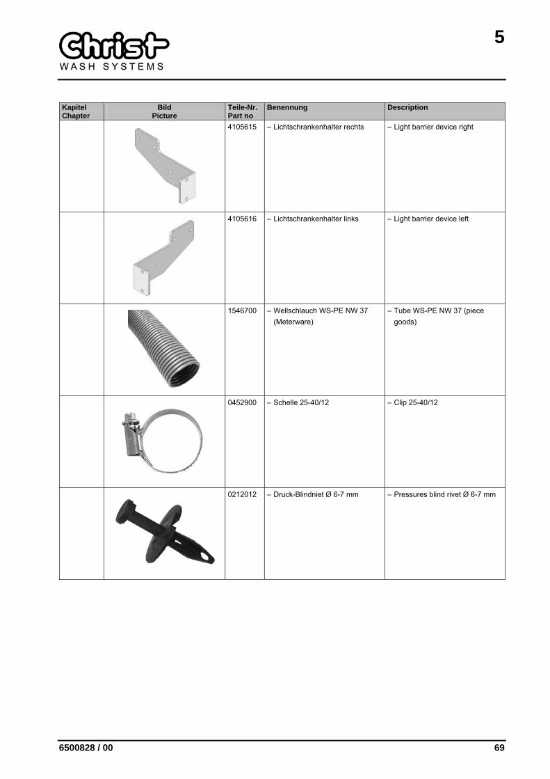
4105615 – Lichtschrankenhalter rechts – Light barrier device right
4105616 – Lichtschrankenhalter links – Light barrier device left
1546700 – Wellschlauch WS-PE NW 37 (Meterware)
– Tube WS-PE NW 37 (piece goods)
0452900 – Schelle 25-40/12 – Clip 25-40/12
0212012 – Druck-Blindniet Ø 6-7 mm – Pressures blind rivet Ø 6-7 mm

5
70 6500828 / 00
5.1.1 Elektro-Einbauteile Electric installation parts
Kapitel Chapter
Bild Picture
Teile-Nr. Part no
Benennung Description
5900564 Elektro-Einbauteile Electric installation parts
1100619 – Lichtschranke TLT-5-5-06 Sen-der 5m Kabel
– Light barrier TLT-5-5-06 emitter 5m cable
1100621 – Lichtschranke TLR-3-5-06 Emp-fänger 5m Kabel
– Light barrier TLR-3-5-06 Re-ceiver 5m cable
1100603 – Lichtschrankenhalterung HMO, Kugelkopf
– Light barrier device support, ball head
1500112 – Lichtschrankenabdeckung – Light barrier covering
1040211 – Näherungsschalter IN-3004-APKG 10-36V DC induktiv Öff-ner 10m Kabel
– Proximity switch IN-3004-APKG 10-36V DC inductive opener 10m Cable
5
6500828 / 00 71
Kapitel Chapter
Bild Picture
Teile-Nr. Part no
Benennung Description
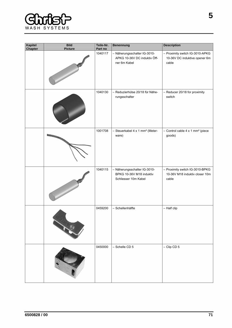
1040117 – Näherungsschalter IG-3010-APKG 10-36V DC induktiv Öff-ner 6m Kabel
– Proximity switch IG-3010-APKG 10-36V DC induktive opener 6m cable
1040130 – Reduzierhülse 20/18 für Nähe-rungsschalter
– Reducer 20/18 for proximity switch
1001708 – Steuerkabel 4 x 1 mm² (Meter-ware)
– Control cable 4 x 1 mm² (piece goods)
1040115 – Näherungsschalter IG-3010-BPKG 10-36V M18 induktiv Schliesser 10m Kabel
– Proximity switch IG-3010-BPKG 10-36V M18 induktiv closer 10m cable
0459200 – Schellenhälfte – Half clip
0450000 – Schelle CD 5 – Clip CD 5
5
72 6500828 / 00
Kapitel Chapter
Bild Picture
Teile-Nr. Part no
Benennung Description
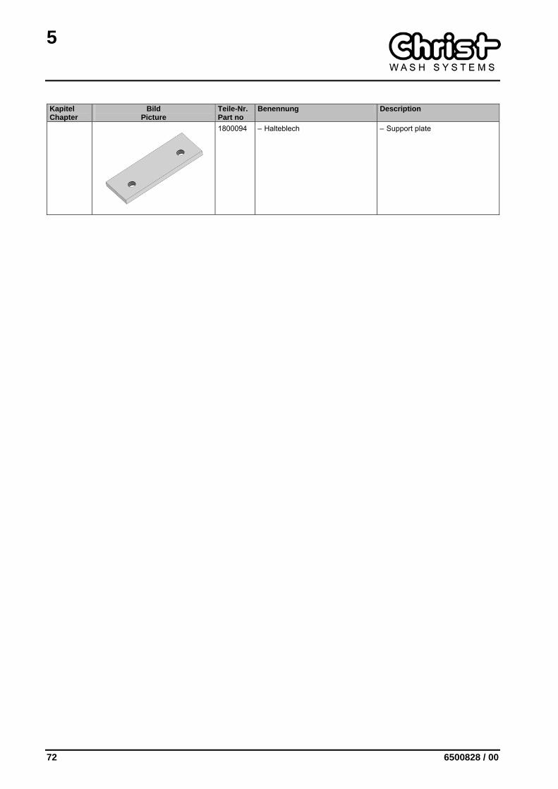
1800094 – Halteblech – Support plate
5
6500828 / 00 73
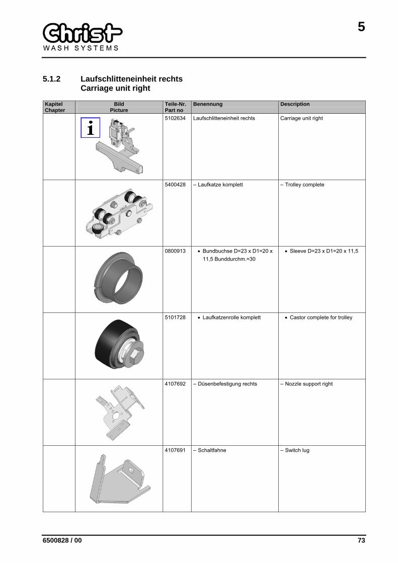
5.1.2 Laufschlitteneinheit rechts Carriage unit right
Kapitel Chapter
Bild Picture
Teile-Nr. Part no
Benennung Description
5102634 Laufschlitteneinheit rechts Carriage unit right
5400428 – Laufkatze komplett – Trolley complete
0800913 • Bundbuchse D=23 x D1=20 x 11,5 Bunddurchm.=30
• Sleeve D=23 x D1=20 x 11,5
5101728 • Laufkatzenrolle komplett • Castor complete for trolley
4107692 – Düsenbefestigung rechts – Nozzle support right
4107691 – Schaltfahne – Switch lug
5
74 6500828 / 00
Kapitel Chapter
Bild Picture
Teile-Nr. Part no
Benennung Description
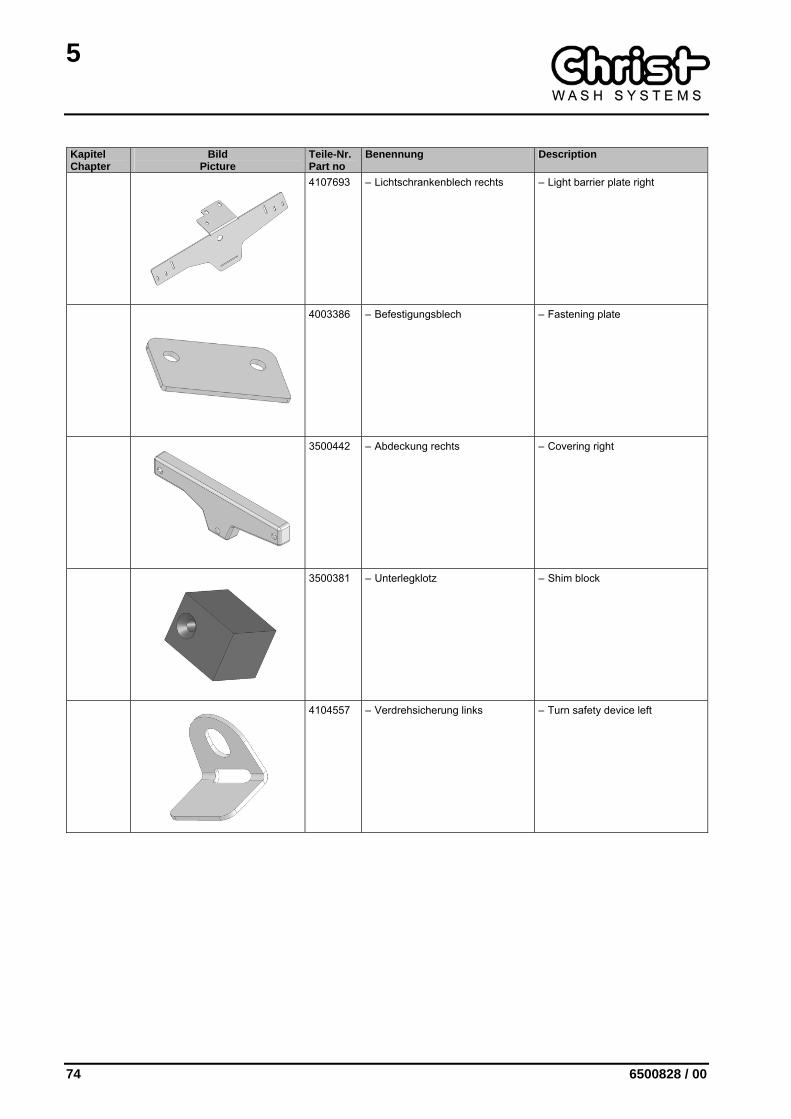
4107693 – Lichtschrankenblech rechts – Light barrier plate right
4003386 – Befestigungsblech – Fastening plate
3500442 – Abdeckung rechts – Covering right
3500381 – Unterlegklotz – Shim block
4104557 – Verdrehsicherung links – Turn safety device left

5
6500828 / 00 75
5.1.3 Laufschlitteneinheit links Carriage unit left
Kapitel Chapter
Bild Picture
Teile-Nr. Part no
Benennung Description
5102635 Laufschlitteneinheit links Carriage unit left
5400428 – Laufkatze komplett – Trolley complete
0800913 • Bundbuchse D=23 x D1=20 x 11,5 Bunddurchm.=30
• Sleeve D=23 x D1=20 x 11,5
5101728 • Laufkatzenrolle komplett • Castor complete for trolley
4303442 – Düsenbefestigung links SG – Nozzle support left
4105611 – Schaltfahne – Switch lug
5
76 6500828 / 00
Kapitel Chapter
Bild Picture
Teile-Nr. Part no
Benennung Description
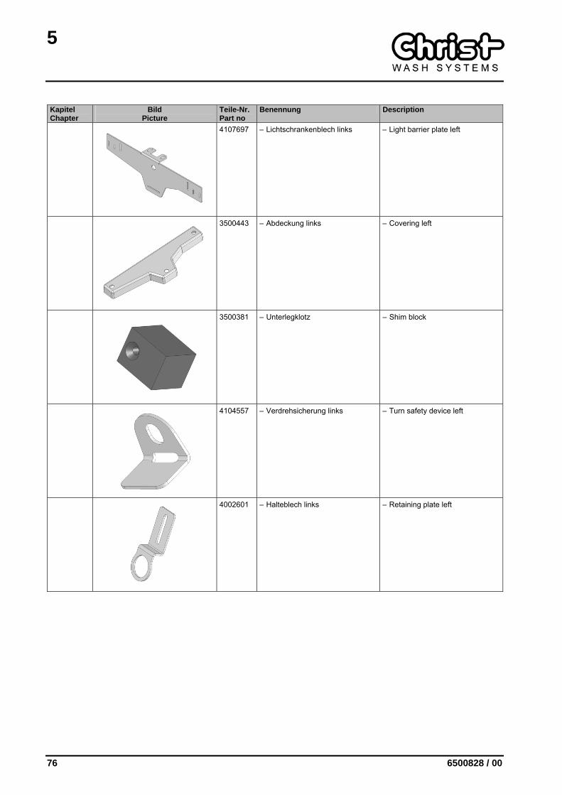
4107697 – Lichtschrankenblech links – Light barrier plate left
3500443 – Abdeckung links – Covering left
3500381 – Unterlegklotz – Shim block
4104557 – Verdrehsicherung links – Turn safety device left
4002601 – Halteblech links – Retaining plate left

5
6500828 / 00 77
5.2 Seitentrocknung Side drying
Kapitel Chapter
Bild Picture
Teile-Nr. Part no
Benennung Description
5300658 5300659 5300657 5300660
Seitentrocknung 4kW (S) DH 2100 Seitentrocknung 4kW (M) DH 2100Seitentrocknung 4kW (S) DH 2300-2900 Seitentrocknung 4kW (M) DH 2300-2900
Side drying 4kW (S) PH 2100 Side drying 4kW (M) PH 2100 Side drying 4kW (S) PH 2300-2900 Side drying 4kW (M) PH 2300-2900
5000389 – OC-Motor, 3,8 kW, 400 V, 50 Hz 2850 1/min
– OC-motor 3,8 kW, 400 V, 50 Hz 2850 1/min
1707710 – Lüfterrad RS-E 400 x 106 rechtsdrehend Info: (M)
– Fan impeller RS-E 400 x 106 clockwise Info: (M)
1707711 – Lüfterrad RS-E 400 x 106 links-drehend Info: (S)
– Fan impeller RS-E 400 x 106 an-ticlockwise Info: (S)
3500660 – Einlaufzarge ES-280 – Edge ring ES-280
0428000 – Ringrosette Ø 5,3 H=3,8 mm – Ring Ø 5,3 H = 3,8 mm
5
78 6500828 / 00
Kapitel Chapter
Bild Picture
Teile-Nr. Part no
Benennung Description
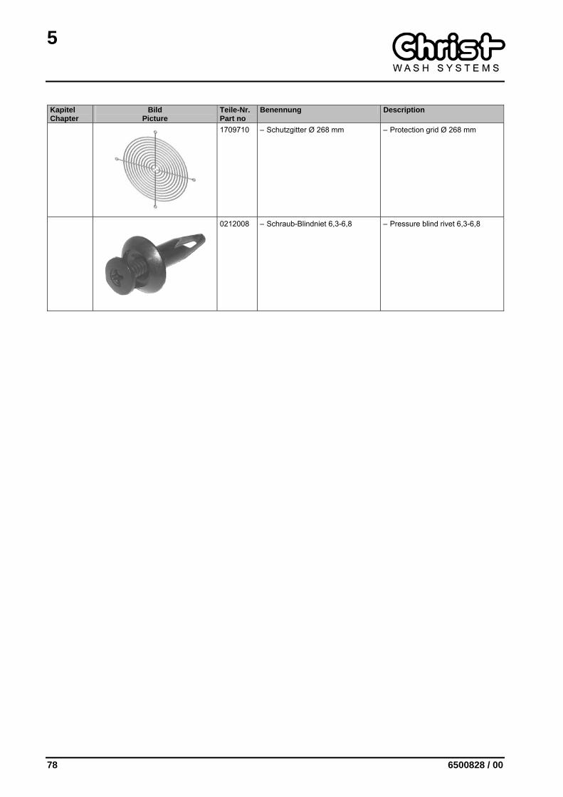
1709710 – Schutzgitter Ø 268 mm – Protection grid Ø 268 mm
0212008 – Schraub-Blindniet 6,3-6,8 – Pressure blind rivet 6,3-6,8
5
6500828 / 00 79
5.3 Hubsystem Dachdüse Lifting device roof nozzle
Kapitel Chapter
Bild Picture
Teile-Nr. Part no
Benennung Description
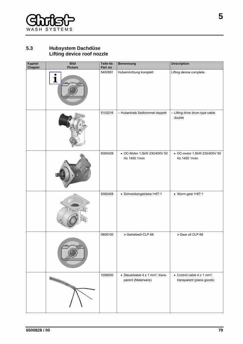
5400891 Hubeinrichtung komplett Lifting device complete
5103216 – Hubantrieb Seiltrommel doppelt – Lifting drive drum-type cable double
5000429 • OC-Motor 1,5kW 230/400V 50 Hz 1450 1/min
• OC-motor 1,5kW 230/400V 50 Hz 1450 1/min
5000458 • Schneckengetriebe I=67:1 • Worm gear I=67:1
0908100 Getriebeöl CLP 68 Gear oil CLP 68
1008000 • Steuerkabel 4 x 1 mm², trans-parent (Meterware)
• Control cable 4 x 1 mm², transparent (piece goods)
5
80 6500828 / 00
Kapitel Chapter
Bild Picture
Teile-Nr. Part no
Benennung Description
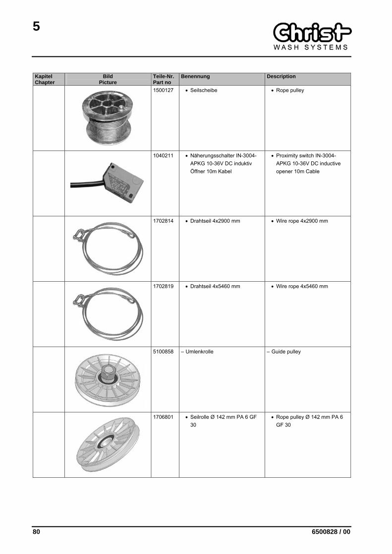
1500127 • Seilscheibe • Rope pulley
1040211 • Näherungsschalter IN-3004-APKG 10-36V DC induktiv Öffner 10m Kabel
• Proximity switch IN-3004-APKG 10-36V DC inductive opener 10m Cable
1702814 • Drahtseil 4x2900 mm • Wire rope 4x2900 mm
1702819 • Drahtseil 4x5460 mm • Wire rope 4x5460 mm
5100858 – Umlenkrolle – Guide pulley
1706801 • Seilrolle Ø 142 mm PA 6 GF 30
• Rope pulley Ø 142 mm PA 6 GF 30
5
6500828 / 00 81
Kapitel Chapter
Bild Picture
Teile-Nr. Part no
Benennung Description
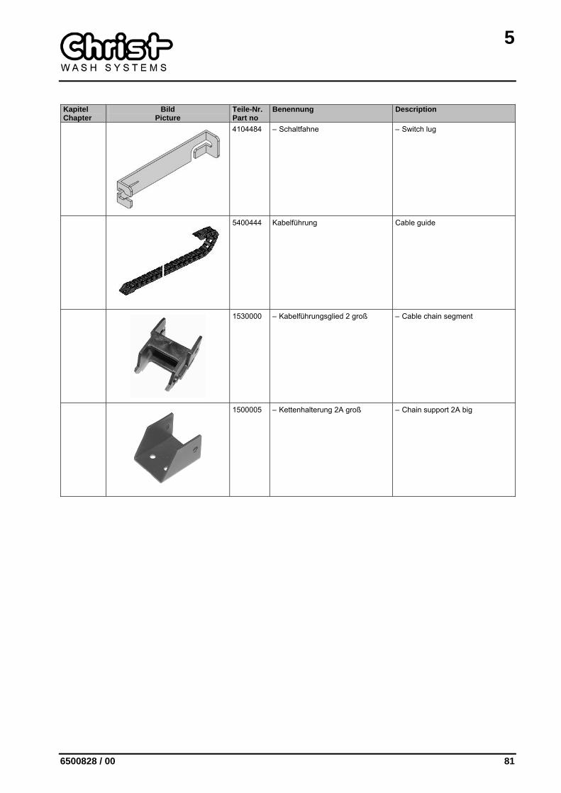
4104484 – Schaltfahne – Switch lug
5400444 Kabelführung Cable guide
1530000 – Kabelführungsglied 2 groß – Cable chain segment
1500005 – Kettenhalterung 2A groß – Chain support 2A big

6
6500828 / 00 83
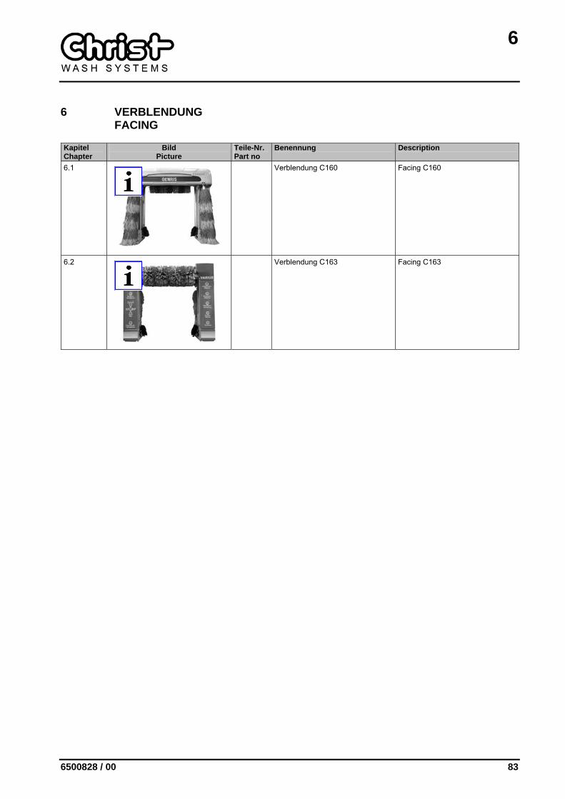
6 VERBLENDUNG FACING
Kapitel Chapter
Bild Picture
Teile-Nr. Part no
Benennung Description
6.1
Verblendung C160 Facing C160
6.2
Verblendung C163 Facing C163
6
84 6500828 / 00
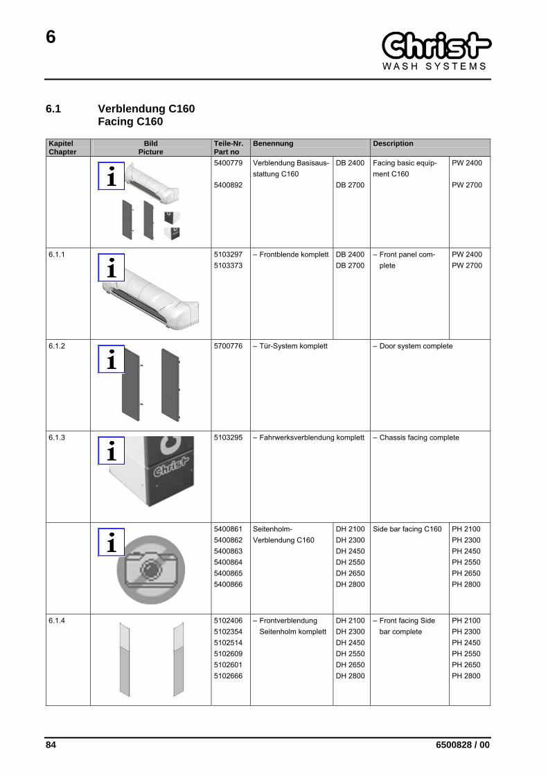
6.1 Verblendung C160 Facing C160
Kapitel Chapter
Bild Picture
Teile-Nr. Part no
Benennung Description
5400779 5400892
Verblendung Basisaus-stattung C160
DB 2400 DB 2700
Facing basic equip-ment C160
PW 2400 PW 2700
6.1.1
5103297 5103373
– Frontblende komplett DB 2400 DB 2700
– Front panel com-plete
PW 2400 PW 2700
6.1.2
5700776 – Tür-System komplett – Door system complete
6.1.3
5103295 – Fahrwerksverblendung komplett – Chassis facing complete
5400861 5400862 5400863 5400864 5400865 5400866
Seitenholm-Verblendung C160
DH 2100 DH 2300 DH 2450 DH 2550 DH 2650 DH 2800
Side bar facing C160 PH 2100 PH 2300 PH 2450 PH 2550 PH 2650 PH 2800
6.1.4
5102406 5102354 5102514 5102609 5102601 5102666
– Frontverblendung Seitenholm komplett
DH 2100 DH 2300 DH 2450 DH 2550 DH 2650 DH 2800
– Front facing Side bar complete
PH 2100 PH 2300 PH 2450 PH 2550 PH 2650 PH 2800
6
6500828 / 00 85
Kapitel Chapter
Bild Picture
Teile-Nr. Part no
Benennung Description
6.1.5
5103338 5103325 5103343 5103346 5103349 5103352
– Heckverblendung Seitenholm komplett
DH 2100 DH 2300 DH 2450 DH 2550 DH 2650 DH 2800
– Rear facing side bar complete
PH 2100 PH 2300 PH 2450 PH 2550 PH 2650 PH 2800
6
86 6500828 / 00
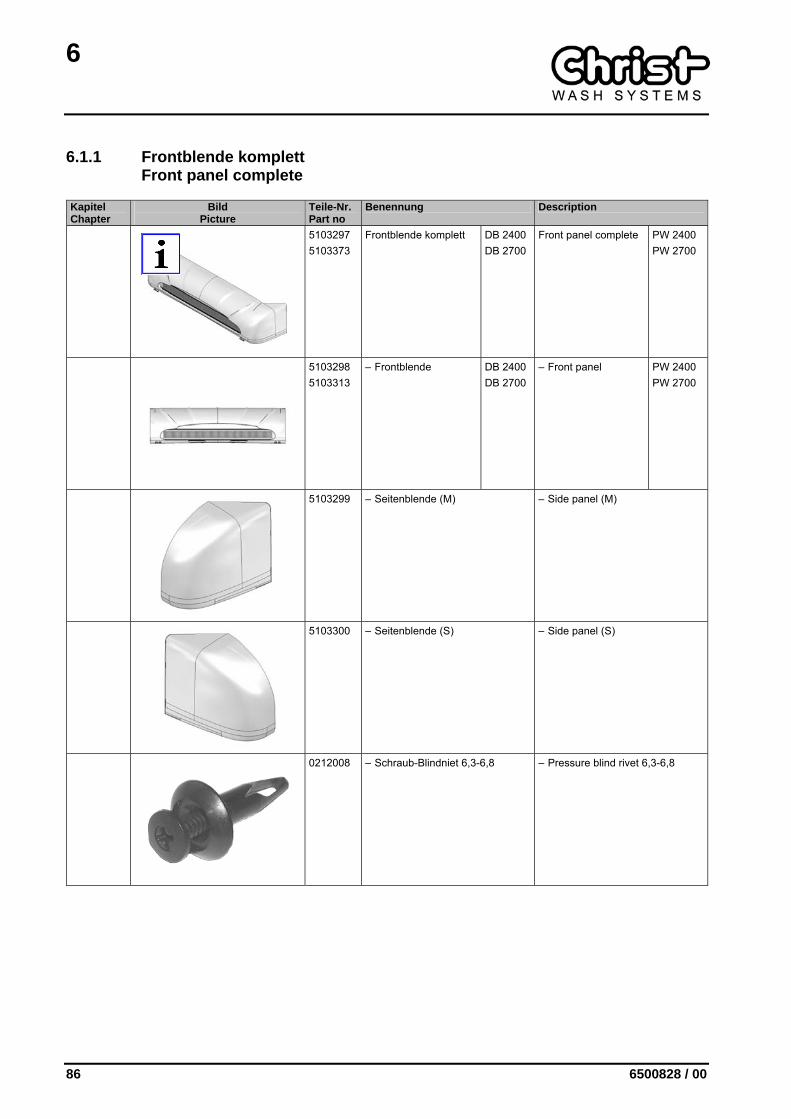
6.1.1 Frontblende komplett Front panel complete
Kapitel Chapter
Bild Picture
Teile-Nr. Part no
Benennung Description
5103297 5103373
Frontblende komplett DB 2400 DB 2700
Front panel complete PW 2400 PW 2700
5103298 5103313
– Frontblende DB 2400 DB 2700
– Front panel PW 2400 PW 2700
5103299 – Seitenblende (M) – Side panel (M)
5103300 – Seitenblende (S) – Side panel (S)
0212008 – Schraub-Blindniet 6,3-6,8 – Pressure blind rivet 6,3-6,8
6
6500828 / 00 87
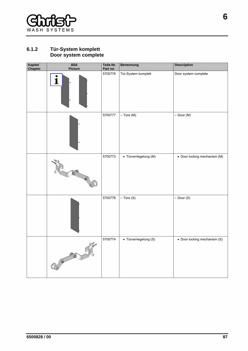
6.1.2 Tür-System komplett Door system complete
Kapitel Chapter
Bild Picture
Teile-Nr. Part no
Benennung Description
5700776 Tür-System komplett Door system complete
5700777 – Türe (M) – Door (M)
5700773 • Türverriegelung (M) • Door locking mechanism (M)
5700778 – Türe (S) – Door (S)
5700774 • Türverriegelung (S) • Door locking mechanism (S)
6
88 6500828 / 00
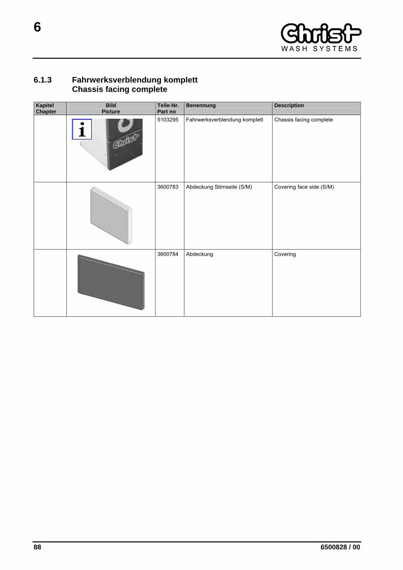
6.1.3 Fahrwerksverblendung komplett Chassis facing complete
Kapitel Chapter
Bild Picture
Teile-Nr. Part no
Benennung Description
5103295 Fahrwerksverblendung komplett Chassis facing complete
3600783 Abdeckung Stirnseite (S/M) Covering face side (S/M)
3600784 Abdeckung Covering
6
6500828 / 00 89
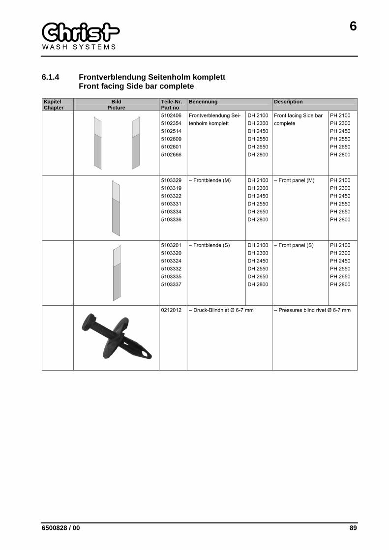
6.1.4 Frontverblendung Seitenholm komplett Front facing Side bar complete
Kapitel Chapter
Bild Picture
Teile-Nr. Part no
Benennung Description
5102406 5102354 5102514 5102609 5102601 5102666
Frontverblendung Sei-tenholm komplett
DH 2100 DH 2300 DH 2450 DH 2550 DH 2650 DH 2800
Front facing Side bar complete
PH 2100 PH 2300 PH 2450 PH 2550 PH 2650 PH 2800
5103329 5103319 5103322 5103331 5103334 5103336
– Frontblende (M) DH 2100 DH 2300 DH 2450 DH 2550 DH 2650 DH 2800
– Front panel (M) PH 2100 PH 2300 PH 2450 PH 2550 PH 2650 PH 2800
5103201 5103320 5103324 5103332 5103335 5103337
– Frontblende (S) DH 2100 DH 2300 DH 2450 DH 2550 DH 2650 DH 2800
– Front panel (S) PH 2100 PH 2300 PH 2450 PH 2550 PH 2650 PH 2800
0212012 – Druck-Blindniet Ø 6-7 mm – Pressures blind rivet Ø 6-7 mm
6
90 6500828 / 00
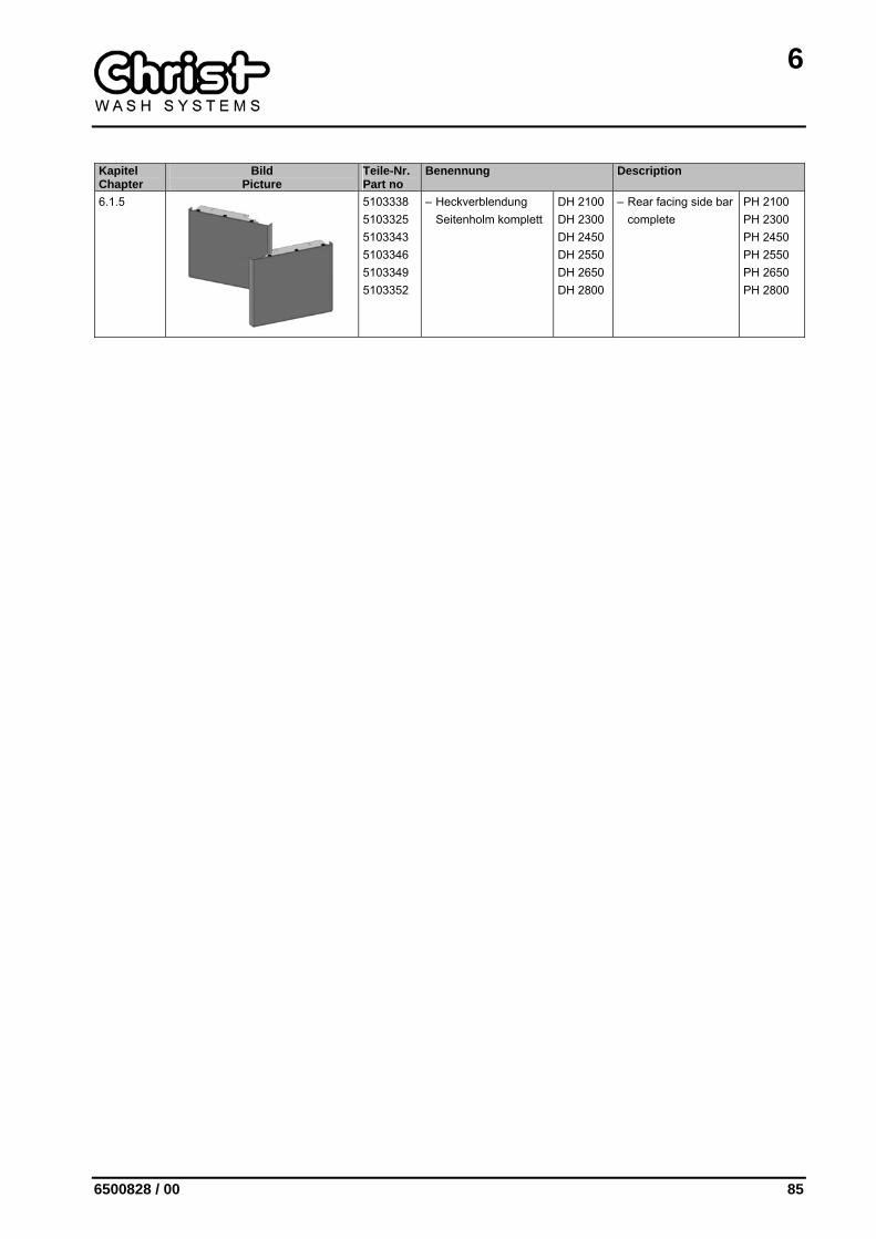
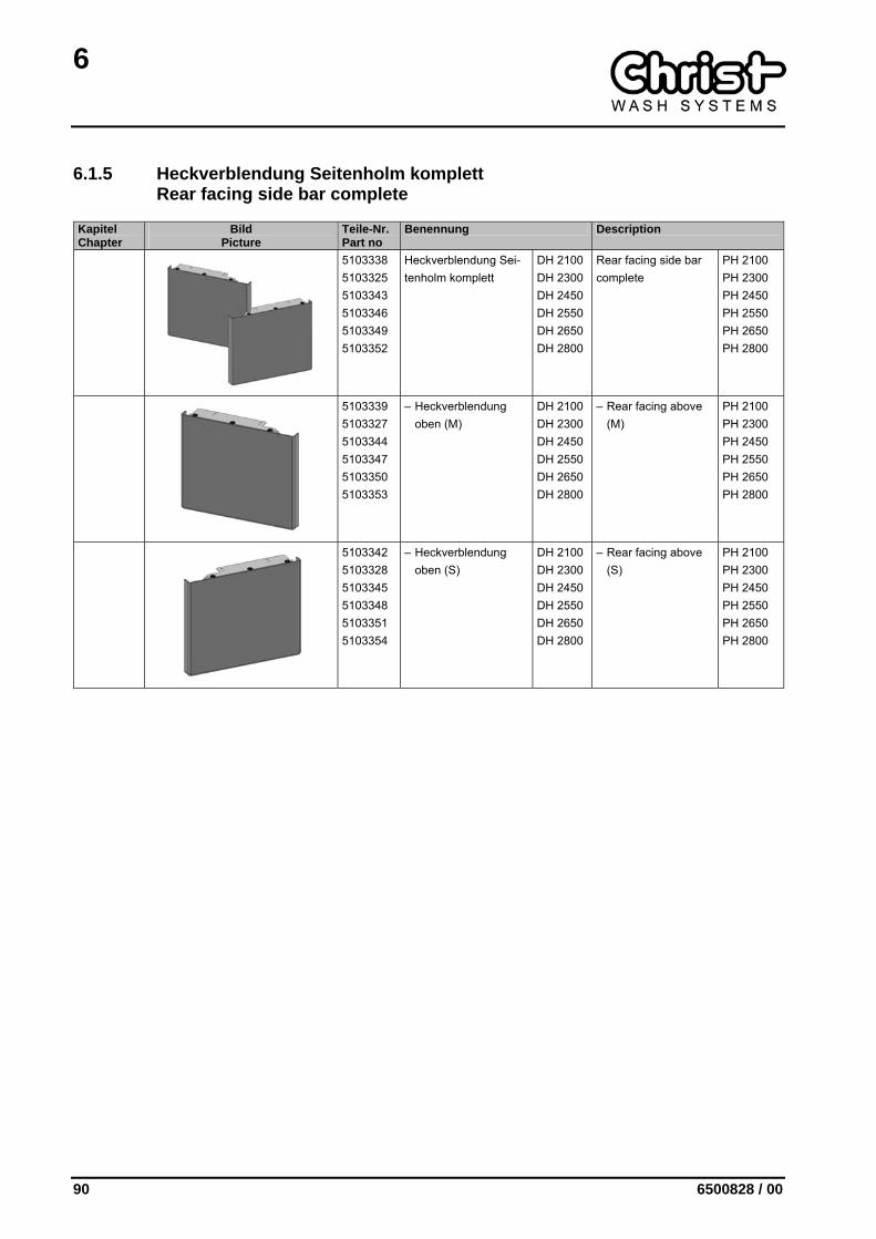
6.1.5 Heckverblendung Seitenholm komplett Rear facing side bar complete
Kapitel Chapter
Bild Picture
Teile-Nr. Part no
Benennung Description
5103338 5103325 5103343 5103346 5103349 5103352
Heckverblendung Sei-tenholm komplett
DH 2100 DH 2300 DH 2450 DH 2550 DH 2650 DH 2800
Rear facing side bar complete
PH 2100 PH 2300 PH 2450 PH 2550 PH 2650 PH 2800
5103339 5103327 5103344 5103347 5103350 5103353
– Heckverblendung oben (M)
DH 2100 DH 2300 DH 2450 DH 2550 DH 2650 DH 2800
– Rear facing above (M)
PH 2100 PH 2300 PH 2450 PH 2550 PH 2650 PH 2800
5103342 5103328 5103345 5103348 5103351 5103354
– Heckverblendung oben (S)
DH 2100 DH 2300 DH 2450 DH 2550 DH 2650 DH 2800
– Rear facing above (S)
PH 2100 PH 2300 PH 2450 PH 2550 PH 2650 PH 2800
6
6500828 / 00 91
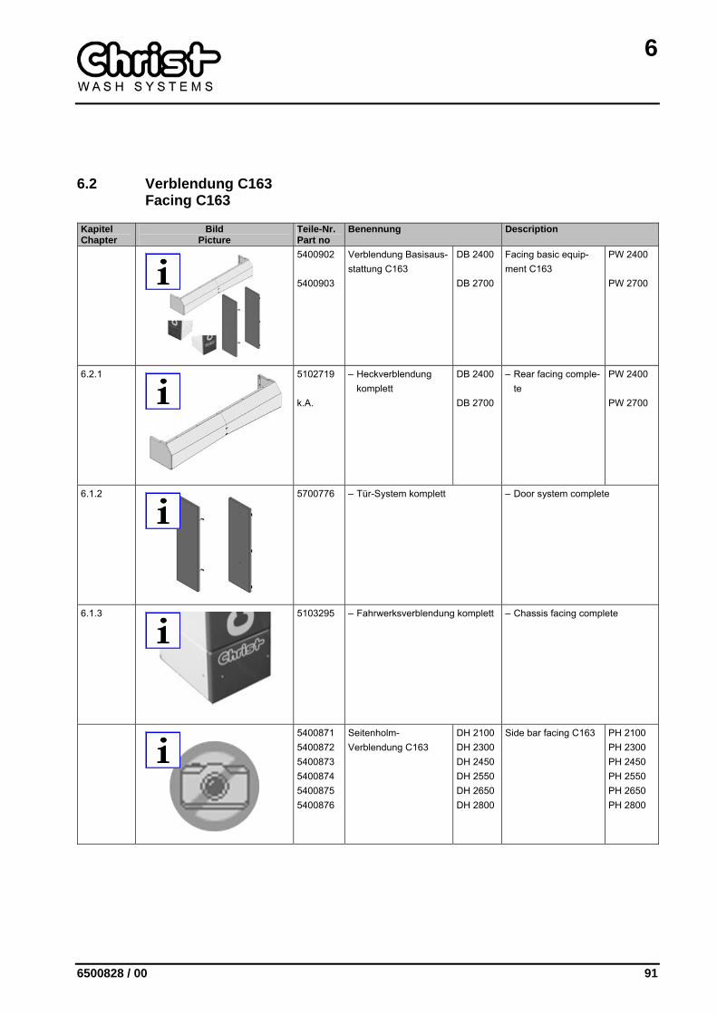
6.2 Verblendung C163
Facing C163
Kapitel Chapter
Bild Picture
Teile-Nr. Part no
Benennung Description
5400902 5400903
Verblendung Basisaus-stattung C163
DB 2400 DB 2700
Facing basic equip-ment C163
PW 2400 PW 2700
6.2.1
5102719 k.A.
– Heckverblendung komplett
DB 2400 DB 2700
– Rear facing comple-te
PW 2400 PW 2700
6.1.2
5700776 – Tür-System komplett – Door system complete
6.1.3
5103295 – Fahrwerksverblendung komplett – Chassis facing complete
5400871 5400872 5400873 5400874 5400875 5400876
Seitenholm-Verblendung C163
DH 2100 DH 2300 DH 2450 DH 2550 DH 2650 DH 2800
Side bar facing C163 PH 2100 PH 2300 PH 2450 PH 2550 PH 2650 PH 2800
6
92 6500828 / 00
Kapitel Chapter
Bild Picture
Teile-Nr. Part no
Benennung Description
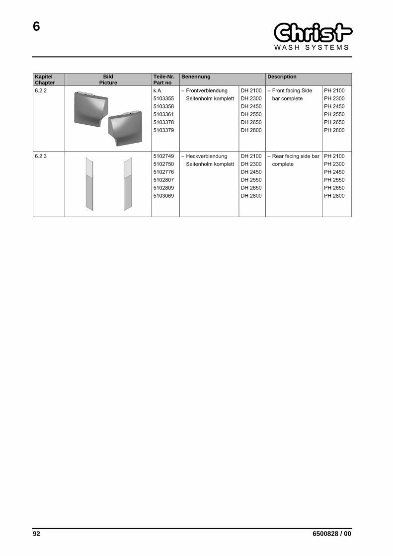
6.2.2
k.A. 5103355 5103358 5103361 5103378 5103379
– Frontverblendung Seitenholm komplett
DH 2100 DH 2300 DH 2450 DH 2550 DH 2650 DH 2800
– Front facing Side bar complete
PH 2100 PH 2300 PH 2450 PH 2550 PH 2650 PH 2800
6.2.3
5102749 5102750 5102776 5102807 5102809 5103069
– Heckverblendung Seitenholm komplett
DH 2100 DH 2300 DH 2450 DH 2550 DH 2650 DH 2800
– Rear facing side bar complete
PH 2100 PH 2300 PH 2450 PH 2550 PH 2650 PH 2800
6
6500828 / 00 93
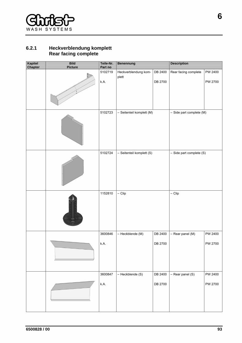
6.2.1 Heckverblendung komplett Rear facing complete
Kapitel Chapter
Bild Picture
Teile-Nr. Part no
Benennung Description
5102719 k.A.
Heckverblendung kom-plett
DB 2400 DB 2700
Rear facing complete PW 2400 PW 2700
5102723 – Seitenteil komplett (M) – Side part complete (M)
5102724 – Seitenteil komplett (S) – Side part complete (S)
1152810 – Clip – Clip
3600846 k.A.
– Heckblende (M) DB 2400 DB 2700
– Rear panel (M) PW 2400 PW 2700
3600847 k.A.
– Heckblende (S) DB 2400 DB 2700
– Rear panel (S) PW 2400 PW 2700
6
94 6500828 / 00
Kapitel Chapter
Bild Picture
Teile-Nr. Part no
Benennung Description
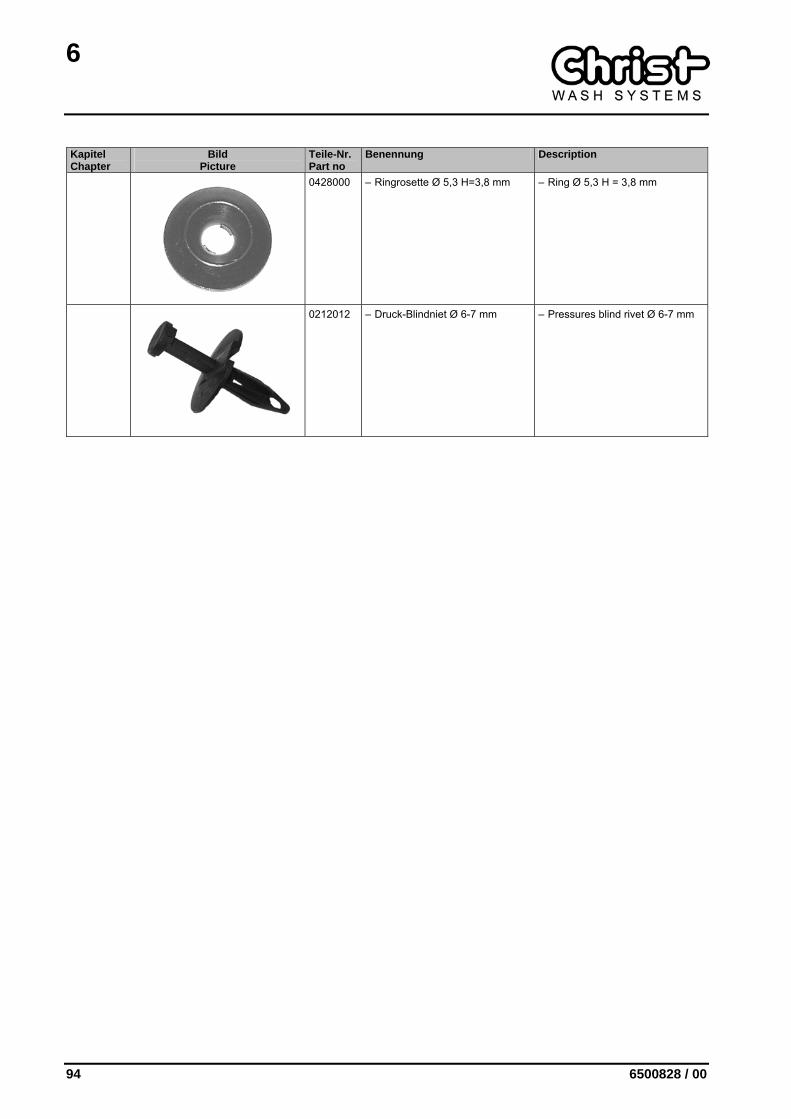
0428000 – Ringrosette Ø 5,3 H=3,8 mm – Ring Ø 5,3 H = 3,8 mm
0212012 – Druck-Blindniet Ø 6-7 mm – Pressures blind rivet Ø 6-7 mm

6
6500828 / 00 95
6.2.2 Frontverblendung Seitenholm komplett Front facing Side bar complete
Kapitel Chapter
Bild Picture
Teile-Nr. Part no
Benennung Description
k.A. 5103355 5103358 5103361 5103378 5103379
Frontverblendung Sei-tenholm komplett
DH 2100 DH 2300 DH 2450 DH 2550 DH 2650 DH 2800
Front facing Side bar complete
PH 2100 PH 2300 PH 2450 PH 2550 PH 2650 PH 2800
k.A. 5103356 5103359 5103362 5103374 5103377
– Frontverblendung oben (M)
DH 2100 DH 2300 DH 2450 DH 2550 DH 2650 DH 2800
– Front facing above (M)
PH 2100 PH 2300 PH 2450 PH 2550 PH 2650 PH 2800
k.A. 5103357 5103360 5103363 5103375 5103376
– Frontverblendung oben (S)
DH 2100 DH 2300 DH 2450 DH 2550 DH 2650 DH 2800
– Front facing above (S)
PH 2100 PH 2300 PH 2450 PH 2550 PH 2650 PH 2800

6
96 6500828 / 00
6.2.3 Heckverblendung Seitenholm komplett Rear facing side bar complete
Kapitel Chapter
Bild Picture
Teile-Nr. Part no
Benennung Description
5102749 5102750 5102776 5102807 5102809 5103069
Heckverblendung Sei-tenholm komplett
DH 2100 DH 2300 DH 2450 DH 2550 DH 2650 DH 2800
Rear facing side bar complete
PH 2100 PH 2300 PH 2450 PH 2550 PH 2650 PH 2800
5103381 5103383 5103385 5103387 5103389 5103391
– Heckblende (M) DH 2100 DH 2300 DH 2450 DH 2550 DH 2650 DH 2800
– Rear panel (M) PH 2100 PH 2300 PH 2450 PH 2550 PH 2650 PH 2800
5103382 5103384 5103386 5103388 5103390 5103392
– Heckblende (S) DH 2100 DH 2300 DH 2450 DH 2550 DH 2650 DH 2800
– Rear panel (S) PH 2100 PH 2300 PH 2450 PH 2550 PH 2650 PH 2800
0212012 – Druck-Blindniet Ø 6-7 mm – Pressures blind rivet Ø 6-7 mm
7
6500828 / 00 97
7 WASSER- UND DOSIERSYSTEM WATER AND DOSING SYSTEM
Kapitel Chapter
Bild Picture
Teile-Nr. Part no
Benennung Description
7.1
Wasser- und Dosiersystem C160 Water and dosing system C160
7.2
Wasser- und Dosiersystem C163 Water and dosing system C163
7
98 6500828 / 00
7.1 Wasser- und Dosiersystem C160 Water and dosing system C160
Kapitel Chapter
Bild Picture
Teile-Nr. Part no
Benennung Description
5802012 5802013 5802014 5802015 5802016 5802017
Wasser- und Dosier-system C160
DH 2100 DH 2300 DH 2450 DH 2550 DH 2650 DH 2800
Water and dosing sys-tem C160
PH 2100 PH 2300 PH 2450 PH 2550 PH 2650 PH 2800
5802163 5802024
– Wasserplatte kom-plett
DH 2100 DH 2300-DH 2800
– Water plate com-plete
PH 2100 PH 2300-PH 2800
7.1.1
5802023 • Frischwasser-Modul • Fresh water module
7.1.2
5801315 – Seitenwalzen-Bewässerung – Side cylinders watering
3300618 3300620 3300622 3300624 3300626 3300628
– Seitensprührohr (M) DH 2100 DH 2300 DH 2450 DH 2550 DH 2650 DH 2800
– Side spraying tube (M)
PH 2100 PH 2300 PH 2450 PH 2550 PH 2650 PH 2800
3300617 3300619 3300621 3300623 3300625 3300627
– Seitensprührohr (S) DH 2100 DH 2300 DH 2450 DH 2550 DH 2650 DH 2800
– Side spraying tube (S)
PH 2100 PH 2300 PH 2450 PH 2550 PH 2650 PH 2800

7
6500828 / 00 99
Kapitel Chapter
Bild Picture
Teile-Nr. Part no
Benennung Description
7.1.3
5801187 – Schlauchbaum – Tube harness
7.1.4
5801313 – Seitenwalzenbewässerung unten komplett
– Side cylinders watering below complete
1268808 – Winkeleinschraubanschluss Ø 10 - ¼" schwenkbar
– Swivelling screw-in gland elbow Ø 10 - ¼" hinged
7.1.5
5801599 – Frontblenden-Bewässerung komplett Frischwasser
– Front panel watering complete fresh water
5801306 – Heckblendenbewässerung – Rear panel watering
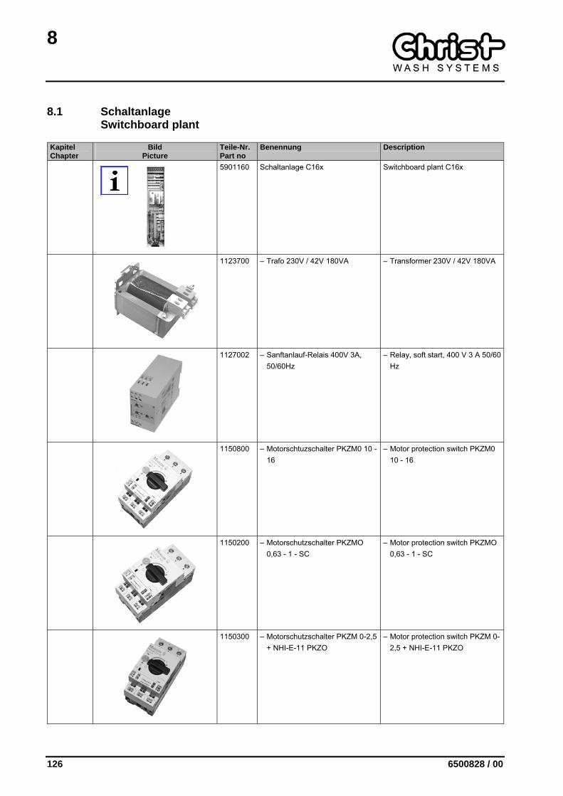
0452300 – Schelle 10-16/9 – Clip 10-16/9
7
100 6500828 / 00
Kapitel Chapter
Bild Picture
Teile-Nr. Part no
Benennung Description
7.1.6
5802011 – Dosiersystem – Dosing system
7
6500828 / 00 101
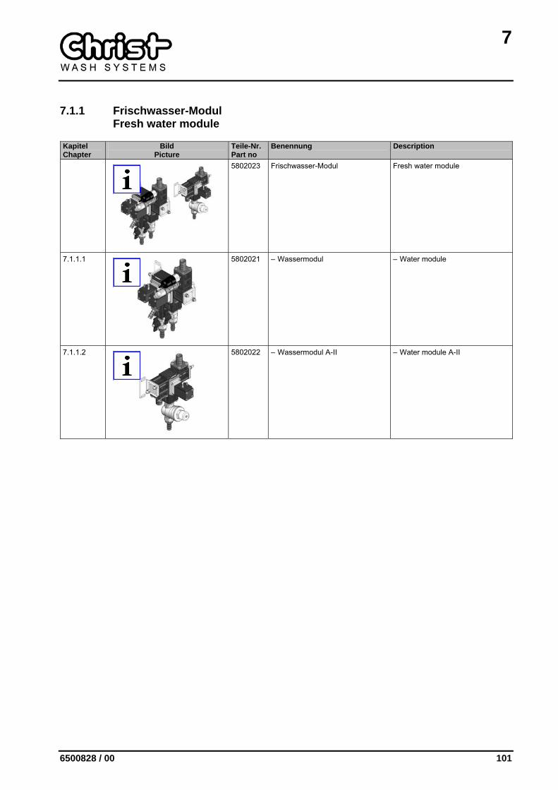
7.1.1 Frischwasser-Modul Fresh water module
Kapitel Chapter
Bild Picture
Teile-Nr. Part no
Benennung Description
5802023 Frischwasser-Modul Fresh water module
7.1.1.1
5802021 – Wassermodul – Water module
7.1.1.2
5802022 – Wassermodul A-II – Water module A-II
7
102 6500828 / 00
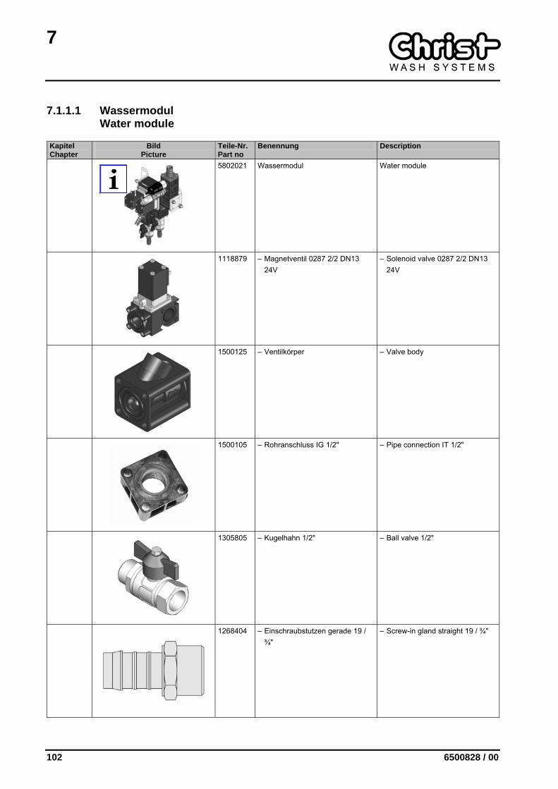
7.1.1.1 Wassermodul Water module
Kapitel Chapter
Bild Picture
Teile-Nr. Part no
Benennung Description
5802021 Wassermodul Water module
1118879 – Magnetventil 0287 2/2 DN13 24V
– Solenoid valve 0287 2/2 DN13 24V
1500125 – Ventilkörper – Valve body
1500105 – Rohranschluss IG 1/2" – Pipe connection IT 1/2"
1305805 – Kugelhahn 1/2" – Ball valve 1/2"
1268404 – Einschraubstutzen gerade 19 / ¾"
– Screw-in gland straight 19 / ¾"
7
6500828 / 00 103
Kapitel Chapter
Bild Picture
Teile-Nr. Part no
Benennung Description
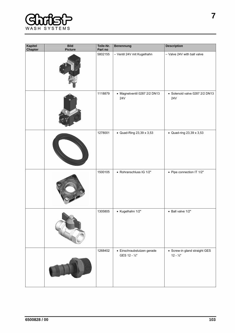
5802155 – Ventil 24V mit Kugelhahn – Valve 24V with ball valve
1118879 • Magnetventil 0287 2/2 DN13 24V
• Solenoid valve 0287 2/2 DN13 24V
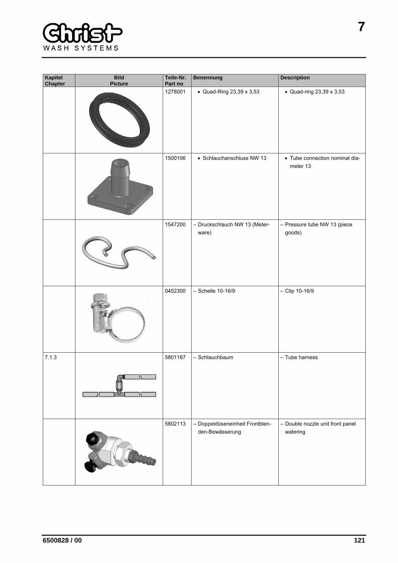
1278001 • Quad-Ring 23,39 x 3,53 • Quad-ring 23,39 x 3,53
1500105 • Rohranschluss IG 1/2" • Pipe connection IT 1/2"
1305805 • Kugelhahn 1/2" • Ball valve 1/2"
1268402 • Einschraubstutzen gerade GES 12 - ½"
• Screw-in gland straight GES 12 - ½"
7
104 6500828 / 00
Kapitel Chapter
Bild Picture
Teile-Nr. Part no
Benennung Description
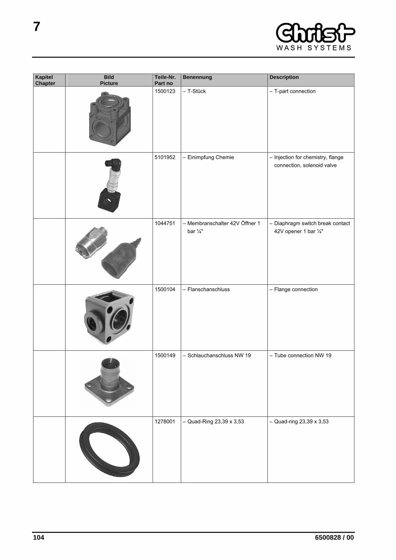
1500123 – T-Stück – T-part connection
5101952 – Einimpfung Chemie – Injection for chemistry, flange connection, solenoid valve
1044751 – Membranschalter 42V Öffner 1 bar ¼"
– Diaphragm switch break contact 42V opener 1 bar ¼"
1500104 – Flanschanschluss – Flange connection
1500149 – Schlauchanschluss NW 19 – Tube connection NW 19
1278001 – Quad-Ring 23,39 x 3,53 – Quad-ring 23,39 x 3,53

7
6500828 / 00 105
7.1.1.2 Wassermodul A-II Water module A-II
Kapitel Chapter
Bild Picture
Teile-Nr. Part no
Benennung Description
5802022 Wassermodul A-II Water module A-II
1500123 – T-Stück – T-part connection
1500149 – Schlauchanschluss NW 19 – Tube connection NW 19
5802154 – Ventil 24V mit Druckminderer – Valve 24V with pressure reducer
1118879 • Magnetventil 0287 2/2 DN13 24V
• Solenoid valve 0287 2/2 DN13 24V
1278001 • Quad-Ring 23,39 x 3,53 • Quad-ring 23,39 x 3,53

7
106 6500828 / 00
Kapitel Chapter
Bild Picture
Teile-Nr. Part no
Benennung Description
1500105 • Rohranschluss IG 1/2" • Pipe connection IT 1/2"
1301101 • Wasserdruckminderer ½" • Water pressure reducer ½"
1268402 • Einschraubstutzen gerade GES 12 - ½"
• Screw-in gland straight GES 12 - ½"
7
6500828 / 00 107
7.1.2 Seitenwalzen-Bewässerung Side cylinders watering
Kapitel Chapter
Bild Picture
Teile-Nr. Part no
Benennung Description
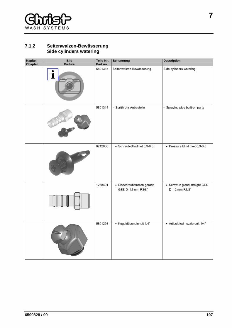
5801315 Seitenwalzen-Bewässerung Side cylinders watering
5801314 – Sprührohr Anbauteile – Spraying pipe built-on parts
0212008 • Schraub-Blindniet 6,3-6,8 • Pressure blind rivet 6,3-6,8
1268401 • Einschraubstutzen gerade GES D=12 mm R3/8"
• Screw-in gland straight GES D=12 mm R3/8"
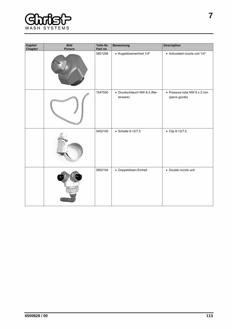
5801298 • Kugeldüseneinheit 1/4" • Articulated nozzle unit 1/4"
7
108 6500828 / 00
7.1.3 Schlauchbaum Tube harness
Kapitel Chapter
Bild Picture
Teile-Nr. Part no
Benennung Description
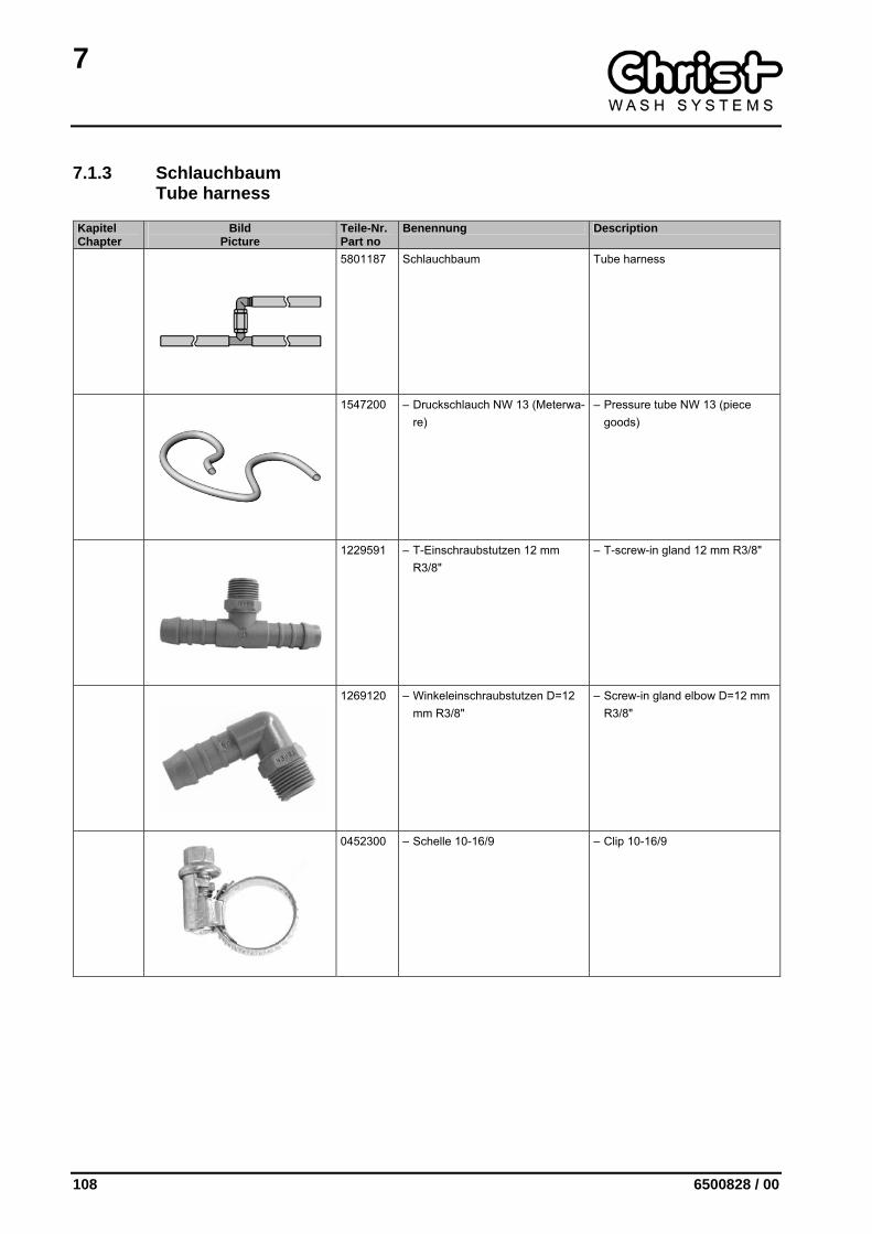
5801187 Schlauchbaum Tube harness
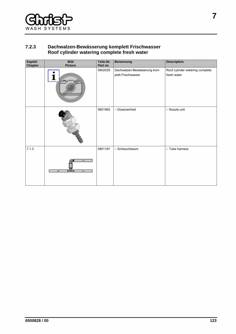
1547200 – Druckschlauch NW 13 (Meterwa-re)
– Pressure tube NW 13 (piece goods)
1229591 – T-Einschraubstutzen 12 mm R3/8"
– T-screw-in gland 12 mm R3/8"
1269120 – Winkeleinschraubstutzen D=12 mm R3/8"
– Screw-in gland elbow D=12 mm R3/8"
0452300 – Schelle 10-16/9 – Clip 10-16/9
7
6500828 / 00 109
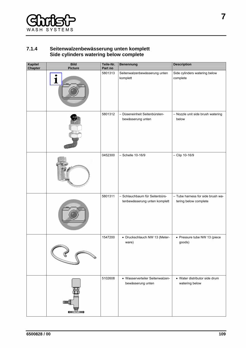
7.1.4 Seitenwalzenbewässerung unten komplett Side cylinders watering below complete
Kapitel Chapter
Bild Picture
Teile-Nr. Part no
Benennung Description
5801313 Seitenwalzenbewässerung unten komplett
Side cylinders watering below complete
5801312 – Düseneinheit Seitenbürsten-bewässerung unten
– Nozzle unit side brush watering below
0452300 – Schelle 10-16/9 – Clip 10-16/9
5801311 – Schlauchbaum für Seitenbürs-tenbewässerung unten komplett
– Tube harness for side brush wa-tering below complete
1547200 • Druckschlauch NW 13 (Meter-ware)
• Pressure tube NW 13 (piece goods)
5102608 • Wasserverteiler Seitenwalzen-bewässerung unten
• Water distributor side drum watering below
7
110 6500828 / 00
Kapitel Chapter
Bild Picture
Teile-Nr. Part no
Benennung Description
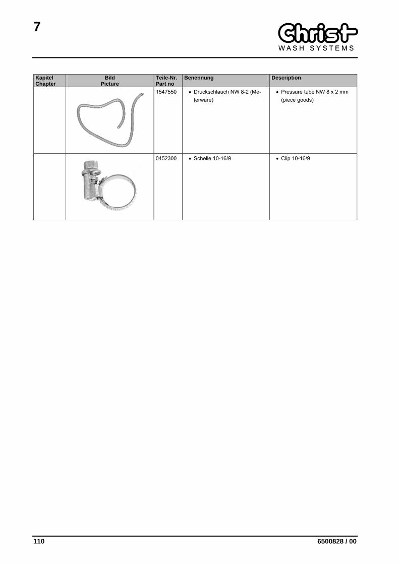
1547550 • Druckschlauch NW 8-2 (Me-terware)
• Pressure tube NW 8 x 2 mm (piece goods)
0452300 • Schelle 10-16/9 • Clip 10-16/9
7
6500828 / 00 111
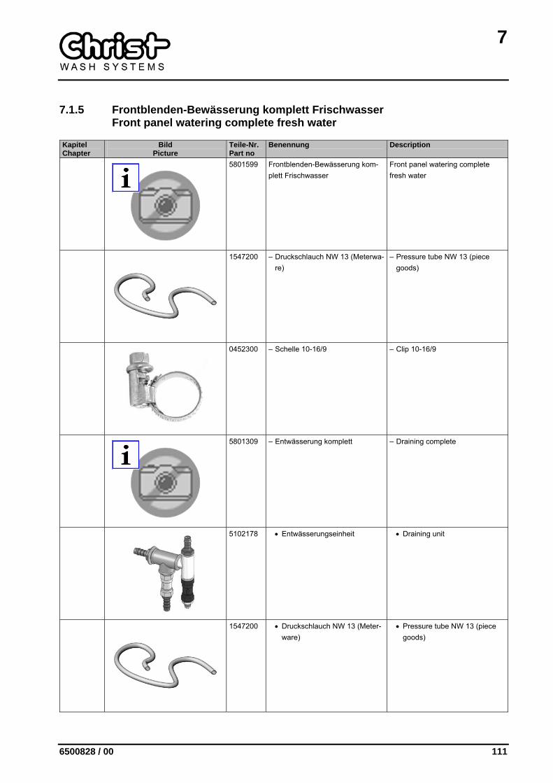
7.1.5 Frontblenden-Bewässerung komplett Frischwasser Front panel watering complete fresh water
Kapitel Chapter
Bild Picture
Teile-Nr. Part no
Benennung Description
5801599 Frontblenden-Bewässerung kom-plett Frischwasser
Front panel watering complete fresh water
1547200 – Druckschlauch NW 13 (Meterwa-re)
– Pressure tube NW 13 (piece goods)
0452300 – Schelle 10-16/9 – Clip 10-16/9
5801309 – Entwässerung komplett – Draining complete
5102178 • Entwässerungseinheit • Draining unit
1547200 • Druckschlauch NW 13 (Meter-ware)
• Pressure tube NW 13 (piece goods)
7
112 6500828 / 00
Kapitel Chapter
Bild Picture
Teile-Nr. Part no
Benennung Description
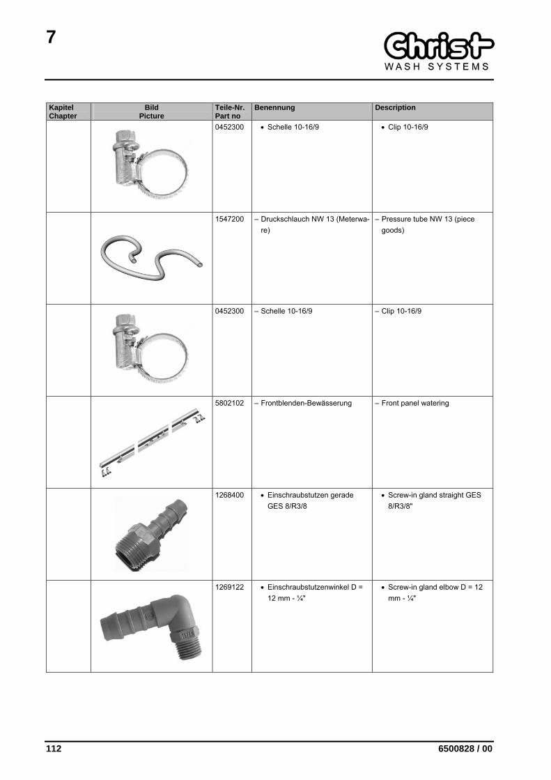
0452300 • Schelle 10-16/9 • Clip 10-16/9
1547200 – Druckschlauch NW 13 (Meterwa-re)
– Pressure tube NW 13 (piece goods)
0452300 – Schelle 10-16/9 – Clip 10-16/9
5802102 – Frontblenden-Bewässerung – Front panel watering
1268400 • Einschraubstutzen gerade GES 8/R3/8
• Screw-in gland straight GES 8/R3/8"
1269122 • Einschraubstutzenwinkel D = 12 mm - ¼"
• Screw-in gland elbow D = 12 mm - ¼"
7
6500828 / 00 113
Kapitel Chapter
Bild Picture
Teile-Nr. Part no
Benennung Description
5801298 • Kugeldüseneinheit 1/4" • Articulated nozzle unit 1/4"
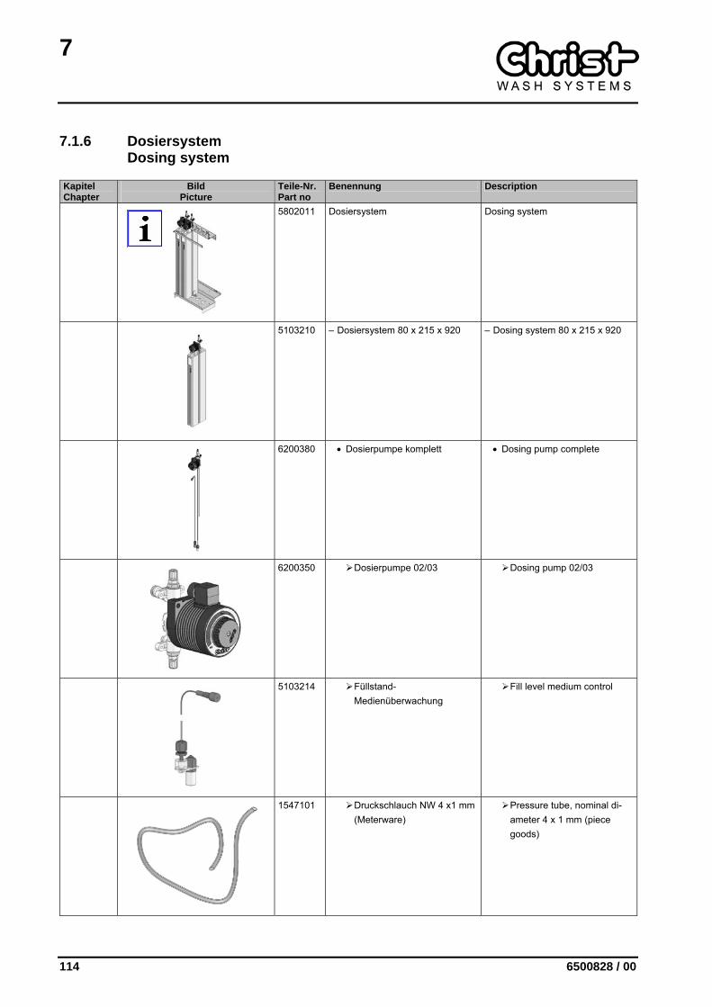
1547550 • Druckschlauch NW 8-2 (Me-terware)
• Pressure tube NW 8 x 2 mm (piece goods)
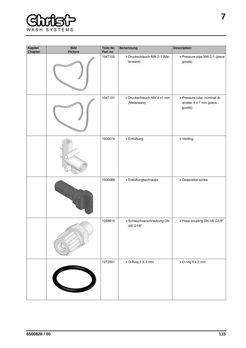
0452100 • Schelle 8-12/7,5 • Clip 8-12/7,5
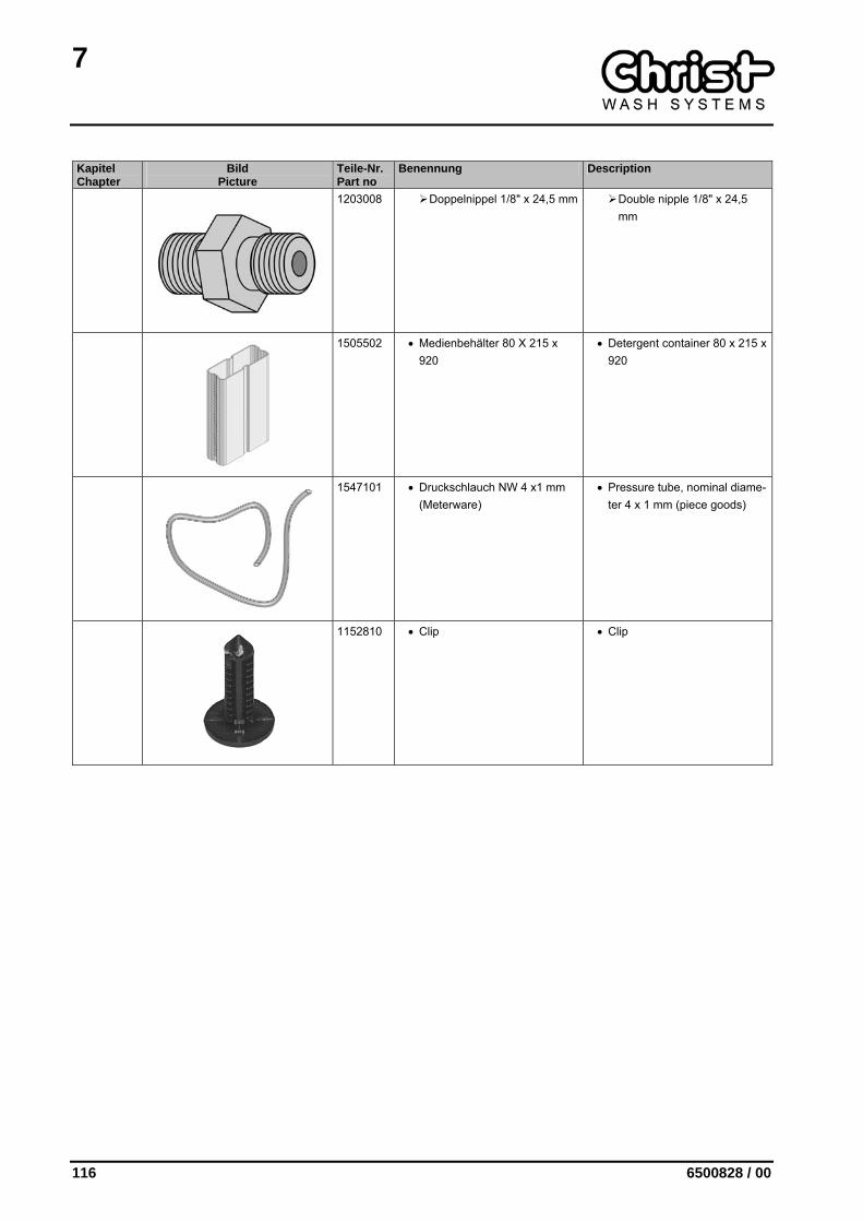
5802104 • Doppeldüsen-Einheit • Double nozzle unit
7
114 6500828 / 00
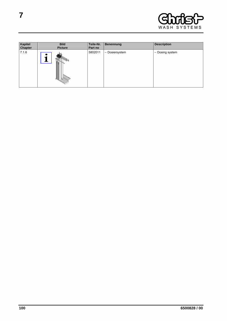
7.1.6 Dosiersystem Dosing system
Kapitel Chapter
Bild Picture
Teile-Nr. Part no
Benennung Description
5802011 Dosiersystem Dosing system
5103210 – Dosiersystem 80 x 215 x 920 – Dosing system 80 x 215 x 920
6200380 • Dosierpumpe komplett • Dosing pump complete
6200350 Dosierpumpe 02/03 Dosing pump 02/03
5103214 Füllstand-Medienüberwachung
Fill level medium control
1547101 Druckschlauch NW 4 x1 mm (Meterware)
Pressure tube, nominal di-ameter 4 x 1 mm (piece goods)
7
6500828 / 00 115
Kapitel Chapter
Bild Picture
Teile-Nr. Part no
Benennung Description
1547105 Druckschlauch NW 2-1 (Me-terware)
Pressure pipe NW 2-1 (piece goods)
1547101 Druckschlauch NW 4 x1 mm (Meterware)
Pressure tube, nominal di-ameter 4 x 1 mm (piece goods)
1500074 Entlüftung Venting
1500088 Entlüftungsschraube Deaeration screw
1268814 Schlauchverschraubung DN 4/6 G1/8"
Hose coupling DN 4/6 G1/8"
1272001 O-Ring 6 X 2 mm O-ring 6 x 2 mm
7
116 6500828 / 00
Kapitel Chapter
Bild Picture
Teile-Nr. Part no
Benennung Description
1203008 Doppelnippel 1/8" x 24,5 mm Double nipple 1/8" x 24,5 mm
1505502 • Medienbehälter 80 X 215 x 920
• Detergent container 80 x 215 x 920
1547101 • Druckschlauch NW 4 x1 mm (Meterware)
• Pressure tube, nominal diame-ter 4 x 1 mm (piece goods)
1152810 • Clip • Clip
7
6500828 / 00 117
7.2 Wasser- und Dosiersystem C163 Water and dosing system C163
Kapitel Chapter
Bild Picture
Teile-Nr. Part no
Benennung Description
5802131 5802132 5802133 5802134 5802135 5802136
Wasser- und Dosier-system C163
DH 2100 DH 2300 DH 2450 DH 2550 DH 2650 DH 2800
Water and dosing sys-tem C163
PH 2100 PH 2300 PH 2450 PH 2550 PH 2650 PH 2800
5802163 5802024
– Wasserplatte kom-plett
DH 2100 DH 2300-DH 2800
– Water plate com-plete
PH 2100 PH 2300-PH 2800
7.1.1
5802023 • Frischwasser-Modul • Fresh water module
7.1.2
5801315 – Seitenwalzen-Bewässerung – Side cylinders watering
3300618 3300620 3300622 3300624 3300626 3300628
– Seitensprührohr (M) DH 2100 DH 2300 DH 2450 DH 2550 DH 2650 DH 2800
– Side spraying tube (M)
PH 2100 PH 2300 PH 2450 PH 2550 PH 2650 PH 2800
3300617 3300619 3300621 3300623 3300625 3300627
– Seitensprührohr (S) DH 2100 DH 2300 DH 2450 DH 2550 DH 2650 DH 2800
– Side spraying tube (S)
PH 2100 PH 2300 PH 2450 PH 2550 PH 2650 PH 2800
7
118 6500828 / 00
Kapitel Chapter
Bild Picture
Teile-Nr. Part no
Benennung Description
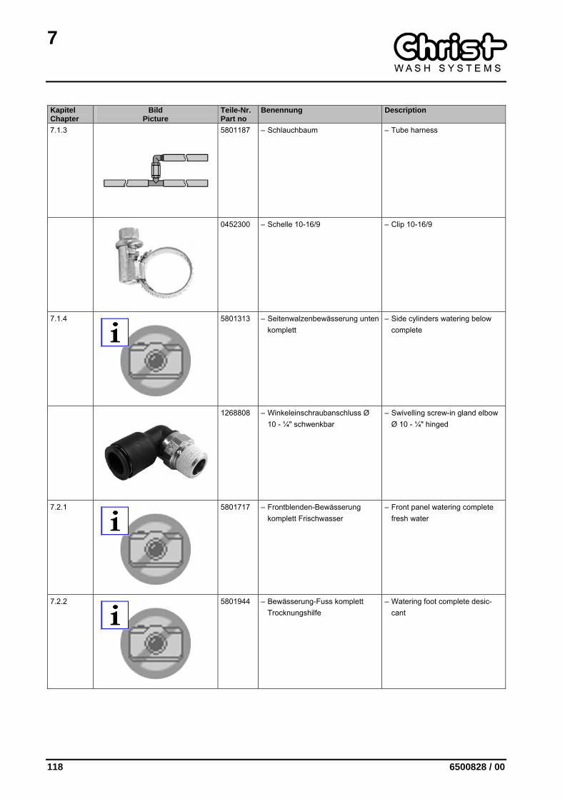
7.1.3
5801187 – Schlauchbaum – Tube harness
0452300 – Schelle 10-16/9 – Clip 10-16/9
7.1.4
5801313 – Seitenwalzenbewässerung unten komplett
– Side cylinders watering below complete
1268808 – Winkeleinschraubanschluss Ø 10 - ¼" schwenkbar
– Swivelling screw-in gland elbow Ø 10 - ¼" hinged
7.2.1
5801717 – Frontblenden-Bewässerung komplett Frischwasser
– Front panel watering complete fresh water
7.2.2
5801944 – Bewässerung-Fuss komplett Trocknungshilfe
– Watering foot complete desic-cant
7
6500828 / 00 119
Kapitel Chapter
Bild Picture
Teile-Nr. Part no
Benennung Description
7.1.6
5802011 – Dosiersystem – Dosing system
7.2.3
5802029 – Dachwalzen-Bewässerung kom-plett Frischwasser
– Roof cylinder watering complete fresh water
7
120 6500828 / 00
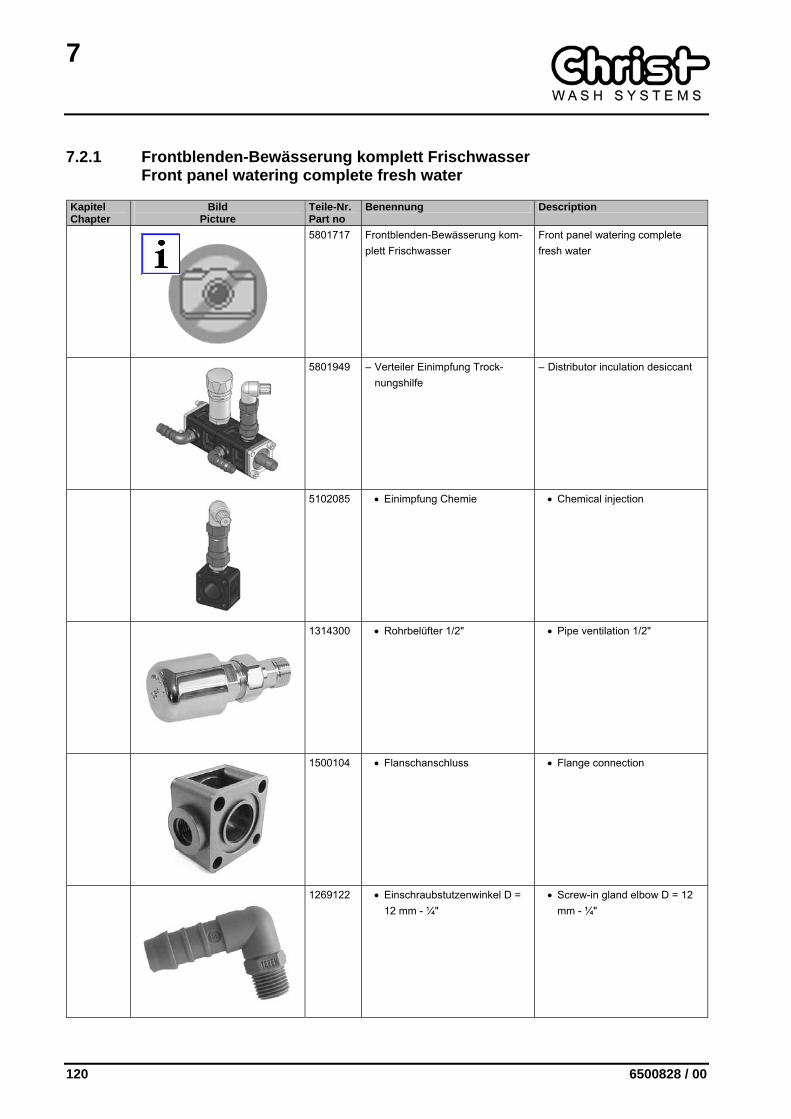
7.2.1 Frontblenden-Bewässerung komplett Frischwasser Front panel watering complete fresh water
Kapitel Chapter
Bild Picture
Teile-Nr. Part no
Benennung Description
5801717 Frontblenden-Bewässerung kom-plett Frischwasser
Front panel watering complete fresh water
5801949 – Verteiler Einimpfung Trock-nungshilfe
– Distributor inculation desiccant
5102085 • Einimpfung Chemie • Chemical injection
1314300 • Rohrbelüfter 1/2" • Pipe ventilation 1/2"
1500104 • Flanschanschluss • Flange connection
1269122 • Einschraubstutzenwinkel D = 12 mm - ¼"
• Screw-in gland elbow D = 12 mm - ¼"
7
6500828 / 00 121
Kapitel Chapter
Bild Picture
Teile-Nr. Part no
Benennung Description
1278001 • Quad-Ring 23,39 x 3,53 • Quad-ring 23,39 x 3,53
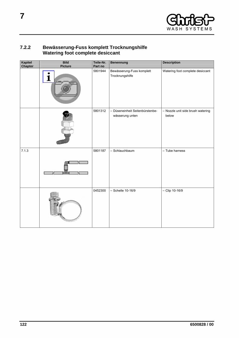
1500106 • Schlauchanschluss NW 13 • Tube connection nominal dia-meter 13
1547200 – Druckschlauch NW 13 (Meter-ware)
– Pressure tube NW 13 (piece goods)
0452300 – Schelle 10-16/9 – Clip 10-16/9
7.1.3
5801187 – Schlauchbaum – Tube harness
5802113 – Doppeldüseneinheit Frontblen-den-Bewässerung
– Double nozzle unit front panel watering
7
122 6500828 / 00
7.2.2 Bewässerung-Fuss komplett Trocknungshilfe Watering foot complete desiccant
Kapitel Chapter
Bild Picture
Teile-Nr. Part no
Benennung Description
5801944 Bewässerung-Fuss komplett Trocknungshilfe
Watering foot complete desiccant
5801312 – Düseneinheit Seitenbürstenbe-wässerung unten
– Nozzle unit side brush watering below
7.1.3
5801187 – Schlauchbaum – Tube harness
0452300 – Schelle 10-16/9 – Clip 10-16/9
7
6500828 / 00 123
7.2.3 Dachwalzen-Bewässerung komplett Frischwasser Roof cylinder watering complete fresh water
Kapitel Chapter
Bild Picture
Teile-Nr. Part no
Benennung Description
5802029 Dachwalzen-Bewässerung kom-plett Frischwasser
Roof cylinder watering complete fresh water
5801962 – Düseneinheit – Nozzle unit
7.1.3
5801187 – Schlauchbaum – Tube harness


8
6500828 / 00 125
8 STEUERUNGSSYSTEM CONTROL SYSTEM
Kapitel Chapter
Bild Picture
Teile-Nr. Part no
Benennung Description
8.1
5901160 Schaltanlage Switchboard plant
8.2
5900514 Elektro-Einbauteile Electric installation parts
8
126 6500828 / 00
8.1 Schaltanlage Switchboard plant
Kapitel Chapter
Bild Picture
Teile-Nr. Part no
Benennung Description
5901160 Schaltanlage C16x Switchboard plant C16x
1123700 – Trafo 230V / 42V 180VA – Transformer 230V / 42V 180VA
1127002 – Sanftanlauf-Relais 400V 3A, 50/60Hz
– Relay, soft start, 400 V 3 A 50/60 Hz
1150800 – Motorschtuzschalter PKZM0 10 - 16
– Motor protection switch PKZM0 10 - 16
1150200 – Motorschutzschalter PKZMO 0,63 - 1 - SC
– Motor protection switch PKZMO 0,63 - 1 - SC
1150300 – Motorschutzschalter PKZM 0-2,5 + NHI-E-11 PKZO
– Motor protection switch PKZM 0-2,5 + NHI-E-11 PKZO
8
6500828 / 00 127
Kapitel Chapter
Bild Picture
Teile-Nr. Part no
Benennung Description
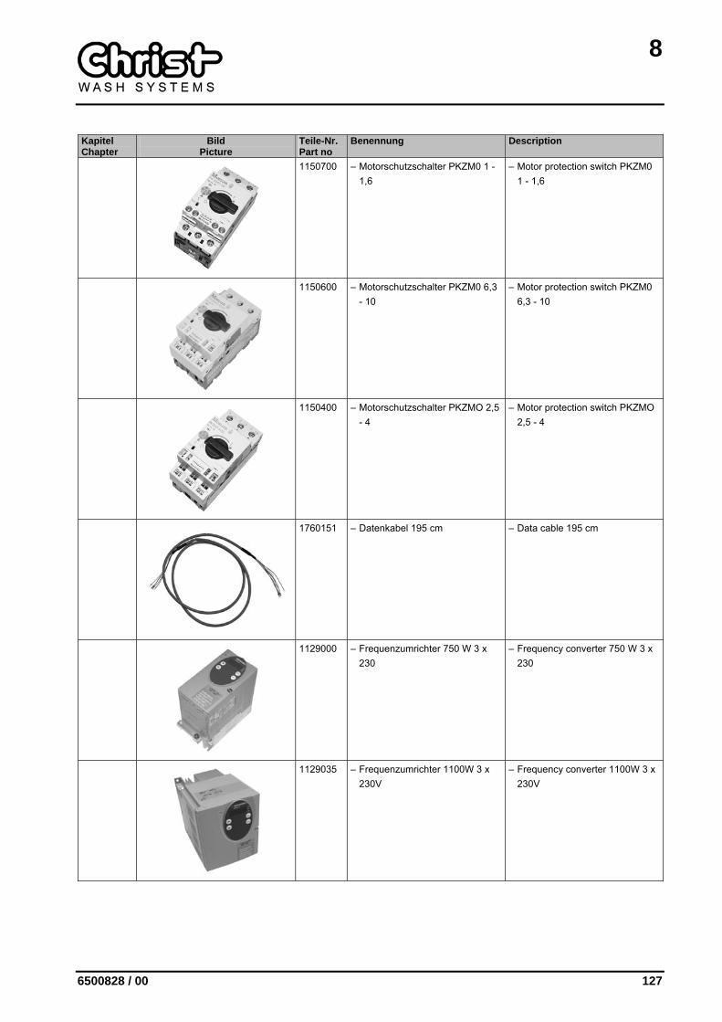
1150700 – Motorschutzschalter PKZM0 1 - 1,6
– Motor protection switch PKZM0 1 - 1,6
1150600 – Motorschutzschalter PKZM0 6,3 - 10
– Motor protection switch PKZM0 6,3 - 10
1150400 – Motorschutzschalter PKZMO 2,5 - 4
– Motor protection switch PKZMO 2,5 - 4
1760151 – Datenkabel 195 cm – Data cable 195 cm
1129000 – Frequenzumrichter 750 W 3 x 230
– Frequency converter 750 W 3 x 230
1129035 – Frequenzumrichter 1100W 3 x 230V
– Frequency converter 1100W 3 x 230V
8
128 6500828 / 00
Kapitel Chapter
Bild Picture
Teile-Nr. Part no
Benennung Description
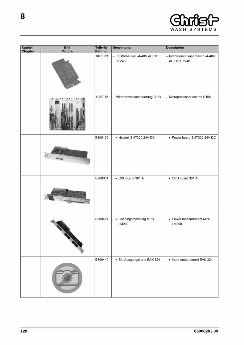
1070003 – Entstörbauteil 24-48V AC/DC PZV48
– Interference suppressor 24-48V AC/DC PZV48
1123012 – Mikroprozessorsteuerung C16x – Microprocessor control C16x
E800130 • Netzteil SNT300 24V DC • Power board SNT300 24V DC
E800001 • CPU-Karte 301 A • CPU board 301 A
E800411 • Leistungsmessung MPS LM200
• Power measurement MPS LM200
E800440 • Ein-Ausgangskarte EAK 324 • Input-output board EAK 324
8
6500828 / 00 129
Kapitel Chapter
Bild Picture
Teile-Nr. Part no
Benennung Description
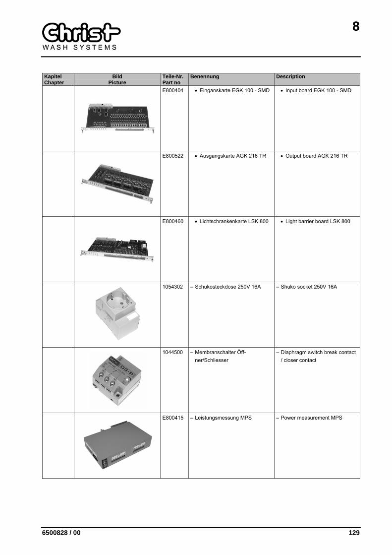
E800404 • Einganskarte EGK 100 - SMD • Input board EGK 100 - SMD
E800522 • Ausgangskarte AGK 216 TR • Output board AGK 216 TR
E800460 • Lichtschrankenkarte LSK 800 • Light barrier board LSK 800
1054302 – Schukosteckdose 250V 16A – Shuko socket 250V 16A
1044500 – Membranschalter Öff-ner/Schliesser
– Diaphragm switch break contact / closer contact
E800415 – Leistungsmessung MPS – Power measurement MPS
8
130 6500828 / 00
Kapitel Chapter
Bild Picture
Teile-Nr. Part no
Benennung Description
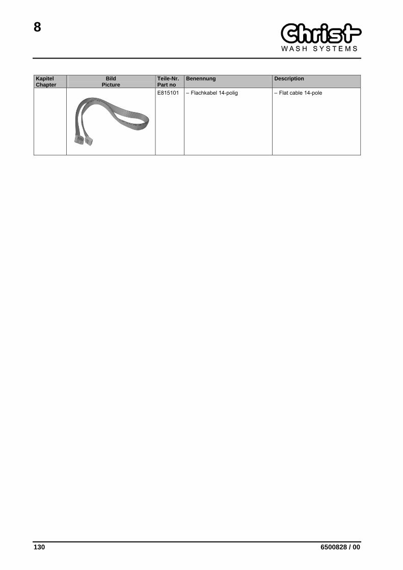
E815101 – Flachkabel 14-polig – Flat cable 14-pole
8
6500828 / 00 131
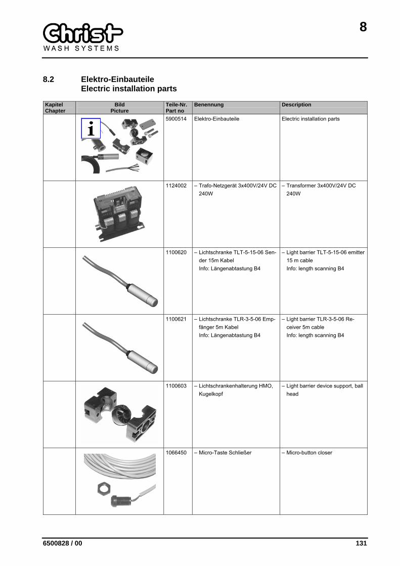
8.2 Elektro-Einbauteile Electric installation parts
Kapitel Chapter
Bild Picture
Teile-Nr. Part no
Benennung Description
5900514 Elektro-Einbauteile Electric installation parts
1124002 – Trafo-Netzgerät 3x400V/24V DC 240W
– Transformer 3x400V/24V DC 240W
1100620 – Lichtschranke TLT-5-15-06 Sen-der 15m Kabel Info: Längenabtastung B4
– Light barrier TLT-5-15-06 emitter 15 m cable Info: length scanning B4
1100621 – Lichtschranke TLR-3-5-06 Emp-fänger 5m Kabel Info: Längenabtastung B4
– Light barrier TLR-3-5-06 Re-ceiver 5m cable Info: length scanning B4
1100603 – Lichtschrankenhalterung HMO, Kugelkopf
– Light barrier device support, ball head
1066450 – Micro-Taste Schließer – Micro-button closer

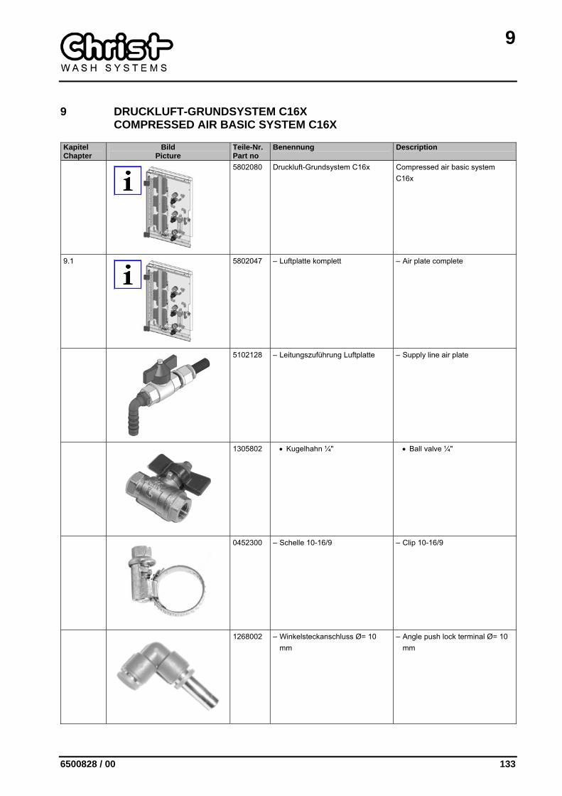
9
6500828 / 00 133
9 DRUCKLUFT-GRUNDSYSTEM C16X COMPRESSED AIR BASIC SYSTEM C16X
Kapitel Chapter
Bild Picture
Teile-Nr. Part no
Benennung Description
5802080 Druckluft-Grundsystem C16x Compressed air basic system C16x
9.1
5802047 – Luftplatte komplett – Air plate complete
5102128 – Leitungszuführung Luftplatte – Supply line air plate
1305802 • Kugelhahn ¼" • Ball valve ¼"
0452300 – Schelle 10-16/9 – Clip 10-16/9
1268002 – Winkelsteckanschluss Ø= 10 mm
– Angle push lock terminal Ø= 10 mm
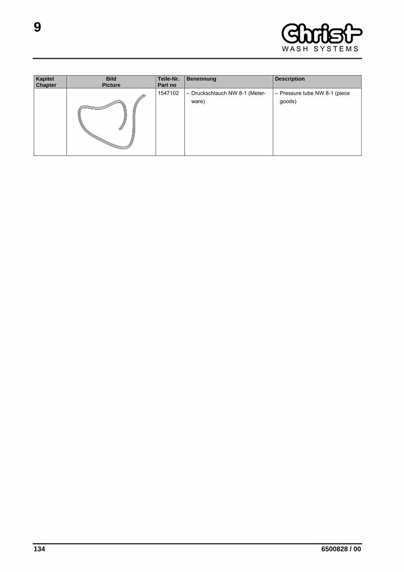
9
134 6500828 / 00
Kapitel Chapter
Bild Picture
Teile-Nr. Part no
Benennung Description
1547102 – Druckschlauch NW 8-1 (Meter-ware)
– Pressure tube NW 8-1 (piece goods)

9
6500828 / 00 135
9.1 Luftplatte komplett Air plate complete
Kapitel Chapter
Bild Picture
Teile-Nr. Part no
Benennung Description
5802047 Luftplatte komplett Air plate complete
5802044 – Luftmodul III – Air module III
1600690 • Manometer 0-10 bar D=40 mm R1/8"
• Manometer 0-10 bar D=40 mm R1/8"
1601600 • Druckregler EAR 2500 1/4" • Pressure regulator EAR 2500 1/4"
1268808 • Winkeleinschraubanschluss Ø 10 - ¼" schwenkbar
• Swivelling screw-in gland el-bow Ø 10 - ¼" hinged
1305802 • Kugelhahn ¼" • Ball valve ¼"
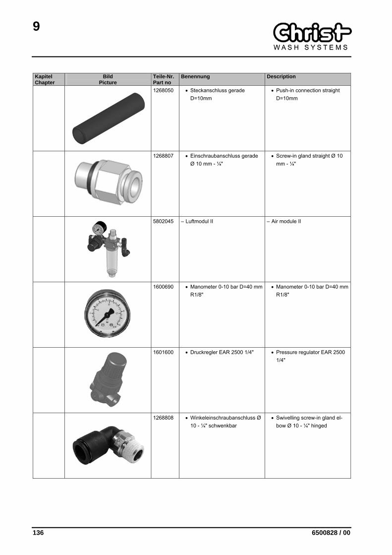
9
136 6500828 / 00
Kapitel Chapter
Bild Picture
Teile-Nr. Part no
Benennung Description
1268050 • Steckanschluss gerade D=10mm
• Push-in connection straight D=10mm
1268807 • Einschraubanschluss gerade Ø 10 mm - ¼"
• Screw-in gland straight Ø 10 mm - ¼"
5802045 – Luftmodul II – Air module II
1600690 • Manometer 0-10 bar D=40 mm R1/8"
• Manometer 0-10 bar D=40 mm R1/8"
1601600 • Druckregler EAR 2500 1/4" • Pressure regulator EAR 2500 1/4"
1268808 • Winkeleinschraubanschluss Ø 10 - ¼" schwenkbar
• Swivelling screw-in gland el-bow Ø 10 - ¼" hinged
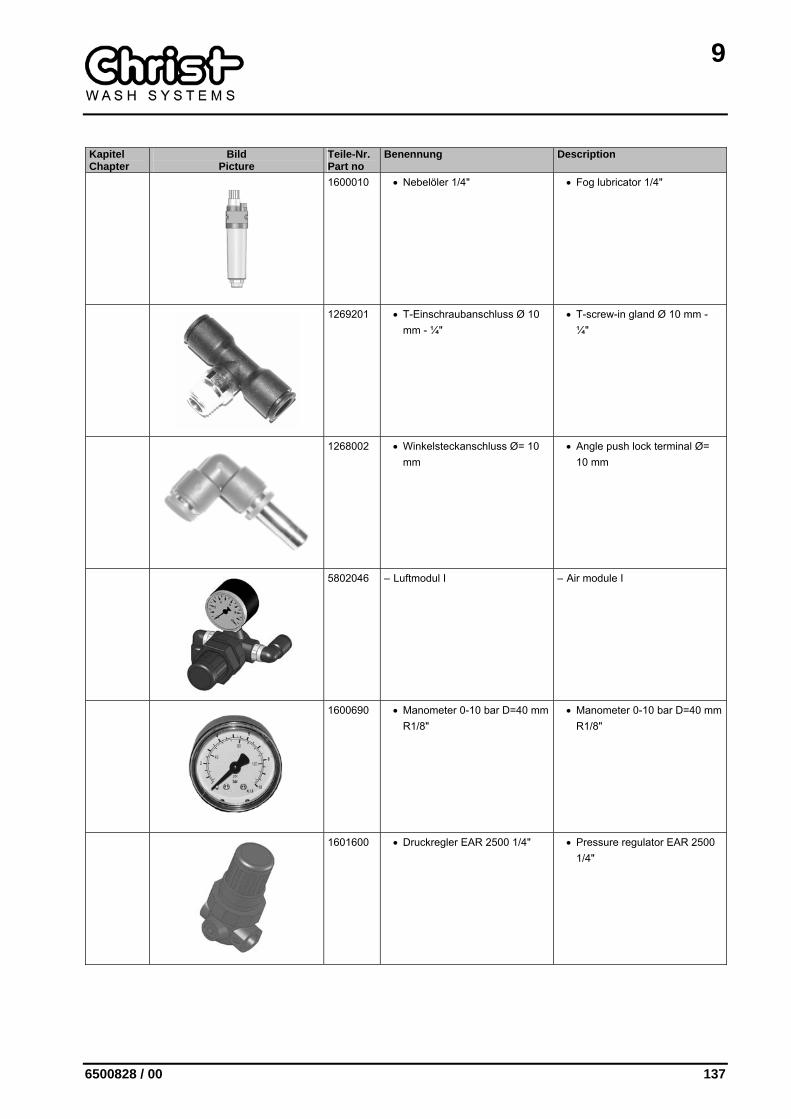
9
6500828 / 00 137
Kapitel Chapter
Bild Picture
Teile-Nr. Part no
Benennung Description
1600010 • Nebelöler 1/4" • Fog lubricator 1/4"
1269201 • T-Einschraubanschluss Ø 10 mm - ¼"
• T-screw-in gland Ø 10 mm - ¼"
1268002 • Winkelsteckanschluss Ø= 10 mm
• Angle push lock terminal Ø= 10 mm
5802046 – Luftmodul I – Air module I
1600690 • Manometer 0-10 bar D=40 mm R1/8"
• Manometer 0-10 bar D=40 mm R1/8"
1601600 • Druckregler EAR 2500 1/4" • Pressure regulator EAR 2500 1/4"
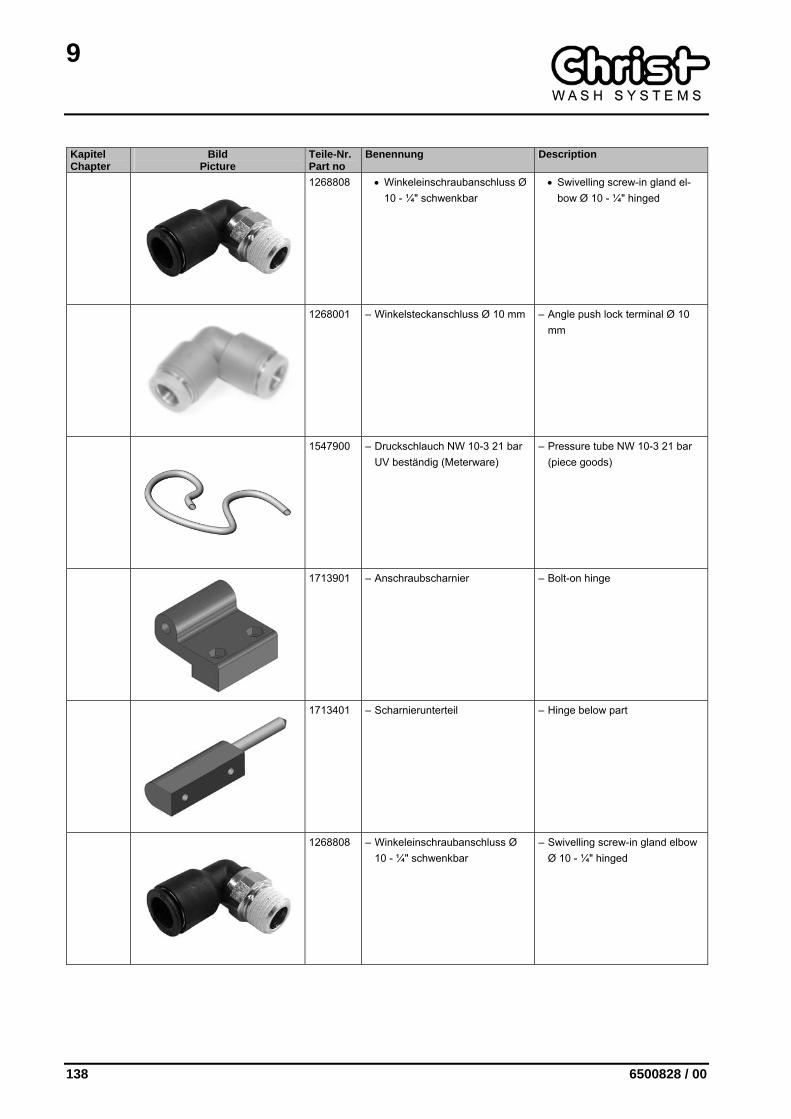
9
138 6500828 / 00
Kapitel Chapter
Bild Picture
Teile-Nr. Part no
Benennung Description
1268808 • Winkeleinschraubanschluss Ø 10 - ¼" schwenkbar
• Swivelling screw-in gland el-bow Ø 10 - ¼" hinged
1268001 – Winkelsteckanschluss Ø 10 mm – Angle push lock terminal Ø 10 mm
1547900 – Druckschlauch NW 10-3 21 bar UV beständig (Meterware)
– Pressure tube NW 10-3 21 bar (piece goods)
1713901 – Anschraubscharnier – Bolt-on hinge
1713401 – Scharnierunterteil – Hinge below part
1268808 – Winkeleinschraubanschluss Ø 10 - ¼" schwenkbar
– Swivelling screw-in gland elbow Ø 10 - ¼" hinged
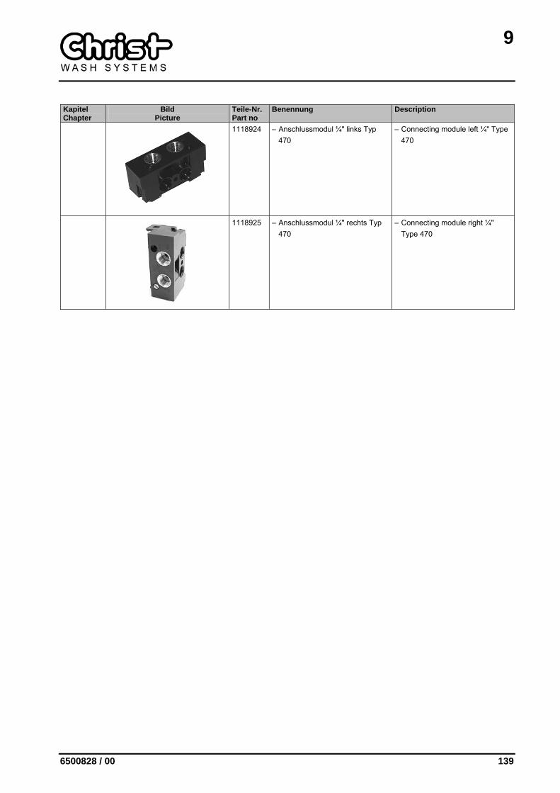
9
6500828 / 00 139
Kapitel Chapter
Bild Picture
Teile-Nr. Part no
Benennung Description
1118924 – Anschlussmodul ¼" links Typ 470
– Connecting module left ¼" Type 470
1118925 – Anschlussmodul ¼" rechts Typ 470
– Connecting module right ¼" Type 470

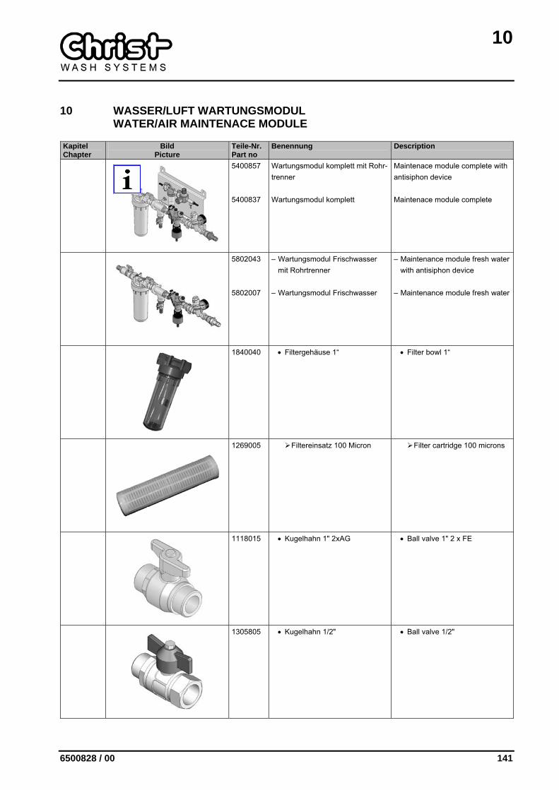
10
6500828 / 00 141
10 WASSER/LUFT WARTUNGSMODUL WATER/AIR MAINTENACE MODULE
Kapitel Chapter
Bild Picture
Teile-Nr. Part no
Benennung Description
5400857 5400837
Wartungsmodul komplett mit Rohr-trenner Wartungsmodul komplett
Maintenace module complete with antisiphon device Maintenace module complete
5802043 5802007
– Wartungsmodul Frischwasser mit Rohrtrenner
– Wartungsmodul Frischwasser
– Maintenance module fresh water with antisiphon device
– Maintenance module fresh water
1840040 • Filtergehäuse 1“ • Filter bowl 1“
1269005 Filtereinsatz 100 Micron Filter cartridge 100 microns
1118015 • Kugelhahn 1" 2xAG • Ball valve 1" 2 x FE
1305805 • Kugelhahn 1/2" • Ball valve 1/2"
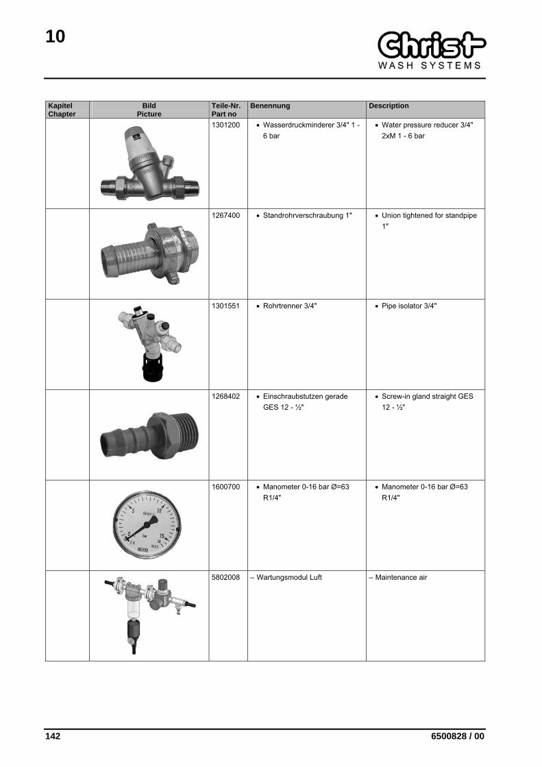
10
142 6500828 / 00
Kapitel Chapter
Bild Picture
Teile-Nr. Part no
Benennung Description
1301200 • Wasserdruckminderer 3/4" 1 - 6 bar
• Water pressure reducer 3/4" 2xM 1 - 6 bar
1267400 • Standrohrverschraubung 1" • Union tightened for standpipe 1"
1301551 • Rohrtrenner 3/4" • Pipe isolator 3/4"
1268402 • Einschraubstutzen gerade GES 12 - ½"
• Screw-in gland straight GES 12 - ½"
1600700 • Manometer 0-16 bar Ø=63 R1/4"
• Manometer 0-16 bar Ø=63 R1/4"
5802008 – Wartungsmodul Luft – Maintenance air
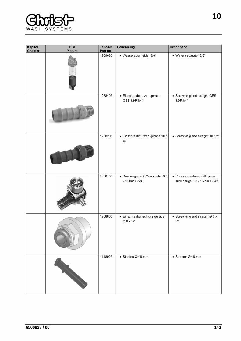
10
6500828 / 00 143
Kapitel Chapter
Bild Picture
Teile-Nr. Part no
Benennung Description
1269680 • Wasserabscheider 3/8" • Water separator 3/8"
1268403 • Einschraubstutzen gerade GES 12/R1/4"
• Screw-in gland straight GES 12/R1/4"
1268201 • Einschraubstutzen gerade 10 / ¼"
• Screw-in gland straight 10 / ¼"
1600100 • Druckregler mit Manometer 0,5 - 16 bar G3/8"
• Pressure reducer with pres-sure gauge 0,5 - 16 bar G3/8"
1268805 • Einschraubanschluss gerade Ø 6 x ¼"
• Screw-in gland straight Ø 6 x ¼"
1118923 • Stopfen Ø= 6 mm • Stopper Ø= 6 mm