
Portable Rebar Cutter/Bender Model VB 16Y - hitachi … · Portable Rebar Cutter/Bender Model VB...
12
Portable Rebar Cutter/Bender Model VB 16Y Handling instructions NOTE: Before using this Electric Power Tool, carefully read through these HANDLING INSTRUCTIONS to ensure efficient, safe operation. It is recommended that these INSTRUCTIONS be kept readily available as an important reference when using this power tool.
Transcript of Portable Rebar Cutter/Bender Model VB 16Y - hitachi … · Portable Rebar Cutter/Bender Model VB...

Portable Rebar Cutter/Bender
Model VB 16Y
Handling instructions
NOTE:
Before using this Electric Power Tool, carefully read through theseHANDLING INSTRUCTIONS to ensure efficient, safe operation. It isrecommended that these INSTRUCTIONS be kept readily availableas an important reference when using this power tool.

1
GENERAL OPERATIONAL PRECAUTIONS
WARNING! When using electric tools, basic safetyprecautions should always be followed to reduce the riskof fire, electric shock and personal injury, including thefollowing.Read all these instructions before operating this productand save these instructions.For safe operations:1. Keep work area clean. Cluttered areas and benches
invite injuries.2. Consider work area environment. Do not expose
power tools to rain. Do not use power tools in dampor wet locations. Keep work area well lit.Do not use power tools where there is risk to causefire or explosion.
3. Guard against electric shock. Avoid body contactwith earthed or grounded surfaces (e.g. pipes,radiators, ranges, refrigerators).
4. Keep children and infirm persons away. Do not letvisitors touch the tool or extension cord. All visitorsshould be kept away from work area.
5. Store idle tools. When not in use, tools should bestored in a dry, high or locked up place, out of reachof children and infirm persons.
6. Do not force the tool. It will do the job better andsafer at the rate for which it was intended.
7. Use the right tool. Do not force small tools orattachments to do the job of a heavy duty tool. Donot use tools for purposes not intended; for example,do not use circular saw to cut tree limbs or logs.
8. Dress properly. Do not wear loose clothing orjewelry, they can be caught in moving parts. Rubbergloves and non-skid footwears are recommendedwhen working outdoors. Wear protecting haircovering to contain long hair.
9. Use eye protection. Also use face or dust mask ifthe cutting operation is dusty.
10. Connect dust extraction equipment.If devices are provided for the connection of dustextraction and collection facilities ensure these areconnected and properly used.
11. Do not abuse the cord. Never carry the tool by thecord or yank it to disconnect it from the receptacle.Keep the cord away from heat, oil and sharp edges.
12. Secure work. Use clamps or a vise to hold the work.It is safer than using your hand and it frees bothhands to operate tool.
13. Do not overreach. Keep proper footing and balanceat all times.
14. Maintain tools with care. Keep cutting tools sharpand clean for better and safer performance. Followinstructions for lubrication and changingaccessories. Inspect tool cords periodically and ifdamaged, have it repaired by authorized servicecenter. Inspect extension cords periodically andreplace, if damaged. Keep handles dry, clean, andfree from oil and grease.
15. Disconnect tools. When not in use, before servicing,and when changing accessories such as blades, bitsand cutters.
16. Remove adjusting keys and wrenches. Form thehabit of checking to see that keys and adjustingwrenches are removed from the tool before turningit on.
17. Avoid unintentional starting. Do not carry a plugged-intool with a finger on the switch. Ensure switch is offwhen plugging in.
18. Use outdoor extension leads. When tool is usedoutdoors, use only extension cords intended foroutdoor use.
19. Stay alert. Watch what you are doing. Use commonsense. Do not operate tool when you are tired.
20. Check damaged parts. Before further use of the tool,a guard or other part that is damaged should becarefully checked to determine that it will operateproperly and perform its intended function. Checkfor alignment of moving parts, free running ofmoving parts, breakage of parts, mounting and anyother conditions that may affect its operation. Aguard or other part that is damaged should beproperly repaired or replaced by an authorizedservice center unless otherwise indicated in thishandling instructions. Have defective switchesreplaced by an authorized service center. Do not usethe tool if the switch does not turn it on and off.
21. WarningThe use of any accessory or attachment, other thanthose recommended in this handling instructions,may present a risk of personal injury.
22. Have your tool repaired by a qualified person.This electric tool is in accordance with the relevantsafety requirements. Repairs should only be carriedout by qualified persons using original spare parts.Otherwise this may result in considerable dangerto the user.
PRECAUTIONS ON USING PORTABLE REBARCUTTER/BENDER
WARNING!1. Be sure to use the unit with the rated voltage specified
on the nameplate. Use of the unit at a voltageexceeding the specification on the nameplate canresult in a dangerously high rotation speed and injury.
2. Avoid any work exceeding the maximum capacitiesof the unit described in the specifications. Never cutand/or bend any hard materials such as PC (Precastconcrete) steel, etc. Materials of this type are likely toscatter into pieces and cause injuries.
3. If the unit malfunctions during operation or you hearany abnormal noise, immediately turn off the switchand stop operation. Contact the store where youbought the unit or an Authorised Hitachi ServiseCenter, and ask for checkup and/or repair. Use of theunit without checkup and repair can result in injury.
4. Make absolutely sure that the cutter cover is closedwhen you don’t carry out the cutting work. If the coveris kept open, the cutter can jam on foreign objectsand cause serious accidents. (Fig. 1)
Fig. 1
Inner cover
Lever
Cover
Gear cover

2
Voltage 230 V 240 V
Power Input 570 W 590 W
Capacities (1) Material: Rebar, equivalent grades: 250N, 300E, 500L, 500N, 500E
Number of piece(s) that Cutting Bendingcan be processed at one time ø10 mm 2 pieces ø10 mm 3 pieces
ø12 mm 1 piece ø12 mm 2 piecesø16 mm 1 piece ø16 mm 1 piece
Weight 17.0 kg (excluding cord)
STANDARD ACCESSORIES
(1) Allen key (For M5 hexagon socket bolt)....................................................... 1 (attached to unit)
(2) One set of cutters ......................... 1 (attached to unit)(3) Carrying case ................................ 1
OPTIONAL ACCESSORIES (sold separately)
1. Cutter
* One set containing two pieces2. Center Roller (D 50) Set
* This is used when the bending diameter of a rebaris changed to (bent diameter: R 25).
3. Center Roller (D 38) Set
* This is used when the bending diameter of a rebaris changed to (bent diameter: R 19).
APPLICATIONS
� Cutting of rebar� Bending of rebar
PRIOR TO OPERATION
WARNING!Before use, check the following items. Concerning items1-7, always be sure to check them before plugging thepower cord into the receptacle.1. Power source
Ensure that the power source to be utilized conformsto the power requirements specified on the productnameplate.Also, avoid using DC power or engine generators. Notonly will the tool get damaged but an accident canresult.
2. Power switchEnsure that the power switch is in the OFF position. Ifthe plug is connected to a receptacle while the powerswitch is in the ON position, the power tool will startoperating immediately, which could cause a seriousaccident.
3. Extension cordWhen the work area is removed from the powersource, use an extension cord of sufficient thicknessand rated capacity. The extension cord should be keptas short as practicable.
CAUTION:
Damaged cord must be replaced or repaired.
50 mm(R25 mm)
SPECIFICATIONS
5. While turning switches, never put your hand close tothe cutter, reaction stopper, or bending roller. Bringingyour hand close to these components can result inserious injury.
6. If you accidentally drop the unit or knock it againstsomething, thoroughly examine the unit and ensurethat there are no damages, cracks, or deformationson the cutter and unit.
7. If you use the machine continuously, the inner coverand gear cover can become hot. After such continuoususe, do not touch the inner cover and gear cover. (Fig. 1)
8. Do not immerse unit in water as this may causemalfunction or electric shock.
CAUTION:� Install the cutter and accessories securely according
to the handling instructions. If you fail to install themproperly, they may come off and cause an injury.
� Be sure to unplug the power cord from the receptaclewhen the cutter is checked, cleaned, and replaced.Failure to do so can result in a serious injury.
38mm(R19 mm)

3
4. Preparation and confirmation of workingenvironmentCheck and confirm if the workplace is in properconditions as mentioned in the general operationalprecautions item 2.
5. For safety sake, use the provided Allen key to makeabsolutely sure that the hexagon socket bolt issecurely clamped. Use of the unit with the bolt in aloosely clamped condition can result in damage tothe unit and cutter as well as accidents.
Read handlinginstructions before use.
Avoid any work exceedingthe maximum capacities.(Rebar diameter ø16 mm)
Do not this electricpower tools in wetwether conditions.
Begin operation only afterensuring that there are nopeople within the turning rangeof the material to be bent.
Never bring your handclose to the cutterduring operation.
PICTGRAPH ILLUSTRATION ANDEXPLANATION
If the switch is turned off and thenimmediately turned on again, the motormay not start. Wait for at least one fullsecond before attempting to turn the motoron again after it has been switched off.
�
ø10ø12
ø16
(Returning Halfway)1 Select RETURN with the dial.1 Pull the trigger.
(Selecting the rebar size)Select the rebar size and thebending angle.
6. Confirm that the cutter is in sharp condition.Make certain that the cutter is in a sharp condition.Continued use of a worn out and deformed cutter withdull edges results in damage to the unit and cutter aswell as accidents.
7. Check plug receptacle.
If a receptacle jounces or a plug comes out easily whena power cord is plugged in, the receptacle needs tobe repaired. Consult the nearest electric service stationfor repair. Continued use of the defective receptaclecan result in overheating and accidents.
4
HOW TO USE (CUTTING)
WARNING!
� Note that the unit is not a hand held tool. Be absolutelysure to use the unit only after placing it on stable spotssuch as floor, ground, etc.
� Never bring your hand close to the cutter duringoperation.
� Never bring your hand close to the reaction stoppersA and B during operation.
� Do not cut any materials other than the rebars. If youattempt to do so, the material can splinter into piecesand scatter.
� Do not cut any rebar exceeding the maximumcapacities of the unit described in the specifications.
� The rebar you are cutting may have a hard spot in it.Quality may vary within each rebar. Do not attemptto cut NON-GRADE rebar.
� The bending roller moves even during cuttingoperation. Never bring your hand close to the bendingroller.
� The cutter blade can get worn out by repeated cuttingof the rebar. Continued use of a worn-out cutter canresult in the damage and the broken pieces flyingaround. Replace it with a new cutter after approximately8,000 times of cutting as a rough guide.
� The machine is so designed that the upper cutter andthe grip rubber can support a rebar.If the grip rubber gets worn out, there is a fear that itcannot sufficiently hold the rebar and gets brokendown with its parts flying around, etc.If the grip rubber cannot hold the rebar much longer,replace it with a new grip rubber. (For replacing thegrip rubber and repairing, ask the store where youpurchased it or the Hitachi Koki Power Tool Center.)
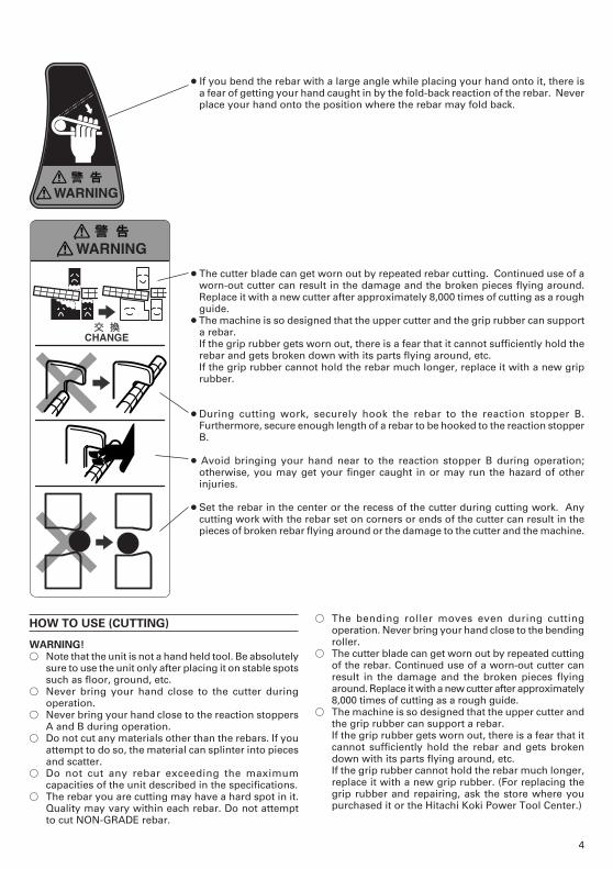
● The cutter blade can get worn out by repeated rebar cutting. Continued use of aworn-out cutter can result in the damage and the broken pieces flying around.Replace it with a new cutter after approximately 8,000 times of cutting as a roughguide.
● The machine is so designed that the upper cutter and the grip rubber can supporta rebar.If the grip rubber gets worn out, there is a fear that it cannot sufficiently hold therebar and gets broken down with its parts flying around, etc.If the grip rubber cannot hold the rebar much longer, replace it with a new griprubber.
● During cutting work, securely hook the rebar to the reaction stopper B.Furthermore, secure enough length of a rebar to be hooked to the reaction stopperB.
● Avoid bringing your hand near to the reaction stopper B during operation;otherwise, you may get your finger caught in or may run the hazard of otherinjuries.
● Set the rebar in the center or the recess of the cutter during cutting work. Anycutting work with the rebar set on corners or ends of the cutter can result in thepieces of broken rebar flying around or the damage to the cutter and the machine.
● If you bend the rebar with a large angle while placing your hand onto it, there isa fear of getting your hand caught in by the fold-back reaction of the rebar. Neverplace your hand onto the position where the rebar may fold back.

5
� During cutting work, securely hook the rebar to thereaction stopper B. Furthermore, secure enoughlength of the rebar to be hooked to the reactionstopper B.
� Set the rebar in the center or the recess of the cutterduring cutting work. Any cutting work with the rebarset on corners or ends of the cutter can result in thepieces of broken rebar flying around or the damageto the cutter and the machine.
1. Cutting (Fig. 2)(1) Turn the lever in the direction of the arrow mark and
open the cover.(2) Set the setting dial at the “cut” position. (Turn the
setting dial all the way clockwise.) (Fig. 2)(3) Set the unit in the position shown in Fig. 2.(4) Set the rebar to be cut on the lower cutter.(5) When the rebar is set, make sure that either the
reaction stopper A or B is hitched to the rebar.(6) Pull the switch trigger and cut the rebar.
CAUTION:� For the sake of safe operation, this unit is designed
so that the switch cannot be inadvertently switchedon. When switching the tool on, press the lock buttonand then pull the switch trigger (Fig. 3). If the switchtrigger is pulled without pressing the lock button first,the switch may be damaged. Please use care whenswitching the tool on.
� Even after the cutting has been completed, continuepulling the switch trigger until the motor starts to runin the reverse direction and the cutter starts to return.If the switch trigger is released too early, the cutterwill not return and the trigger will have to be pulledagain.
� If the switch is turned off and then immediately turnedon again, the motor may not start. Wait for at leastone full second before attempting to turn the motoron again after it has been switched off.
� A slip clutch is built in the machine to protect themechanism.If you process the material with the diameter or qualitybeyond the capacity, the slip clutch can sometimesfunction. In such a case, stop processing immediatelyand check the material.When the slip clutch works, a big slip noise occurs,but it’s not a malfunction.
2. Removing the rebar during cutting operation (Fig. 4)If the switch trigger is released in the middle of cutting,the cutter can come to a stop at a halfway position,jumming the rebar in the unit.When this occurs, you can either pull the switch triggeragain and cut off the rebar, or you can free the rebar bybringing the upper cutter back up to the home positionby carrying out the following procedure. (Fig. 4)
Fig. 4
� Removing (Fig. 5)Set the setting dial to the “RETURN” position asshown in Fig. 5 and pull the switch trigger again.
Fig. 5
Fig. 2
Setting dial
Lock button
Switch trigger
Fig. 3
Reaction stopper B
Rebar
Bending roller
Adjusting position
Reactionstopper A
0˚�RETURN
CUT
45˚�
90˚�
135˚� 180˚�

6
SERVICE LIFE AND REPLACEMENT OF THECUTTER
1. Service life of cutter (Fig. 6)Repeated cutting of the rebar can result in the “wearand tear”, “deformation”, “nicked edges”, etc. Usingthe cutter under such circumstances will not onlydamage the machine but also there will be a fear ofthe broken cutter fragments flying around.Replace it with a new cutter after cutting about 8,000pieces of rebar (a rough guide).
Fig. 6
2. Before removing the cutterWARNING!
To prevent accidents, always be sure to turn the switchOFF and unplug the power cord from the receptacle.(1) Pull the switch lightly and let the upper cutter move
slowly. When the hexagon socket bolt that fixes theupper cutter comes out of the cam cover, turn theswitch OFF and stop the motor.
(2) Unplug the power cord from the receptacle.3. Removal� If you remove the hexagon socket bolt using the
provided Allen key, you can remove the cutter.(Pushing the cutter guard up in the direction of thearrow shown in Fig. 7, facilitates removal of the uppercutter.)
Fig. 7
� Removal of the lower cutter can be easily made if thelower cutter is wrenched with a Phillips head screwdriveras shown in the following diagram. (Fig. 8)
4. Mounting(1) Get rid of dust around the cutter installing section and
clean it up.(2) Align the hole of a new cutter and the position of a
pin, and insert it into the installing section.(3) Also replace the hexagon socket bolt (packed along
with the cutter) with a new one simultaneously,completely tighten it using the attached Allen key, andthen fix the cutter.
HOW TO USE (BENDING)
WARNING!� Note that the unit is not a hand-held tool. Be absolutely
sure to use the unit only after placing it on a stablespots such as floor, ground, etc.
� Never bring your hand close to the bending rollerduring operation.
� Never bend any materials other than the rebars. If youattempt to do so, the material can splinter into piecesand scatter.
� Do not bend any rebar exceeding the maximumcapacities of the unit described in the specifications.Never bend any hard materials such as PC (Precastconcrete) steel. Materials of this type are likely toscatter into pieces and cause injuries.
� The rebar you are bending may have a hard spot in it.Quality may vary within each rebar. Do not attemptto bend NON-GRADE Rebar.
� Never place your hand onto the bending side of therebar. If you do so, your hand may be caught in themechanical parts.
� Bend less than every 3 pieces of rebar with a 10 mmdiameter, less than every 2 pieces with a 12 mmdiameter, and every 1 piece with a 16 mm diameter.
� Remember that the cutter moves even during thebending operation, thereby, close the cutter coverwithout fail.
� Begin operation only after marking sure that there areno people within the turning range of the material tobe bent.
� Reserve an extra length of at least 200 mm on thebending length of the rebar to be bent. (Fig. 9)If the extra length is not long enough, the rebar cancome off during bending operation, or it can breakinto fragments and scatter dangerously.
Fig. 8Blade
Cutter guard
Upper cutter
Lower cutter
Hexagonsocket bolt

7
Fig. 10
� When bending multiple rebars at one time, some maycome off the bending roller and guide, etc., andtherefore exercise caution and set them horizontally.
� If you bend the rebar with a large angle while placingyour hand onto it, there is a fear of getting your handcaught in by the fold-back reaction of the rebar. Neverplace your hand onto the position where the rebarmay fold back.
� Do not bend more than 50 rebars in one session asthis will overload the motor, and may cause it to burnout.
1. Setting bending angles by setting dial
The bar can be bent according to the angles indicatedon the setting dial, as shown in Fig. 11.
In bending the rebar of 10 mm, 12 mm, and 16 mmdiameters, a difference takes place in the bending angleeven in the same dial position depending upon thedifference of rebar’s thickness. Slightly change aposition of the setting dial depending upon the rebar’sdiameter even with the same bending angle as illustratedin the top diagram on the left column. (Fig. 12)
Fig. 12
Size of rebar Colors of indicated marks
ø10 mm White
ø12 mm Red
ø16 mm Yellow
NOTE:
Even at the same dial setting position, the bendingangle can sometimes differ if the diameter or hardnessof the rebar is different. Use the angle marks merelyas a rough guideline.2. Ordinary bending(1) Set the unit in the position with the turntable up as
shown in Fig. 13.
� Place the rebar on the center plate and set it so that itis horizontal with the turntable surface.If the side that is to be bent is set inclined upward, therebar can come loose from the bending roller whilebending causing it to fly off. (Fig. 10)
Fig. 9
Center plate
Stopper
200 mm
Bending roller
Turn table
Fig. 11
Condition of rebar
Dial indication 45° 90° 135° 180°
180°135°90°45°
0˚�RETURN
CUT
45˚�90˚�
135˚�
180˚�

8
Fig. 13
(2) Make sure that the cover is closed.(3) Set the setting dial at the desired angle.(4) Place the rebar on the stopper of the center plate and
set it correctly as shown in Fig. 9.(5) Pull the switch trigger and bent the rebar.(6) Continue pulling the switch trigger untill the motor
makes reverse rotation and the bending roller startsto return. (Once the bending roller starts to return, itwill automatically return all the way to the homeposition even if the switch trigger is released.)
3. Bending by eye measurement
By pulling the switching trigger little by little, you canbend the rebar to your desired angle by eyemeasurement in addition to the dial setting.
(1) Set the setting dial to a larger angle than you desire.(2) Pull the switch trigger lightly and bend the rebar
slowly.(3) When the rebar is bent to the desired angle, stop
pulling the switch. If the bar is still small of the desiredangle, pull the switch again.
(4) Remove the rebar after bending has been finished.Then, pull the switch once more and return thebending roller to the home position. (Continue pullingthe switch until the bending roller begins reverserotation.)
4. Removing rebar during bending operation
When bending out at a low speed in “bending by eyemeasurement”, the rebar can sometimes get caughtin the bending roller due to its own flexure.If this occurs, you can return the bending roller to thehome position by pulling the switch again after settingthe setting dial to the “return” position. This is thesame method used to remove the rebar when it getscaught during cutting operation. (Fig. 14)
Fig. 14
5. Using hole to fix unit in placeA hole is provided at the center of the unit to fix andstabilize it. This hole comes in quite handy when usedin the following manner. (Fig. 15)
Fig. 15
� For bending operation when the unit is fixed to a workbench.This hole will prove very convenient when the unit isbolted to a suitable work bench. (Bolt size M10, lessthan W3/8.)
MAINTENANCE AND INSPECTION
WARNING!
To prevent accidents, always be sure to turn the switchOFF and unplug the power cord from the receptacle.1. Inspecting the mounting screws
Regularly inspect all mounting screws and ensure thatthey are properly tightened. Should any of the screwsbe loose, retighten them immediately. Failure to doso could result in serious hazard.
2. Maintenance of the motorThe motor unit winding is the very “heart” of thepower tool. Exercise due care to ensure the windingdoes not become damaged and/or wet with oil orwater.
3. Inspecting the carbon brushesFor your continued safety and electrical shockprotection, carbon brush inspection and replacementon this tool should ONLY be performed by a HitachiAuthorized Service Center.
4. Replacing supply cord
If the supply cord of Tool is damaged, the Tool mustbe returned to Hitachi Authorized Service Center forthe cord to be replaced.
NOTE:Due to HITACHI’s continuing program of research anddevelopment, the specifications herein are subject tochange without prior notice.
Switch trigger
BoltTail coverSet screws
Nut
Hole to fix unit

9

10
ItemCode No. Q’ty RemarksNo.
1 319-692 12 319-691 13 320-264 3 M4 × 124 319-690 15 320-427 16 313-082 3 M5 × 167 319-696 18 319-695 19 944-486 2 1AP-20
10 319-678 111 320-420 112 319-679 113 319-675 1 ”19, 47, 57, 66”14 307-607 115 316-225 116 319-676 2 M8 × 2517 319-681 118 962-553 119 630-2VV 2 6302VVCMPS2L20 ———— 221 319-660 1 ”19, 20, 53, 65, 71”22 316-213 1 ”23, 25”23 316-214 1 D3 × 1224 949-215 2 M4 × 825 316-212 126 316-212 127 962-569 128 987-203 1 M4 × 1229 319-685 130 319-686 131 ———— 132 319-680 133 311-699 1 4MM34 319-694 135 319-714 1 ”6, 37, 41”36 319-693 137 313-077 1 M5 × 2538 875-638 1 S-1239 320-425 140 320-426 141 ———— 142 301-653 7 D4 × 2043 319-697 144 949-749 1 D3 × 845 967-124 2 7 × 7 × 2246 948-081 2 7 × 7 × 2547 316-186 148 319-677 149 ———— 150 319-682 151 998-468 1 7 × 7 × 1252 319-683 153 930-076 154 319-661 155 316-228 2 M4 × 1056 880-474 7 M6 × 1657 954-789 158 319-707 1 ”59-64”59 930-511 1 4 × 4 × 1060 319-708 161 319-709 162 319-710 163 319-711 164 939-543 1
ItemCode No. Q’ty RemarksNo.
65 600-0VV 1 6000VVCMPS2L66 316-185 167 319-684 1 ”68-70”68 ———— 169 ———— 170 ———— 171 608-VVM 1 608VVC2PS2L72 319-668 173 939-540 174 971-750 2 3 × 3 × 2075 319-664 176 319-663 177 319-666 178 319-667 179 319-673 180 320-424 1 M1281 319-674 1 M12 × 2082 319-688 183 319-687 184 872-470 1 S-2685 878-181 2 M5 × 1586 319-662 187 980-258 288 319-706 289 319-665 190 319-669 191 319-671 192 319-689 193 938-477 2 M5 × 894 935-829 295 999-043 296 971-001 297 313-585 4 M5 × 3098 340-500F 1 ”106”99 980-931 1
100 ———— 1101 316-227 1102 310-111 1103 318-362 2104 ———— 1105 310-146 1 ”93, 96”106 930-703 1107 990-861 1108 953-121 2 D5 × 50109 360-552F 1110 931-701 1111 302-089 2 D5 × 20112 ———— 1113 319-705 1114 995-362 1115 959-140 7 50091116 878-609 1 S-24117 319-718 1118 ———— 1119 319-719 1120 994-273 1121 319-716 1122 316-229 2 M5 × 20123 984-750 2 D4 × 16124 937-631 1
125 1 320-428 1125 2 320-429 1 ”GBR”125 3 320-430 1 ”SUI”126 998-471 2 M5 × 12

404Code No. C99105011 NPrinted in Japan
Hitachi Koki Co., Ltd.


![MEP 2017 06 08 Venezia VR [modalità compatibilità] · PDF file · 2017-06-16Y 1967 FIRST AUTOMATIC WORLDWIDE STIRRUP BENDER MACHINE 8.500 COIL PLANTS INSTALLED AND WORKING IN THE](https://static.fdocuments.in/doc/165x107/5aaf22ba7f8b9a07498ceffc/mep-2017-06-08-venezia-vr-modalit-compatibilit-1967-first-automatic-worldwide.jpg)


