Portable Power From Miniature Combustion Engines
35
Portable Power From Miniature Combustion Engines Derek Dunn-Rankin Mechanical and Aerospace Engineering University of California, Irvine Keynote presentation – Taiwan Combustion Meeting, March 25, 2006
Transcript of Portable Power From Miniature Combustion Engines
Portable Power From Miniature Combustion
Engines
Derek Dunn-RankinMechanical and Aerospace Engineering
University of California, Irvine
Keynote presentation – Taiwan Combustion Meeting, March 25, 2006

New power sources are needed to energize the next
generation technology for autonomy…
Portable Power
Systems
New power sources are needed to energize autonomous technologies
artificial organs
portable air reconnaissance
pervasive computing and communication
personal microclimates
personal robots

MEMS Power
Power and Energy Performance:Current Portable Devices
pager pacemaker > 87,600 hrs (10 years)
Stored Energy (Whr)1.0 10
0.1100 100001000
1
10
100
1000Po
wer
Nee
ded
(W)
1000 hr1 hr
100 hr
10 hr
6 min
36 sec
cell phone
artificial heart
small personal robot
minimal wearable computer
micro aircrafthonda humanoid robot
Bock C-Leg active knee
personal transport
exoskeleton
Desired Portable Device Performance
4G cell phone
UAV-Pointerpersonal microclimate
human endeavor

Power Scales
• 1000 W – microwave oven ~ horse
• 100 W – light bulb ~ human
• 10 W – small laptop ~ bat
• 1 W – cell phone ~ hummingbird
• 10 mW – pager ~ blowfly
• 10 µW – pacemaker ~ fruit fly
• 10000 W – riding lawnmower ~ elephant
PortablePower
images are not to scale

Portable Power Systems Scaling
•Simple Assumptions–15% fuel/energy conversion efficiency
–Fuel specific energy equivalent to liquid hydrocarbons (13kWhr/kg)
–Fuel occupies 66% of system
–Combustion can generate 100 W/cc chamber volume
• Compact Size and Low Mass– 60 g -- 6 kg power source weight– 0.01 -- 0.10 m system length scale– 60 cc -- 6 liter volume
• High Power and Energy – 10 W -- 1000 W power output – 1 hr -- 10 hr operation– 600 -- 6000 Whr/kg specific energy

Mass Specific Power and Energy
1 101
100 100001000
10
100
1000
10000
Stored Specific Energy (Whr/kg)
Sour
ce S
peci
fic P
ower
(W/k
g)
100 hr6 min
10 hr
1 hr
36 sec
3.6 sec
lead acid batterymini-diesel engine
Portable Power Target
Hydrocarbon fuel > 10000 Whr/kg
Solar--100 W/kg
Current technology fails to deliver sufficient energy and power density in the size needed for autonomy
primarylithium
rechargeablelithium
model airplaneengine
fuel cell
human legs
Hydrogen > 30000 Whr/kg
RTG --5 W/kg
high power lead acid
flywheelpneumatic
human metabolism
Elastic elements << 1 Whr/kg
automobileengines
hummingbird metabolism

Power Generation Science and Technology
electricalmechanical workpropulsion
heatmass
electrochemicalbiochemicalthermochemical
reformingrecharging
FuelProcessing
EnergyRelease
PowerExtraction
ExhaustManagement
High EnergyDensity Fuel Benign
Products

for Freedom Car
R.B. Peterson, Proc. IMechE, J. Power and Energy, vol. 219, pg. 371, 2005
Podolski, W. (2004) Fuel Cell Vehicles – Federal Perspective; Fuel Cell Vehicles
Fuel and Fuel Storage
Fuels with assumed 10% conversion efficiency

Energy Release & Power Extraction• Electrochemical
– batteries– supercapacitors– fuel cells
• Thermochemical– Stirling– rotary engine– turbine– pulse combustor– reciprocating engine– Swiss roll burner– film combustor
• Biochemical– biomolecular motor– biofuel cell– metabolic engine
• Electromechanical– compact generators– artificial muscle
• Thermomechanical– shape memory alloys– pressurized gas
• Thermoelectrics– nanowires– thermophotovoltaics
• Power Harvesting– solar– microwave reception– extraneous motion– vibration
• Chemomechanical– biomuscle
energy release power extraction

Fuel Cells• Rapid refueling• Low temperature• Direct conversion
to electricity• High theoretical
efficiency
Temperature C
Max
. The
rmod
ynam
ic E
ffic
ienc
y
AIR
FUEL e-
Typical fuel cell efficiency ~50%
Typical engine efficiency ~25%

LOADe
PRODUCT GASESRESIDUAL FUEL
FUEL OXIDANT
ANODE CATHODEELECTROLYTE(ION CONDUCTOR)
PRODUCT GASES RESIDUAL OXIDANT
ee
SOFCH2
H2OO O2
PAFCand
PEMFCH2
H2O
O2H+
MCFCH2
CO2
H2OCO3
CO2
O2
1000°C
200°C
90°C
650°C
AFC H2H2O
O2 80°COH-
Fuel Cell Types
Low temperature PEM has high power density and rapid response potential
Courtesy G.S. Samuelsen

Fuel Cell Operation
Load
Courtesy F. Prinz

PEM Membrane Electrode Assembly
Three phase zone-membrane-catalyst-gas
Hydrated H+
ions move freely as hydroniummolecule H3O+
Nafion by DuPont
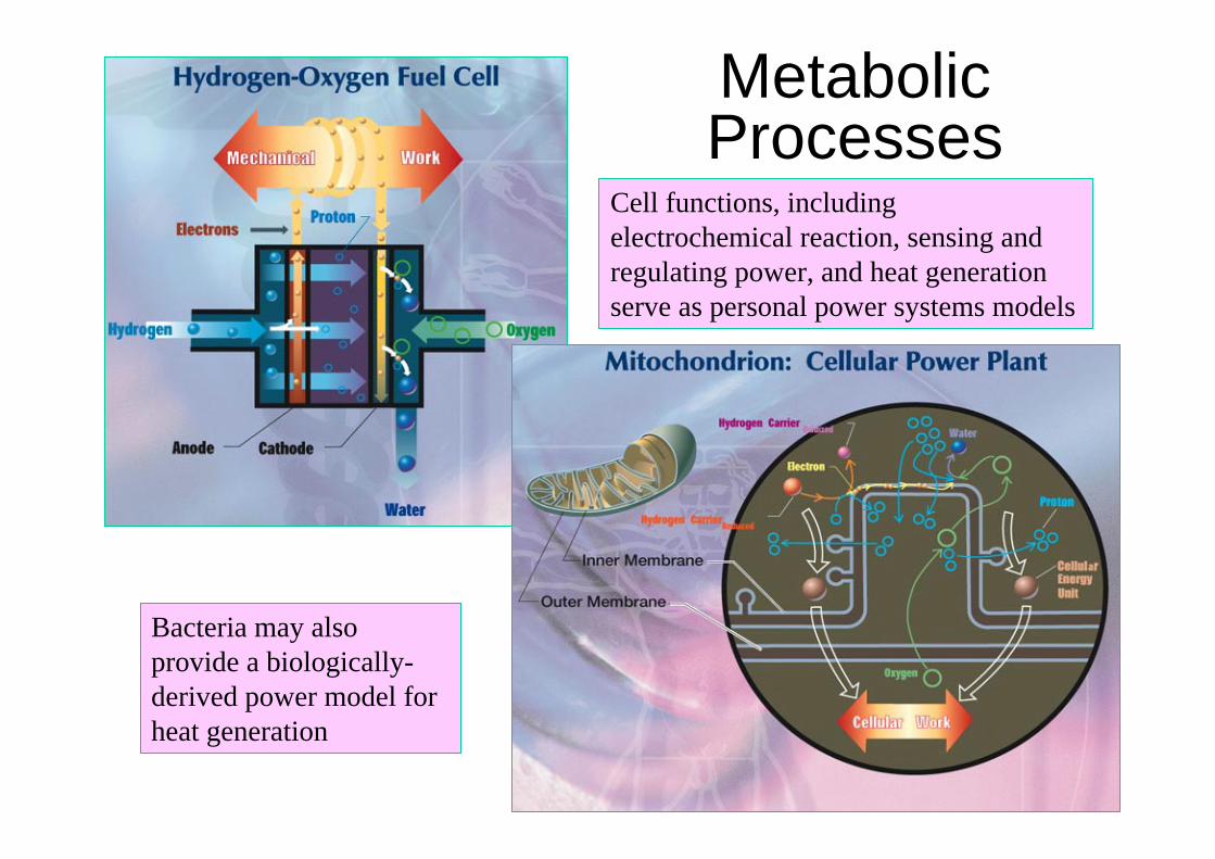
Metabolic Processes
Bacteria may also provide a biologically-derived power model for heat generation
Cell functions, including electrochemical reaction, sensing and regulating power, and heat generation serve as personal power systems models

Muscle Contraction
Up to 80% work/ATP conversion efficiency

Miniature Combustion Systems• Volumetric heat release from liquid fuel will
be necessary for highest power/mass ratios• Combustion is extremely fuel tolerant• Challenges include high surface-to-volume
ratios (thermal issues, flame quenching, short residence times)
• Three miniature combustion approaches– Catalytic JP-8 combustion with Stirling engine– Fuel film combustors– Miniature IC engines

Engine Efficiency with Size
0.1
1
10
100
0.001 0.1 10 1000 100000
Engine Mass (kg)
Est
imat
ed E
ffici
ency
(%)
Manufacturer's DataPower LawOS46 - MfrOS46- Meas.AP YellowJacket - Meas.AP Wasp - Meas.Cox Tee Dee - Meas
Courtesy of Chris Cadou, Univ. of Maryland

Powerplant Efficiency Viewpoint
1
10
100
10 100 1000 10000 100000 1000000
Storage Efficiency Qr (W-Hr/Kg)
Pow
erpl
ant E
ffici
ency
ηpw
r (%
)
JP10
Batteries
Model Aircraft Engine
DARPA DMFCObjective
Endurance = 0.1min 1.0 min
100 min10 min
1000 min
Courtesy of Chris Cadou, Univ. of Maryland

center for C ombustion StudiesYale
UCSD, February 14, 2005
• Electospray in multi-jet mode
• Whirled air injection to promote fuel/air mixing in smallest volume
• Design can be conformed to different geometries (e.g., planar, toroidal, cylindrical)
AdjustableLength
CatalyticLayers
Whirl(~4.5 L/min)
Axial(~0 L/min)
High-DensityCell Filter
TeflonFlange
PyrexChimney
HeatingTube AIR
(20 C)
GroundedRing
Swirl Mixer
FUEL
HV
COMBUSTION
Electrospray + Catalytic Combustion Concept
Courtesy of A. Gomez

center for C ombustion StudiesYale
UCSD, February 14, 2005
Free-Piston Stirling Engine Power Converter: from jet fuel to electric power
Courtesy of A. GomezApprox. 150 mm x 300 mm
Approx. 1 kg
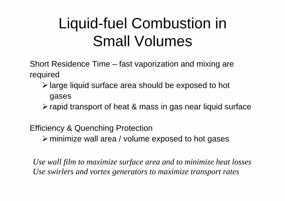
Liquid-fuel Combustion in Small Volumes
Short Residence Time – fast vaporization and mixing are required
large liquid surface area should be exposed to hot gasesrapid transport of heat & mass in gas near liquid surface
Efficiency & Quenching Protectionminimize wall area / volume exposed to hot gases
Use wall film to maximize surface area and to minimize heat lossesUse swirlers and vortex generators to maximize transport rates

Film Combustor Configuration
Liquid Film
Liquid Film
FlameStreamlines
Swirling Air
Recirculation Caused by Strong Swirl

Sapphire Chamber

Chemiluminescence
Visible CH C2 OH
Top of sapphire tube
Base of sapphire tube

Flame Structure

• Four-stroke, compression ignition with resistively heated platinum catalyst glow plug
• Single cylinder, displacement = 4.89 cc
• Carburetor• Lubrication, oil premixed into fuel
• Weight, 279 g
O.S. Engine FS-30S
112 mm
86.5 mm
44 mm
Miniature IC Engine

Miniature Engine Dyno
FlywheelOptical Encoder
Motor
Pressure Transducer
Optical Fiber
PMT
PlenumAir rotameters
Fuel
Potentiometer
Scale
Dilution Tank
Exhaust Condensation and Collection
Buret
Thermocouple
Thermocouple
Engine

Small Engine Dyno
Optical fibre
Pressure transducer
Fuel tank
Valve pushrods
Exhaust line

Cylinder Head Instrumentation
Fiber optic alongside pressure transducer

Cylinder Pressure and Luminosity
Temperature = 143 C
-300
-200
-100
0
100
200
300
0 1 2 3 4 5 6 7 8 9 10 11 12
Shaft Rotations
Pres
sure
(psi
g)
-0.05
0.05
0.15
0.25
0.35
0.45
0.55
0.65
Lum
inos
ity (V
)
Pressure (psig)Luminosity

0
50
100
150
200
250
0 1 2 3 4 5 6Volume (cc)
Pres
sure
(psi
)
Intake
Compression
Expansion
Exhaust
Indicator Diagram

• The values of Da = 19.1 and Relo = 1048 are low, but consistent with those typical of full size IC engines.
• This engine lies on the boundary between the wrinkled laminar flame and the flamelets-in-eddies regimes.
• No turbulence effect of scaling down to the centimeter scale.
Figure from S.R. Turns, An Introduction to Combustion: Concepts and Applications, McGraw-Hill Inc., 1996.
Turbulence in the Centimeter Scale

Other Miniature Combustors
UCB Mini-Rotary Engine
USC Swiss Roll Burner

Summary• New portable power sources are critical for advancing
autonomous devices• Miniature combustion will be needed for highest
power/weight demands, such as micro air vehicles and mobile robots
• Short residence time and thermal control produce very poor efficiency performance currently
• Taking advantage of film combustion offers a possible solution
• Future and current work includes CFD modeling of the film combustor and new swirl enhancement strategies
• Acknowledgments – Taiwan hosts; Prof. W.A. Sirignano; J. Papac, T.K. Pham, J. Pompa, N. Amade Sarzi, Prof. Y.-C. Chao & Y.-H. Li, National Cheng-Kung University; NSF, UC Energy Institute

THANK YOU!