
PORTABLE MAGNETIC DRILLING MACHINE - Nitto · PDF filePortable Magnetic Drilling Machine. Keep...
22
The specifications and configurations contained in this document are subject to change without prior notice due to improvements we are making day in, day out. Manufactured by : Nitto Kohki Co., Ltd. 2-9-4, Nakaikegami, Ota-ward, Tokyo, 146-8555, Japan Tel : 81 (3) 3755-1111 Fax : 81 (3) 3753-8791 Keep the manual handy – so you can use it whenever necessary. PORTABLE MAGNETIC DRILLING MACHINE Read this manual carefully before operating your Nitto Kohki Portable Magnetic Drilling Machine. Keep this manual with your machine. All users of the Nitto Kohki Portable Magnetic Drilling Machine must read this manual. ATRA ACE Model WO-3200 Professional Tool For One-Touch Type Annular Cutter Only (Side-Lock Type Annular Cutter cannot be used.) Specifications Model WO-3200 Power Supply (Single Phase) 220-240 V ~ 50/60 Hz Drill motor Rated Power Consumption 950 W Rated Current 4.3 A No-load Speed 530 min -1 (rpm) Load Speed 350 min -1 (rpm) Magnet Power Consumption 70 W Drilling Capability HI-BROACH One-touch type AUSTBROACH Hole diameter MAX. φ32 mm (1-1/4”) Plate thickness MAX. 50 mm (2”) Twist Drill MAX. 13 mm (1/2”) Max Magnetic Force 9000 N (2028lbs.) Magnet Size 99 mm x 177 mm (3-7/8” x 7”) Weight 13 kg (28.7lbs.)
Transcript of PORTABLE MAGNETIC DRILLING MACHINE - Nitto · PDF filePortable Magnetic Drilling Machine. Keep...

The specifi cations and confi gurations contained in this document are subject to change without prior notice due to improvements we are making day in, day out.
Manufactured by :
Nitto Kohki Co., Ltd.2-9-4, Nakaikegami, Ota-ward, Tokyo, 146-8555, JapanTel : 81 (3) 3755-1111 Fax : 81 (3) 3753-8791
Keep the manual handy – so you can use it whenever necessary.
PORTABLE MAGNETIC DRILLING MACHINERead this manual carefully before operating your Nitto Kohki Portable Magnetic Drilling Machine. Keep this manual with your machine. All users of the Nitto Kohki Portable Magnetic Drilling Machine must read this manual.
ATRA ACE Model WO-3200Professional Tool For One-Touch Type Annular Cutter Only
(Side-Lock Type Annular Cutter cannot be used.)
Specifi cationsModel WO-3200
Power Supply (Single Phase) 220-240 V~ 50/60 Hz
Drill motor
Rated Power Consumption 950 WRated Current 4.3 ANo-load Speed 530 min-1 (rpm)Load Speed 350 min-1 (rpm)
Magnet Power Consumption 70 W
Drilling CapabilityHI-BROACH One-touch typeAUSTBROACH
Hole diameter MAX. φ32 mm (1-1/4”)Plate thickness MAX. 50 mm (2”)
Twist Drill MAX. 13 mm (1/2”)Max Magnetic Force 9000 N (2028lbs.)Magnet Size 99 mm x 177 mm (3-7/8” x 7”)Weight 13 kg (28.7lbs.)

1
The following Safety notations are used throughout the manual to highlight safety precautions for the user and for the machine.
DANGER: Indicates an imminently hazardous situation which, if not avoided by following the instructions given, will result in death or serious injury.
WARNING: Indicates a potentially hazardous situation which, if not avoided by following the instructions given, could result in death or serious injury.
CAUTION: Indicates a potentially hazardous situation which, if not avoided by following the instructions given, could result in injury or material damage.
Caution: Important precautions for machine or tool setup, operation and maintenance.
Thank you very much for your purchase of Nitto Kohki products.Before using your machine, please read this manual carefully so that you may use it properly to get the most out of it.Please keep the manual handy - so you can use it whenever necessary.
CONTENTS pageGENERAL SAFETY RULES ………………………………… 2POWER TOOL SAFETY ……………………………………… 3ABOUT YOUR NITTO PORTABLE MAGNETIC DRILLING MACINE ………………………………………… 4 1. APPLICATION …………………………………………… 7 2. RECEIVING INSPECTION ……………………………… 7 3. PART NAMES …………………………………………… 7 4. FUNCTIONS OF ELECTRONIC CONTROL ………… 8 5. MACHINE SETUP ……………………………………… 8 6. MACHINE OPERATION ……………………………… 10 7. HOW TO USE A TWIST DRILL ……………………… 13 8. TROUBLESHOOTING ……………………………… 14 9. MAINTENANCE/SERVICE ………………………… 15 10. OPTIONAL PARTS …………………………………… 16 11. ORDERING PARTS …………………………………… 18 12. EXPLODED DIAGRAM: MACHINE ………………… 19 13. EXPLODED DIAGRAM: DRILL MOTOR …………… 20
PICTOGRAPH
Warning: It might be dangerous to operate the power tool if the instructions supplied are not followed.
Do not Allow the main body or the power source to get wet as it will cause electric shock and leakage.
Using this machine improperly could result in serious injury. Read the instruction manual before using.
Wear protective goggles without fail.
Always wear hearing protection.
Wear respiratory protective equipment (PPE).
・Sound Pressure Level :Maximum 85dB(A) according to Clause 1.7.4(f), Annex I, Machinery Directive.
・Sound Power Level :Maximum 91dB(A)・Operating Temperature :5˚C~ 40˚C・Operating Humidity :Maximum 90% at 25˚C・Over-voltage Category :Category Ⅱ according to
IEC664-1・Pollution Degree :Degree 3 according to IEC664-1
・English :Please ask your dealer or distributor for instruction manual in local language(s).
・German :Bitte fragen Sie lhren Händler nach eine Betriebsanleitung in Landessprache.
・French :S'il vous plait, veuillez demandez á votre foumisseur de manuel instruction en langue locale.
・Spanish :Por favor, cantacte con su distribuidor para el manual de instrucciones en español.
・Portuguese :Por favor pessa ao seo agente ou distribuidor o manual de instrucces ih linguagen local.
・Italian :Per Manuale lstruzioni in lingua locale Vi preghiamo di rivolgervi al rivenditore o distributore.
・Dutch :Vraag uw handelaar om een nederladstalige gebruiksaanwijzing.
・Swedish :Be er lokala Åtreförsäljare eller distributör om manualer pá svenska.
・Danish :Venligst henvend Dem til den danske distributør for instructions manualer.
・Polish :Prosze pytac swojego dealera lub dystrybutora o instrukcje obslugi w jezyku localnym.
・中文 :

2
GENERAL SAFETY RULES
WARNINGTO OPERATORS
Always Wear Proper Clothing● Do not wear loose clothing. Loose clothing can
become caught in the drilling machine. This could cause severe injuries. Be careful that loose clothing does not come into contact with the machine.
● Wear non-skid footwear. If you lose your footing, you could contact moving portions of the machine. This could cause severe injuries. Always wear non-skid footwear and remain balanced when using the drilling machine.
● Be careful of long hair. Wear a hat or a hair net to contain long hair. Long hair can become caught in the drilling machine. This will cause severe injuries. Be careful that long hair does not come into contact with the drilling machine.
Always Wear Safety Glasses● Always wear safety glasses. The operation of your
drilling machine will cause fl ying chips and particles. These will cause severe eye injuries. You must always wear safety glasses.
● Not all glasses are safety glasses. Wear only safety glasses that comply with ANSI standards. Not all of the lenses are shock resistant. Ordinary glasses will not provide suffi cient eye protection.
Always Wear Hearing Protection● Always wear hearing protection. The operation of
your drilling machine will cause big sound occurs. These will cause severe hearing loss injuries. You must always wear hearing protection
Wear respiratory protective equipment (PPE)● Wear respiratory protective equipment (PPE) when
working in an environment where dust particles are generated in operation.
Maintain Good Posture● Always wear non-skid footwear and maintain good
posture. Do not use the drilling machine when you are tired. Fatigue or loss of balance could cause you to lose control of the machine. This could cause severe injuries. Always stay balanced. Always keep good posture. Stop using the machine if you are tired.
Never Touch the Cutting Tip● Never touch the moving or cutting tip. Contact with
the moving tip will cause severe injuries. Always keep all parts of your body away from the cutting tip. Always keep your hand and clothing away from the cutting tip.
ABOUT THE WORK AREAKeep Work Area Clean● Always keep your work area clean. Cluttered work
areas cause accidents. Always keep clear of other objects.
● Never use the magnetic drilling machine when it is wet. Always use the drilling machine in a dry area. Do not use the drilling machine in the rain. If you use the machine when it is wet you can get electric shock. If you use the machine in the rain you can get an electric shock.
● Always use the drilling machine in a well-lighted area. Do not use the drilling machine in the dark.
● Avoid all flammable materials. Use of the drilling machine may cause a spark that could ignite a fi re or an explosion. Never use the machine near any fl ammable material.
● Keep away from children. Always keep the drilling machine away from children. Do not operate drilling machine when children are present.
BEFORE OPERATIONMake sure that all parts are free from damage● Make sure that the drilling machine is in good
operating condition. Operation of a damaged machine could result in severe injuries. If there is any damage to the machine, do not use the machine. If there is any damage to the machine, take it to an authorized Nitto dealer for repair.
● Do not attempt service or repair of the drilling machine. All service or repair should be done by an authorized Nitto dealer.
Secure Your Work● Always secure your work piece. Improperly mounted
work can become loose. This can cause severe injuries. Always secure all work.
● Always use a vice or a clamp. Do not attempt to hold any work piece with your hand. Attempting to hold a work piece with your hand may cause severe injuries. Always use a vice or clamp to hold the work piece.
● Always secure your drilling machine. Improperly mounted drilling machine can come loose. This can cause severe injuries. Always secure the drilling machine.
Avoid Clutter● Always stay clear of other objects. Cluttered work
areas cause accidents. Always keep a clean work area and stay away from other objects.
A l w a y s R e m o v e S p a n n e r Wr e n c h e s a n d Adjustment Tools● Always remove spanner wrenches and adjustment
tools after adjustments have been made to the

3
drilling machine. Always remove all adjustment tools before using the drilling machine.
Always Use a Cutter that is Appropriate for Your Work● Always use a Cutter that is appropriate for your
work. Avoid heavy-duty work that is the beyond the capacity of your drilling machine. If the work exceeds the capacity of your drilling machine, this can cause accidents and severe injuries. Always use the drilling machine in accordance with its performance specifi cations.
SAFE HANDLING● Never leave the magnet ic dr i l l ing machine
unattended while it is running. When the machine is unattended, disconnect the power source. Do not leave the work area until the machine comes to a complete stop. Operating the machine while it is unattended can case accidents that may result in severe injuries.
HOW TO STORE YOUR MAGNETIC DRILLING MACHINE● Always store the machine in a dry area.● Always keep the machine out of the reach of
children.HOW TO CARRY YOUR MAGNETIC DRILLING MACHINE● Disconnect the power and turn off the machine
whenever you carry the machine.
MAINTENANCEDo not take apart or modify your magnetic drilling machine.● Do not attempt to disassemble or modify your
magnetic drilling machine. ● Do not modify your magnetic drilling machine.
Modifications can cause accident and severe injuries.
● All service and repairs must be performed by an authorized Nitto dealer. Any attempt to service or repair the machine yourself may result in an accident and severe injuries.
Check all Parts for Damage.● Always inspect the magnetic drilling machine before
use.● Always check that the pilot pin and cutter are in
good condition. Use of the machine with worn pilot pins or worn cutter can cause accidents and severe injuries.
● Inspect all cutter before you put them on the magnetic drilling machine.
● Do not operate the magnetic drilling machine with a damaged or worn cutter. Do not operate the machine
with a damaged or worn pilot pin. Do not operate the machine with any damaged accessory. Operating the machine with any damaged part or accessory can cause accidents and severe injuries. If there is any damage to the magnetic drilling machine do not operate the machine. Take it to an authorized Nitto Dealer for repair.
● Always have the magnetic drilling machine repaired at an authorized Nitto dealer. Always take the magnetic drilling machine to an authorized Nitto dealer for service, repair and replacement parts. If you cannot locate an authorized Nitto dealer near you, please contact your sales representative.
● Always use Nitto genuine parts. The use of improper or non-Nitto parts can cause accidents and severe injuries. Never use unauthorized parts. To obtain genuine Nitto parts, contact your sales agent.
● Do not remove any nameplate from your magnetic drilling machine. Do not remove any labels from your magnetic drilling machine. If any label or nameplate is damaged contact your sales agent for a replacement.
POWER TOOL SAFETY
WARNING● Always make sure that the machine is properly
grounded. If the machine is not properly grounded, someone can get an electric shock.
● If you have any doubt about the grounding of the magnetic drilling machine, contact a licensed electrician.
● Never connect the grounding conductor to a gas pipe. This will result in an explosion and severe injuries or death.
● Always check the grounding conductor. If you have any doubts about the grounding conductor contact a licensed electrician.
● Wiring connections to a grounding rod require the expertise of a licensed electrician. Do not attempt the wire connections yourself. Always contact a licensed electrician.
● Do not abuse the power cord. A damaged power cord can cause an electrocution. A damaged power cord can cause fi res. Always inspect the cord. If the cord is damaged, do not use the magnetic drilling machine.
● Do not carry the machine by the cord. Do not pull the cord to disconnect it from a socket.
● The cord can become damaged from heat, contact with sharp objects or from being twisted. Always inspect the cord. Do not use the machine if the cord

4
is damaged.● Always use a ground fault circuit interrupter. The use
of a ground fault circuit interrupter may be required by government regulations. The failure to use a ground fault circuit interrupter may result in electric shock.
● Avoid starting the magnetic drilling machine abruptly or unintentionally.
● Always make sure that the switch is turned off before connecting the power source.
● Always disconnect the power source and turn off the switch before setting up for work operations. Always disconnect the power and turn off the switch when inspecting work. Always disconnect the power and turn off the switch before attempting any maintenance. Failure to disconnect the power and turn off the switch during set up, inspection or maintenance can cause accidents and severe injuries.
About Your Nitto Portable Magnetic Drilling Machine
DANGERDo not use your portable drilling machine on the ceiling.● Use of the portable drilling machine on the ceiling
is dangerous. The machine could fall. The falling machine could cause severe injuries or death. (Fig.1)
Fig. 1
WARNINGDo not use the Magnet for more than fi ve hours.● More than fi ve hours of uninterrupted operation may
cause a fire. Five hours of uninterrupted operation generates extreme heat in the Magnet. This heat can cause a fire. Do not touch the Magnet. When the Magnet is hot, touching it will cause a severe
burn injury. Never use the Magnet for more than fi ve continuous hours. When you are not using the Magnet, turn the switch to the OFF position and pull the Plug out of the power source.
Do not use the Drill Motor for over 30 minutes.● Uninterrupted operation of the Drill Motor for over 30
minutes generates heat. This heat can cause a fi re. Never use the Drill Motor for over 30 minutes. When you are not using the Drill Motor, turn the switch to the OFF position and pull the Plug from the power source.
Use only on magnetic materials.● Your portable drilling machine cannot be used
on non-magnetic materials, such as aluminum, stainless steel, copper or alloys. The Magnet will not work on non-magnetic materials. Attempting to use the Magnet on non-magnetic materials could cause an accident.
Use caution during wall operation.● When using your portable magnetic drilling machine
on a magnetic wall, always use caution. ● Never stand under the machine. * Never allow anyone to stand under the machine. * Never put any part of your body under the
machine. * If the machine falls, it could result in severe injury
or death.● Always remove Cutting Oil from the Tank or the Jet
Oiler before using the machine on a wall. You must manually apply Cutting Oil to the cutting tool.
Always use a work piece that is at least 9 mm (3/8”) thick.● The work piece must be at least 9 mm (3/8”) thick. If
a work piece is too thin, the magnetic power of your machine will decrease. This will cause the machine to move during operation. This could result in an accident. (Fig.2)
Not less than 9mm (3/8”)
Fig. 2
Use an iron back-up plate.● If the work piece is less than 9mm (3/8”) thick, you
must use an iron back-up plate that is more than 10 mm (13/32”) in thickness. The surface area of the iron back-up plate must he greater than the surface area of the magnet. An appropriate back-up

5
plate is necessary to boost the holding power of the Magnet.(Fig.3)
Use of an inappropriate back-up plate can result in an accident, If the back-up plate is not thick enough or big enough, the machine will come loose during operation. This can result in an accident and severe injuries.
Less than 9mm (3/8”)Place 10mm (13/32”) ormore thick piece iron
Fig. 3
Always keep surfaces clean.● Always keep the Magnet surface clean. Always keep
the work piece surface clean. If there are any foreign objects between the Magnet and the work piece surfaces, this will reduce magnetic power. This could cause the machine to move during operation. This can result in an accident. Keep all surfaces clean of rust, chips or other foreign material.
Do not place the machine over a hole.● Do not attempt to position the Magnet over a hole.
Attempting to straddle a hole will reduce the power of the Magnet. This will cause the work piece to come loose during operation and can cause an accident.
Always use a Safety strap to secure the machine.● If the machine falls, it can cause severe injuries.
There is always a possibility that magnetic power can be lost or reduced because of a power failure. Magnetic power can be lost on rough surfaces. You must take precautions to prevent the machine from falling.
● This machine comes with a Safety strap. The Safety strap is to be used to fasten the machine to the work piece. If you do not use the Safety strap, it is possible that the machine may fall. (Fig.4)
● If use of the Safety strap is not possible because of the size of the work piece, you must use another method of securing the machine. Use a Supporting Magnet Assy to prevent the machine from falling.
● The use of a Supporting Magnet Assy is shown below. (Fig.5)
Supporting Magnet Assy
Fig. 4
Fig. 5
Always set the Magnet in the proper position.● Always set the Magnet parallel to the longitudinal
direction of the material. Failure to set the Magnet in the proper position may result in reduced magnetic power. This can cause the machine to move in operation. This can cause an accident resulting in severe injuries.
● When using on H-section steel, as shown in the figure below, set the Magnet in a direction parallel to the longitudinal direction of the material. This will ensure that the Magnet is in the best position for magnetic attraction.(Fig.6)
● Poor magnetic power may result in damage to the cutter or damage to the work piece.
Fig. 6
Be careful about chips.● Keep your hands away from the cutting area at all
times. During drilling, there will be chips. The chips are sharp. The chips are rotating with the cutter. Any contact with the chips can cause severe injuries.
Do not touch the slug.● Do not touch the slug. The slug is very hot. It will
cause severe burns. Make sure that no one touches the slug. Make sure that there is no one below the work area during operation. Hot slugs will fall. Hot slugs can cause severe burns, other severe injuries, or even death. Always wear protective equipment,

6
including protective headgear, eye protection, hearing protection, and gloves. Do not allow any person without protective equipment to come near the machine.
Do not use your hands to remove chips.● Chips have sharp edges. Use a screwdriver to
remove chips. If you use your hands to remove chips, you can be injured, even if you are wearing gloves. Do not use your hands to remove chips under any circumstances.
The cutting edge is sharp.● Always wear gloves when changing the cutter. The
cutting edge is sharp. If you do not wear gloves, you will be cut. Attempting to change the cutter can result in severe injuries.
Do not use Cutting Oil for other purposes.● Cutting Oil should be used only for drilling. Please
refer to Section 5-5 of this manual for further warnings and instructions about Cutting Oil.
CAUTIONAlways use a compatible Pilot Pin.● The Pilot Pin must be compatible with the cutter. An
improper Pilot Pin may result in an accident. See Section 5-3 to identify compatible Pilot Pins and cutters. The proper Pilot Pin to be used will vary, depending on the type of cutter, the diameter of the cutter, and the length of the cutter.
Do not use power that is generated by an engine-driven welder.● The use of an engine-driven welder as a power
source may cause your magnetic driven machine to malfunction, Power from an engine-driven welder can damage the electronic circuits in your portable drilling machine.
Use a Proper extension cord.● Do not use an extension cord that is too thin. Do
not use an extension cord that is too long. Do not use an extension cord that is wound on a drum. Do not share an extension cord with other motor-driven tools. These uses can cause voltage to drop and can reduce the holding power of the magnetic base, causing the machine to move during operation. This can decrease performance and may cause damage to the machine. (Fig.7)
Extension Cord
Max lengthSize (nominal cross-section area of the conductor)
10 m Min 1.25 mm2 or more20 m Min 2.00 mm2 or more30 m Min 3.50 mm2 or more
Fig. 7
Don’t use this machine on the steel material being electrically welded.● When the electric welder is not properly grounded,
electricity will run through the Atra Ace machine v ia i ts Magnet , causing possib le fa i lure or malfunctioning, which in turn may cause accident.
Don’t force to feed cutter when drilling manually.● Because the Hi-Broach and Aust-Broach have
rather thin cutting edges with less cutting pressure resistance as compared to twist drill, do not force to feed the cutter when drilling manually.
If you feed it with too much force, the cutter may break or end up with shorter life than otherwise.
7
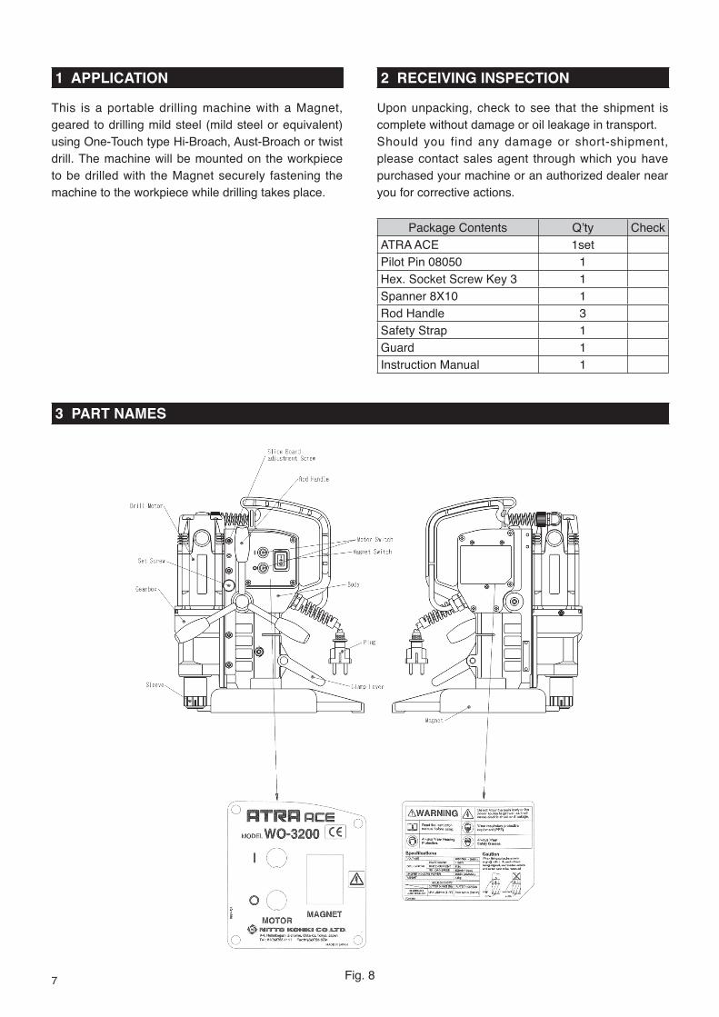
1 APPLICATION
This is a portable drilling machine with a Magnet, geared to drilling mild steel (mild steel or equivalent) using One-Touch type Hi-Broach, Aust-Broach or twist drill. The machine will be mounted on the workpiece to be drilled with the Magnet securely fastening the machine to the workpiece while drilling takes place.
2 RECEIVING INSPECTION
Upon unpacking, check to see that the shipment is complete without damage or oil leakage in transport.Should you find any damage or short-shipment, please contact sales agent through which you have purchased your machine or an authorized dealer near you for corrective actions.
Package Contents Q’ty CheckATRA ACE 1setPilot Pin 08050 1Hex. Socket Screw Key 3 1Spanner 8X10 1Rod Handle 3Safety Strap 1Guard 1Instruction Manual 1
3 PART NAMES
Fig. 8

8
4 FUNCTIONS OF ELECTRONIC CONTROL
4-1. Overload Detecting FunctionThe electric drill shuts down automatically when it is overloaded to prevent the drill or the blade from breaking. To reactivate the drill, press the start switch.
4-2. Re-Start Prevention FunctionThe re-start prevention function comes into play when power failure is restored that has occurred during operation. Thanks to this feature, when a plug that has been disconnected during operation is re-plugged into the receptacle or when power failure that has occurred during operation is restored, the Drill Motor will NOT restart automatically preventing possible accident -- although Magnet Switch lamp will come on and magnetic power restored. To resume operation, turn ON the Motor Switch on the rear of the machine to start the Drill Motor.
4-3. Magnet Interlocking FunctionIf the magnet is disconnected, the Drill Motor will not revolve.When the Magnet fails the Drill Motor will not start revolving. To repair defective Magnet, please contact sales agent through which you have purchased your machine or an authorized dealer near you.
5 MACHINE SETUP
WARNING● When setting up machine, turn off the Magnet
Switch and disconnect the power supply plug from power source.
5-1. Mounting Parts Mount the Rod Handle on the Pinion Shaft.
5-2. Using CutterCAUTION● Use One-Touch type cutters only. ● For better workability and safety, do not use
worn or damaged cutters.
5-3. Combination of Cutter and Pilot Pin CAUTION● Do not use any other combinations than those
shown in the compatibility table.Use a Pilot Pin appropriate for the cutter. (Fig.9)A Pilot Pin to be used varies depending on the cutter type, diameter, length (depth). A wrong combination of cutter and Pilot Pin would not allow slug to be ejected at the end of drilling and/or prevent Cutting Oil from reaching the cutting point, resulting in cutting tool damage.
Fig. 9
5-4. Mounting/Removing Cutter
WARNING● Wear safety gloves when replacing cutter.
CAUTION● Do not use any other combinations of Pilot
Pin and cutter than those shown in the compatibility table.

9
Spindle Arbor
Sleeve
Pull out Turn the Sleeveto the left
Align
Spindle Arbor
SleeveWhite line
Depression
Pilot pin
Cutter
(1) Bring the Drill Motor up by turning the Rod Handle clockwise. (Fig. 10)
Downward Upward
Fig. 10
(2) Insert a Pilot Pin, appropriate for the cutter size, into the cutter. (Fig.11)
Fig. 11(3) Align the depression in the
cutter with the white line on the Sleeve, and then insert the cutter.
When you insert the cutter far enough the Sleeve will turn clockwise and lock with a clicking sound.
* When you find it hard to insert the cutter, turn the Sleeve counterclockwise and do over. (Fig.12)
Fig. 12
(4) To remove the cutter, turn the Sleeve counterclockwise. The cutter will come off. (Fig.13)
Fig. 13
5-5. Preparation of Cutting OilCutting Oil Safety Precautions
WARNING(1) Use● Use Cutting Oil for cutting purpose only. Don’t use it
for household purposes(2) Handling Precautions ● The Cutting Oil contains amine. Do not mix it up
with rust inhibitor, etc. containing nitrite.● Wear safety glasses for eye protection when
handling Cutting Oil: eye injury may results if it gets into your eyes.
● Wear protective gloves for hand protection when handling Cutting Oil: skin injury may result if it comes into contact with your skin.
● Wear respirator when exposure to respiratory hazards with oil mist or vapor is anticipated. Inhalation of oil mist or vapor may make you feel sick.
● When diluting Cutting Oil, follow the instructions per the Operation Manual.
● Keep Cutting Oil out of reach of children.● Don’t drink Cutting Oil.(3) First Aid● If Cutting Oil gets into your eyes, immediately open
your eyelids with your fingers and wash your eyes with plenty of water for at least 15 minutes. If your eyes feel irritated, consult with a medical doctor and follow his/her instructions.
● If Cutting Oil comes into contact with your skin, immediately wash it away with plenty of water and soap. Take off contaminated clothes. Clean the clothes if you need to wear it again. If your skin feels irritated, consult with a medical doctor for medical instructions.
● If someone inhales oil mist or vapor, immediately take him/her to an area where fresh air is abundant and wrap up his/her body with a blanket, etc. to keep body temperature. Have him/her take a rest and consult with a medical doctor for medical instructions.
● If someone drinks Cutting Oil, immediately make him/her drink plenty of water and vomit it. Consult with a medical doctor for medical instructions. When unconscious, do not pour water into his/her mouth nor induce him/her to vomit.
(4) Instructions in Case of Fire● If fi re breaks out in the vicinity, wear PPE (personal
protective equipment) and use foam, powder or CO2 fire extinguisher to put the fire out from the windward.
(5) Storage● When storing Cutting Oil after use, put it into a
container and put a lid on for tight sealing so that dust or moisture, which is a catalyst for contamination, may not get in.
● Avoid direct sunlight, rainwater or the like and store Cutting Oil in a dim cool area.
(6) Disposal● For disposal of concentrate solution and used fl uid,
request a waste-disposal company to dispose them

10
as industrial waste in accordance with the local laws and regulations.
● Treat f lushing water through pH adjustment, condensation/sedimentation, activated sludge process, activated carbon adsorption, etc., and discharge it in accordance with the regulations of your local municipal bylaw.
● Residual dross will remain in an emptied container: be careful when handling an empty container.
(7) Others● When Cutting Oil is poured into another container
for use, post chemical and label information at the site where it is kept. At the same time, keep the Operation Manual handy so that it can be referred to whenever necessary.
● For further details, contact us for product safety data sheet.
● All the information and descriptions that have been provided are based on the currently available documents and information, which may be revised upon our new recognition and/or discovery.
● The precautions provided apply to regular handling. If special handling method is used, take safety measures that are suitable for your applications and usage.
● The information contained herein is for your reference purpose only, to which we make no warranty of any kind and for which we shall not be held responsible.
Preparation of Cutting Oil(1-1) Use our genuine-product Cutting Oil (blue).
I f other Cutt ing Oil is used, the cutt ing performance and service life of cutter would be decreased.
(1-2) Use tap water to dilute Cutting Oil by 8- to 10-fold. Do not use well water.
(1-3) Cutting oil should be supplied to the drill using the Jet Oiler or the Tank, both of which are sold separately.
5-6. Position Change of Rod Handles● Rod Handles can be positioned either on the right
or left side of the machine, by changing the Pinion Shaft insert direction as follows;
(1) Unscrew Hex. Soc. Button Head Screw 8x15 using Hex. Socket Screw Key 5 included in the accessories.
(2) Pull out the Pinion Shaft Assy with Rod Handles as shown in the sketches in Fig. 14.
Pinion ShaftRod Handle
Hex. Soc. Button Head Screw 8X15Washer 30X8.2X3.2
Fig. 14
Always keep the pinion teeth clean and covered with grease.
(3) Insert the Pinion Shaft Assy from the other side of the shaft hole, and put the Screw back.
5-7. Connecting the Power Supply Plug to Power Source
● Before connecting the power supply plug to power source, turn off the switch.
Always use the correct voltage for power source.
6 MACHINE OPERATION
WARNING● Always Wear Safety Glasses.● Always Wear Hearing Protection.● Wear respiratory protective equipment.● Never touch the mounted cutter and the rotating
parts of the machine such as the Spindle Arbor after the power cable is connected to power source.
CAUTION● Do not use hard material such as a screwdriver,
to operate the Motor Switch. This may damage the panel and switch, which would lead to machine failure.
6-1. Start and Stop● The Drill Motor will not rotate unless a Magnet
is turned on in operating the Motor Switch.(1) Start● Magnet ON (Fig.15)
Turning the Magnet Switch ON illuminates the switch lamp and energizes magnetic power.

11
● Drill Motor ON (Fig.16)Turning the Motor Switch ON starts the Drill Motor.
MAGNET MOTOR
push push
Fig. 15 Fig. 16(2) Stop ● Drill Motor OFF (Fig.17)
Turning the Motor Switch OFF stops the Drill Motor.
● Magnet OFF (Fig.18)Turning the Magnet Switch OFF turns off the switch lamp and Magnet power.
MAGNETMOTOR
push
push
Fig. 17 Fig. 186-2. Drilling Procedure
(1) Punch MarkingPut a rather large punch mark in the workpiece by driving a punch down with a hammer. The punch mark will be used as a guide for drilling operation that follows, so it must be made in accurate position. (Fig.19)
Punch Mark
Fig. 19
(2) Keep the Magnet and Workpiece Contacting Surfaces Clean.
WARNING● Always keep surfaces clean.
Always keep the Magnet surface clean. Always keep the work piece surface clean. If there are any foreign objects between the Magnet and the work piece surfaces, this will reduce magnetic power. This could cause the machine to move during operation. This can result in an accident. Keep all surfaces clean of rust, chips or other foreign material.
(3) Aligning with Punch Mark.Turn the Rod Handle counterclockwise to slightly lower the cutter and align the tip of Pilot Pin to the punch mark. (Fig.20)
Punch Mark
Fig. 20
(4) Magnet ON
WARNING● Check to see that Magnetic power is at work.
Turn on the Magnet Switch. The switch lamp will glow and magnetic power will come on.
(5) Mounting the GuardMounting the Guard as shown. (Fig.21)
Guard (TB05418)
Fig. 21
(6) Oil Flow ControlCutting oil should be supplied to the drill using the Jet Oiler or the Tank, which are sold separately.After inserting the cutter and the Pilot Pin, press the Pilot Pin against the workpiece to prepare to feed the cutting oil. If you are using the Jet Oiler, squeeze the oiler body to feed the cutting oil to the unit. If you are using the Tank, open the P-cock to supply cutting oil to the unit.As a guide to the amount of oil to supply to the unit, the drill scrapings should be continuously wet with a fi lm of oil when drilling. Make sure that the scrapings are not discolored by burn marks.When using the drill horizontally, use the Jet Oiler that is sold separately as shown below.

12
Jet Oiler (TQ05273)
Tube 4X7X1000(TQ05275)
Oil ling
Fig. 22
(7) Drill Motor ON
WARNING● Don’t touch revolving parts.
Press the Drill Motor ON Switch to start the Drill Motor
(8) Drilling
WARNING● Don't press the Rod Handle strongly or the
Magnet may lift, causing the main body to swing.
CAUTION● For the first 2 to 3mm (5/64" - 7/64") of the
drilling, operate the drill gradually and only apply a light force to the Rod Handle. (Fig.23)
Feed Slowly2-3mm(5/64"~7/64")
Fig. 23
When putting a hole through workpiece with a tapered bottom surface or bottom surface with a radius, such as angle, channel, H-section steel, etc., use low feed rate at the start as well as toward the end of drilling operation where the likelihood of tool chipping is high.(Fig.24)
R
Fig. 24
(9) Finishing Drilling Operation
WARNING● Be careful about chips.● Do not touch the slug. ● Do not use your hands to remove chips.After completion of drilling operation, lift the Drill Motor and turn OFF the Motor Switch (Fig. 25).When the Drill Motor stops, immediately turn OFF the Magnet Switch (Fig. 26). If the Magnet Switch is kept ON for a long time, the continuous current flowing through the Magnet could shorten the service life of the Magnet.
MAGNET
push
MOTOR
push
Fig. 25 Fig. 26
(10) Removing SlugDon’t proceed to the next operation without removing the slug from the operation just fi nished. At the end of drilling operation slug will pop out automatically ejected by the spring-operated Pilot Pin. Should a slug left in the hold sticking, remove it from the hole by tapping the collar of the slug with a needle stick or something. (Fig.27)
Pilot Pin
Slug (Chips)
Cutter
SlugFlange part
Thin punch
Fig. 27
6-3. Drilling Oblong HoleCAUTIONAlways drill oblong hole slowly.Drill oblong hole in the order of ① ,② ,③ . For the steps② and③ , take care so that the cutter may not be fed into the workpiece with too much force. Spacing between each step of drilling operations should be so arranged that the Pilot Pin will always hit the material yet to be machined. (Fig.28)

13
File away any excesses
Fig. 28
6-4. Drilling Stacked Plates
CAUTION● Remove slug as each plated is finished:
otherwise, being blocked by the slug left unremoved, the cutter cannot cut into the next layer of plate, which results in the Magnet base being pushed up possibly causing accident.
● For stacked plates drilling, always feed and drill slowly and carefully.
● Before drilling stacked plates, securely clamp the plates together in place.
● When drilling stacked plates, retract the cutter as each layer of plate is finished in order to remove slug from the drilling area, then put another hole in the next layer of plate.
7 HOW TO USE THE TWIST DRILL
CAUTIONUse an adapter that is sold separately when using the twist drill.
7-1. How to attach the twist drill
WARNING● When attaching the twist drill, turn off the switch
and unplug the power supply.● Do not use a worn-out twist drill.● Do not use the twist drill that has not been
properly reground.
(1) Lifting up the unitLoosen the clamp lever at the back of the unit and lift it up to tighten the lever securely. By turning the lever with the Lever Handle pulled in the direction of the arrow, you can change the location of the handle freely. On releasing the handle, the spring causes the handle to return to its original position. The handle is then locked in that position. Place the drill in a location that allows it to be operated easily.
(2) Attaching the AdapterAttach the Adapter that is sold separately to the unit. The Adapter can be attached using the same method as shown in “5-4 Mounting/Removing Cutter.”
(3) Attaching the drillTurn the circumference ring on the drill chuck to the left (counterclockwise) to widen out the three hooks at the end of the drill until they are a little larger than the diameter of the drill bit to be inserted.Insert the drill bit in the center of the hooks. Then tighten the drill evenly in three directions with the chuck handle by using the three holes on the side faces of the handle.
7-2. Drilling
WARNING● When drilling with the twist drill the pressing
force tends to be greater than when using the annular blade. Be careful not to press the workpiece so hard that the magnet lifts up.
CAUTIONWhen the twist drill is in use, the built-in cutting oil supply passage cannot be used. Supply cutting oil to the drill externally using the Jet Oiler.
See “6. MACHINE OPERATION” for information on drilling.

14
8 TROUBLESHOOTING
WARNING● Never attempt to repair machine yourself: injury or damage to equipment may result. ● Please feel free to consult the sales agent through which you have purchase your machine or an
authorized dealer, when the following symptoms appear or when you have any questions about our products.
The machine has electronic control. Be sure to turn off all the switches, pull up the electric drill, and then check the machine, when the operator come across to the following situations such as.
Troubleshooting
Problem Causes Solutions
Switch lamp doesn’t come on when Magnet Switch is turned on.
Power supply plug is not connected to socket.
Connect power supply plug to socket.
Drill Motor doesn’t start when Motor Switch is turned on.
Magnet is disconnected. Request for repair.
Drill Motor stops during drilling. (Magnet is not working with Magnet lamp not illuminating.)
Power failure has occurred or power supply plug is disconnected.
After power failure is restored or power supply plug is re-connected, turn on Motor Switch again.
Drill Motor stops during drilling operation. (Lamp blinks in green.)
Feeding force is excessive. Raise the cutter, switch on the Drill Motor again and restart operation.Feed the cutter slowly.

15
9 MAINTENANCE/SERVICE
WARNING ● Always disconnect the power and turn off the
switch before attempting any maintenance.Failure to disconnect the power and turn off the switch during set up, inspection or maintenance can cause accidents and severe injuries.
● Check to see periodically that mounting screws are tight. If you fi nd them loose, retighten.
9-1. Tighten Set Screw When Machine is Not UsedFor the purpose of safety, when you don’t use the machine temporally or on a long-term basis, raise the Drill Motor and set it in position with the Set Screw so that it will not come down on its own weight. If you leave the machine alone with the Drill Motor in a lowered position, the Pilot Pin and/or cutter may be damaged when the machine is relocated. (Fig.29)Before tightening the Set Screw, make sure that the slide section in the Gearbox is properly aligned to the head of the Set Screw.
9-2. Grease the Sliding Surfaces from Time to TimeGrease the machine body and Slide Board from time to time. (Fig.29)
9-3. Gearbox Clearance AdjustmentExcessive clearance between the machine body and Gearbox would deteriorate not only drilling performance but also cutting tool life to a substantial degree. If you find excessive clearance, make adjustment by tightening 5 Slide Board Adjusting Screws on the side of the machine using the same torque all round so that the Drill Motor will not come down on its own weight. (Fig.29)
Fig. 29
9-4. Keep the Tip of Pilot Pin SharpWhen the tip of Pilot Pin gets dull, it sometimes fails to seat into punched hole, causing drilling accuracy to deteriorate. See that the tip is sharp from time to time. If you fi nd it too dull, regrind or replace as required. When regrinding do so carefully, for grinding with too much force may cause the tip to get dull or soften the material to such a degree that it is no longer usable. (Fig.30)
Pilot Pin
Sharpenthe tip
Optimal angle 70˚
Fig. 30
9-5. Recovery Measures When Pilot Pin Gets Jammed
When you change cutting tool you also change Pilot Pin, which acts as a guide for the cutting tool. However there are times when the pin does not come off easy with cutting chips in the clearance between the cutting tool and pin, causing jamming. In such case, tap the tip of Pilot Pin with a wooden hammer, etc., and pull it off. (Fig.31)

16
Cutting chips
Pilot Pin
Cutter
Fig. 31
9-6. Cutter RegrindingWhen you need to regrind cutter, please contact sales agent through which you have purchased your machine or an authorized dealer near you.
9-7. Carbon Brushes Inspection and ReplacementCheck Carbon Brushes for wear periodically.When the length of Carbon Brushes gets as short as 6 mm, replace it with a new one, for, if you don’t, chances are that you’ll have a rectifi cation problem which may cause machine failure. (Fig.32)Check - machine failure.(1) Remove the Brush Cap with a straight slot
screwdriver.(2) Remove the worn-out Carbon Brush and replace
it with a new one. Then reattach the Brush Cap.(3) After replacing the Brush, operate the unit for
about ten minutes with no load.
6mm
Fig. 32
10 OPTIONAL PARTS
10-1. Nitto-Brand Cutting OilCAUTIONUse Nitto-brand Cutting Oil for Atra Ace.
Part No. Part NameTB02621 Cutting Oil 2ℓ (Light Blue)
10-2. Pilot Pin(metric size)
Part No. Part Name Depth(mm) Applicable Cutter(mm)TK00596 Pilot Pin 0625
25Hi-Broachφ12 thruφ17
TJ12696 Pilot Pin 08025Hi-Broachφ17.5 thru 32※ (TK00597) Pilot Pin 0825
TK00694 Pilot Pin 065050
Hi-Broachφ12 thruφ18TJ16019 Pilot Pin 08050
Hi-Broachφ19thruφ32※ (TK00802) Pilot Pin 0850
※ ( ):Special Order
10-3. Supporting Magnet Ass’y
Part No. Part NameTB07689 Supporting Magnet Ass’y
10-4. Twist Drill Adapter (Fig.33)
Part No. Part NameTB07690 Drill Adapter Ass’y
Drill Adapter Ass’y
Fig. 33
10-5. Side-Lock Cutter Adapter (Fig.34)
Part No. Part NameTB05188 Adapter Ass’y
Adapter
Hex. Socket Set Screwwith Dog Point 10X7.5
Fig. 34
10-6. Jet Oiler (Fig.35)
Part No. Part NameTQ10581 Jet OilerTQ05275 Tube 4x7x1000

17
Jet Oiler
Tube 4×7×1000
Fig. 35
10-7. Chip BreakerChip Breaker Ass’y
Part No. Part NameTB07691 Chip Breaker Ass’yTQ11523 Blade
(TP01945) Hex. Socket Head Cap Screw 5×12(TP01939) Hex. Socket Screw Key 4
The part number with ( )are include in the Ass’y parts written above them.
Mounting Chip BreakerCAUTIONWhen setting Chip Breaker, see that the tip of blade may not come into contact with cutting tool.Chip Breaker breaks cutting chips formed in drilling into small pieces and facilitates chip discharging.
Hex. Socket HeadCap Screw 5×12
Blade0.3~0.5mm
Fig. 36
(1) Mount Blade Base. (Fig.36) Use the Hex. Socket head Cap Screws 5 × 12 to
mount a blade to the Blade Base in the direction as shown in the fi gure.
(2) Mount cutter. Loosen the Hex. Socket head Cap Screws 5 × 12
and pull the Blade in the direction as shown by the arrow until it no longer moves. And then, mount a cutter.
(3) Set the blade. Set the Blade in the way that the cutter and the
blade will have a clearance of 0.3 mm - 0.5mm and fasten it securely to the Blade Base with Hex. Socket head Cap Screws 5×12.
10-8. Oil TankOil Tank Ass’y
Part No. Part NameTB07695 Oil Tank Ass’y
Fig. 37

18
10-8. Cutter
Hi-Broach One-Touch Type 25L(metric sizes)Part No. Size(mm) Part No. Part Name Part No. Part Name Part No. Part NameTK00698 12 X25 TK00336 18 X25 TK00343 22.5X25 TK00351 27 X25TK00699 13 X25 TK00337 19 X25 TK00344 23 X25 TK00352 28 X25TK00700 14 X25 TK00338 19.5X25 TK00345 23.5X25 TK00353 29 X25TK00701 15 X25 TK00339 20 X25 TK00346 24 X25 TK00354 30 X25TK00702 16 X25 TK00340 21 X25 TK00347 24.5X25 TK00355 31 X25TK00703 17 X25 TK00341 21.5X25 TK00348 25 X25 TK00356 32 X25TK00335 17.5X25 TK00342 22 X25 TK00349 26 X25
Hi-Broach One-Touch Type 50L(metric sizes)Part No. Size(mm) Part No. Part Name Part No. Part Name Part No. Part NameTK00721 12 x50 TK00727 18 x50 TK00733 24 x50 TK00739 30 x50TK00722 13 x50 TK00728 19 x50 TK00734 25 x50 TK00740 31 x50TK00723 14 x50 TK00729 20 x50 TK00735 26 x50 TK00741 32 x50TK00724 15 x50 TK00730 21 x50 TK00736 27 x50TK00725 16 x50 TK00731 22 x50 TK00737 28 x50TK00726 17 x50 TK00732 23 x50 TK00738 29 x50
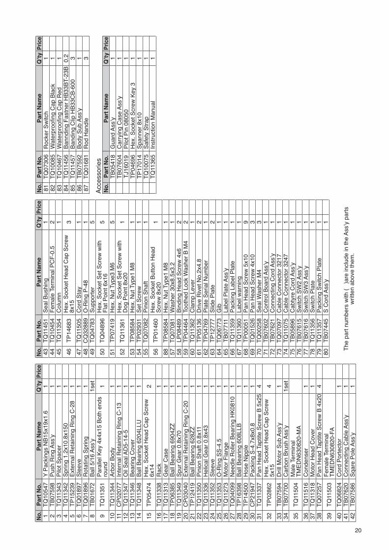
11 Ordering Parts
When ordering parts from sales agent, please be sure to give them part number, part name and quantity.

19
12 E
xplo
ded
Dia
gra
m:
Mac
hin
e
WA
RN
ING
Thi
s di
agra
m is
for
refe
renc
e on
ly. D
o no
t atte
mpt
to s
ervi
ce o
r re
pair
the
Nitt
o P
orta
ble
Mag
netic
Dril
ling
Mac
hine
. Do
not t
ake
the
mac
hine
apa
rt. C
onta
ct a
n au
thor
ized
N
itto
deal
er fo
r al
l ser
vice
and
rep
air
of th
e m
achi
ne. I
mpr
oper
ser
vice
and
rep
air
can
caus
e ac
cide
nts
and
seve
re in
jurie
s. N
ever
atte
mpt
to m
odify
the
mac
hine
. Nev
er
atte
mpt
to s
ervi
ce o
r re
pair
the
mac
hine
you
rsel
f.
1234
5671011
3633
34
34
4041
39
3838
293032
3228
67686970
6566
71
27
26
3131
25 24 23 22 211920 18
37
35
912
8
15
1514 13
17
16
63
6364
62
56
5859
5761
88
84
8572
73
7475
86
7677
7978
80
81
8382
68
54
5352
51
55
60
87
5049
48 47 46 45
44 4342
68
AA
20
No.
Par
t N
o.
Par
t N
ame
Q’t
yP
rice
1T
Q10
547
Y P
acki
ngs
NB
15x1
9x1.
61
2T
B07
598
Pus
h R
ing
Ass
’y1
3T
Q11
343
Pilo
t Spa
cer
14
TQ
1134
2S
prin
g 1.
2x10
.8x1
501
5T
P15
239
Ext
erna
l Ret
aini
ng R
ing
C-2
81
6T
Q01
897
Sle
eve
17
TQ
0189
6R
otat
ing
Spr
ing
18
TB
0167
2B
all 5
/16
Ass
’y1s
et
9T
Q11
351
Par
alle
l Key
4x4
x15
Bot
h en
ds
roun
d1
10T
Q11
344
Arb
or B
ody
111
CP
0207
7In
tern
al R
etai
ning
Rin
g C
-13
112
TQ
1134
7O
il S
eal A
D5-
14-5
113
TQ
1134
6B
earin
g C
over
114
TQ
1134
8B
all B
earin
g 62
04LL
U1
15T
P05
474
Hex
. Soc
ket H
ead
Cap
Scr
ew
6x14
2
16T
Q11
338
Rac
k1
17T
Q11
313
Gea
r C
ase
118
TP
0638
5B
all B
earin
g 69
04Z
Z1
19T
Q11
349
Spu
r G
ear
0.8x
701
20C
P03
040
Ext
erna
l Ret
aini
ng R
ing
C-2
01
21T
P12
419
Bal
l Bea
ring
628Z
Z1
22T
Q11
350
Pin
ion
Sha
ft 0.
8x11
123
TQ
1133
6H
elic
al G
ear
0.8x
431
24T
Q11
352
Sle
eve
125
TQ
1135
3O
-Rin
g S
S-4
.51
26T
Q11
273
Mot
or F
lang
e1
27T
Q04
099
Nee
dle
Rol
ler
Bea
ring
HK
0810
128
TP
1639
8B
all B
earin
g 60
8LLB
129
TP
1450
0H
ose
Nip
ple
130
CP
2194
7P
acki
ng S
-4.7
x8x0
.81
31T
Q11
337
Pan
Hea
d Ta
ptite
Scr
ew B
5x2
54
32T
P02
862
Hex
. Soc
ket H
ead
Cap
Scr
ew
5x15
4
33T
B07
594
Dril
l Mot
or S
ub A
ss’y
134
TB
0770
0C
arbo
n B
rush
Ass
’y1s
et
35T
Q11
504
Mal
e Te
rmin
al
TM
ED
N63
0820
-MA
36T
Q11
516
Con
dens
er1
37T
Q11
318
Mot
or H
ead
Cov
er1
38T
Q07
257
Pan
Hea
d Ta
ptite
Scr
ew B
4x2
04
39T
Q11
503
Fem
ale
Term
inal
T
ME
DN
6308
20-F
A40
TQ
0682
4C
ord
Por
tect
or1
41T
B07
620
Con
nect
ing
Cab
le A
ss’y
142
TB
0758
6S
qare
Pol
e A
ss’y
1
No.
Par
t N
o.
Par
t N
ame
Q’t
yP
rice
43T
Q11
451
Sea
l Bus
hing
144
TQ
1045
4F
emal
e Te
rmin
al P
CF
-0.5
245
TQ
1135
4C
olum
n1
46T
P14
683
Hex
. Soc
ket H
ead
Cap
Scr
ew
8x15
3
47T
Q11
505
Cor
d S
tay
148
CQ
3288
9O
-Rin
g P
-48
149
TQ
0478
3S
uppo
rter
5
50T
Q04
896
Hex
. Soc
ket S
et S
crew
with
F
lat P
oint
6x1
65
51T
P07
419
Hex
. Nut
Typ
e3 M
65
52T
Q11
361
Hex
. Soc
ket S
et S
crew
with
D
og P
oint
8x2
01
53T
P08
584
Hex
. Nut
Typ
e1 M
81
54T
P02
931
Set
Scr
ew1
55T
Q07
082
Pin
ion
Sha
ft1
56T
P01
460
Hex
. Soc
ket B
utto
n H
ead
Scr
ew 8
x20
1
88T
P08
584
Hex
. Nut
Typ
e1 M
81
57T
Q07
081
Was
her
30x8
.5x3
.21
58LP
0848
9B
indi
ng H
ead
Scr
ew 4
x62
59T
P04
464
Toot
hed
Lock
Was
her
B M
42
60T
Q11
362
Cla
mp
Leve
r1
61T
P05
136
Driv
e R
ivet
No.
2x4.
82
62T
P04
769
Pla
te S
eria
l Num
ber
163
TP
1277
7S
lide
Pla
te2
64T
Q06
773
Gib
165
TB
0771
1La
bel P
late
Ass
’y1
66T
Q11
359
Pac
king
Lab
el P
late
167
TQ
1136
0La
bel w
arni
ng1
68T
P00
051
Pan
Hea
d S
crew
5x1
09
69T
Q01
526
Pan
Hea
d S
crew
4x1
03
70T
Q00
258
Sea
l Was
her
M4
371
TB
0760
2C
ontr
ol B
oard
Ass
’y1
72T
B07
621
Con
nect
ing
Cor
d A
ss’y
173
TQ
0709
7C
able
Con
nect
or 3
217
174
TQ
1107
5C
able
Con
nect
or 3
247
175
TB
0589
6C
abty
re C
ord
Ass
’y1
76T
B07
615
Sw
itch
SW
2 A
ss’y
177
TB
0761
6S
witc
h S
W3
Ass
’y1
78T
Q11
356
Sw
itch
Pla
te1
79T
Q11
357
Pac
king
Sw
itch
Pla
te1
80T
B07
445
S C
ord
Ass
’y1
No.
Par
t N
o.
Par
t N
ame
Q’t
yP
rice
81T
Q07
306
Roc
ker
Sw
itch
182
TQ
1008
5W
ater
proofi n
g C
ap B
lack
1
83T
Q10
467
Wat
erpr
oofi n
g C
ap R
ed1
84T
Q11
456
Ban
ndin
g F
astn
er H
B33
BT-
23B
0.2
85T
Q11
457
Ban
ding
Clip
HB
33C
B-6
003
86T
B07
592
Bod
y S
ub A
ss’y
187
TQ
0168
1R
od H
andl
e3
Acc
esso
ries
No.
Par
t N
o.
Par
t N
ame
Q’t
yP
rice
TB
0541
8G
uard
Ass
’y1
TB
0760
4C
arry
ing
Cas
e A
ss’y
1T
J160
19P
ilot P
in 0
8050
1T
P04
696
Hex
. Soc
ket S
crew
Key
31
TP
1701
4S
pann
er 8
x10
1T
Q10
075
Saf
ety
Str
ap1
TQ
1136
5In
stru
ctio
n M
anua
l1
The
par
t num
bers
with
(
)are
incl
ude
in th
e A
ss’y
par
ts
writ
ten
abov
e th
em.

NITTO KOHKI CO., LTD.2-9-4, Nakaikegami, Ota-ward, Tokyo, 146-8555, JapanTel: (03) 3755-1111 Fax: (03) 3753-8791 http://www.nitto-kohki.co.jp
NITTO KOHKI U.S.A ., INC.4525Turnberry Drive, Hanover Park, IL 60103, U.S.A Tel: (630)924-9393 Fax: (630)924-0303
NITTO KOHKI EUROPE CO., LTD.Unit21 The Empire Centre, Imperial Way, Watford, Herts. WD24 4TS, UKTel: (01923)239668 Fax: (01923)248815
NITTO KOHKI DEUTSCHLAND GMBHLerchenstr. 47, D-71144 Steinenbronn, GermanyTel: 49-7157-22436 Fax: 49-7157-22437
NITTO KOHKI CO., LTD. SINGAPORE BRANCH81 Anson Road #08-39 Singapore 079908Tel: 6227-5360 Fax: 6227-0192
NITTO KOHKI AUSTRALIA PTY. LTD.77 Brandl Street Brisbane Technology Park Eight Mile Plains QLD4113, AUSTRALIATel: (07)3340-4600 Fax: (07)3340-4640
Printed in JAPAN
TQ11365
READ ALL INSTRUCTIONS BEFORE OPERATING THIS TOOL
ATRA ACE Model WO-3200PROFESSIONAL TOOL


![GATOR PNEUMATIC MAGNETIC DRILLING MACHINE UNDERWATER … · GATOR PNEUMATIC MAGNETIC DRILLING MACHINE UNDERWATER USE Model ... Mounting of cutters [5] ... Attach an additional piece](https://static.fdocuments.in/doc/165x107/5ae1b18d7f8b9ae74a8b8bf7/gator-pneumatic-magnetic-drilling-machine-underwater-pneumatic-magnetic-drilling.jpg)


