PORTABLE INVERTER GENERATOR GEN2000W120V · PORTABLE INVERTER GENERATOR . GEN2000W120V. ......
21
PORTABLE INVERTER GENERATOR GEN2000W120V READ AND UNDERSTAND THE MANUAL PRIOR TO USING. – 2018-08-06 (REV:01)
Transcript of PORTABLE INVERTER GENERATOR GEN2000W120V · PORTABLE INVERTER GENERATOR . GEN2000W120V. ......

PORTABLE INVERTER GENERATOR
GEN2000W120V
READ AND UNDERSTAND THE MANUAL PRIOR TO USING. –
2018-08-06 (REV:01)
1
INTRODUCTION
Thank you for purchasing this Inverter Generator. Before using this product, please read this manual thoroughly and follow
the instructions carefully.
CONTENTS SAFETY INFORMATION................................................................................................................... 2
CONTROLS & FEATURES.............................................................................................................. 4
PRE-OPERATION CHECK............................................................................................................... 7
OPERATION .......................................................................................................................................9
PERIODIC MAINTENANCE............................................................................................................14
TROUBLESHOOTING .....................................................................................................................17
STORAGE............................................................................................................................................18
SPECIFICATION................................................................................................................................19
WIRING DIAGRAM............................................................................................................................20
2
WARNING
READ AND UNDERSTAND THIS MANUAL COMPLETELY BEFORE OPERATING THE GENERATOR.
SAFETY INFORMATION
EXHAUST FUMES ARE POISONOUS
Never operate the generator in a closed area. It may cause unconsciousness or death within a short period of time.
Operate the generator in a well ventilated area.
FUEL IS HIGHLY FLAMMABLE AND POISONOUS
Always turn off the engine when refueling.
Never refuel while smoking or near an open flame.
Take care not to spill any fuel on the engine or muffler when refueling.
If you swallow any fuel, inhale fuel vapor, or allow any to get in your eyes, seek assistance immediately. If any fuel
spills on your skin or clothing, immediately wash with soap and water and change your clothes.
When operating or transporting the generator, be sure it is kept upright. If it tilts, fuel may leak from the carburetor or
fuel tank.
ENGINE AND MUFFLER MAY BE HOT
Place the generator in a place where passers-by or children are not likely to touch the generator.
Avoid placing any flammable materials near the exhaust outlet during operation.
Keep the generator at least 3 feet from buildings or other equipment, or the engine may overheat.
Avoid operating the engine with a dust cover.
Be sure to carry the generator only by its carry handle.
Put the machine on the flat ground, allowing generator to elminate heat freely.
ELECTRIC SHOCK PREVENTION
Never operate the generator in rain or snow.
Never touch the generator with wet hands or electrical shock will occur.
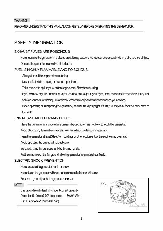
Be sure to ground (earth) the generator. FIG.1
NOTE:
Use ground (earth) lead of sufficient current capacity.
Diameter: 0.12mm (0.005 in)/ampere --8AWG Wire
EX: 10 Ampere --1.2mm (0.055 in)
FIG.1
3
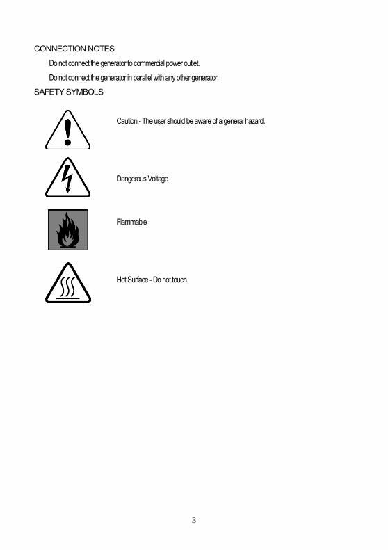
CONNECTION NOTES
Do not connect the generator to commercial power outlet.
Do not connect the generator in parallel with any other generator.
SAFETY SYMBOLS
Caution - The user should be aware of a general hazard.
Dangerous Voltage
Flammable
Hot Surface - Do not touch.

4
CONTROL & FEATURES GENERATOR OVERVIEW (FOR ELECTRIC START TYPE)
(1) Fuel tank (2) Spark plug (3) Muffler
(4) Carrying handle (5) Choke lever (6) Air filter
(7) Fuel pump (8) Fuel cock (9) Recoil starter
(10) Oil filler cap (11) Fuel tank cap (12) Fuel filter
(13) AC pilot light (14) Overload indicator light (15) Oil warning light
(16) Economy control switch (17) DC 12V output (18)USB output
(19) Auto Gen Start (20) Ground (earth) terminal (21) AC protector 20A
(22) AC receptacle (23) DC protector (24) Output reset
(25) Engine start (EC5 receptacle) (26) Engine switch
1 2 3 54 6
9 8 71011
12
16
15
14
13
17
18
20 22
24
19
23
21
25
26
5
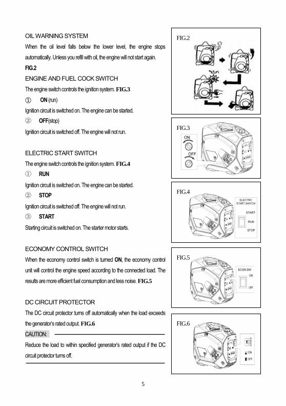
OIL WARNING SYSTEM
When the oil level falls below the lower level, the engine stops
automatically. Unless you refill with oil, the engine will not start again.
FIG.2
ENGINE AND FUEL COCK SWITCH
The engine switch controls the ignition system. FIG.3
① ON (run)
Ignition circuit is switched on. The engine can be started.
② OFF(stop)
Ignition circuit is switched off. The engine will not run.
ELECTRIC START SWITCH
The engine switch controls the ignition system. FIG.4
① RUN
Ignition circuit is switched on. The engine can be started.
② STOP
Ignition circuit is switched off. The engine will not run.
③ START
Starting circuit is switched on. The starter motor starts.
ECONOMY CONTROL SWITCH
When the economy control switch is turned ON, the economy control
unit will control the engine speed according to the connected load. The
results are more efficient fuel consumption and less noise. FIG.5
DC CIRCUIT PROTECTOR
The DC circuit protector turns off automatically when the load exceeds
the generator’s rated output. FIG.6
CAUTION:
Reduce the load to within specified generator’s rated output if the DC
circuit protector turns off.
FIG.2
FIG.3
FIG.5
FIG.6
FIG.4
OFF
ON
STOP
RUN
START
ELECTRICSTART SWITCH
ECON.SW
6
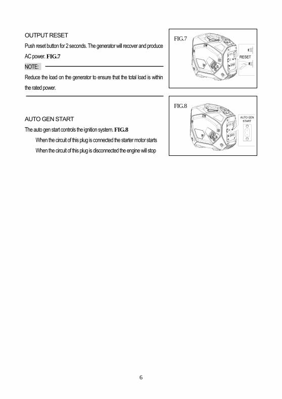
OUTPUT RESET
Push reset button for 2 seconds. The generator will recover and produce
AC power. FIG.7
NOTE:
Reduce the load on the generator to ensure that the total load is within
the rated power.
AUTO GEN START
The auto gen start controls the ignition system. FIG.8
When the circuit of this plug is connected the starter motor starts
When the circuit of this plug is disconnected the engine will stop
FIG.8
FIG.7
RESET
AUTO GENSTART
7
PRE-OPERATION CHECK
NOTE:
Pre-operation checks should be made each time the generator is
used.
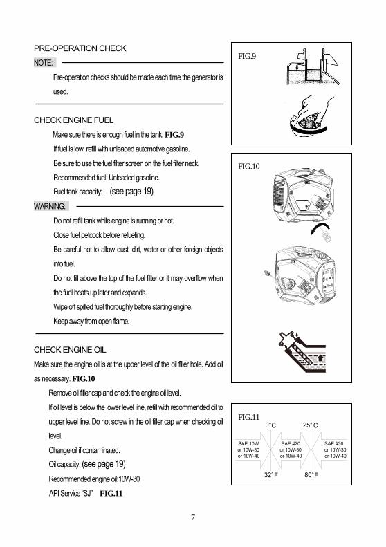
CHECK ENGINE FUEL
Make sure there is enough fuel in the tank. FIG.9
If fuel is low, refill with unleaded automotive gasoline.
Be sure to use the fuel filter screen on the fuel filter neck.
Recommended fuel: Unleaded gasoline.
Fuel tank capacity: (see page 19)
WARNING:
Do not refill tank while engine is running or hot.
Close fuel petcock before refueling.
Be careful not to allow dust, dirt, water or other foreign objects
into fuel.
Do not fill above the top of the fuel filter or it may overflow when
the fuel heats up later and expands.
Wipe off spilled fuel thoroughly before starting engine.
Keep away from open flame.
CHECK ENGINE OIL
Make sure the engine oil is at the upper level of the oil filler hole. Add oil
as necessary. FIG.10
Remove oil filler cap and check the engine oil level.
If oil level is below the lower level line, refill with recommended oil to
upper level line. Do not screw in the oil filler cap when checking oil
level.
Change oil if contaminated.
Oil capacity: (see page 19)
Recommended engine oil:10W-30
API Service “SJ” FIG.11
FIG.11
32°F F80°
25° CC0°
or 10W-30SAE #30
or 10W-40
SAE #20or 10W-30or 10W-40or 10W-40
or 10W-30SAE 10W
FIG.9
FIG.10

8
GROUND (Earth)
WARNING:
It is important to properly ground your generator before using.
Use an 8AWG wire and a small metal earth spike. The wire and
earth spike are not supplied with the unit. FIG.12
CONNECT BATTERY (for electric starting system)
(a) The battery for electric starter should be fixed on the handle of generator.
FIG.13
(b) Connect the battery to the socket on the control panel with the cable
for battery. FIG.14
NOTE:
Make sure the battery is fully charged before using.
Avoid poor contact between battery and socket on control panel.
The battery also can be used as a power bank, please find the
details in the manual for battery.
FIG.14
FIG.12
FIG.13
ENGINESTART
9
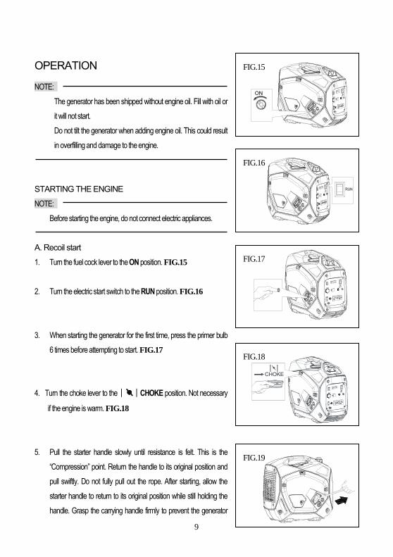
OPERATION
NOTE:
The generator has been shipped without engine oil. Fill with oil or
it will not start.
Do not tilt the generator when adding engine oil. This could result
in overfilling and damage to the engine.
STARTING THE ENGINE
NOTE:
Before starting the engine, do not connect electric appliances.
A. Recoil start
1. Turn the fuel cock lever to the ON position. FIG.15
2. Turn the electric start switch to the RUN position. FIG.16
3. When starting the generator for the first time, press the primer bulb
6 times before attempting to start. FIG.17
4. Turn the choke lever to the│ │CHOKE position. Not necessary
if the engine is warm. FIG.18
5. Pull the starter handle slowly until resistance is felt. This is the
“Compression” point. Return the handle to its original position and
pull swiftly. Do not fully pull out the rope. After starting, allow the
starter handle to return to its original position while still holding the
handle. Grasp the carrying handle firmly to prevent the generator
FIG.15
FIG.16
FIG.18
FIG.19
FIG.17
ON
RUN
CHOKE
10
from falling over when pulling the recoil starter. FIG.19
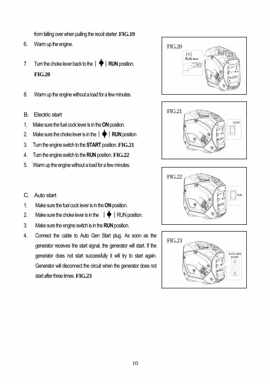
6. Warm up the engine.
7. Turn the choke lever back to the│ │RUN position.
FIG.20
8. Warm up the engine without a load for a few minutes.
B. Electric start
1. Make sure the fuel cock lever is in the ON position.
2. Make sure the choke lever is in the│ │RUN position
3. Turn the engine switch to the START position. FIG.21
4. Turn the engine switch to the RUN position. FIG.22
5. Warm up the engine without a load for a few minutes.
C. Auto start
1. Make sure the fuel cock lever is in the ON position.
2. Make sure the choke lever is in the │ │RUN position.
3. Make sure the engine switch is in the RUN position.
4. Connect the cable to Auto Gen Start plug. As soon as the
generator receives the start signal, the generator will start. If the
generator does not start successfully it will try to start again.
Generator will disconnect the circuit when the generator does not
start after three times. FIG.23
FIG.20
FIG.21
FIG.22
FIG.23
RUN
START
RUN
AUTO GENSTART
11
USING ELECTRIC POWER
1. AC APPLICATION
(a) Check the AC pilot lamp for proper voltage.
(b) Turn off the switch(es) of the electrical appliance(s) before
connecting to the generator.
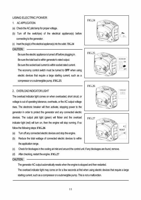
(c) Insert the plug(s) of the electrical appliance(s) into the outlet. FIG.24
CAUTION:
Be sure the electric appliance is turned off before plugging in.
Be sure the total load is within generator’s rated output.
Be sure the socket load current is within socket rated current.
The economy control switch must be turned to OFF when using
electric devices that require a large starting current, such as a
compressor or a submergible pump. FIG.25
2.OVERLOAD INDICATOR LIGHT
The overload indicator light comes on when overloaded, short circuit, or
voltage is out of operating tolerance, overheats, or the AC output voltage
rises. The electronic breaker will then activate, stopping power to the
generator in order to protect the generator and any connected electric
devices. The output pilot light (green) will flicker and the overload
indicator light (red) will turn on, then the engine will stop running. If so
follow the following steps: FIG.26
(a) Turn off any connected electric devices and stop the engine.
(b) Reduce the total wattage of connected electric devices to within
the application range.
(c) Check for blockages in the cooling air inlet and around the control unit. If any blockages are found, remove.
(d) After checking, restart the engine. FIG.27
CAUTION:
The generator AC output automatically resets when the engine is stopped and then restarted.
The overload indicator light may come on for a few seconds at first when using electric devices that require a large
starting current, such as a compressor or a submergible pump. This is not a malfunction.
FIG.24
FIG.25
FIG.27
FIG.26
ECON.SW
ON
OFF
OVERLOAD
RESET

12
3. DC APPLICATION (option)
This applies to 12V battery charging only.
(a) Disconnect the leads for the battery.
Fully loosen the battery fluid filler cap.
Fill distilled water to the upper limit, if the battery fluid is low level.
Measure the specific gravity for the battery fluid by using the
hydrometer, and calculate the charging time according to the table
shown on right side.
The specific gravity for the fully charged battery shall be within 1.26
to 1.28. It is recommended to check every hour. FIG.28
(b) Connect the DC output socket and the battery terminals using the
charging leads. The leads must be connected making sure the (+)
and (-) are correct.FIG.29
CAUTION:
Be sure the economy control switch is turned OFF while charging
the battery.
FIG.28
3
2
1
CSp
ecifi
c gr
avity
20°
3. 47AH 20HR2. 35AH 20HR1. 30AH 20HRBattery capacity
chargong time Hr8 104 620
1.06
1.14
1.10
1.22
1.18
1.26
1.30Aim for specific gravity and charging time
FIG.29
13
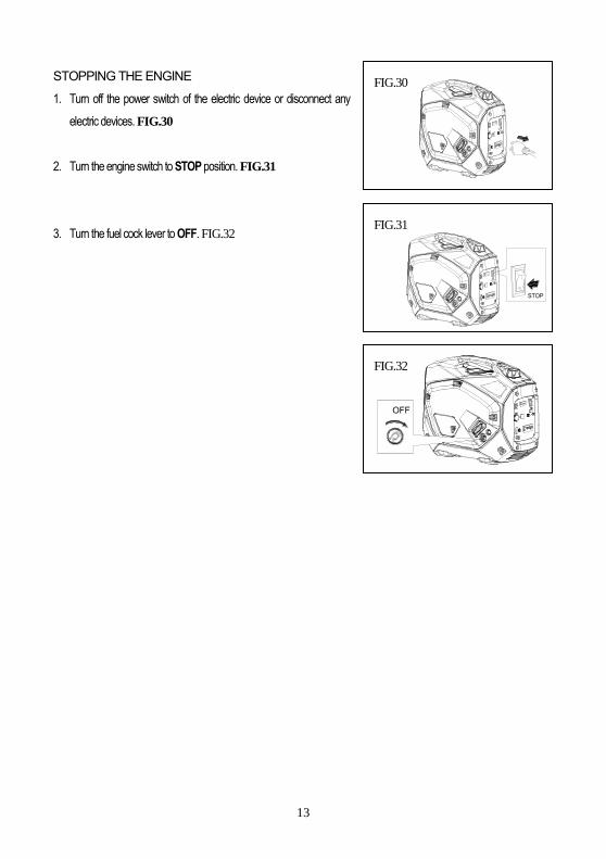
STOPPING THE ENGINE
1. Turn off the power switch of the electric device or disconnect any
electric devices. FIG.30
2. Turn the engine switch to STOP position. FIG.31
3. Turn the fuel cock lever to OFF. FIG.32
FIG.31
FIG.30
FIG.32
STOP
OFF
14
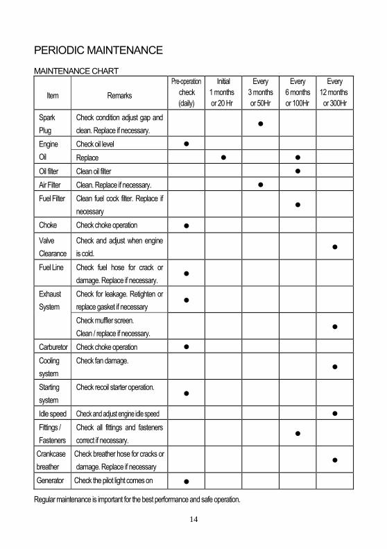
PERIODIC MAINTENANCE
MAINTENANCE CHART
Item Remarks
Pre-operation
check
(daily)
Initial
1 months
or 20 Hr
Every
3 months
or 50Hr
Every
6 months
or 100Hr
Every
12 months
or 300Hr
Spark
Plug
Check condition adjust gap and
clean. Replace if necessary.
Engine
Oil
Check oil level
Replace
Oil filter Clean oil filter
Air Filter Clean. Replace if necessary.
Fuel Filter Clean fuel cock filter. Replace if
necessary
Choke Check choke operation
Valve
Clearance
Check and adjust when engine
is cold.
Fuel Line Check fuel hose for crack or
damage. Replace if necessary.
Exhaust
System
Check for leakage. Retighten or
replace gasket if necessary
Check muffler screen.
Clean / replace if necessary.
Carburetor Check choke operation
Cooling
system
Check fan damage.
Starting
system
Check recoil starter operation.
Idle speed Check and adjust engine idle speed
Fittings /
Fasteners
Check all fittings and fasteners
correct if necessary.
Crankcase
breather
Check breather hose for cracks or
damage. Replace if necessary
Generator Check the pilot light comes on
Regular maintenance is important for the best performance and safe operation.

15
ENGINE OIL REPLACEMENT
1. Place the generator on a level surface and warm up the engine for
several minutes. Then stop the engine and turn the fuel cock knob
to OFF. Turn the fuel tank cap air vent knob counterclockwise to
the CLOSED position. FIG.33
2. Loosen the screw and remove the cover.
3. Remove the oil filler cap.
4. Place an oil pan under the engine. Tilt the generator to drain the oil
completely. FIG.34
5. Replace the generator on a level surface.
6. Add engine oil to the upper level. FIG.35
7. Replace the oil filler cap.
8. Replace the cover and tighten the screw
Recommended engine oil: (see page 19)
API Service “ SJ”
CAUTION:
Be sure no foreign material enters the crankcase.
Do not tilt the generator when adding engine oil. This could result in
overfilling and damage to the engine
AIR FILTER
Cleaning your air filter needs to be part of your maintenance regime. The
air filter ensures that the air entering the combustion chamber is as clean
as possible. Contaminated air wears on the engine caused by foreign
bodies and a less efficient combustion process. FIG.36
1. Remove the cover.
2. Remove the air filter cover and element.
3. Wash the element in solvent and dry.
4. Oil the element and squeeze out excess oil. The element should be
wet but not dripping.
5. Insert the element into the air filter.
6. Replace the cover.
FIG.33
FIG.34
FIG.35
FIG.36
16
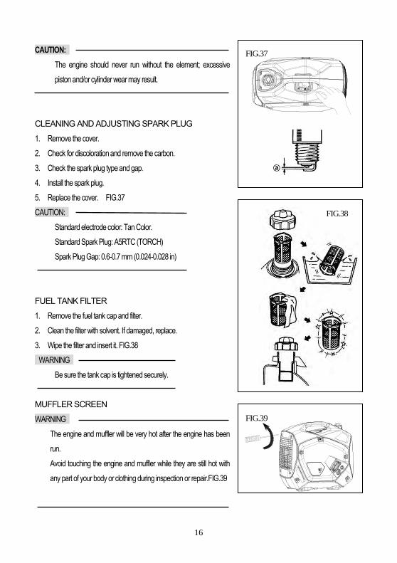
CAUTION:
The engine should never run without the element; excessive
piston and/or cylinder wear may result.
CLEANING AND ADJUSTING SPARK PLUG
1. Remove the cover.
2. Check for discoloration and remove the carbon.
3. Check the spark plug type and gap.
4. Install the spark plug.
5. Replace the cover. FIG.37
CAUTION:
Standard electrode color: Tan Color.
Standard Spark Plug: A5RTC (TORCH)
Spark Plug Gap: 0.6-0.7 mm (0.024-0.028 in)
FUEL TANK FILTER
1. Remove the fuel tank cap and filter.
2. Clean the filter with solvent. If damaged, replace.
3. Wipe the filter and insert it. FIG.38
WARNING
Be sure the tank cap is tightened securely.
MUFFLER SCREEN
WARNING
The engine and muffler will be very hot after the engine has been
run.
Avoid touching the engine and muffler while they are still hot with
any part of your body or clothing during inspection or repair.FIG.39
FIG.37
FIG.38
FIG.39

17
1. Remove the cover.
2. Remove the muffler screen.
3. Use a flathead screw driver to pry the spark arrester out from the
muffler.
4. Remove the carbon deposits on the muffler screen and spark
arrester using a wire brush.
5. Replace the muffler screen.
6. Replace the cover. FIG.40
TROUBLESHOOTING
Engine won’t start
1. Fuel systems
No fuel supplied to combustion chamber.
No fuel in tank….Supply fuel.
Fuel in tank….Turn fuel cock knob to ON.
Clogged fuel line….Clean fuel line.
Clogged carburetor….Clean carburetor.
2. Engine oil system
Oil level is low….Add engine oil.
3. Electrical systems
Poor spark
Spark plug dirty with carbon or wet….Remove carbon or wipe spark plug dry.
Faulty ignition system….Consult dealer.
4. Compression insufficient
Worn out piston and cylinder….Consult dealer.
5. Generator won’t produce power
Safety device (AC) to “OFF” …Stop the engine, then restart.
Safety device (DC) to “OFF” …Press to reset the DC protector
FIG.40

18
STORAGE
Long term storage of your machine will require some preventative maintenance to guard against deterioration.
DRAIN THE FUEL
1. Remove the fuel tank cap, drain the fuel from the fuel tank.
2. Remove the cover, drain fuel from the carburetor by loosening the drain screw.
ENGINE
1. Remove the spark plug, pour in about one tablespoon of SAE 10W30 or 20W40 motor oil into the spark plug hole
and reinstall the spark plug.
2. Use the recoil starter to turn the engine over several times (with ignition off).
3. Pull the recoil starter until you feel compression.
4. Stop pulling.
5. Clean exterior of the generator and apply a rust inhibitor.
6. Store the generator in a dry, well-ventilated place, with the cover placed over it.
7. The generator must remain in a vertical position.
19
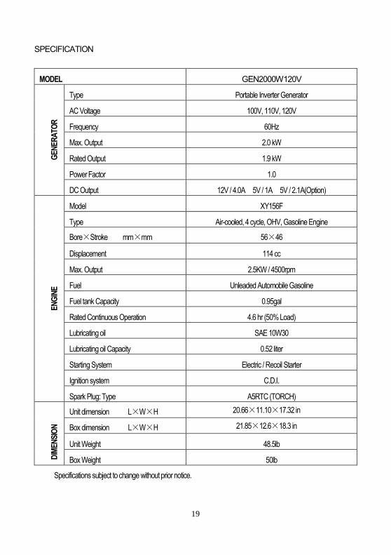
SPECIFICATION
MODEL GEN2000W120V
GE
NE
RA
TOR
Type Portable Inverter Generator
AC Voltage 100V, 110V, 120V
Frequency 60Hz
Max. Output 2.0 kW
Rated Output 1.9 kW
Power Factor 1.0
DC Output 12V / 4.0A 5V / 1A 5V / 2.1A(Option)
EN
GIN
E
Model XY156F
Type Air-cooled, 4 cycle, OHV, Gasoline Engine
Bore×Stroke mm×mm 56×46
Displacement 114 cc
Max. Output 2.5KW / 4500rpm
Fuel Unleaded Automobile Gasoline
Fuel tank Capacity 0.95gal
Rated Continuous Operation 4.6 hr (50% Load)
Lubricating oil SAE 10W30
Lubricating oil Capacity 0.52 liter
Starting System Electric / Recoil Starter
Ignition system C.D.I.
Spark Plug: Type A5RTC (TORCH)
DIM
EN
SIO
N
Unit dimension L×W×H 20.66×11.10×17.32 in
Box dimension L×W×H 21.85×12.6×18.3 in
Unit Weight 48.5lb
Box Weight 50lb
Specifications subject to change without prior notice.

20
WIRING DIAGRAM
INVERTERUNIT
OVERLOAD
LOW OIL
RPI
BLBRGR
P
Y/GW
OR
BU
OUTPUT
R
IGNITIONWINDING
OIL
SEN
SOR
SPAR
K PL
UG
SPR
ING
WIN
DIN
G
BATTERY
START MOTOR
CONTROL PANEL BLOCKGENERATOR BLOCK
ENGINE BLOCK
ELE
VALV
E
ELECTRIC MAGNET
ELECTRIC LOCK
IGNITION CONTROLLER
ECO. SWITCH
STEPPER MOTOR ASSY.
GRAY
BLACK / WHITE
PI
Gr
PINK
BL/W
ORANGEOW WHITE
P PURPLE
WBL P
W
IGN
ITIO
N C
OIL
BL O
R Y/G
P
GrR
BL
R
Y/G
FUSE 5A
OY W RBL
OR
YW
BL
Bu
YELLOW / GREENY/G
DCWINDING
GROUNDTERMINAL
Bu
Bu RECTIFIER
DC 12V OUTPUT
R
DC PROTECTOR 6A
RBL
BL
Bu
Bu
DC 5V OUTPUT
BL
W
Y/G
AC OUTPUT
RBU
OUTPUT RESET
BL
BL
BL
W
WSUBWINDING
MAINWINDING
FUSE 15A
RBL EC5
RBL
YELLOWY
BLBu
BLACKBLUE
G GREEN BROWN
RED
Br
R
M
R O Bu PI Br
AC PROTECTOR 20A
R
AUTO GENSTART