
PORTABLE HYDRAULIC - Defense Technical Information Center · PORTABLE HYDRAULIC POWER SOURCE ......
47
AD-A235 557 R-934 March 1991 N GE L By Nate Sinclair Sponsored By Naval Facilities Technical Report Engineering Command PORTABLE HYDRAULIC POWER SOURCE ABSTRACT The Naval Civil Engineering Laboratory (NCEL) has developed a Portable Hydraulic Power Source (PHPS) designed to en- able the Naval Construction Divers to operate oil hydraulic tools in an Arctic environment. The PHPS is a three-piece assembly developed to be lightweight, mobile, and capable of powering hydraulic tools through a 250-foot hose. It can be handled manually by four personnel, trans- ported in a small aircraft, and operated from a 22-foot inflatable boat. The PHPS can start at -40'F and supply 8 gpm of hydraulic fluid at 2,000 psi. This report describes the system, the approach used in developing the system, and the results of performance and reliability testing. NAVAL CIVIL ENGINEERING LABORATORY PORT HUENEME CALIFORNIA 93043-5003 Approved for pubic release; distribution unlimited. 9 1 5 0 9 (9 -
Transcript of PORTABLE HYDRAULIC - Defense Technical Information Center · PORTABLE HYDRAULIC POWER SOURCE ......

AD-A235 557 R-934
March 1991
N GE L By Nate Sinclair
Sponsored By Naval FacilitiesTechnical Report Engineering Command
PORTABLE HYDRAULICPOWER SOURCE
ABSTRACT The Naval Civil Engineering Laboratory (NCEL) hasdeveloped a Portable Hydraulic Power Source (PHPS) designed to en-able the Naval Construction Divers to operate oil hydraulic tools in anArctic environment. The PHPS is a three-piece assembly developed tobe lightweight, mobile, and capable of powering hydraulic tools througha 250-foot hose. It can be handled manually by four personnel, trans-ported in a small aircraft, and operated from a 22-foot inflatable boat.The PHPS can start at -40'F and supply 8 gpm of hydraulic fluid at2,000 psi. This report describes the system, the approach used indeveloping the system, and the results of performance and reliabilitytesting.
NAVAL CIVIL ENGINEERING LABORATORY PORT HUENEME CALIFORNIA 93043-5003
Approved for pubic release; distribution unlimited. 9 1 5 0 9 (9 -

~0
c, C c
-o M . -
.0 6 f 0) 0 .,0C,'
'C, wc)w.-o I _
4U L 0
2 -jco, o 0
Z C)
x t E~E 0
[L E11 L B LU
E ~~~ EE~~o a
0 10
- 0)
Po
.0 LU L
E E E)( LU - -o EN 0~' EC 0
.zZZ 1 OZ 91 J9LO O 1N C L 0)0 it o z i
Jill~~ ~~ 11 116 11LOL I 1 11 1 1111111 il i
E EEE EN 4, 4, 0)
> 4 .u u. EE EC~ 8
,- 0

Public reporting burden for this collection of Information is eatinated to average 1 hour per response, Including the time for reviewing Instructions, searching existing data sources,gathering and maintaining the data needed, and completing and reviewing the collection of information. Send commnts regarding this burden estimate or any other aspect of thiscollection information, Including suggestions forreducing this burden, to Washington Headquarters Services, Directorate for Information and Reports, 1215 Jefferson Davis Highway,Suite 1204. Arlington. VA 22202-4302, and to the Office of Management and Budget, Paperwork Reduction Prooec (0704-0 18), Washington, DC 20503.
1. AGENCY USE ONLY (Leave blank) 2. REPORT DATE &. REPORT TYPE AND DATES COVERED
I Marc 1991Final - FY88 to FY91
4. TITLE AND SUBTITLE &. FUNDING NUMBERS
PORTABLE HYDRAULIC POWER SOURCE____________________________________ PR - Y1606-16
SAUTHORIS) WU - DN387346
Nate Sinclair
7. PERFORMING ORGANIZAION NAME(S) AND ADORESSE(S) S. PERFORMING ORGANIZATIONREPORT NUMBER
Naval Civil Engineering Laboratory TR - 934Port Hueneme, CA 93043-5003
9. SPONSCRINGNAONITORING AGENCY NAME(S) AND ADDRESSE(S) 10. SPONSOANNGMONITOANNGAGENCY REPORT NUMBER
Naval Facilities Engineering CommandAlexandria, Virginia 22332
11. SUPPLEMENTARY NOTES
12i. DISTIBION/AVAILAWLUTY STATEMENT [Mb DISTIBUTION CODE
Approved for public release; distribution unlimited.I
13. AS3TRACT (Mazkn un200 words)
The Naval Civil Engineering Laboratory (NCEL) has developed a Portable Hydraulic Power Source(PHPS) designed to enable the Naval Construction Divers to operate oil hydraulic tools in an Arctic environ-ment. The P1-lPS is a three-piece assembly developed to be lightweight, mobile, and capable of poweringhydraulic tools through a 250-foot hose. It can be handled manually by four personnel, transported in a smallaircraft, and operated from a 22-foot inflatable boat. The PHPS can start at -40*F and supply 8 gprn of hydrati-lic fluid at 2,000 psi. This report describes the system, the approach used in developing the system, and theresults of performance and reliability testing.
14l. SUBJECT TERMS I&. NUMBER OF PAGES
Hydraulic power, Arctic, portable, diver tools, underwater construction 53I&. PRICE CODE
11. SECURI Y CLASSIFCATION 11S1. SECUUFTY CLASSUFICATMO lie. SECURITY CLASSIFCATION 20L LIMITATION OF ABSTRACTOf REPORT OF Th41S PAGE OF ABSTRACT
Unclassified Unclassified Unclassified UL
NSN 7540-01-280-5500 Stand~ ird Form 298 (Rev 2 A9PTre-*vid by ANSI 1;1d 239 18296-102

CONTENTS
Page
INTRODUCTION ..................................................... I
BACKGROUND ....................................................... I
SYSTEM DESIGN .................................................... 3
SYSTEM DESCRIPTION ............................................... 6
TEST ING .......................................................... 8
EVALUATION ....................................................... 13
Re liab ility ................................................. 16Logistic Supportability ..................................... 17
D ISCUSSION ....................................................... 18
RECOMMENDATIONS .................................................. 20
BIBLIOGRAPHY ...................................................... 20
APPENDIXES
A - Advanced Development Model Testing ...................... A-IB - Schematics: Hydraulic and Electric ..................... B-1C - Operating Procedures .................................... C-1
- ! T A
NAIA r. &i
v I ,
v - . . ,

INTRODUCTION
The Underwater Construction Teams (UCTs) need a hydraulic powerunit for operations in Arctic environments (-40'F). This unit must besimple, rugged, and mobile.
The Naval Civil Engineering Laboratory (NCEL) was tasked by theNaval Facilities Engineering Command (NAVFAC) to design, fabricate,test, and evaluate a Portable Hydraulic Power Source (PHPS). Thishydraulic power unit must be capable of powering any of the oilhydraulic tools used by the UCTs in extremely cold environments. Theunit must be man portable, and transportable in a Twin Otter aircraft.
This hydraulic power source was developed at NCEL as a mobile,self-contained assembly capable of operating in Arctic climates. Itprovides up to 8 gpm of flow at 2,000 psi to power hydraulic toolsthrough 250 feet of hose. This system was designed as a modularizedassembly to accommodate ease of handling and to fit into small aircraft.
This report describes the overall development of the PHPS. Thetesting and evaluation described in this report pertains to theEngineering Development Model (EDM). The testing performed on theAdvanced Development Model (ADM) can be found in Appendix A of thisreport. The development of the PHPS consisted of designing and testingprototype units. The results from these efforts were then used todevelop an Operation and Maintenance (O&M) Manual and a PurchaseDescription package, complete with a level 3 drawing package of thefinal production unit.
BACKGROUND
The Underwater Construction Teams presently have three oilhydraulic power sources available to power their tools. These unitshave the following characteristics:
Maximum Flow Maximum PressureModel No. Weight (lb) gpm_ (psi)
MOD 2 1,000 15 2,000MOD 3 420 7 1,500MOD 7 250 10 2,000
The Naval Sea Systems Command (NAVSEA) MOD 2 has sufficient powerto drive any twu UCT hydraulic tools, but is too heavy to be man por-table. The NAVSEA MOD 3 is portahle, ,ut t powc;-r'f -ruq1' tc, driveLUe UCT rock drill. [he NAVSEA MOD 7 is sufficiently portable and
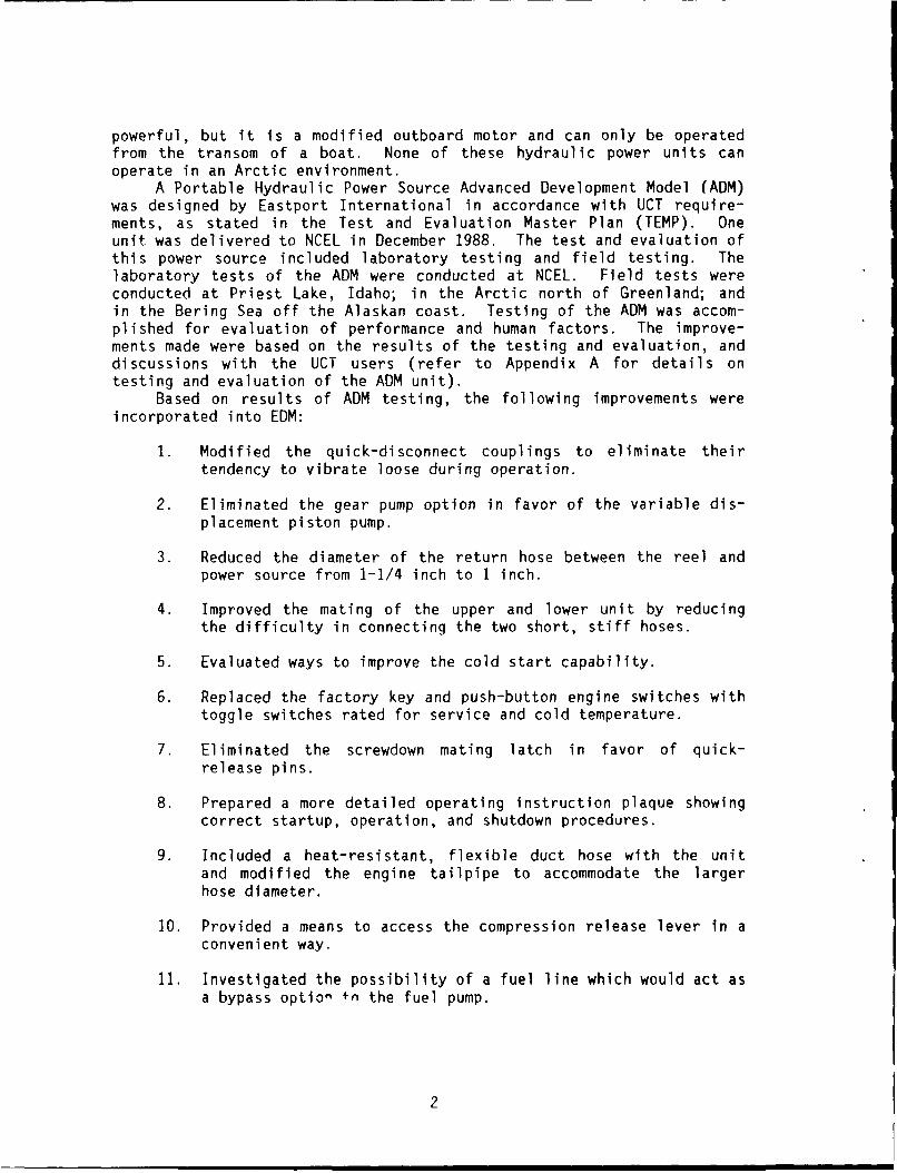
powerful, but it is a modified outboard motor and can only be operatedfrom the transom of a boat. None of these hydraulic power units canoperate in an Arctic environment.
A Portable Hydraulic Power Source Advanced Development Model (ADM)was designed by Eastport International in accordance with UCT require-ments, as stated in the Test and Evaluation Master Plan (TEMP). Oneunit was delivered to NCEL in December 1988. The test and evaluation ofthis power source included laboratory testing and field testing. Thelaboratory tests of the ADM were conducted at NCEL. Field tests wereconducted at Priest Lake, Idaho; in the Arctic north of Greenland; andin the Bering Sea off the Alaskan coast. Testing of the ADM was accom-plished for evaluation of performance and human factors. The improve-ments made were based on the results of the testing and evaluation, anddiscussions with the UCT users (refer to Appendix A for details ontesting and evaluation of the ADM unit).
Based on results of ADM testing, the following improvements wereincorporated into EDM:
1. Modified the quick-disconnect couplings to eliminate theirtendency to vibrate loose during operation.
2. Eliminated the gear pump option in favor of the variable dis-placement piston pump.
3. Reduced the diameter of the return hose between the reel andpower source from 1-1/4 inch to I inch.
4. Improved the mating of the upper and lower unit by reducingthe difficulty in connecting the two short, stiff hoses.
5. Evaluated ways to improve the cold start capability.
6. Replaced the factory key and push-button engine switches withtoggle switches rated for service and cold temperature.
7. Eliminated the screwdown mating latch in favor of quick-release pins.
8. Prepared a more detailed operating instruction plaque showingcorrect startup, operation, and shutdown procedures.
9. Included a heat-resistant, flexible duct hose with the unitand modified the engine tailpipe to accommodate the largerhose diameter.
10. Provided a means to access the compression release lever in aconvenient way.
11. Investigated the possibility of a fuel line which would act asa bypass option fn the fuel pump.
2

12. Identified alternate construction to reduce the weight of the
hose reel.
13. Provided the unit with lifting points and tiedown points.
14. Sealed all reservoirs to allow the power source to be filledwith fluids during transportion.
i5. Ensured that the oil pressure gauge is protected from fallingobjects, etc.
16. Located the flow valve on the downstream side of the pressurerelief valve.
17. Removed all sharp edges from the power unit and hose reel.
18. Added a fuel pump to the spare parts list.
Two Portable Hydraulic Power Source EDMs were fabricated, and de-livered to NCEL in January 1990.
SYSTEM DESIGN
The Portable Hydraulic Power Source is required to meet the thres-holds specified in the "Arctic Tools and Techniques Test and EvaluationMaster Plan (TEMP)." Table 1 describes the TEMP requirements.
The PHPS must be capable of powering any one of the UCT hydraulictools. The unit is required to operate in Arctic conditions. The sizeand weight of power source unit is constrained so that all of its com-ponents will fit inside a small aircraft, and be readily moved by fourpersonnel.
To ensure that the PHPS will be capable of driving any one of theUCT hydraulic tools, the hydraulic power output of the power source wasmatched to the hydraulic requirements of the Stanley Tool HD-20 rock-drill. The HD-20 rockdrill is the UCT's most demanding hydraulic tool.Manufacturer's recommendations, and experience in the field, indicatethe need for a hydraulic fluid flow of 8 gpm at 2,000 psi to properlypower this rockdrill. Nine different diesel engines were researched forincorporation into the hydraulic power source. Table 2 lists thesevarious diesel engines and their characteristics. It was determinedthat the Lomabardini diesel engine best meets the system requirements.This engine provides the required horsepower, is lightweight, and hasrelatively low noise output. The Lombardini is also equipped with com-pression release levers to allow easier cranking when cold.
3

Table 1. TEMP Requirements
Parameter Requirement
Power Source Operate at leastPerformance one tool
Operating Temperature -40 to 60(OF)
Storage Temperature -60 to 150(OF)
Operating Wind Speed 15 knots
Maximum Size yes(must fit into Twin Otter)
Maximum Single 400Component Weight (lb)
MTBF (hr) 67(Mean Time Between Failure)
MTTR (hr) 2(Mean Time To Repair)
Minimum Reliability 0.90(for 7-hour mission)
Minimum Availability 0.90
Maximum Maintenance (hr)Daily 2End-of-Project 16Annually 8
Useful Life (yr) 7
4

-0 0 ) '4
CCoo 0 4
J 4 .J - 4 4 i -00 C) to0 0a0 c :3 LS- kA W4-'4- 4
CD0 - C 00 -e _Au _r E W in)i Ct6Aai- WI tn 4 L1. n +) u.- toWZ) 0
-. C (a W 0) 2D > a~+ W. )4-)E4A 4-) 40 -. iC = IA -C 0L-- 0 00a.- '- CA
4-' 4J D to 4 +) 4-) 4J 4J S-0c - ~ a, >, -C g 0-i o) rc C c CA :) - nU s- >(D ~ c oW Od) 0)C-'- 0). -Ci4A- 5-.- 42= X - oC> .- C > a)C 0 a)>4- C .-E %A C 'a0 LnO0.- LAO0.- *'--)5-4 0 0) OW'-- JZ0 0L -V0 S-0M> S- CL> Mo S- CLd S.W 5-- - 4-) 0-C-) -:0 o )25= - (D 5- : s- ) CL 06 C) - in to
CD U w >0o : > 0 : -) W m 4J)i CA kn.0 4-A0C U Uin u i t 0 aC C M -C-.- a) L. 0LOW in4AC V3 V 0 0 W'4- :3-( * Cn I- -do
4 d) WU4-W W) L) 4J ccCr Q - .- 0 .- VU4C 0-0M4' 00-i 0 U. U.0 U '0 CLSO 4J) U C0-W oW0 E (UindW a)S. 4-)) U4) 00-. Xi *-W 0)o
4-) >0 Ww d)A jwi C u--) 0) '4- tM 3:a--i %A WW ) c- ) WO- - o > Ct -0>-, CC0 Va 0 -C $.- C 5-0V -0CAn S.) *.- to :- 0 S0 - VC : o 'VCa= 0 0 00 %n00 t 0- w Ln ME V) CLE ix <0 c LA S C 0+ CC 4J =4- 0 CCfV
0W 0-
ina, C1 k O CD CD C) C) C) W (100- V V 0 V0 V0 V0 V 0 V V V
0 'D (YI LO 00 CDj I,, -d- ko 00 inU D= D C CD CD C CD CD C) to
5_ -0 C
4-)
S- 0-C Ln LO LO L- 00 CD CO CN-L 4-)
to M5- - ON CD m CD en CDi Ci C CD to
Cl CCD 4 l l c ~ ~0
0) S)- C,
5-D *' :f CDL AL OCD L DL -c E.-.- I 01 D- 0 CD C) ) ) CD CsJ LA C) 00- CW'. 4 i CNJ CD C) C-D CN CDJ CNi CD
42 L.A L J o Ci ~0a 0 iniCj ~ l
CD CD CCCD)-0 inC ) CD C )C - Vt
C E~- Cn CD C D CCD CD C CD 'A(NW 0- W 0 C D D CD CD CD CDC
M '- E -CD C) C) -l C Ca)J X>C )- CL0 -0 ) l a 4 C r0 0- C
S-~~0 4- 4-1 zLo0 to CD CD CD CD C6 - r
OX CD C D -- - -t -I 4 -
WE0-~ ~~~ C') C
m~0 0)S-~~~~~~4 C) V nL ~ L 3r
o) ) C C )L nLA .40 00 CA 1-' m- mO CDWWW2C 4'D EC DCiII Nd 4) ivo - U') CA LA LA e-J u. )-0 S
OD <D C3 mD LA LA LA CCLn
N-- Of oc C C (j CD ~ 4-' 41'LA.I mD mDCD F- .-4 LA- (NJ U .0dd)W
to 0 cc0W)0 *'- -- VC-
to Nt N) W )0)0 N C CC) 0) .0 4-) NV0-
LLJ : 0o -T , W WO
V)~~~~C C) -f ) C i C
0) 4 CD in4n OD(JI)LA I -C -0>) L.) <CDm
5

The design of this power source emphasizes the ability to withstandstorage at -60*F, and to operate at -40'F. The wires, hoses, and fit-tings on the unit are all specified to withstand temperatures down to-60'F. Electric preheaters are installed in the unit for startup andoperation at temperatures down to -40*F. These are powered by anexternal source of 120-VAC electricity. Two hydraulic fluids, bothmanufactured by Aerospace Lubricants Incorporated, provide the desiredviscosity at ambient temperatures between -40 and 60'F. The hydraulictools require fluid with a kinematic viscosity range of 20 to 80 centi-stokes. Tribolube L-6 is suitable for use between -40 and 32*F ambientair temperature (fluid temperature of 0 to 60'F). Tribolube L-1 is usedfor ambient temperatures above 32'F (fluid temperature of 60 to 135F)(see Figure I for the viscosity versus temperature chart for these twofluids). Arctic Diesel Fuel (DFA) or JP-5 fuel is required to run thediesel engine under Arctic conditions. These fuels contain little waxor water, thus preventing them from solidifying at -40'F. For this samereason, synthetic motor oil is needed for the engine.
For ease of handling, the PHPS is designed as three individualcomponents. These components are transported separately, and thenjoined together to form the power source. This configuration wasselected to meet the size and weight constraints which allow the systemto be handled by personnel, and enable it to fit inside small aircraft.
SYSTEM DESCRIPTION
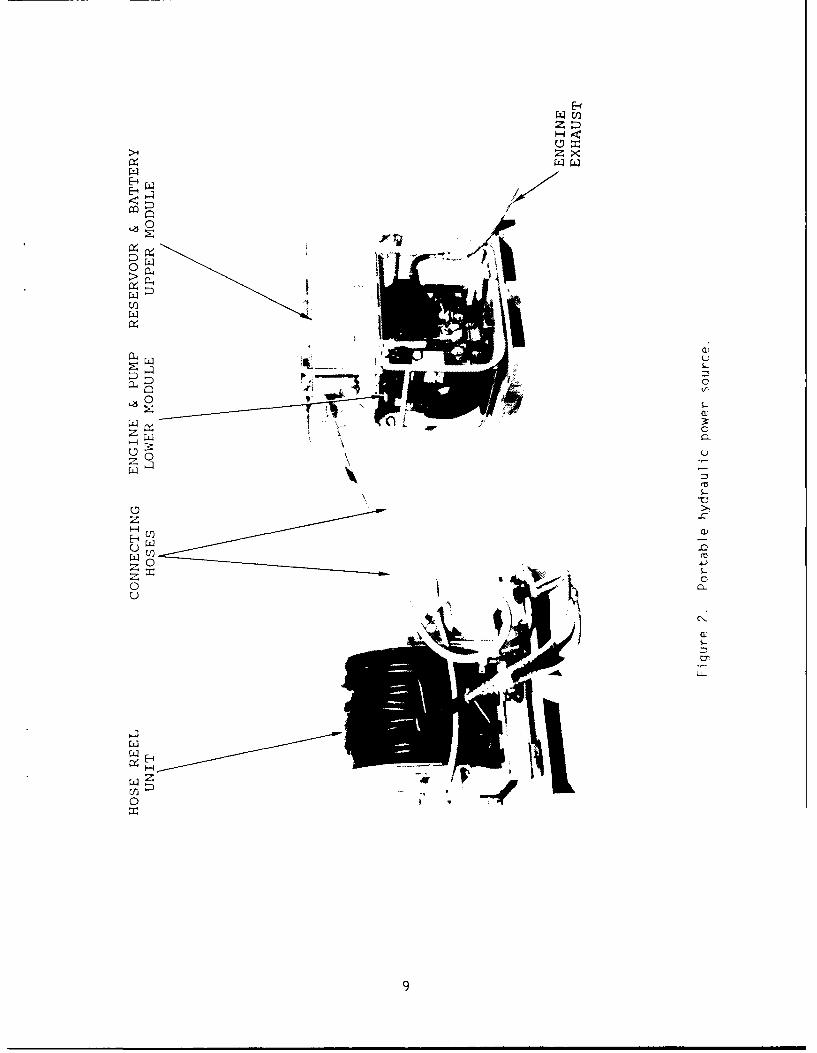
The Portable Hydraulic Power Source is a modularized assembly con-sistino of three basic components: (1) a lower engine/pump module, (2)an upper reservoir module, and (3) a hose reel. These power unitmodules are designed to be quick and easy to set up in the field.
The engine/pump module is enclosed in an aluminum frame that is 36inches long by 23 inches wide by 28 inches high. This module weighs 325pounds and is configured with four lifting handles, as well as fourlifting/tiedown provisions. The prime mover and the hydraulic pump arehoused in this lower module. The prime mover is an 18-horsepower, two-cylinder, Lombardini diesel engine. Two glow plugs ire mounted in theengine inlet air manifold, one over each cylinder, that provide greaterpreheating of the inlet air. The engine is started electrically bymeans of a 12-volt battery integral to the system. The hydraulic pumpis a variable displacement, axial piston pump. The variable displace-ment characteristic of the pump allows the engine to be started with nohydraulic load.
The reservoir module frame measures 35 inches long by 20 incheswide by 16 inches high. This upper module consists mainly of a 5-gallonhydraulic oil reservoir and a battery box. This module weighs 145pounds with the battery and hydraulic fluid. The battery used is amarine/RV gel-cell battery with a 700 cold cranking amps rating. Thegel-cell construction provides high recovery capability from deep dis-charge, as well as a leakproof feature that allows the battery tco beshipped without special considerations.
6

VISCOSITY VS. TEMP. FOR TRIBOLUBE L-6 AND L-1
(DEGREES F. VS. CENTISTOKES)
235 FR
I A
135 0
HYDRAULIC -- IFLUID---
TEMPERATURE __
70 L- [
1 4 . -N
-- 10 100 1000 -10000
19.8 82
HYDRAULIC FLUID VISCOSITY
Figure 1. Hydraulic fluid viscosity versus temperature.
7

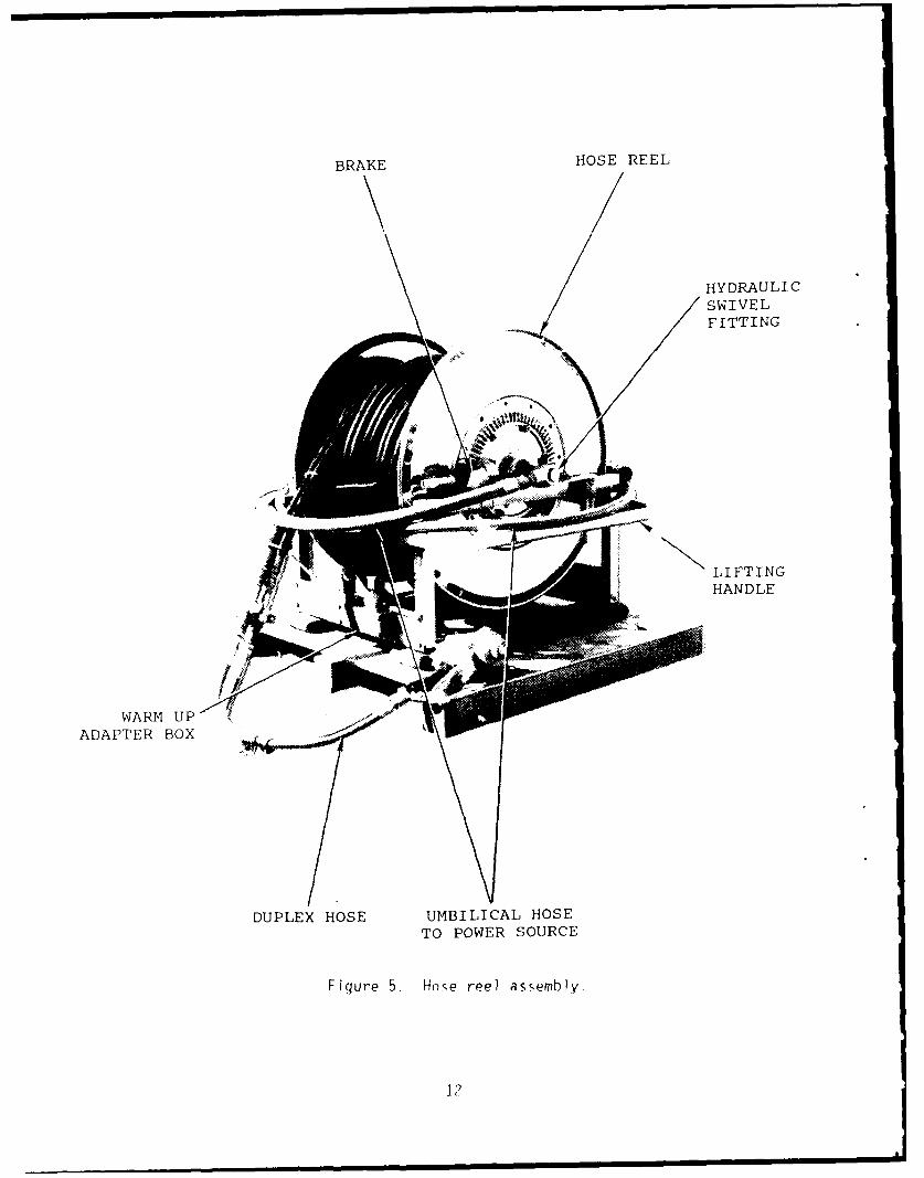
The portable hose reel measures 33 inches lonq by 33 inches wide by34 inches high. It holds 250 feet of 3/4-inch tandem hose and weighs365 pounds with the hose filled with oil. A single length of tandemhose delivers the oil to the tool and returns it to the power unit.
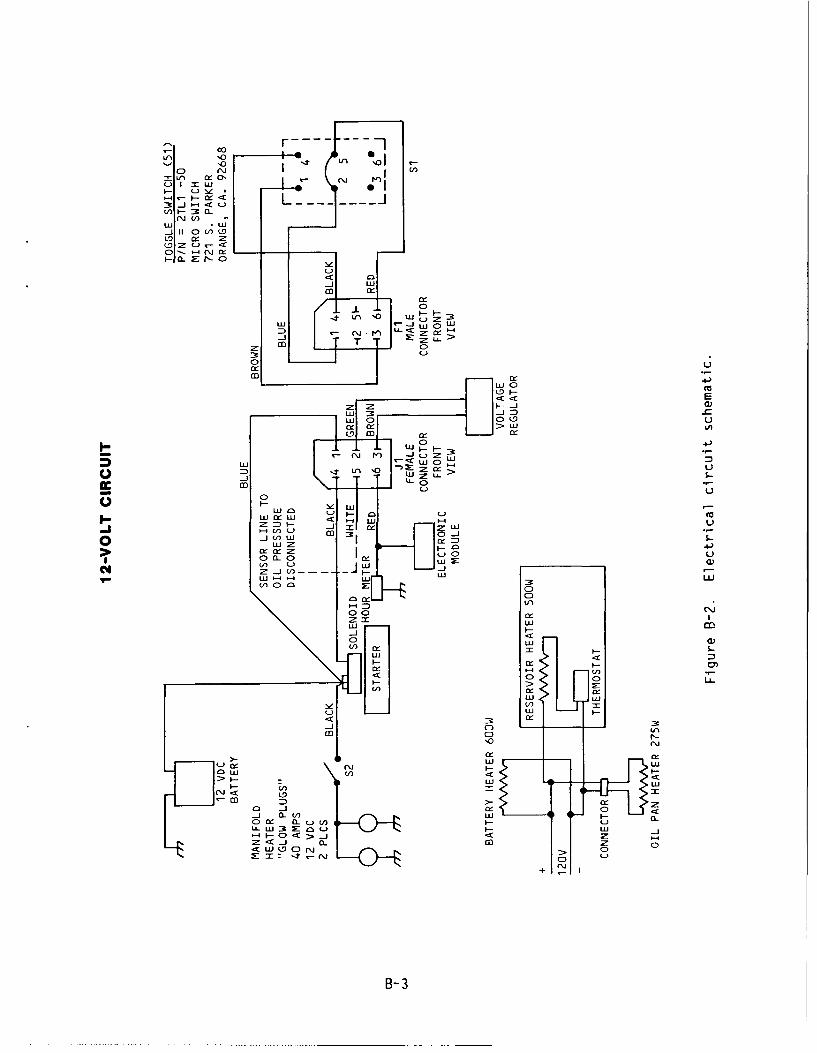
System preheaters are incorporated for operation in extremely lowtempt-atures. These preheaters are located in the engine oil sump, thehydraulic fluid reservoir, and in the battery enclosure. These arepowered by an external source of 120-VAC electricity. Appendix B showsthe system electrical schematic, inclling the 120-VAC system preheatercircuit and the 12-VOC engine circuit. Figures 2 through 5 sh3w thevarious features of the Portable Hydraulic Power Source.
TESTING
Two EDM power sources were subjected to performance testing ig theNCEL cold chamber facility. R th units were then subjected to develop-ment testing and user testing in an Eastern Arctic field operation. Oneof the EDM power sources, Unit No. 1, was also subjected to endurancetesting at NCEL in order to complete the reliability testing that beganin the Arctic.
Both Portable Hydraulic Power Source EDMs were tzsted in the NCELcold chamber facilities to evaluate system performance at extreme tem-peratures. This testing was accomplished in February 1990.
The modular components of both units wre separated and placed inthe cold chamber at -55°F for 16 hours. Both units were assembled with-out difficulty. To make the hydraulic connection te'ween the upper andlower modiles, the upper module was tilted in o'der to .--duce the anglerequired for bending the two hoses into positior.
The power sources were subsequently cold-soked overnight at -40'F.Preheat was applied to one unit for 30 minutes. At this )oint, threeattempts were made to start the engine. The glow plugs w-re applied for30 seconds the first try, 60 seconds the second try, and '10 seconds thethird try. Att2mpts to start the unit at this point were (bandoned whenits battery began to run down. This unit was then preheated for anadditional 30 minutes. After this, the glow plugs were applied for 3flseconds, the engine started, sputtered for about 15 seconds, then quit.This continued for six attempts. Toe engine was finally started byturning the engine on while holding the glow plug on and priming theengine fuel pump. After 2 minutes of running, the pump was adjusted tofull flow. The power source was then run at 8 gpm and 2,000 psi. Atthis point, the unit was performing well, so the testing was stopped.
After cold-soaking for 60 hours at -40'F, the second unit startedwith 1 hour of preheat time. The engine initially ran very rough andcycled up and down at a slow speea. The glow plugs were kept on untilthe engine started to run normally (20 seconds). lhe unit was run fur10 minute-, at pressures up to 2 fno psi. This cold chamber testingdemonstrated that both Portablr. Hydraulic Power Source EDM units havethe capability to startup and rperate in an Arctic climate.
8
UU
E-S.
<C
0x
'-4k
-4
"- 1 44
0

HYDRAULIC FLUID BATTERYRESERVOIR TANK BOX
STOPLEVER
, i PUMP
M U F F LE R
n~ T T
D IP sTICK
HYDRAULIC
THROTTLETREL~VER
OIL ENGINEDRAIN VALVE EXHAUST
Figure 3. Upper reservoir module mounted on lower engine/pump
module, front view.
10

ELECTRICAL PREHEATERBATTERY JUNCTION BOX HYDRAULIC HYDRAULIC
BOX FLUID FILTER FLUID TANK
FL E LTAN K
LI FTI NGLIFT/ HIANDLES
TIEDOWNPROVISION
FUELFT I TER.INSIDE DIESELTANK ENGINE
ENGINESTARTER
HYDRAULIC BATTERY CRANKCASE ENGINE
FLUID PUMP CABLE HEATER OIL FILTER
Fiqure 4. Upper reservoir module mounted on lower engine/pump
module, rear view.
11
BRAKE HOSE REEL
HYDRAULICSWIVELFITTING
/N
LIFTINGHANDLE
WARM UP i
ADAPTER BOX
DUPLEX HOSE UMBILICAL HOSETO POWER SOURCE
Fiqure 5. Hose reel assembly.
P?

Both PHPSs were shipped to a field operation in the Eastern Arcticin March 1990 for development testing and user testing. They operatedfor 2 weeks in temperatures down to -25*F. Unit No. I was subjected toendurance testing in order to obtain reliability data. It was testedfor 7 days. The unit was preheated for 1 hour before each start.Startups were accomplished with no problem. The power source was typ-ically operated for 4 hours in the morning and 4 hours in the afternoon.The unit ran at 6 to 8 gpm with pressure averaging 800 psi. EDM UnitNo. 1 accumulated 45 hours of run time with no failures.
Unit No. 2 was used for operational testing with hydraulic tools.During the 8 days that Unit No. 2 was operated, three problems wereobserved. First, the fitting below a high-pressure quick-disconnect(Q/D) failed. This was due to the Q/D not having been secured, andvibrating loose. The fitting took 45 minutes to repair. Second, at onepoint the battery was not energizing the engine starter sufficiently.It was discovered that the battery cable connectors between the upperand lower module had become severely corroded. These were then cleanedand reconnected, which fixed the problem. Third, this unit was observedto blow oil out of the exhaust. Evidently, this was caused by insuffi-cient break-in of the engine. Synthetic oil works so well, valves willtake longer to seat properly when synthetic motor oil is used to breakthe engine in. EDM Unit No. 2 ran for 24 hours without any failuresafter the repairs were made.
Both EDM units started whenever required, and provided the neces-sary hydraulic power. Comments were made by the UCTs that the top andbottom modules were still somewhat difficult to connect at these extremetemperatures, and that the system needs a greater fuel storage capacity.
Upon return to NCEL, the Portable Hydraulic Power Source EDM UnitNo. 1 was subjected to further long-term operation. EDM Unit No. 1 wasfabricated from system components taken from the ADM unit, and used todemonstrate overall system reliability of the PHPS. This reliabilitytesting consisted of accumulating operating hours on the power source byrunning it for 6 hours a day. The unit was started and stopped twice aday. The power source was fueled from an outside jerry can throughoutthe course of this testing. This power source was run at 2,000 psi and6 gpm. The duplex hose was submerged in the NCEL dive tank to keep thesystem temperature down. The hydraulic oil temperature remained at110'F during testing. The Portable Hydraulic Power Source EDM UnitNo. 1 was operated at NCEL for 58 hours with no failures.
Table 3 summarizes the malfunctions encountered during all thereliability testing performed on the Portable Hydraulic Power Source ADMand EDM Unit No. 1.
Testing on the PHPS was completed in August 1990. The operatingprocedures developed during testing are shown in Appendix C.
EVALUATION
Both Portable Hydraulic Power Source EDM units met the requirementfor starting at -40*F. This required I hour of preheat time. Thesepower sources also met the performance requirement (8 gpm at 2,000 psi)when operating in the cold chamber.
13

Table 3. Malfunctions Observed During Reliability Testing on Unit No. I
Hourson Unit Malfunction Cause Remedy
Eastern Arctic, 1989
0 Begin testing
27 Engine would not start Frozen fuel Use DFA or JP-5 fuelat -20OF
27 Starter switch would Switch not rated for Rewire switch usingdelay 5 to 8 seconds extremely low components rated forat -20°F temperatures extremely low
temperatures
35 Overflow of hydraulic Pump inlet Q/D Modify Q/Dfluid had backed off connectors
40 Engine quit, fuel Ice blockage in fuel Develop preventativespitting from fuel filter, and breather/ maintenancepump separator hose procedures
44 Engine quit Broken diaphragm Supply spare fuel
retainer in fuel pump pump
44 End testing
Western Arctic, 1989
44 Begin testing
49 Engine stalled Pump outlet Q/D Modify Q/D(flow meter stuck at had backed off connectors6 gpm)
51 End testing
Eastern Arctic, 1990
51 Begin testing
80 Pump swashplate Both retaining screws Reinsert andfell off vibrated loose retighten screws
81 Pump swashplate Both retaining screws Reinsert andfell off vibrated loose retighten screws
94 End testing
continued
14

Table 3. Continued
Hourson Unit Malfuntion Cause Remedy
NCEL, 1990
94 Begin testing
117 Engine sump leaks Fitting for heater Replace any missingslightly element leaked and oil
could not be re-tightened fromoutside
147 Pump limit screw Screw vibrated loose Reinsert andfell out retighten screw
151 Pump suction collar Retaining screws Reinsert andcame loose vibrated loose retighten screws
154 End testing
The deficiencies encountered during testing can be solved with rela-tively minor changes to the unit design and its operating procedures.One comment from the operators in the field was that the frequent re-fueling requirement of the power source (approximately every 2 hours)was a major inconvenience. The capability to be fueled from an externaljerry can will be incorporated into the design to enable the PHPS tooperate for up to 8 hours without refueling. Comments were also madethat there is still some difficulty in connecting the upper module tothe lower module out in the field. The hose connections between theupper and lower module will be further modified to ease the difficultyassociated with manipulating hoses stiffened from the Arctic conditions.The hardware that vibrated loose was not properly secured. This will becorrected with the addition of simple locking devices to the design.Also, the battery cable design will be simplified into a more ruggedconfiguration.
The following modifications have been made to the PHPS design forincorporation into the final production units:
1. Provide capability to fuel the APS from an external jerry can.
2. Improve hose connectibility between upper and lower modules.Use a lower pressure, more flexible hose for pump inlet.Lengthen pump inlet hose by moving its connection on the res-ervoir. Add extra techniques on hose connection to the O&Mmanual.
15

3. Replace battery cable terminals with more rugged wing-nuttypes.
4. Eliminate the connectors on the battery cable (use a singlelength of electrical cable).
5. Mark flow meter to be read from both sides so the operator can
see the flow rate while adjusting the pump.
6. Label the warmup adaptor box on the hose reel.
7. Label the Q/D locking wing-nuts disconnect directions on thelower module connection plate.
8. Secure the retaining screws on the pump assembly to prevent
their vibrating loose.
9. Add the following instructions to the O&M manual:
a. Provide methods for easy connection of hoses between theupper and lower modules.
b. Give recommendation for engine break-in.
c. Check (and clean) electrical connectors periodically.
d. Keep glow plugs on during startup.
e. Secure Q/D wings together to prevent vibrating loose.
f. Provide operating temperature range of the hydraulic fluid.
These modifications will eliminate the shortcomings of the PortableHydraulic Power Source system identified during testing of the EDM unit.
Both EDM units performed well in a field operation in the EasternArctic. The Underwater Construction Team personnel were pleased withthe overall performance of the power sources, especially the ease ofstartup in Arctic conditions.
Reliability
A generally accepted definition of reliability is: the probabilitythat an item will perform its mission without failures for a specifiedperiod of time. The reliability definition for the Portable HydraulicPower Source has been derived from this general definition. Reliabilityis expressed mathematically as follows:
-tR = e
where: R = reliability (expressed as a decimal)e = base of the natural log system (2.718)t = mission time in hours= failure rate per million hours, or 1/MTBF
16

by substitution:
R = et/MTBF or MTBF = -t/in R
For a reliability of 0.90, the PHPS needs a Mean Time Between Fail-ure (MTBF) of 67 hours. This is for a mission time of 7 hours specifiedin the TEMP. The MTBF of 67 hours derived above represents an estimateof true system reliability. A confidence level is then applied as ameasure of the approximation of the estimated MTBF to the true value.Confidence levels are based on a Chi Square distribution. The PHPS mustrun for 154 hours without failure to achieve a confidence level of 90percent.
Failure is defined as any malfunction that the operator cannotremedy by adjustment, repair, or replacement action within the Mean TimeTo Repair (MTTR) using only controls, tools, or spare parts incorporatedin or carried with the system.
Unit No. 1, which was built from the original components used onthe ADM version, demonstrated system reliability by operating for therequired 154 hours with no failures. Given the definition of failureshown above, none of the malfunctions that occurred throughout thetesting on this unit are considered failures. Thus, the PHPS has demon-strated a reliability of 0.90 with a confidence level of 90 percent.
Inherent availability is expressed as a decimal and is caiculatedmathematically as follows:
A = MTBF/(MTBF+MTTR)
Given an MTBF of 67 hours and an MTTR of 2 hours, the inherentavailability is 0.97.
Logistic Supportability
The Portable Hydraulic Power Source is designed to be compatiblewith the UCT's operation and maintenance capabilities. Each unit willbe delivered to the user with an operation and maintenance kit, includ-ing replacement parts and regular maintenance parts. No special toolsare required to perform any of the maintenance outlined in the Operationand Maintenance Manual.
All spare parts will be transportable in a permanent storage case.The spare parts list is as follows:
Engine air filter ............................ 2 each
Engine oil filter ............................ 2 each
Fuel filter .................................. 2 each
Hydraulic fluid filter ....................... 2 each
Hydraulic oil, Tribolube L6 or Li ............ 5 gallons(oil selection is dependent ontemperature)
17
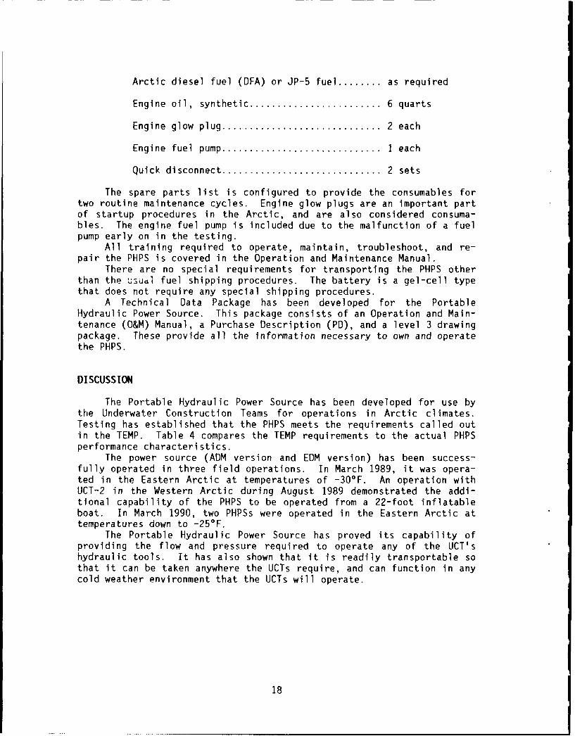
Arctic diesel fuel (DFA) or JP-5 fuel ........ as required
Engine oil, synthetic ........................ 6 quarts
Engine glow plug ............................. 2 each
Engine fuel pump ............................. I each
Quick disconnect ............................. 2 sets
The spare parts list is configured to provide the consumables fortwo routine maintenance cycles. Engine glow plugs are an important partof startup procedures in the Arctic, and are also considered consuma-bles. The engine fuel pump is included due to the malfunction of a fuelpump early on in the testing.
All training required to operate, maintain, troubleshoot, and re-pair the PHPS is covered in the Operation and Maintenance Manual.
There are no special requirements for transporting the PHPS otherthan the usual fuel shipping procedures. The battery is a gel-cell typethat does not require any special shipping procedures.
A Technical Data Package has been developed for the PortableHydraulic Power Source. This package consists of an Operation and Main-tenance (O&M) Manual, a Purchase Description (PD), and a level 3 drawingpackage. These provide all the information necessary to own and operatethe PHPS.
DISCUSSION
The Portable Hydraulic Power Source has been developed for use bythe Underwater Construction Teams for operations in Arctic climates.Testing has established that the PHPS meets the requirements called outin the TEMP. Table 4 compares the TEMP requirements to the actual PHPSperformance characteristics.
The power source (ADM version and EDM version) has been success-fully operated in three field operations. In March 1989, it was opera-ted in the Eastern Arctic at temperatures of -30'F. An operation withUCT-2 in the Western Arctic during August 1989 demonstrated the addi-tional capability of the PHPS to be operated from a 22-foot inflatableboat. In March 1990, two PHPSs were operated in the Eastern Arctic attemperatures down to -25'F.
The Portable Hydraulic Power Source has proved its capability ofproviding the flow and pressure required to operate any of the UCT'shydraulic tools. It has also shown that it is readily transportable sothat it can be taken anywhere the UCTs require, and can function in anycold weather environment that the UCTs will operate.
18

Table 4. TEMP Requirements Versus As-Built Characteristics
TEMP As-BuiltParameter Requirement Characteristics
Power Source Operate at least Operates the worst-Performance one tool case tool (rockdrill)
Operating Temperature -40 to 60 -40 to 80(OF)
Storage Temperature -60 to 150 -60 to a
(OF)
Operating Wind Speed 15 knots 20 knots
Maximum Size yes yes(must fit into Twin Otter)
Maximum Single 400 365Component Weight (lb)
MTBF (hr) 67 67(Mean Time Between Failure)
MTTR (hr) 2 2(Mean Time To Repair)
Minimum Reliability 0.90 0.90(for 7-hour mission)
Minimum Availability 0.90 0.97
Maximum Maintenance (hr)Daily 2 0.5End-of-Project 16 8Annually 8 8
Useful Life (yr) 7
aNot tested.Insufficient testing for high level of confidence.
19

RECONENDATIONS
Hydraulic power sources conforming to the specifications andd, awings produced under this development effort should be purchased tosupport the work performed by the U.S. Navy Underwater ConstructionTeams in Arctic areas.
In addition, hydraulic fluids with higher operating temperaturesshould be identified which will extend the operating environment of thispower source to include warm climates. This will enable the PortableHydraulic Power Source to meet the hydraulic power requirements for theUCTs in any environment.
BIBLIOGRAPHY
Barradas, S. (1987). Test and Evaluation Master Plan - Arctic Tools andTechniques. Naval Civil Engineering Laboratory, Port Hueneme, CA, Apr1987.
Barradas, S. (1989). Summary of Arctic Power Source Field Test (ArcticWest). Naval Civil Engineering Laboratory, Fort Hueneme, CA, Aug 1989.
Eastport International, Inc. (1988). Arctic Power Source. Marlboro,MD, Nov 1988.
Eastport International, Inc. (1989). Arctic Power Source Field TestResults. Marlboro, MD, Apr 1989.
Kunsemiller, J. (1989). Test Plan, Arctic Tool Power Source. NavalCivil Engineering Laboratory, Port Hueneme, CA, Jan 1989.
Kunsemiller, J. (1989). Operating and Maintenance Instructions, ArcticTool Power Source. Naval Civil Engineering Laboratory, Port Hueneme,CA, Mar 1989.
Sinclair, L.N. (1989). Memorandum to files on the Arctic HydraulicPower Source. Naval Civil Engineering Laboratory, Port Hueneme, CA, Oct1989.
20

Appendix A
ADVANCED DEVELOPMENT MODEL TESTING
ACCEPTANCE TEST
The objective of the advanced development model testing was toverify the correctness and completeness of the initial Operations andMaintenance (O&M) Manual, evaluate the human factor considerations, andensure that the Portable Hydraulic Power Source (PHPS) met the contractreqlirements for size, weight, power output, and Arctic compatibility.
The Portable Hydraulic Power Source ADM was delivered in December1988. It was set up and operated by the NCEL project engineer. ThePHPS met the contract specifications. However, this initial inspectionrevealed a number of minor design/fabrication defic;encies.
The following list details the observations and evaluations madefrom the initial inspection of the advanced development model:
1. The two quick-release pins for securing the modules arefunctional and easy to operate.
2. The single spin-latch for securing the modules is easy tosecure but sometimes difficult to release; its position inter-feres with mating the RETURN hose quick-disconnect (Q/D).
3. The PRESSURE hose Q/D at the power supply panel is too closeto the framework, securing the coupling is difficult.
4. Two personnel are sufficient for lifting reservoir tank moduleon top of engine/pump mudule, as required in the specifica-tions.
5. The PRESSURE hose Q/D at the pump is difficult to align.
6. The note, "Care should be taken to ensure that all Q/Ds arefully made up to indicator line," should be added into O&Mmanual.
7. The laynards on the Q/D protective caps are very inconvenient.
8. Instructions should be added to the O&M manual for battery andheater connections.
9. Refueling is easy with either a one-piece or two-piece con-figuration.
A-]

10. The fuel cap needs a laynard.
11. The fuel bleed screw requires a wrench to open.
12. The compression release lever is hard to reach.
13. The oil pressure gauge 4s positioned on top of the unit, whichmakes it vulnerable to damage.
14. The flow meter is located before the pressure relief valve,thus measuring flow coming out of the purrn as opposed to flowgoing to the tool.
15. The flow meter cannot be seen from the throttle operator posi-tion, making L difficult to set the engine speed.
The Portable iydraulic Power Source ADM was set up and run inaccordance with its Operating & Maintenance Instructions. The unit wasthen shutdown, and a dummy load was dut on the system. The PHPS wasstarted and then operated at a flow of 8 gpm and pressure of 2,000 psi.
The system performed as required without any major problems.
PERFORMANCE TESTS
The individual tests conducted in this evaluation are shown below.The Portable Hydraulic Power Source ADM performance was satisfactory andno safety problems were discovered.
Rockdrilling Tests
The objective of these tests was to compare the relative drillingspeed of the PHPS to the MOD 3 power source. At this time, the UCTshave to use the underpowered MOD 3 for operations requiring a readilyportable power unit. Three separate rockdrilling tests were performed,all using a Stanley HD-20 rockdrill. These tests were accomplished bydrilling holes into rock, alternating between the two power sot,rces.The drilling time and the hole depth were noted for each drilling test.
Test I was conducted at NCEL with the project engineer operatingthe rockdri11. Test II was conducted out in the field (Priest Lake,Idaho), with the project engineer operating the rockdri',. -Test IIi wasconducted out in the field using the same rock as Tet II, but with aUCT member operating the rockdrill. The drilling rate of each indivi-dual tool system varied depending on the rock hardness and the rockdrilloperator.
The results of this comparison testing between the two powersources are shown in Table A-i.
The test results shown in Table A-i indicate that the HD-20 rock-drill performs an average of 70 percent better when powered with thePortable Hydraulic Power Source versus the MOD 3 power source.
A-2

Table A-i. Comparison Rockdrilling Data
Power Depth Time Rate Drill BitTest No. Unit (in.) (min) (in./min) (in.)
I APS 15.0 4:08 3.63 1MOD 3 15.0 6:56 2.16 1
II APS 5.0 2:16 2.20 1APS 15.0 6:56 2.16 1MOD 3 4.0 2:54 1.38 1MOD 3 15.0 9:38 1.56 1APS 11.0 2:06 5.24 3/4APS 15.0 3:08 4.79 3/4MOD 3 8.0 1:58 4.06 3/4
III APS 13.3 4:00 3.33 1APS 12.0 4:00 3.00 1MOD 3 6.5 4:00 1.60 1MOD 3 7.5 4:00 1.87 1
APS 12.5 2"15 5.56 7/8APS 13.0 2:00 6.50 7/8MOD 3 12.5 5:00 2.50 7/8MOD 3 12.0 4:00 3.00 7/8
Noise Level Tests
The purpose of these tests was to measure the acoustic output ofthe Portable Hydraulic Power Source. The noise level was measured witha Genrad Model 1988 sound pressure level meter at a distance of 3 feetfrom each side of the unit. Test I was performed at NCEL, with the PHPSrunning at 8 gpm and 1,900 psi. Test II was performed in the field,with the unit running at 8 gpm and 2,000 psi.
The following data show the results of this acoustic monitoring:
Test I Test IIN o i s e . .. . . .
Direction dB dBA dB dBA
Exhaust side 100.3 93.2 99.0 97.0Opposite side 98.6 93.3Front tank side 101.9 94.9 100.0 96.1Pump side 98.9 94.2 101.0 98.6
The safe allowable exposure limit called out by the OccupationalSafety and Health Administration (OSHA) is 36 minutes for a noise levelof 99 dBA. Therefore, hearing protection should be worn when workingwithin 3 feet of the operating PHPS for more than 36 minutes.
A-3

Fuel Consumption Test
This test was conducted in order to determine the length of timethat the PHPS could operate without refueling. The unit was run at 8gpm and 2,000 psi, with an ambient air temperature of 60*F. The engineconsumed 1.16 gallons of fuel while operating for 2.5 hours. This fuelconsumption rate of 0 8 gallon/hour gives the PHPS an operating range of2.5 hours.
Pump Tests
The Portable Hydraulic Power Source ADM was equipped with two pumpoptions: the fixed displacement gear pump and the variable displacementaxial piston pump. The purpose of this testing was to determine whichpump would be most suitable for Arctic service. Pump output tests wereconducted using both the gear pump and the piston pump option, with noload on the system. The following data were recorded during thesetests:
Gear Pump Piston PumpFlow Engine Speed Engine Speed(gpm) (rpm) (rpm)
3.0 9883.5 13354.0 1570 16345.0 1933 19126.0 2212 23187.0 2600 26948.0 3144 30829.2 3573
The results shown above indicate that both the gear pump and thepiston pump, when adjusted to maximum dispacement, had virtually thesame flow characteristics. The gear pump option was used for the first6 hours of operation during the PHPS testing. The piston pump optionwas used for the remainder of the testing, which was 46 hours of opera-tion time. Both hydraulic pumps performed well.
The piston pump was chosen to be installed on the PortableHydraulic Power Source EDM. Its main advantage over the gear pump isthe piston pump's capability of adjustable flow. This is important forbeing able to start the engine without pumping any hydraulic fluid.
Hydraulic Fluid Temperature Versus Backpressure Test
The system backpressure, which is a function of viscosity, shouldbe held below 150 psi to insure proper operation of the HD-20 rockdrill.The system was tested to determine the relationship between hydraulicfluid temperature and system backpressure, at standard operating pres-sures and flows.
A-4

To perform this test, the Portable Hydraulic Power Source providedthe rockdrill with 8 gpm of Tribolube L-6 at a pressure of 2,000 psi,via the 250-foot, 3/4-inch tandem hose. This field test was performedon land (Priest Lake, Idaho). With an ambient air temperature of 22'Fand the hose spooled on its reel, it was necessary to shut the PHPS offafter about 45 minutes to prevent the hydraulic oil from overheating.The following data show fluid temperature measured at the reservoir tankand the backpressure measured at the tool outlet:
Fluid Temperature Backpressure(OF) (psi)
28 17031 15038 12056 10070 7089 50103 40118 30
As indicated above, a system backpressure of 150 psi corresponds toa hydraulic fluid temperature of 31*F at 8 gpm. This fluid temperaturefalls in the middle of the viscosity range recommended by Stanley Tools,for L-6 hydraulic fluid (see Figure I in the main text).
Cold Chamber Tests
The objective of these tests was to establish minimum starting con-ditions for the Portable Hydraulic Power Source when exposed to ex-tremely low temperatures. Testing was accomplished by operating thePHPS inside the cold chamber facility at NCEL. This chamber is notequipped for testing the PHPS much beyond startup due to the chamber'sinability to maintain the low temperatures with the diesel engine run-ning, and the restricted air supply. A duct hose was installed to ventthe engine exhaust out of the cold chamber. The following paragraphsare an account of the testing performed in the cold chamber.
The PHPS was cold-soaked overnight at -10F. The engine startedeasily at this temperature, with the system heaters disconnected (thesystem heaters were used on all subsequent cold chamber testing). ThePHPS took 2 to 3 minutes to stabilize in order to support a load of 7gpm at 500 psi.
The PHPS was then soaked overnight at -20'F. The power sourcestarted within a minute, but would not remain running. Upon inspection,it was discovered that the fuel was frozen (slushy). This diesel fuelwas removed and replaced with JP-5 fuel.
To improve the cold temperature starting capability, an additionalglow plug was added to the manifold at the entrance to the No. 2 cylin-der. This modified manifold is virtually the same as the dual glow plugmanifold marketed by the engine manufacturer, Lombardini, for this en-gine.
A-5

When operated at temperatures below O°F, the start switch on thePHPS had a tendency to delay about 7 seconds before the contacts wouldclose. To correct this, the starter circuit was rewired with a momen-tary toggle switch installed in lieu of the key switch. Toggle switchesare easy to actuate in a cold weather environment. The marine gradeelectric cable used for powering the heaters became brittle and failedin the cold temperatures. These cables were replaced with electricalcables better suited for cold weather operation.
Upon completion of these modifications, the Portable HydraulicPower Source was soaked for 6 hours at -10F. The PHPS started within aminute. After another minute, the hydraulic system was set to 7 gpm at500 psi, with no problems.
The PHPS was soaked overnight at -20°F. It was started and opera-tional within 3 to 4 minutes. The PHPS supported a load of 7 gpm at 500psi with no problems.
The PHPS was then soaked at -40°F for 6 hours. The engine started,but was erratic and would not continue to run. Due to time constraints,efforts for starting the PHPS in the cold chamber at -40'F were discon-tinued.
The following startup procedure was developed from this cold cham-ber testing for operating the power source at extremely low tempera-tures:
1. Keep system preheaters on for 2 hours before operation of the
unit.
2. Keep gas tank full (JP-5), especially at end of day.
3. Adjust piston pump to zero flow.
4. Open compression release.
5. Crank engine five times with start switch.
6. Close compression release.
7. Set throttle at idle.
8. Hold glow plugs on during startup and until engine runswithout them.
9. Crank engine with start switch.
This starting procedure worked well, making the Portable HydraulicPower Source operational within 3 to 4 minutes. However, -20°F was thelowest ambient temperature at which the Portable Hydraulic Power SourceADM was started and operated effectively during the cold chamber test-ing.
A-6

DEVELOPMENT TEST I
The objective of these tests was to determine the effect of theArctic conditions on the system performance and human interface of thePortable Hydraulic Power Source ADM. The testing was performed fromApril 4 to April 10, 1989, north of Greenland on the Arctic sea ice.The ambient temperature ranged between -25 and -30*F.
NCEL engineers ana an Eastport International representative per-formed the testing of the PHPS during the Arctic East operation. The 6days of testing consisted of setup, shakedown, and repair; hydraulictool usage; and performance testing. The following paragraphs are anaccount of the testing performed during this period.
The Portable Hydraulic Power Source was transported to the site inan LC130H aircraft. The loading/unloading and moving of the PHPS com-ponents was done manually. Upon arrival, engine oil was visible on theengine module and pooled in the bottom of the frame. This was due tothe unit having been tipped over during offloading. The module wascleaned and more oil was added to the engine.
Before attempting to install the reservoir module on top of theengine module, the two connection hoses had to be pushed in from the endof the frame and down to protrude from the bottom of the frame. Thiswas virtually impossible to accomplish with two men, as the hoses wereextremely stiff at the -30*F ambient temperature. Therefore, the reser-voir module was placed in a shelter (approximately 60*F) for 1/2 hour.It was then returned to the test site, and the two modules were con-nected without incident. The two hoses that connect the PHPS to thehose reel were also stiff, but there was little problem in connectingthem due to their greater length.
An attempt was made to start the PHPS without preheating (thehydraulic oil reservoir temperature was -25'F). The engine sputteredfor about 30 seconds with the glow plugs held on until the battery wasdrained of energy. The internal heater system was then plugged into agenerator for 1/2 hour. An attempt was then made to start the PHPS,with a hydraulic fluid reservoir temperature of 40'F. It wouldrepeatedly catch and die, until the battery was drained of energy. Theheating system was connected for another 1/2 hour, until the reservoirtemperature came up to 80"F. This time the engine started, but itcycled up and down. It took an hour before the PHPS began to run nor-mally. The engine was later stopped to add fuel. It was easily re-started with no glow plugs required.
The next day, an unsuccessful attempt was made to start the PHPSwithout preheating, at an ambient air temperature of - 30*F. The in-ternal heaters were then connected for 1 hour and the engine almoststarted. The engine started after 3 hours of preheating. After runningfor an hour, the maximum possible pressure reached was 1,750 psi for 8gpm.
A simulated load was then applied to the PHPS. With a reservoirtemperature of 130*F, the system pressure went to 2,100 psi and thebackpressure to 50 psi.
The PHPS was shut down when it began leaking hydraulic fluid fromthe reservoir. Upon inspection, it was discovered that the quick-disconnect on the 1-1/4-inch hose connecting the reservoir to the pumpinlet had backed off, causing the system to overflow.
A-7

The following day, the PHPS was restarted. The heaters were runfor 1 hour. The glow plugs were held for 20 seconds and the engine wasstarted, while holding the glow plugs for an additional 20 seconds.After warming up the unit, the pole saw, chain saw, and the sump pumpwere all given test runs. All the tools worked at 8 gpm and 1,000 psi.
The Portable Hydraulic Power Source was started the next day usingthe same startup procedure. It was used to power the hydraulic auger.Due to erratic behavior, the engine was inspected and found to have icein the fuel filter and in the intake manifold separator/breather hose.The ice in the fuel filter most likely occurred due to water in thefuel. The ice in the separator/breather hose was probably due to con-densation from the warm engine air being in contact with the cold out-side air. The filter was replaced and the separator/breather hose wascleaned out. The unit was then started using the typical procedure.
The following day, the engine would not start, apparently from fuelstarvation. The fuel pump was removed and disassembled and found tohave a broken diaphragm retainer (the manufacturer has said that this isa rare occurrence). This being the final day, testing of the powersource was concluded for the trip.
The Portable Hydraulic Power Source ADM accumulated approximately18 hours of run time during this operation. The bulk of the test timeconsisted of operating the PHPS at reduced performance while looking forproblems associated with operating in the Arctic climate.
USER TEST I
The objective of these tests was to better determine the opera-tional effectiveness and suitability )f the Portable Hydraulic PowerSource. This was accomplished by allowing the UCTs to use the PortableHydraulic Power Source ADM during an operation, with little outsidp sup-port.
The tests were performed from July 17 to July 24, 1989, off thewestern coast of Alaska. An NCEL engineer was present to observe theuse of the PHPS, and to give any guidance required.
The PHPS performed well during the 6.75 hours of operation intemperatures of 40 to 44°F. Twenty-eight holes, 5 inches deep, weredrilled to install 1/2-inch-diameter rock bolts. The amount of time ittook to drill each hole ranged from 30 to 120 seconds. The PHPS wasalso used to operate a capstan.
The Portable Hydraulic Power Source was operated from a 22-footinflatable boat in sea states from 0 to 3. The PHPS (both modulesattached together) was moved around onboard ship by four people. It wasloaded into the inflatable boat using a shipboard crane. Handling thePHPS by crane was hindered due to the lack of proper attachment pointsfor the lifting slings. Also, the PHPS was lacking the proper tiedownpoints to be readily secured in an inflatable boat. The center ofgravity of the PHPS is low, posing no stability problems in the infla-table boat. Weight of the PHPS was not a problem for handling or use inthe inflatable boat.
A-8

The users, UCT-2 personnel, initially were not familiar with thePortable Hydraulic Power Source. It became apparent that there was aneed for easy access to detailed operating instructions. A more com-prehensive instruction plaque was recommended to ensure that anyoneunfamiliar with the PHPS could understand and operate it in a timelymanner.
The quick-disconnect fitting between the reservoir and the variabledispacement pump (pressure line at pump) vibrated loose during opera-tion, stalling the engine. The flow indicator froze at this timereading 6 gpm. The connection was easily remade. However, the flowmeter remained stuck for the remainder of the operation. Upon laterinspection, the flow indicator sleeve was found to be wedged onto thealuminum sleeve. Apparently, high pressure in the flow meter caused thealuminum tube to expand, thus binding the sliding sleeve. When the pumppressure line is not connected to the upper module (i.e., the quick-disconnect comes loose), there is no pressure relief in the system.Also, the bolts securing the battery box vibrated loose during the usertests.
It was noted that the quick-disconnects should be compatible withUCT equipment. Also, for warmer weather operation, the hydraulic oilshould be changed to one suited for warmer temperatures.
The Portable Hydraulic Power Source was well received by UnderwaterConstruction Team personnel. This unit showed that it can accommodateoperations from a small inflatable boat in addition to extreme coldweather operations.
SUMMARY OF TESTS
Although the Portable Hydraulic Power Source was required by theTEMP to operate at ambient temperatures of -40°F, -30F was the lowesttemperature at which the Advanced Development Model (ADM) operated.This was due to time constraints during cold chamber testing, and awarmer ambient temperature (-30*F) during field testing.
The highest pressure output recorded for the ADM in Arctic condi-tions, for a flow of 8 gpm, was 1,750 psi. This is sufficient foroperating the UCT's hydraulic tools.
The ADM hose reel assembly exceeded the TEMP weight restriction by25 pounds.
A high confidence level for meeting the system reliability require-ments was not demonstrated due to the limited running time of the Por-table Hydraulic Power Source ADM.
Table A-2 summarizes the malfunctions encountered during testing ofthe Portable Hydraulic Power Source ADM.
A-9

Table A-2. ADM Malfunctions
Hourson Unit Malfunction Cause Remedy
27 Engine would not start Frozen fuel Use DFA or JP-5 fuelat -20°F
27 Starter switch would Switch not rated for Rewire switch usingdelay 5 to 8 seconds extremely low temp components rated forat -20°F extremely low temp
35 Overflow of hydraulic Pump inlet Q/D Modify Q/Dfluid had backed off connectors
40 Engine quit, fuel Ice blockage in fuel Develop preventativespitting from fuel filter, and breather/ maintenancepump separator hose procedures
44 Engine quit Broken diaphragm Supply spare fuelretainer in fuel pump pump
49 Engine stalled Pump outlet Q/D Modify Q/D(flow meter stuck at had backed off connectors6 gpm)
51 End of testing
A-1O

Appendix B
SCHEMATICS: HYDRAULIC AND ELECTRIC
B-1

HYDRAULIC SYSTEM SCHEMATIC
RESERVOIR UNIT
TEMPERATUREGAUGE FILTER
~~RESERVOIR
Ip VALVEI
HOSE REEL/TOOL
SYSTEREL I EVFVALVE
!' Jl FLOWMETER
PUMP
PUMP/MOTOR UNIT
Figure B-1. Hydraulic system schematic.
B-2
Lj1 0 0
i 10 ,,W ,
C) 0 V)L
6- o ~r 0
wJ w
0 cmc
co 0:
- ~u- 0c
mT Z
CO-
U)U
c E
-i --
U 0 U
cc U
0V wI-w n(-- Iouc: cxkf)
w m ZUai U3w0 1S
o wz r
w " "wn 0).
Cl)
00 0 LL
Lu wC)/
U) I-
w Ifl-
LCL
B- 3

Appendix C
OPERATING PROCEDURES
SETUP INSTRUCTIONS
" Place the engine/pump module on a level surface
" Place the reservoir module on top of the engine/pump module
* Attach the two hoses from the reservoir module to theengine/pump module
Note: These hoses will be extremely stiff in Arctic climates. Takecare not to cross-thread the connections. Sliding the top moduleback or forth may allow for easier hose connection. (If all elsefails, heatitg of the upper module in a warm environment may benecessary.)
" Secure the two modules together with the four mating pins
* Remove the red transport cap from the hydraulic oil fill holeand replace it with the breather cap
* Make all electrical connections
" Connect the hose reel pressure and return lines to the powerunit
* Secure all hydraulic quick-disconnect fittings by lashing theQ/D wings together
" Attach the duct hose to the engine exhaust to direct the fumesaway from the unit if personnel will be working next to thepower source
PREOPERATION CHECKLIST
* Ensure that the breather cap, not the red transport cap, is
screwed on the hydraulic oil reservoir fill hole
* Check engine fuel, oil, and reservoir oil
* Ensure that Arctic weather fuel is used when temperature isbelow 32'F
C-i
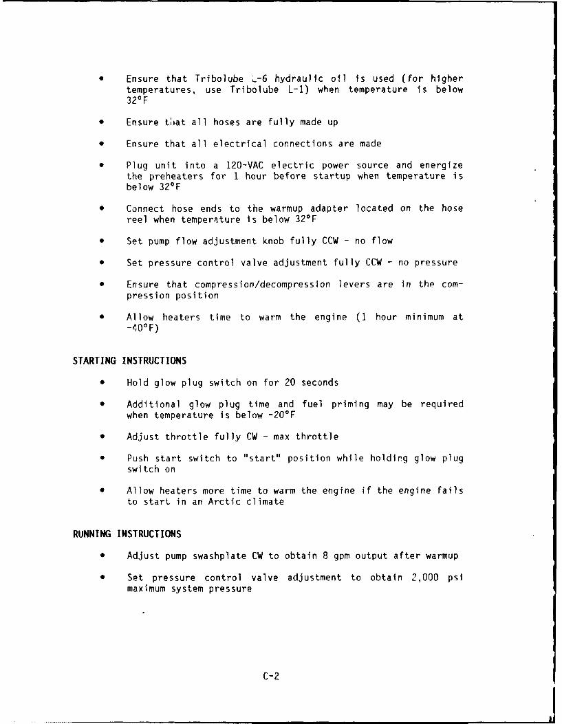
Ensure that Tribolube L-6 hydraulic oil is used (for highertemperatures, use Tribolube L-1) when temperature is below320F
* Ensure tat all hoses are fully made up
* Ensure that all electrical connections are made
* Plug unit into a 120-VAC electric power source and energizethe preheaters for 1 hour before startup when temperature isbelow 32*F
* Connect hose ends to the warmup adapter located on the hosereel when temperature is below 32'F
* Set pump flow adjustment knob fully CCW - no flow
* Set pressure control valve adjustment fully CCW - no pressure
* Ensure that compression/decompression levers are in the com-pression position
* Allow heaters time to warm the engine (1 hour minimum at-40-F)
STARTING INSTRUCTIONS
" Hold glow plug switch on for 20 seconds
* Additional glow plug time and fuel priming may be requiredwhen temperature is below -20*F
* Adjust throttle fully CW - max throttle
* Push start switch to "start" position while holding glow plugswitch on
* Allow heaters more time to warm the engine if the engine failsto start in an Arctic climate
RUNNING INSTRUCTIONS
* Adjust pump swashplate CW to obtain 8 gpm output after warmup
* Set pressure control valve adjustment to obtain 2,000 psimaximum system pressure
C-2

STOPPING INSTRUCTIONS
0 Set pump flow adj'ustment knob fully CCW - no flow
0 Set throttle to idle engine for 5 minutes
9 Push stor lever
* Push start switch to "off"
(Warning: Never use decompression levers -o stop engine)
C-3

DISTRIBUTION LIST
V92 CES / DEEE, Fairchild AFB, WAADMINSUPU / PWO, Bahrain, FPO New YorkAF / 1004 SSG/DE, Onizuka AFB, CAAF / 18 CESS/DEEEM, APO San Francisco; 438 ABG/DEE (Wilson), McGuire
AFB, NJ; 6550 ABG/DER, Patrick AFB, FL; CSR 4200 (K. Davidson),Patrick AFB, FL
AF HQ / ESD/AVDS, Hanscom AFB, MAAFB / 42d CES/Ready Officer, Loring AFB, MEAFB / 42d CES/DEMU (Dreschsel), Loring AFB, MEAF1 / HQ MAC/DEEE, Scott AFB, IL; HQ TAC/DEMM (Pollard), Langley AFB, VAAFESC / DEB, Tyndall AFB, FL; TIC Library, Tyndall AFB, FLAPPLIED TECHNOLOGY AND MANAGEMENT / C. Jones, Charleston, SCARCTEC, INC / Ches Instru Div, Tech Library, Glen Burnie, MDARMSTRONG, W. / Mystic, CTARMY / CEHSC-FU-N (Krajewski), Ft. Belvoir, VA; Ch of Engrs, DAEN-CWE-M,
Washington, DC; Ch of Engrs, DAEN-MPU, Washington, DC; Diving Det,Ft. Eustis, VA; FESA-EM (Karney), Ft. Belvoir, VA; (DAEN-ZCM),Washington, DC; Kwajalein Atoll, BMDSC-RKL-C, APO San Francisco;POJED-O, APO San Francisco
ARMY CECOM R&D TECH LIBRARY / ASNC-ELC-I-T, Ft Monmouth, NJARMY CERL / CECER-EME (Hayes), Champaign, IL; Library, Champaign, ILARMY CORPS OF ENGRS / A. Azares, Sacramento, CAARMY CRREL / CRREL-EG (Eaton), Hanover, NH; Iskandar, Hanover, NHARMY DEPOT / Letterkenny, SDSLE-EF, Chambersburg, PA; Letterkenny,
SDSLE-EN, Chambersburg, PAARMY ENGRG DIST / CENPS-ED-SD, Seattle, WA; Library, Portland, OR;
Library, Seattle, WA; Library, Philadelphia, PAARMY ENGRG DIV / ED-SY (Loyd), Huntsville, AL; HNDED-SY, Huntsville, ALARMY EWES / Library, Vicksburg, MS; WESCD (TW Richardson), Vicksburg, MS;
WESCD-P (Melby), Vicksburg, MS; WESCV-Z (Whalin), Vicksburg, MS;WESCW-D, Vicksburg, MS
ARMY HHC / 7th ATC, Grafenwohr, GE, APO New YorkARMY MMRC / DRXMR-SM (Lenoe), Watertown, MAARMY TRANS SCH / ATSP-CDM (Civilla), Fort Eustis, VAARVID GRANT & ASSOC / Olympia, WABATTELLE / D. Frink, Columbus, OHBAT rELLE NEW ENGLAND MARINE RSCH LAB / Library, Duxbury, MABECHTEL CIVIL, INC / K. Mark, San Francisco, CABLAYLOCK WILLIS & ASSOC / T Spencer, San Diego, CABRANSTROM, L / Ann Arbor, MIBULLOCK, TE / La Canada, CACALDWELL DIVING CO, INC / Toms River, NJCALIFORNIA / Nay & Ocean Dev (Armstrong), Sacramento, CACBC / Code 10, Davisville, RI; Code 155, Port Hueneme, CA; Code 430,
Gulfport, MS; Code 82, Port Hueneme, CA; PWO Code 400, Gulfport, MS;CBU / Code 401, OIC, Great Lakes, IL; Code 405, OIC, San Diego, CA; Code
411, OIC, Norfolk, VA; Code 417, OIC, Oak Harbor, WACHAO, JC / Houston, TXCHILDS ENGRG CORP / K.M. Childs, Jr., Medfield, MA

CITY OF AUSTIN / Gen Svcs Dept (Arnold), Austin, TXCITY OF MONTEREY / Const Mgr (Reichmuth), Monterey, CACITY OF RIVERSIDE / Bldg Svcs Dept, Riverside, CAGITY OF SACRAMENTO / Gen Svcs Dept, Sacramento, CACITY OF WINSTON-SALEM / RJ Rogers, PWD, Winston-Salem, NCCLARK, T. / Redding, CACLARKSON COLL OF TECH / CE Dept, Potsdam, NYCNO / DCNO, Logs, OP-424C, Washington, DCCOLORADO STATE UNIV / CE Dept (Criswell), Ft. Collins, COCOM GEN FMF / LANT, SCE, Norfolk, VACOMCBLANT / Code S3T, Norfolk, VACOMDT COGUARD / G-ECV, Washington, DCCOMFLEACT / PWO, FPO Seattle; SCE, FPO SeattleCOMNAVACT / G.T. Clifford, London, UK, FPO New York; PWO, London, UK,
FPO New YorkCOMNAVAIR / Lant, Nuc Wpns Sec Offr, Norfolk, VACOMNAVAIRSYSCOM / AIR-714, Washington, DCCOMNAVLOGPAC / Code 4318, Pearl Harbor, HICOMNAVRESFOR / Code 08, New Orleans, LA; Code 823, New Orleans, LACOMOCEANSYS / PAC, SCE, Pearl Harbor, HICOMSUBPAC / SCE, Pearl Harbor, HICONSOER TOWNSEND & ASSOC / Schramm, Chicago, ILCONSTRUCTION TECH LABS, INC / G. Corley, Skokie, ILCORNELL UNIV / Civil & Environ Engrg, Ithaca, NY; Library, Ithaca, NYCUE INC / M. Kocak, Mars, PACURTIS, C. / Ventura, CADAVY DRAVO / Wright, Pittsburg, PADE PALMA, J R. / Picayune, MSDFSC / F, Alexandria, VADOBROWOLSKI, JA / Altadena, CADODDS / PAC, FAC, FPO SeattleDTRCEN / Code 172, Bethesda, MD; Code 284, Annapolis, MD; Code 4111,
Bethesda, MD; Code 4120, Annapolis, MD; Code 42, Bethesda, MDEASTPORT INTL, INC / JH Osborn, Mgr, Ventura, CAEDWARD K NODA & ASSOC / Honolulu, HIENERCOMP / Amistadi, Brunswick, MEEWI ENGINEERING ASSOCIATES / Jack Cox, Middleton, WIFCTC / LANT, Code 182, Virginia Beach, VA; LANT, PWO, Virginia Beach, VAFLORIDA ATLANTIC UNIV / Ocean Engrg Dept (Hart), Boca Raton, FL; Ocean
Engrg Dept (Martin), Boca Raton, FL; Ocean Engrg Dept (McAllister),Boca Raton, FL
FLORIDA INST OF TECH / CE Dept (Kalajian), Melbourne, FLFOWLER, J.W. / Virginia Beach, VAGDM & ASSOC, INC. / Fairbanks, AKGENERAL DYNAMICS / D-443 (Leone), Groton, CTGEOTECHNICAL ENGRS, INC / Murdock, Winchester, MAGOLDER ASSOC / Brumund, Atlanta, GAGSA / Code Engrg Branch, PQB, Washington, DCHALEY & ALDRICH, INC. / Chet Seydemir, Cambridge, MAHAN-PADRON ASSOCIATES / Dennis Padron, New York, NYHANDLEY, DM / Gulf Breeze, FLHARDY, S.P. / San Ramon, CAHAYNES & ASSOC / H. Haynes, PE, Oakland, CA
HAYNES, B / Lynden, WAHENRICO CO. GEN SVCS / JW Warren, Richmond, VAHERONEMUS, W.E. / Amherst, MAHOPE ARCHTS & ENGRS / San Diego, CAHQ AFLC / DEMM, W-ight-Patter-or- AFB, OHINST OF MARINE SCIENCES / Dir, Morehead City, NC; Library, Port Aransas, TXINTL MARITIME, INC / D. Walsh, San Pedro, CAKLIEGER, PAUL / CE, Northbrook, ILKTA-TATOR, INC / Pittsburg, PALAWRENCE LIVERMORE NATL LAB / Plant Engrg Lib (L-654), Livermore, CALAYTON & SELL, INC, P.S. / Redmond, WALEHIGH UNIV / Marine Geotech Lab, Bethleham, PALEO A DALY CO / Honolulu, HILEVINE-FRICKE / Newport Beach, CALIN OFFSHORE ENGRG / P. Chow, San Francisco, CALONG BEACH PORT / Engrg Dir (Allen), Long Beach, CA; Engrg Dir (Lizzi),
Long Beach, CALOS ANGELES COUNTY / PW Dept (J. Vicelja), Harbor City, CAMAG / 16, CO, MCAS, Tustin, CAMAINE MARITIME ACADEMY / Library, Castine, MEMARATHON OIL CO / Gamble, Houston, TXMARBKS / Sec Offr, FPO San FranciscoMARCORBASE / Base Maint Dept, Camp Lejeune, NC; Code 4.01, Camp
Pendleton, CA; Code 405, Camp Lejeune, NC; Code 406, Camp Lejeune,NC; Facilities Coordinator, Camp Pendleton, CA; Maint Offr, CampPendleton, CA; PAC, PWO, FPO Seattle
MARCORDIST / 12, Code 4, San Francisco, CAMARCORPS / FIRST FSSG, Engr Supp Offr, Camp Pendleton, CAMARINE CONCRETE STRUCTURES, INC / W.A. Ingraham, Metairie, LAMARITECH ENGRG / Donoghue, Austin, TXMARITIME ADMIN / MMA, Library, Kings Point, NYMC CLELLAND ENGRS, INC / Library, Houston, TXMCA ENGINEERS / Shane, Camarillo, CAMCAS / Code IJE.50 (Isaacs), Santa Ana, CA; Code 6EDD, FPO Seattle; Code
LCU, Cherry Point, NC; Code LE, Cherry Point, NC; El Toro, CodelJD, Santa Ana, CA; PWO, Kaneohe Bay, HI
MCLB / Code 506, Albany, GAMCRDAC / AROICC, Quantico, VAMERMEL, TW / Washington, DCMICHIGAN TECH UNIV / CO Dept (Haas), Houghton, MIMOBIL R&D Corp / Offshore Engrg Library, Dallas, TXMOFFATT & NICHOL ENGRS / R. Palmer, Long Beach, CAMT DAVISSON / CE, Savoy, ILNAF / Dir, Engrg Div, PWD, FPO Seattle; PWO, FPO San Francisco; PWO,
FPO SeattleNALF / OIC, San Diego, CANAS / Chase Fld, PWO, Beeville, TX; Code 072E, Willow Grove, PA; Code
163, Keflavik, Iceland, FPO New York; Code 18300, Kingsville, TX;Code 18300, Lemoore, CA; Code 1833, Corpus Christi, TX; Code 18700,Brunswick, ME; Code 421, San Diego, CA; Code 6234 (C. Arnold),Point Mugu, CA; Code 70, Marietta, GA; Code 725, Marietta, GA; Code8, Patuxent River, MD; Code 83, Patuxent River, MD; Dir, Engrg Div,PWD, Keflavik, Iceland, FPO New York; Fac Mgmt Offc, Alameda, CA;
Lead CPO, PWD, Self Help Div, Beeville, TX; Memphis, PWO,Millington, TN; Miramar, PWO, San Diego, CA; Miramar, PWO, Code183, San Diego, CA; Miramar, PWO, Code 187, San Diego, CA; NI, Code183, San Diego, CA; P&E Supr, FPO Seattle; PW Engrg, PatuxentRiver, MD; PWD Maint Div, New Orleans, LA; PWO Code 6200, PointMugu, CA; PWO, Cecil Field, FL; PWO, Corpus Christi, TX; FWO, KeyWest, FL; PWO, Meridian, MS; PWO, Moffett Field, CA; PWO, WillowGrove, PA; PWO, Sigonella, Italy, FPO New York; SCE, Barbers Point,HI; SCE, FPO San Francisco; SCE, Norfolk, VA; Whidbey Is, PW-2, OakHarbor, WA; Whidbey Is, PWE, Oak Harbor, WA; Memphis, Code 18200,Millington, TN; Memphis, Dir, Engrg Div, Millington, TN
NAS ADAK / Code 114, FPO Seattle,NAS NPWC / Code 102 (J. Aresto), San Diego, CANATL ACADEMY OF SCIENCES / BRB, (Smeallie), Washington, DCNAVAIRDEVCEN / Code 832, Warminster, PANAVAVIONICCEN / Code D-701, Indianapolis, INNAVAVNDEPOT / Code 61000, Cherry Point, NC; Code 61000, Pensacola, FL;
Code 640, Pensacola, FL; SCE, Norfolk, VANAVCAMS / MED, SCE, Naples, Italy, FPO New York; PWO, Norfolk, VA; SCE,
Wahiawa, HI; WESTPAC, SCE, FPO San FranciscoNAVCOASTSYSCEN / Code 423, Panama City, FL; Code 715 (J. Mittleman),
Panama City, FL; PWO (Code 740), Panama City, FLNAVCOMMSTA / PWO, FPO San Francisco; PWO, Thurso, UK, FPO New YorkNAVCONSTRACEN / Code B-l, Port Hueneme, CA; Code D2A, Port Hueneme, CA;
Code S24, Gulfport, MSNAVEODTECHCEN / Tech Library, Indian Head, MDNAVFAC / Centerville Bch, PWO, Ferndale, CA; N62, Argentina, NF, FPO New
York; PWO, Oak Harbor, WANAVFACENGCOM / Code 04AID, Alexandria, VA; Code 04A3, Alexandria, VA;
Code 04A3C, Alexandria, VA; Code 04B3, Alexandria, VA; Code 051A,Alexandria, VA; Code 1002B, Alexandria, VA; Code 163, Alexandria,VA; Code DS02, Alexandria, VA
NAVFACENGCOM / CHESDIV Code 112.1, Washington, DC; Code 407, Washington, DCNAVFACENGCOM CONTRACTS / AROICC, Coleville, CA; AROICC, Quantico, VA;
DROICC, FPO Seattle; DROICC, Lemoore, CA; North Bay, Code 1042.AA,Vallejo, CA; ROICC (Code 495), Portsmouth, VA; ROICC, Crane, IN;ROICC, Jacksonville, FL; ROICC, Philadelphia, PA; ROICC, PointMugu, CA; ROICC, Santa Ana, CA; ROICC, Twentynine Palms, CA
NAVFACENGCOM LANTDIV / Code 403, Norfolk, VANAVFACENGCOM NORTHDIV / CO, Philadelphia, PANAVFACENGCOM NORTHDIV / Code 111, Philadelphia, PA; Code 202.2,
Philadelphia, PANAVFACENGCOM PACDIV / Code 102, Pearl Harbor, HI; Code 2011, Pearl
Harbor, HINAVFACENGCOM SOUTHDIV / Code 04A3, Charleston, SC; Code 0525,
Charleston, SC; Code 1021F, Charleston, SC; Code 102B, Charleston,SC; Code 102H, Charleston, SC; Code 4023 (RDL), Charleston, SC;Code 4023, Charleston, SC; Code 405, Charleston, SC
NAVFACENGCOM WESTDIV / Code 09B, San Bruno, CA; Code 09P/20, San Bruno,CA; Code 102, San Bruno, CA; Code 403.2 (Kelly), San Bruno, CA;Code 406.2 (Smith), San Bruno, CA; Code 407, San Bruno, CA; PAC NWBr Offc, Code C/42, Silverdale, WA; ROICC, Silverdale, WA

NAVHOSP / CO, Millington, TN; PWO, FPO Seattle; SCE, FPO San Francisco;SCE, FPO Seattle
NAVMAG / SCE, FPO San FranciscoNAVOCEANCOMCEN / Code EES, FPO San FranciscoNAVOCEANO / Code 6200 (M Paige), NSTL, MS; Library, NSTL, MSNAVOCEANSYSCEN / Code 9642B, San Diego, CANAVPETOFF / Sec Offr (Code 20), Alexandria, VANAVPGSCOL / Code 68WY (Wyland), Monterey, CANAVPHIBASE / PWO, Norfolk, VA; SCE, San Diego, CANAVPWC / Taylor, Pensacola, FLNAVSCSCOL / PWO, Athens, GANAVSEA DET / NISMF Pearl Harbor, Director, Waipahu, HINAVSEASYSCOM / Code 05M3, Washington, DCNAVSECGRU / Code G43, Washington, DCNAVSECGRUACT / CO, FPO Miami; Code 31 PWO, FPO Miami; PWO (Code 40),
Edzell, Scotland, FPO New York; PWO, FPO SeattleNAVSECSTA / Code 60, Washington, DCNAVSHIPREPFAC / SCE, FPO San Francisco; SCE, FPO SeattleNAVSHIPYD / Carr Inlet Acoustic Range, Bremerton, WA; CO, Philadelphia,
PA; Code 134, Pearl Harbor, HI; Code 244.13, Long Beach, CA; Code308.3, Pearl Harbor, HI; Code 382.3, Pearl Harbor, HI; Code 420,Long Beach, CA; Code 441, Portsmouth, NH; Code 443, Bremerton, WA;Code 450.4, Charleston, SC; Code 903, Long Beach, CA; Mare Is, Code106.4, Vallejo, CA; Mare Is, Code 202.13, Vallejo, CA; Mare Is,Code 280, Vallejo, CA; Mare Is, Code 401, Vallejo, CA; Mare Is,Code 421, Vallejo, CA; Mare Is, Code 440, Vallejo, CA; Mare Is,Code 457, Vallejo, CA; Mare Is, PWO, Vallejo, CA; Norfolk, Code380, Portsmouth, VA; Norfolk, Code 440, Portsmouth, VA; TechLibrary, Portsmouth, NH
NAVSTA / CO, Brooklyn, NY; CO, Long Beach, CA; Code 423, Norfolk, VA;Design Sec, Brooklyn, NY; Dir, Engr Div, PWD, Guantanamo Bay, Cuba,FPO New York; Engr Div, PWD, FPO Miami; Engrg Dir, PWD, Rota,Spain, FPO New York; PWO, Mayport, FL; PWO, Guantanamo Bay, Cuba,FPO New York; PWO, Rota, Spain, FPO New York; Sec Offr, FPO SanFrancisco; Util Engrg Offr, Rota, Spain, FPO New York
NAVSUPCEN / Code 700A.1, Norfolk, VANAVSUPPACT / PWO, Holy Loch, UK, FPO New York; PWO, Naples, Italy, FPO
New YorkNAVSUPPFAC / Contract Assistant, FPO San FranciscoNAVSUPPO / Sec Offr, La Maddalena, Italy, FPO New YorkNAVSUPSYSCOM / Code 0622, Washington, DCNAVSWC / Code W41Cl, Dahlgren, VA; Code W42 (GS Haga), Dahlgren, VA;
DET, White Oak Lab, PWO, Silver Spring, MD; PWO, Dahlgren, VANAVTECHTRACEN / SCE, Pensacola, FLNAVTRASTA / PWO, Orlando, FLNAVWPNCEN / Code 2634, China Lake, CA; Code 2637, China Lake, CA; PWO
(Code 266), China Lake, CANAVWPNSTA / Code 092, Concord, CA; Code 093, Yorktown, VA; PWO,
Yorktown, VANAVWPNSTA EARLE / Code 092, Colts Neck, NJNCR / 20, CO, Gulfport, MS; 20, Code R70, Gulfport, MSNE OHIO REG SEWER DIST / Bldg Maint (Scherma), Cuyahoga Heights, OHNEESA / Code 111C (Hickenbottom), Port Hueneme, CA; Code 111E3, Port
Hueneme, CA

NETPMSA / Tech Library, Pensacola, FLNMCB / 3, Ops Offr, FPO San Francisco; 40, CO, FPO San Francisco; 74,
CO, FPO MiamiNOAA / Library, Rockville, MDNORDA / Code 1121SP, NSTL, MONORTHDIV CONTRACTS OFFICE / ROICC, Colts Neck, NJ; ROICC, Portsmouth, NHNPWC / Code 310, Pensacola, FLNRL / Code 2511, Washington, DC; Code 2530.1, Washington, DC; Code 6123,
Washington, DC; Code 6127, Washington, DCNSC / Code 43, Oakland, CA; Code 54.1, Norfolk, VA; Code 700, Norfolk,
VA; Code 700P/M (Fuel Dir), Richmond, CA; Code 703, Pearl Harbor,HI; SCE, Charleston, SC; SCE, Norfolk, VA; SCE, Pearl Harbor, HI
NUHN & ASSOC / A.C. Nuhn, Wayzata, NMNUSC DET / Code 2143 (Varley), New London, CT; Code 3322 (Brown), New
London, CT; Code 44 (Munn), New London, CT; Code TA131, New London,CT; Library, Newport, RI
NWSTAT / ROICC, Colts Neck, NJOCNR / Code 1121 (EA Silva), Arlington, VA; Code 1234, Arlington, VAOFFICE OF SEC OF DEFENSE / OASD (P&L)E, Washington, DCOICC / Engr and Const Dept, APO New YorkOREGON STATE UNIV / CE Dept (Hicks), Corvallis, OR; CE Dept (Yim),
Corvallis, OROREGON STATE UNIV / Oceanography Scol, Corvallis, ORPACIFIC MARINE TECH / M. Wagner, Duvall, WAPAULI, DC / Silver Spring, MDPAYE-KOSANOWSKY, S / Pond Eddy, NYPENNSYLVANIA STATE UNIV / Rsch Lab, State College, PAPHILADELPHIA ELEC CO / E. D. Freas, West Chester, PAPIKE, L / San Antonio, TXPILE BUCK, INC / Smoot, Jupiter, FLPMTC / Code 5041, Point Mugu, CAPWC / ACE Office, Norfolk, VA; CO, Oakland, CA; Code 101, Great Lakes,
IL; Code 1011, Pearl Harbor, HI; Code 110, Oakland, CA; Code 123C,San Diego, CA; Code 400, Oakland, CA; Code 400A.3, FPO SanFrancisco; Code 412, San Diego, CA; Code 420, Oakland, CA; Code 421(Kaya), Pearl Harbor, HI; Code 421 (Quin), San Diego, CA; Code 421(Reynolds), San Diego, CA; Code 421, Norfolk, VA; Code 422, SanDiego, CA; Code 423, San Diego, CA; Code 430 (Kyi), Pearl Harbor,HI; Code 50, Pensacola, FL; Code 500, San Diego, CA; Code 505A,Oakland, CA; Code 590, San Diego, CA; Code 600, Great Lakes, IL;Code 612, Pearl Harbor, HI; Code 612, Pearl Harbor, HI; Code 615,FPO San Francisco; Code 700, Great Lakes, IL; Code 700, San Diego,CA; Waid, San Diego, CA
SAN DIEGO STATE UNIV / CE Dept (Noorany), San Diego, CASEATECH CORP / Peroni, Miami, FLSEATTLE PORT / Dave Van Vleet, Seattle, WASEATTLE UNIV / CE Dept (Schwaegler), Seattle, WASIMPSON, GUMPERTZ & HEGER, INC / Hill, Arlington, MASMELSER, D / Sevierville, TNSOUTHWEST RESEARCH INSTITUTE / Thacker, San Antonio, TXSOUTHWEST RSCH INST / M. Polcyn, San Antonio, TXSPCC / Code 082, Mechanicsburg, PA; PWO, Mechanicsburg, PASTATE UNIV OF NEW YORK / CE Dept, Buffalo, NY

SUBASE / Bangor, PWO (Code 8323), Bremerton, WASUPSHIP / Tech Library, Newport News, VATAMPA PORT AUTHORITY / Engrg Dept (Schrader), Tampa, FLTECHNOLOGY UTILIZATION / K Willinger, Washington, DCTEXAS A&M UNIV / CE Dept (Herbich), College Station, TX; CE Dept (Machemehl),
College Station, TX; Ocean Engr Proj, College Station, TXTEXTRON, INC / Rsch Cen Library, Buffalo, NYTHE KLING-LINDQUIST, INC / Radwan, Philadelphia, PATREMCO, INC / M. Raymond, Cleveland, OHTRW INC / Rodgers, Redondo Beach, CAUCT TWO / CO, Port Hueneme, CAUCT ONE / CO, Norfolk, VAUNIV OF ALABAMA / Dir Fac Mgmt (Baker), Birmingham, ALUNIV OF CALIFORNIA / CE Dept (Fourney), Los Angeles, CA; CE Dept
(Gerwick), Berkeley, CA; CE Dept (Polivka), Berkeley, CA; CE Dept(Taylor), Davis, CA; Marine Rsrs Inst (Spiess), LaJolla, CA
UNIV OF DELAWARE / Engrg Col (Dexter), Lewes, DEUNIV OF HAWAII / Manoa, Library, Honolulu, HIUNIV OF HAWAII / Ocean Engrg Dept (Ertekin), Honolulu, HIUNIV OF ILLINOIS / Arch Scol (Kim), Champaign, IL; Metz Ref Rm, Urbana, ILUNIV OF RHODE ISLAND / CE Dept, Kingston, RI; Dr. Veyera, Kingston, RIUNIV OF TEXAS / CE Dept (Thompson), Austin, TX; Construction Industry
Inst, Austin, TX; ECJ 4.8 (Breen), Austin, TX; ECJ 5.402 (Tucker),Austin, TX; MScol, Marine Biomed Inst, Talveston, TX
UNIV OF WASHINGTON / Applied Phys Lab (Sandwith), Seattle, WA; AppliedPhy Lab Library, Seattle, WA; CE Dept (Mattock), Seattle, WA
UNIV OF WISCONSIN / Great Lakes Studies Cen, Milwaukee, WIUS DEPT OF INTERIOR / BLM, Engrg Div (730), Washington, DCUSCINCPAC / Code J44, Camp HM 1:-4,h, HIUSCOASTGUARDACADEMY / Superintend.it, New London, CTUSDA / For Svc, Reg Bridge Engr, Aloha, OR; Forest Prod Lab (Johnson),
Madison, WIUSNA / Ocean Engrg Dept, Annapolis, MD; PWO, Annapolis, MDUSNA / Sys Engrg, Annapolis, MDVALLEY FORGE CORPORATE CENTER / Franklin Research Center, Norristown, PAVAN ALLEN, B / Kingston, NYVENTURA COUNTY / Deputy PW Dir, Ventura, CA; PWA (Brownie), Ventura, CAVIATEUR DE CHAMPLAIN / Inst of Maritime Engrg, Matane, QuebecVULCAN IRON WORKS, INC / DC Warrington, Cleveland, TNWESCR-P / Hales, Vicksburg, MSWINSTON CHEE / Gretna, LAWISWELL, INC. / Wiswell, Southport, CTWOODWARD-CLYDE CONSULTANTS / R. Cross, Oakland, CA; West Reg, Library,
Oakland, CA


![Portable Hydraulic Dental Chairq9bgh9q08416907ck9fxol3z-wpengine.netdna-ssl.com/wp...• Portable hydraulic dental chair [PN ADC-02] • Operation/maintenance manual & parts list [PN](https://static.fdocuments.in/doc/165x107/60bc4f089748f40cf868d8ea/portable-hydraulic-dental-chairq9bgh9q08416907ck9fxol3z-a-portable-hydraulic.jpg)