Portable Hardness Tester - Polygon Instru · Portable Hardness Tester User's Manual. ... (Brinell,...
21
Portable Hardness Tester User ' s Manual
Transcript of Portable Hardness Tester - Polygon Instru · Portable Hardness Tester User's Manual. ... (Brinell,...
Portable Hardness Tester
User's Manual
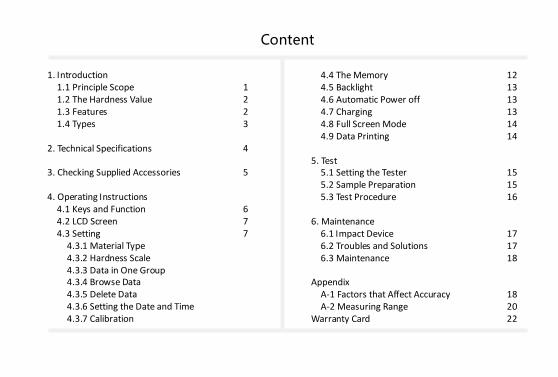
Content
1. Introduction 1.1 Principle Scope 1 1.2 The Hardness Value 2 1.3 Features 2 1.4 Types 3 2. Technical Specifications 4 3. Checking Supplied Accessories 5 4. Operating Instructions 4.1 Keys and Function 6 4.2 LCD Screen 7 4.3 Setting 7 4.3.1 Material Type 4.3.2 Hardness Scale 4.3.3 Data in One Group 4.3.4 Browse Data 4.3.5 Delete Data 4.3.6 Setting the Date and Time 4.3.7 Calibration
4.4 The Memory 12 4.5 Backlight 13 4.6 Automatic Power off 13 4.7 Charging 13 4.8 Full Screen Mode 14 4.9 Data Printing 14 5. Test 5.1 Setting the Tester 15 5.2 Sample Preparation 15 5.3 Test Procedure 16 6. Maintenance 6.1 Impact Device 17 6.2 Troubles and Solutions 17 6.3 Maintenance 18 Appendix A-1 Factors that Affect Accuracy 18 A-2 Measuring Range 20 Warranty Card 22
1
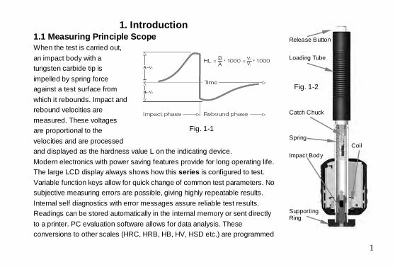
1. Introduction 1.1 Measuring Principle Scope When the test is carried out, an impact body with a tungsten carbide tip is impelled by spring force against a test surface from which it rebounds. Impact and rebound velocities are measured. These voltages are proportional to the velocities and are processed and displayed as the hardness value L on the indicating device. Modern electronics with power saving features provide for long operating life. The large LCD display always shows how this series is configured to test. Variable function keys allow for quick change of common test parameters. No subjective measuring errors are possible, giving highly repeatable results. Internal self diagnostics with error messages assure reliable test results. Readings can be stored automatically in the internal memory or sent directly to a printer. PC evaluation software allows for data analysis. These conversions to other scales (HRC, HRB, HB, HV, HSD etc.) are programmed
Fig. 1-1
Release Button
Loading Tube
Spring
Catch Chuck
Coil
Fig. 1-2
Supporting Ring
Impact Body
2
into the electronics and can be shown directly on the display as the test result. 1.2 The Hardness Value With reference to a particular material group (e.g. steel, aluminum etc.), the L-value represents a direct hardness measurement and is used as such. Comparison curves with standard static hardness values have been established (Brinell, Vickers, Rockwell C, B, Shore D) for the most prevalent materials, enabling the L-value to be converted into the relevant values for these procedures. The hardness values can be directly displayed in the hardness scales HLD, HRC, HRB, HB, HV, HSD. 1.3 Features The most advanced integrated tester (Impact Device D integrated): no cables Integrated impact direction sensor Highly accuracy (±6HL) in any impact direction (360°) – automatically Integrated display of results for all common hardness scales Large, high contrast LCD for optimum viewing in all conditions Easy calibration Full USB communication with PC, software included free of charge Internal storage of data with day and time Rechargeable Li-ion battery, charges through USB port Intelligent sleep mode Wireless mini printer
3
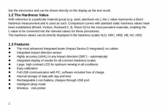
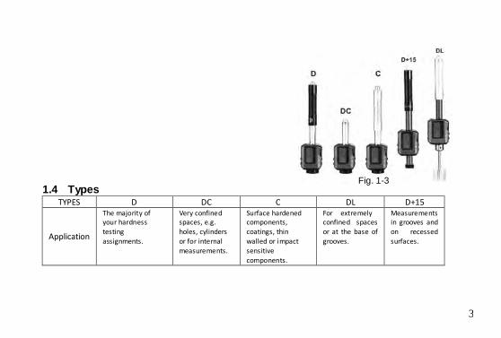
1.4 Types TYPES D DC C DL D+15
Application
The majority of your hardness testing assignments.
Very confined spaces, e.g. holes, cylinders or for internal measurements.
Surface hardened components, coatings, thin walled or impact sensitive components.
For extremely confined spaces or at the base of grooves.
Measurements in grooves and on recessed surfaces.
Fig. 1-3
4
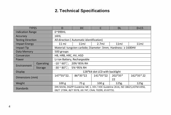
2. Technical Specifications
TYPES D DC C DL D+15 Indication Range 0~999HL Accuracy ±4HL Testing Direction All direction ( Automatic identification) Impact Energy 11 mJ 11mJ 2.7mJ 11mJ 11mJ Impact Tip Material: tungsten carbide; Diameter: 3mm; Hardness: ≥ 1600HV Data Memory 500 groups Conversion HB, HRB, HRC, HV, HSD Power Li-Ion Battery, Rechargeable
Environment Operating -10 ~ 60℃; 20%~85% RH Storage -30 ~ 80℃; 5%~95% RH
Display 128*64 dot LCD with backlight
Dimensions (mm) 147*35*22. 86*35*22 141*35*22 202*35* 22
162*35* 22
Weight 100 g 75 g 100 g 125g. 125g
Standards DIN 50156, DGZfP Guideline MC 1, VDI / VDE Guideline 2616, ISO 18625,ASTM A956, GB/T 17394, JB/T 9378, JJG 747, CNAL T0299, JIS B7731.
5
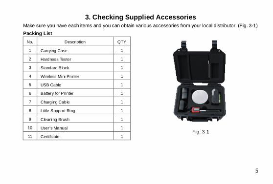
3. Checking Supplied Accessories Make sure you have each items and you can obtain various accessories from your local distributor. (Fig. 3-1) Packing List
No. Description QTY.
1 Carrying Case 1
2 Hardness Tester 1
3 Standard Block 1
4 Wireless Mini Printer 1
5 USB Cable 1
6 Battery for Printer 1
7 Charging Cable 1
8 Little Support Ring 1
9 Cleaning Brush 1
10 User’s Manual 1
11 Certificate 1
Fig. 3-1
6
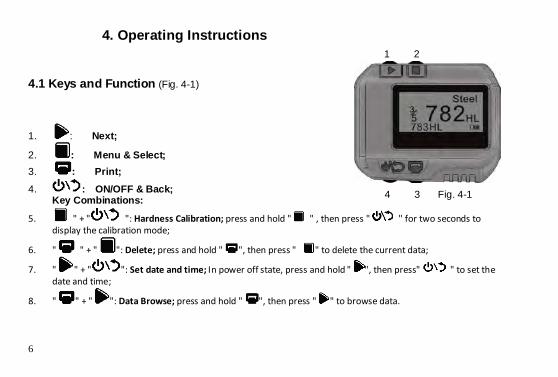
4. Operating Instructions 4.1 Keys and Function (Fig. 4-1)
1. : Next;
2. : Menu & Select; 3. : Print; 4. : ON/OFF & Back;
Key Combinations:
5. " + " ": Hardness Calibration; press and hold " " , then press " " for two seconds to display the calibration mode;
6. " " + " ": Delete; press and hold " ", then press " " to delete the current data;
7. " " + " ": Set date and time; In power off state, press and hold " ", then press" " to set the date and time;
8. " " + " ": Data Browse; press and hold " ", then press " " to browse data.
1 2
4 3 Fig. 4-1
7
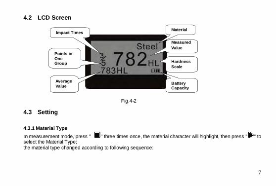
4.2 LCD Screen
4.3 Setting 4.3.1 Material Type In measurement mode, press " " three times once, the material character will highlight, then press " " to select the Material Type; the material type changed according to following sequence:
Average Value
Measured Value
Impact Times
Points in One Group
Battery Capacity
Fig.4-2
Hardness Scale
Material
8
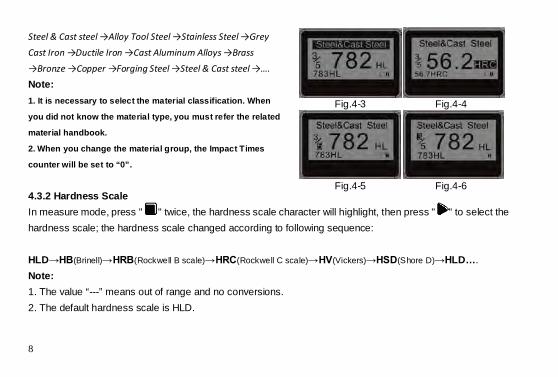
Fig.4-3 Fig.4-4
Fig.4-5 Fig.4-6
Steel & Cast steel →Alloy Tool Steel →Stainless Steel →Grey Cast Iron →Ductile Iron →Cast Aluminum Alloys →Brass →Bronze →Copper →Forging Steel →Steel & Cast steel →…. Note: 1. It is necessary to select the material classification. When
you did not know the material type, you must refer the related
material handbook.
2. When you change the material group, the Impact Times
counter will be set to “0”.
4.3.2 Hardness Scale In measure mode, press " " twice, the hardness scale character will highlight, then press " " to select the hardness scale; the hardness scale changed according to following sequence: HLD→HB(Brinell)→HRB(Rockwell B scale)→HRC(Rockwell C scale)→HV(Vickers)→HSD(Shore D)→HLD…. Note: 1. The value “---” means out of range and no conversions. 2. The default hardness scale is HLD.
9
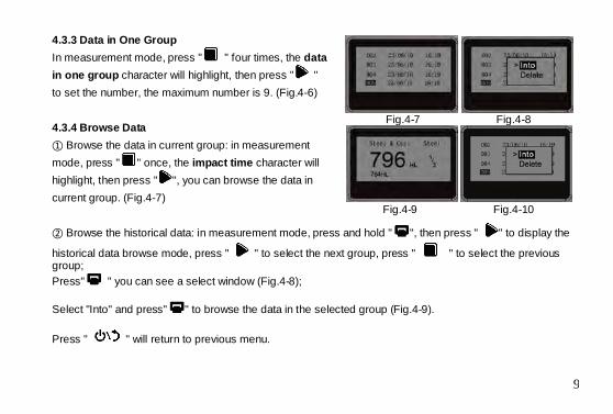
Fig.4-7 Fig.4-8
Fig.4-9 Fig.4-10
4.3.3 Data in One Group In measurement mode, press " " four times, the data in one group character will highlight, then press " " to set the number, the maximum number is 9. (Fig.4-6) 4.3.4 Browse Data ① Browse the data in current group: in measurement mode, press " " once, the impact time character will highlight, then press " ", you can browse the data in current group. (Fig.4-7) ② Browse the historical data: in measurement mode, press and hold " ", then press " " to display the
historical data browse mode, press " " to select the next group, press " " to select the previous group; Press" " you can see a select window (Fig.4-8); Select "Into" and press" " to browse the data in the selected group (Fig.4-9). Press " " will return to previous menu.
10
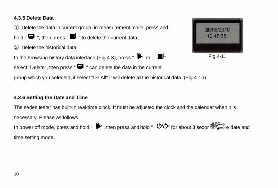
Fig.4-11
4.3.5 Delete Data
① Delete the data in current group: in measurement mode, press and
hold " ", then press " " to delete the current data.
② Delete the historical data:
In the browsing history data interface (Fig.4-8), press " " or " "
select "Delete", then press " " can delete the data in the current
group which you selected, if select "DelAll" it will delete all the historical data. (Fig.4-10)
4.3.6 Setting the Date and Time
The series tester has built-in real-time clock, It must be adjusted the clock and the calendar when it is
necessary. Please as follows:
In power off mode, press and hold " ", then press and hold " " for about 3 seconds to the date and
time setting mode.
11
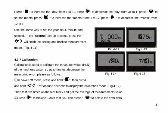
Fig.4-12 Fig.4-13
Fig.4-14 Fig.4-15
Press " " to increase the "day" from 1 to 31, press " " to decrease the "day" from 31 to 1; press " " to
set the month, press " " to increase the "month" from 1 to 12, press " " to decrease the "month" from
12 to 1.
Use the same way to set the year, hour, minute and
second. In the "second" set-up process, press the "
" will finish the setting and back to measurement
mode. (Fig. 4-11)
4.3.7 Calibration Calibration is used to calibrate the measured value (HLD) of the hardness tester, so as to farthest decrease the measuring error, please as follows:
①In power off mode, press and hold " ", then press
and hold " " for about 3 seconds to display the calibration mode (Fig.4-12).
Then test five times on the test block and get the average of measurements value.
②Press " " to browse 5 data test, you can press " " to delete the error data.
12
③Press " " to display the mode like (Fig. 4-13), the "hundred" bit will be highlighted, input the HLD value
that marked on test block.
④Press " " to increase from 0 to 9, to set the "hundred" bit.
⑤Press the " " the "ten" bit will be highlighted, Press " " to increase from 0 to 9, to set the "ten" bit
(Fig.4-14).
⑥Press the " " the "last" bit will be highlighted, Press " " to increase from 0 to 9, to set the "last"
bit(Fig.4-15).
⑦Press " " to return to the measurement mode, the calibration is finish.
Note: 1. You should calibrate it on the test block before your first use the hardness tester. 2. The impact direction must be down straight.
4.4 The Memory The data (such as hardness value, scale, sample material and impact direction, time, date etc.) will be saved in memory automatically after one individual impact. The tester can store 500 data, when test times are more than 500, the last data will be stored in the 1th position and the first data will be erased, simultaneously the position of other data will be moved into lower position.
13
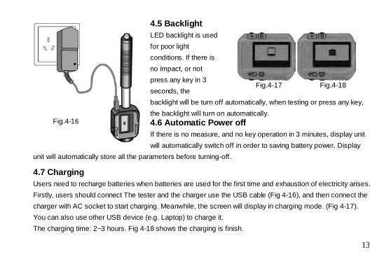
Fig.4-17 Fig.4-18
4.5 Backlight LED backlight is used for poor light conditions. If there is no impact, or not press any key in 3 seconds, the backlight will be turn off automatically, when testing or press any key, the backlight will turn on automatically. 4.6 Automatic Power off If there is no measure, and no key operation in 3 minutes, display unit will automatically switch off in order to saving battery power. Display
unit will automatically store all the parameters before turning-off.
4.7 Charging Users need to recharge batteries when batteries are used for the first time and exhaustion of electricity arises. Firstly, users should connect The tester and the charger use the USB cable (Fig 4-16), and then connect the charger with AC socket to start charging. Meanwhile, the screen will display in charging mode. (Fig 4-17). You can also use other USB device (e.g. Laptop) to charge it. The charging time: 2~3 hours. Fig 4-18 shows the charging is finish.
Fig.4-16
14
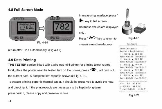
4.8 Full Screen Mode In measuring interface, press "
" key to full screen.
Hardness values are displayed
only .
Press " " key to return to
measurement interface or
return after 2 s automatically. (Fig 4-19)
4.9 Data Printing THE TESTER can be linked with a wireless mini printer for printing a test report. First, place the printer near the tester, turn on the printer, press " " , will print out
the current data. A complete test report is shown at Fig. 4-21.
Because printing paper is thermal paper, it should be preserved to avoid the heat
and direct light. If the print records are necessary to be kept in long-term
preservation, please copy and preserve in time.
Fig 4-19
Fig.4-21
Fig.4-20
15
5. Test 5.1 Setting the Tester Press " " to turn on, and check if it’s need to charge. Inspect if every setting of is correctly, particularly the
material type and scale. The setting inconsistent with the actual condition may cause a great error. 5.2 Sample Preparation Preparation of the sample and the surface of test should be coincident with the following basic requirements: 1) During the process of sample surface preparation, users should avoid the impacts of cold processing and
thermal processing. 2) The sample surface is plane for better, the test surface should be with a metallic sheen, and not involve
oxide layer or other stains. 3) Roughness of the test surface see A-1 1). 4) Sample must be of sufficient mass and rigidity. If it’s lack of quality and rigidity, it may cause displacement
or shaking in the process of testing impact, which can lead to large errors. See A-1 3)Coupling method: Testing sample’s back should be prepared to make a plane as a supporting surface with a smooth formation. Filling with a little coupling substance (Industry Vaseline can be used), users can now press to the surface of the supporting object (The weight of supporting object should be more than 5 kg, and it can be replaced by test block) to stick into integration.
16
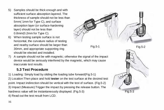
5) Samples should be thick enough and with sufficient surface absorption layered. The thickness of sample should not be less than 5mm( 1mm for Type C), and surface absorption layer (or surface-hardening layer) should not be less than 0.8mm(0.2mm for Type C).
6) When testing sample surface is not horizontal, the curvature radius of testing and nearby surface should be larger than 30mm, and appropriate supporting ring should be elected and installed.
7) A sample should not be with magnetic; otherwise the signal of the impact device would be seriously interfered by the magnetic, which may cause inaccurate test results.
5.3 Test Procedure 1) Loading: Simply load by sliding the loading tube forward(Fig.5-1) 2) Location:Then place and hold tester on the test surface at the desired test point. Impact indirection should be vertical with the test of surface. (Fig.5-2) 3) Impact (Measure):Trigger the impact by pressing the release button. The hardness value will be instantaneously displayed. (Fig.5-3) 4) Read out the test result from LCD.
Fig.5-1 Fig.5-2
Fig.5-3
17
6. Maintenance
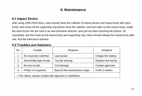
6.1 Impact Device After using 1000-2000 times, users should clean the catheter of impact device and impact body with nylon brush, and screw off the supporting ring before clean the catheter, and then take out the impact body, rotate the nylon brush into the tube in an anti-clockwise direction, and pull out when touching the bottom. So repeatedly, and then load up the impact body and supporting ring; Users should release the impact body after use. And the lubricant is banned. 6.2 Troubles and Solutions
No. Trouble Reasons Solutions
1 No response switched Lack power Charge the battery
2 Abnormally high results Test tip wearing Replace the test tip
3 No test results Coil damage Contact agencies
4 Printer no response Beyond the transmission range In the 3 meters
*The others, please contact with agencies or distributor.
18
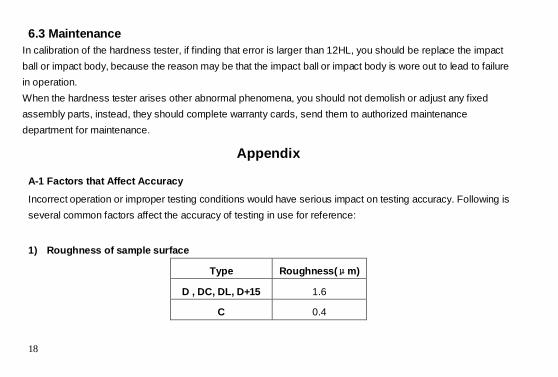
6.3 Maintenance In calibration of the hardness tester, if finding that error is larger than 12HL, you should be replace the impact ball or impact body, because the reason may be that the impact ball or impact body is wore out to lead to failure in operation. When the hardness tester arises other abnormal phenomena, you should not demolish or adjust any fixed assembly parts, instead, they should complete warranty cards, send them to authorized maintenance department for maintenance.
Appendix
A-1 Factors that Affect Accuracy
Incorrect operation or improper testing conditions would have serious impact on testing accuracy. Following is several common factors affect the accuracy of testing in use for reference:
1) Roughness of sample surface
Type Roughness(μm)
D , DC, DL, D+15 1.6
C 0.4
19
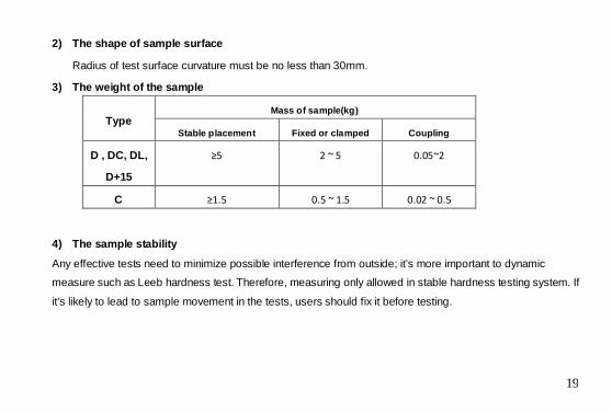
2) The shape of sample surface
Radius of test surface curvature must be no less than 30mm.
3) The weight of the sample
Type Mass of sample(kg)
Stable placement Fixed or clamped Coupling
D , DC, DL,
D+15
≥5 2 ~ 5 0.05~2
C ≥1.5 0.5 ~ 1.5 0.02 ~ 0.5
4) The sample stability
Any effective tests need to minimize possible interference from outside; it’s more important to dynamic
measure such as Leeb hardness test. Therefore, measuring only allowed in stable hardness testing system. If
it’s likely to lead to sample movement in the tests, users should fix it before testing.