Portable Digital Radiography and Computed Tomography Manual/67531/metadc... · Portable Digital...
132
The INL is a U.S. Department of Energy National Laboratory operated by Battelle Energy Alliance INL/EXT-07-12542 Portable Digital Radiography and Computed Tomography Manual Robert J. Pink Timothy J. Roney Mike Smith Karen Wendt Timothy A. White November 2007
Transcript of Portable Digital Radiography and Computed Tomography Manual/67531/metadc... · Portable Digital...

The INL is a U.S. Department of Energy National Laboratory operated by Battelle Energy Alliance
INL/EXT-07-12542
Portable Digital Radiography and Computed Tomography Manual
Robert J. Pink Timothy J. Roney Mike Smith Karen Wendt Timothy A. White
November 2007


INL/EXT-07-12542
Portable Digital Radiography and Computed Tomography Manual
Robert J. Pink Timothy J. Roney
Mike Smith Karen Wendt
Timothy A. White
November 2007
Idaho National Laboratory Idaho Falls, Idaho 83415
Prepared for the U.S. Department of Defense, U.S. Army
and for the U.S. Department of Energy
Under DOE Idaho Operations Office Contract DE-AC07-05ID14517


Portable Digital Radiography and Computed Tomography Manual
INL/EXT-07-12542
November 2007


v
SUMMARY
This user manual describes the function and use of the portable digital radiography and computed tomography (DRCT) scanner. The manual gives a general overview of x-ray imaging systems along with a description of the DRCT system. An inventory of the all the system components, organized by shipping container, is also included. In addition, detailed, step-by-step procedures are provided for all of the exercises necessary for a novice user to successfully collect digital radiographs and tomographic images of an object, including instructions on system assembly and detector calibration and system alignment. There is also a short section covering the limited system care and maintenance needs. Descriptions of the included software packages, the DRCT Digital Imager used for system operation, and the DRCT Image Processing Interface used for image viewing and tomographic data reconstruction are given in the appendixes. The appendixes also include a cheat sheet for more experienced users, a listing of known system problems and how to mitigate them, and an inventory check-off sheet suitable for copying and including with the machine for shipment purposes.

vi

vii
CONTENTS
SUMMARY.................................................................................................................................................. v
1. INTRODUCTION...........................................................................................................................1-1
1.1 X-Ray Imaging Systems.....................................................................................................1-1
1.2 DRCT System Description .................................................................................................1-3
2. DRCT SYSTEM PARTS LIST BY SHIPPING CONTAINER .....................................................2-1
2.1 Gantry Shipping Box..........................................................................................................2-1
2.2 X-Ray Generator Shipping Box .........................................................................................2-2
2.3 X-Ray Controller Shipping Box.........................................................................................2-2
2.4 X-Ray Detector Shipping Box............................................................................................2-3
2.5 Rotation Stage Shipping Box .............................................................................................2-4
2.6 Remote Computer Carrying Case and Other Loose Items .................................................2-5
3. FIRST TIME USERS GUIDE FOR DRCT SYSTEM OPERATION............................................3-1
3.1 Precautions and Pre-setup...................................................................................................3-1
3.2 DRCT Scanner Assembly...................................................................................................3-2
3.3 System Startup..................................................................................................................3-15
3.4 X-Ray Generator Warm-Up .............................................................................................3-19
3.5 Detector Calibration .........................................................................................................3-21
3.6 Digital Radiography .........................................................................................................3-31
3.7 Computed Tomography....................................................................................................3-38
3.8 System Shutdown .............................................................................................................3-48
4. SYSTEM CARE AND MAINTENANCE......................................................................................4-1
4.1 Lubrication .........................................................................................................................4-1
4.2 Bolts....................................................................................................................................4-1
4.3 Cables .................................................................................................................................4-1
Appendix A—DRCT Digital Imager ........................................................................................................A-1

viii
Appendix B—DRCT Image Processing Interface .................................................................................... B-1
Appendix C—Cheat Sheet to DRCT System Use .................................................................................... C-1
Appendix D—Known System Errors and Troubleshooting .....................................................................D-1
Appendix E—DRCT Inventory Checklist ................................................................................................ E-1
FIGURES
Figure 1-1. When collecting a radiograph, the source and LDA simultaneously scan past a stationary object. When collecting a tomography, the object rotates between a stationary source and LDA...............................................................................................................................1-2
Figure 1-2. Example of a digital radiograph. The left image is a “positive” (darker pixel intensity implies higher density or longer path lengths). The right image is a “negative” (lighter pixel intensity implies higher density or longer path lengths). The object is a pristine 4.2” mortar inside a multiple round container (MRC). ...........................................................................1-2
Figure 1-3. DRCT Gantry with x-ray generator, detector, and rotational stage installed. .........................1-3
Figure 1-4. Radiograph (left) and tomographic slices (middle and right) of a recovered World War I fuse. Note the line through each CT slice represents the point where the neighboring slice cuts the image..........................................................................................................................1-5
Figure 2-1. Gantry shipping box. ...............................................................................................................2-1
Figure 2-2. X-ray generator shipping box..................................................................................................2-2
Figure 2-3. X-ray controller shipping box. ................................................................................................2-3
Figure 2-4. X-ray detector shipping box. ...................................................................................................2-4
Figure 2-5. Rotation stage shipping box. ...................................................................................................2-5
Figure 2-6. Remote computer carrying case and other loose items, which include two remote safety boxes, four cable reels, and CT calibration phantom............................................................2-6
Figure 3-1. Remote safety boxes................................................................................................................3-2
Figure 3-2. Wheel installation....................................................................................................................3-3
Figure 3-3. Folding out extension arms. ....................................................................................................3-3
Figure 3-4. Setting of tilt feet.....................................................................................................................3-4
Figure 3-5. Connecting the rotation motor bypass module........................................................................3-5
Figure 3-6. Installing the rotation stage. ....................................................................................................3-5
ix
Figure 3-7. Connecting the rotation stage motor power. ...........................................................................3-6
Figure 3-8. Installing the detector. .............................................................................................................3-6
Figure 3-9. Properly seated detector. .........................................................................................................3-7
Figure 3-10. Installing the x-ray generator cradle......................................................................................3-7
Figure 3-11. Installing the x-ray generator. ...............................................................................................3-8
Figure 3-12. Connecting the motor control cable to the gantry. ................................................................3-8
Figure 3-13. Electrical box front................................................................................................................3-9
Figure 3-14. Connecting the x-ray control/safety circuit cable bundle to the x-ray generator and hanging cables. ..............................................................................................................................3-10
Figure 3-15. X-ray controller cable connectors. ......................................................................................3-10
Figure 3-16. Front door of the electrical box. ..........................................................................................3-11
Figure 3-17. Detector connectors.............................................................................................................3-12
Figure 3-18. X-ray controller ground lug.................................................................................................3-12
Figure 3-19. Safety circuit diagram. ........................................................................................................3-13
Figure 3-20. Terminating plug. ................................................................................................................3-13
Figure 3-21. Back of electrical box..........................................................................................................3-14
Figure 3-22. DRCT Digital Imager GUI..................................................................................................3-16
Figure 3-23. DRCT Image Processing Interface GUI..............................................................................3-17
Figure 3-24. Rotate stage pop-up.............................................................................................................3-17
Figure 3-25. Home motors pop-up...........................................................................................................3-18
Figure 3-26. Position stages window. ......................................................................................................3-18
Figure 3-27. Home status pop-up.............................................................................................................3-18
Figure 3-28. Installing solid plug.............................................................................................................3-19
Figure 3-29. X-ray controller. ..................................................................................................................3-20
Figure 3-30. Virtual x-ray controller........................................................................................................3-20
Figure 3-31. Installing slotted plug. .........................................................................................................3-21
Figure 3-32. Slotted plug alignment. .......................................................................................................3-22

x
Figure 3-33. Detector readout rate dialog box. ........................................................................................3-23
Figure 3-34. Offset set. ............................................................................................................................3-24
Figure 3-35. Some detectors saturated. ....................................................................................................3-25
Figure 3-36. All detectors unsaturated. ....................................................................................................3-25
Figure 3-37. Gain set example. ................................................................................................................3-26
Figure 3-38. Progress bar. ........................................................................................................................3-27
Figure 3-39. Dark trace. ...........................................................................................................................3-27
Figure 3-40. Sample dark image. .............................................................................................................3-28
Figure 3-41. Collect light data where there are no obstructions between the x-ray generator and detector. .........................................................................................................................................3-28
Figure 3-42. X-ray warning dialog box. ..................................................................................................3-29
Figure 3-43. Light trace. ..........................................................................................................................3-29
Figure 3-44. Sample light image..............................................................................................................3-30
Figure 3-45. Comparing dark files. ..........................................................................................................3-31
Figure 3-46. Installing object on rotate stage...........................................................................................3-32
Figure 3-47. Setting scan type from system parameters box. ..................................................................3-32
Figure 3-48. Positioning setup window. ..................................................................................................3-33
Figure 3-49. Send stage to start position pop-up......................................................................................3-34
Figure 3-50. DRCT Image Processing Interface......................................................................................3-35
Figure 3-51. Image input window............................................................................................................3-36
Figure 3-52. Sample radiograph of motor................................................................................................3-37
Figure 3-53. Operator comments window. ..............................................................................................3-37
Figure 3-54. Measuring height for collecting CT data.............................................................................3-38
Figure 3-55. Measurement result pop-up. ................................................................................................3-38
Figure 3-56. Positioning setup window. ..................................................................................................3-39
Figure 3-57. Sample sinogram of a motor. ..............................................................................................3-40
Figure 3-58. Installing CT calibration phantom.......................................................................................3-41

xi
Figure 3-59. Sample calibration sinogram. ..............................................................................................3-42
Figure 3-60. Calculate alignment parameters window. ...........................................................................3-43
Figure 3-61. Compare alignment parameters...........................................................................................3-44
Figure 3-62. Accept or decline new alignment parameters pop-up. ........................................................3-44
Figure 3-63. CT reconstruction input window.........................................................................................3-45
Figure 3-64. Sample CT slice of motor....................................................................................................3-46
Figure 3-65. Choosing region of interest. ................................................................................................3-47
Figure 3-66. Sample fine grid reconstruction. .........................................................................................3-48
Figure 3-67. Breakdown pop-up. .............................................................................................................3-48
Figure 3-68. Shutdown DRCT computer icon. ........................................................................................3-48

xii

xiii
ACRONYMS
2-D two dimensional
3-D three dimensional
ALARA As Low as Reasonably Achievable
CT computed tomography
DRCT digital radiography and computed tomography
GUI graphical user interface
LAN local area network
LDA linear detector array
MRC multiple round container
PCI I/O peripheral component interconnect input/output

xiv
1-1
Portable Digital Radiography and Computed Tomography Manual
1. INTRODUCTION
The system described in this manual provides the user with the capability to perform digital radiography and computed tomography (DRCT) of munitions in field situations or in a permanent location. The DRCT system represents an advance in technology from previous systems that were either film-based or used real-time video to acquire an image. This manual provides the user with the knowledge and directions to acquire high-quality, two-dimensional (2-D) radiographs and 2-D tomographic images.
Throughout this manual, nomenclature used to describe software operations will be as follows:
1. Commands in square brackets, [COMMAND], refer to buttons to be selected in the various windows
2. Commands in a string, Command>Command, refer to drop down items in the menu bar.
1.1 X-Ray Imaging Systems
An x-ray radiograph is a 2-D projection of a three-dimensional (3-D) object onto an image plane. An x-ray tomograph is a cross-sectional view of a 3-D object as if the object was sliced in two and viewed at the cutting plane. Radiographs and tomographs can be collected in a variety of geometries. The geometries shown in Figure 1-1, depicts those employed by the DRCT Scanner. An x-ray source and linear detector array (LDA) scan vertically past a stationary object when acquiring a radiograph, and a rotating object sits between a stationary x-ray source and LDA when acquiring a tomograph. There are many variations in the types of sources, detectors, and motions used to collect image data. In an ideal situation, the detector records only the radiation that has passed through the object without interaction with the object. Radiation that is attenuated (absorbed or scattered) by the object would not arrive at the detector and radiation that has scattered in the detector would be rejected by the detector. Radiation that must travel through greater material thickness or through higher density material is attenuated more than radiation that travels through shorter paths or lower density material. Thus, the intensity of radiation arriving at the detector is lower for greater material thickness (longer paths) or higher densities in the object and the intensity is higher for short paths or lower densities in the object. The relative difference in x-ray intensity through different parts of the object is displayed as a difference in pixel intensity in the corresponding image. The image may be displayed as a “positive” (longer path lengths though the same material appear darker than shorter ones) or a “negative” (longer path lengths are displayed brighter than shorter ones), as shown in Figure 1-2, but the information contained in the image is the same.

1-2
Figure 1-1. When collecting a radiograph, the source and LDA simultaneously scan past a stationary object. When collecting a tomography, the object rotates between a stationary source and LDA.
Figure 1-2. Example of a digital radiograph. The left image is a “positive” (darker pixel intensity implies higher density or longer path lengths). The right image is a “negative” (lighter pixel intensity implies higher density or longer path lengths). The object is a pristine 4.2” mortar inside a multiple round container (MRC).
Film-based imaging and video-based imaging both rely on detectors that acquire data over a large area in a single exposure. While this is convenient for some objects, it can be an extreme disadvantage for high-density objects such as most munitions. Detection of scattered photons decreases image contrast. Image quality is also compromised when detector elements are saturated. Saturation occurs when a detection element receives more radiation than it is able to record. The detector element is unable to respond to higher radiation flux and records a signal that reflects a lower than actual flux at the detector. The signal from saturated detector elements may spread to neighboring elements, leading to an image artifact called bleeding. These neighboring elements display a higher intensity than should be reflected by the actual x-ray flux. Saturation and bleeding often occur in regions of an image corresponding to detector elements that are exposed to an unattenuated beam. The shape of most munitions leads to a large number of saturated elements whose intensity bleeds into a region of interest in the image.

1-3
The DRCT system provides several benefits for imaging munitions. Two of the major changes in the DRCT system compared with previous systems are a collimated linear detector array and high-dynamic-range electronics. The collimation of the linear array eliminates almost all scatter arriving at the detector and the high-dynamic-range electronics provide for much greater contrast than the video-based systems. In comparison to an area-detector-based system, a system using a linear array collects one row of an image at a time. For a radiation source, the DRCT system uses a portable x-ray generator rather than radioactive material. To collect an entire image, the x-ray generator and detector must be scanned past the object.
1.2 DRCT System Description
The DRCT system consists of six major components, which are described in this section. A photo of the first four components set up to image a prop-charge can is shown in Figure 1-3.
Figure 1-3. DRCT Gantry with x-ray generator, detector, and rotational stage installed.
1. The wheeled gantry, which contains a vertical-translation stage (carriage), is the main system component; the rotate stage, x-ray generator, and detector are mounted to the gantry when the system is set up. The gantry extension arms are equipped with flip out feet which tilt the system to approximately 10 . The object, x-ray generator, and detector are all tilted; thus, images acquired with and without the tilt mechanism will be identical except for any material that changes position as the system is tilted, such as a free liquids contained inside an object. The gantry can be easily wheeled around (like a two-wheel dolly) by one person. The wheels can be easily removed and the gantry can be folded flat for easy packing for shipping.

1-4
2. The x-ray generator, also referred to as an x-ray tubehead, is portable and capable of x-ray output up to 300-kVp and 3-mA, which is sufficient to image most objects contained in 7 to 9-inch MRCs. During setup, the x-ray generator is set in a cradle on the left-hand side of the gantry.
3. The x-ray detector, consists of an 18-inch, LDA with 1024 detector elements. The detector is collimated such that it is sensitive only to x-rays in a thin plane through the object and is mounted on the opposite side of the carriage from the x-ray generator.
4. The machine chuck and rotational stage is for holding and positioning the object. The rotational stage is mounted between the x-ray generator and detector and can hold objects up to 12 inches in diameter. The rotation capability is used to acquire multiple radiographs of an object from different viewing angles and for computed tomography (CT) image acquisition. The rotational stage and chuck are not required for radiographic image acquisition; by leaving the rotational stage and chuck off of the assembly, the fold out extension arms can “wrap around” immobile objects or objects with larger diameters.
5. The electronics box contains a computer, the motion control and detector electronics, and power supplies. This is the real control center of the system, as it communicates with all of the other components and processes all of the data. It is placed near the gantry during normal operation.
6. The laptop computer is connected to the electronics box via a network cable for remote control of the system during data acquisition. The laptop computer can be placed up to 300 feet from the imaging system. If the x-ray system is shielded properly, this should provide a sufficient distance to safely operate the x-ray generator without unnecessary radiation exposure to personnel.
There are two software packages included that are used to control the system and process all of the data.
1. The DRCT Digital Imager is used for acquiring all of the radiographic data. In doing so, this package is used to control the vertical and rotational motions, calibrate the detector, and control the x-ray generator. This package can display radiographic data and do simple image manipulations, such as image flipping and grey-level adjustment. Histograms and line profiles can also be displayed.
2. The DRCT Image Processing Interface is an IDLTM-based package used to process and display both radiographic and tomographic data sets. Image manipulations include image orientation (inverting vertically), grey-level adjustment, resizing, region-of-interest display, and grey level reversal. Histograms can be displayed and dimensional measurements can be determined from the images. Grey-level adjustment can be performed from the histograms, as well as numerical parameter adjustment, giving the operator a more intuitive idea of what is actually being performed. This package also performs the DRCT System geometric calibrations necessary for proper data reconstruction and display of tomographic data sets.
The DRCT system is capable of 2-D projection radiography and 2-D and 3-D computed tomography imaging. For 2-D radiographic imaging, the x-ray generator and detector move synchronously past the object, building up an image one line at a time. For 2-D, single-slice tomography, the object rotates while the x-ray generator and detector remain stationary. For 3-D imaging, the x-ray generator and detector move vertically and the object rotates. From the object’s perspective, the x-ray generator and detector move in a spiral as 3-D data is collected.

1-5
Imaging times vary according to the desired resolution of the image and size and thickness of the object. A typical radiograph of a 7-inch diameter MRC can take from 20 seconds to 3 minutes. A 3-D computed tomography image of a region approximately 100 mm tall may take about 15 minutes to acquire. A radiograph of a fuse on a munition in an MRC and a few slices from a 3-D reconstruction of that same object are shown in Figure 1-4.
Radiograph 44 mm Vertical
Vertical Tomographic
SlicesHorizontal
Tomographic Slices
Figure 1-4. Radiograph (left) and tomographic slices (middle and right) of a recovered World War I fuse. Note the line through each CT slice represents the point where the neighboring slice cuts the image.

1-6
2-1
2. DRCT SYSTEM PARTS LIST BY SHIPPING CONTAINER
Following is a listing of all the components belonging to the DRCT system, grouped with their respective shipping containers.
2.1 Gantry Shipping Box
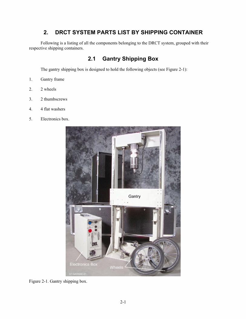
The gantry shipping box is designed to hold the following objects (see Figure 2-1):
1. Gantry frame
2. 2 wheels
3. 2 thumbscrews
4. 4 flat washers
5. Electronics box.
Figure 2-1. Gantry shipping box.

2-2
2.2 X-Ray Generator Shipping Box
The x-ray generator shipping box is designed to hold the x-ray generator (tubehead), Yxlon, model Smart 300 HD (see Figure 2-2).
Figure 2-2. X-ray generator shipping box.
2.3 X-Ray Controller Shipping Box
The x-ray controller shipping box is designed to hold the following objects (see Figure 2-3):
1. X-ray control console, Yxlon, model Smart 583
2. Console key
3. Gray accessories bag containing
a. 50-foot yellow power cable
b. Green/yellow ground cable
c. 10-foot remote safety cable
d. 50–230-foot remote safety cable
e. X-ray communication cable

2-3
f. Hub/laptop network cable (Cat. 5)
g. Network hub and power supply
h. Electrical box power cord
i. Spare fuses/lamps package
j. Solid lead plug
k. Slotted lead plug with two copper filtration disks (1 mm each)
l. Small flathead screwdriver
4. Two radiation survey meters, Victoreen, model 451B-RYR.
Figure 2-3. X-ray controller shipping box.
2.4 X-Ray Detector Shipping Box
The x-ray detector shipping box is designed to hold the detector assembly (see Figure 2-4). The LDA inside the assembly is a Thales model number TH 9599 400.

2-4
Figure 2-4. X-ray detector shipping box.
2.5 Rotation Stage Shipping Box
The rotation stage shipping box is designed to hold the following objects (see Figure 2-5):
1. Rotation stage assembly
2. Accessory jaws box
a. Three steel jaws
b. Three plastic jaws
c. Three steel, long extension jaws
d. Allen wrench
3. Standard chuck key and/or speed wrench chuck key
4. Tubehead cradle.

2-5
Figure 2-5. Rotation stage shipping box.
2.6 Remote Computer Carrying Case and Other Loose Items
The remote computer carrying case is designed to hold the following objects (see Figure 2-6):
1. Laptop computer, Panasonic, model CF-51
2. USB mouse
3. Power supply and cord.
Other loose items include the following objects (see Figure 2-6):
1. Two remote safety boxes (including two keys and one terminating plug)
2. Four cable reels
a. Motor control
b. Detector (three-cable bundle)
c. Hub/electronics box network (Cat. 5)
d. X-ray control/safety circuit (two-cable bundle)
3. CT calibration phantom.

2-6
Figure 2-6. Remote computer carrying case and other loose items, which include two remote safety boxes, four cable reels, and CT calibration phantom.

3-1
3. FIRST TIME USERS GUIDE FOR DRCT SYSTEM OPERATION
This section of the manual is a detailed guide for setup and operation of the DRCT system and will be especially useful for first time users. This guide will take the user through system setup, startup, detector calibration, digital radiography data collection and image display, computed tomography data acquisition and image reconstruction, and system shutdown. These are the basic operations that are performed routinely when using the DRCT system.
This guide alone is not sufficient enough to provide users with a complete knowledge of all of the capabilities of the DRCT Imaging System. For that, a lot of practice and exploring of the different software commands is necessary. Following this guide will enable the operator to quickly and easily obtain high-quality radiographs and CT slices of an object.
Software descriptions for the DRCT Imaging System, including where the commands are located, can be found in Appendices A and B. For more experienced users, including those who have not operated the system recently and simply need to review and those familiar with older DRCT versions, a shorter, simpler cheat-sheet of the following guide is located in Appendix C.
3.1 Precautions and Pre-setup
WARNING
The DRCT system can generate a lethal x-ray dose. It is assumed that the operators of the system have been trained in radiation safety and the safe operation of x-ray generation devices and will take all necessary precautions to ensure the safety of all personnel and the public. If you have not had formal training in radiation safety and the operation of radiation generating equipment, do not attempt to operate the DRCT system.
1. When in use, the gantry and electrical box are set up either in an x-ray enclosure, or in a radiation area, and the laptop computer and x-ray controller will be set up in a separate operations area. When not using an x-ray enclosure, the radiation area and operations should be chosen for maximum radiation protection to personnel and the public. ALARA (As Low as Reasonably Achievable) principals must be followed. Any available shielding (temporary shielding panels, machinery, embankments, etc.) should be used. The x-ray generator must be pointed away from the operations area and/or any other areas to which personnel or the general public has access to.
For operation inside an x-ray enclosure, the gantry should be set up so that the x-ray generator is pointed away from the entry and toward the primary (thickest) shielding wall. For operation outside of x-ray enclosures, the gantry must be set up on a level area, as it may easily tip over when the x-ray generator and detector are near the top of the vertical travel range if not on a level surface.
Optimally, there should be 2 feet of clearance behind the wheels and maximum clearance around all other sides of the machine.

3-2
2. Two remote safety boxes (see Figure 3-1) are supplied with the DRCT scanner. Each remote safety box has an audible x-ray pre-warning alarm, a flashing red strobe that is energized when x-rays are generated, and an emergency-off button. There is also an emergency-off button located on the top of the DRCT gantry. When the remote safety boxes are used, they are wired in a series circuit with the gantry button. If any one button is depressed, the x-ray generator and the gantry motors are disabled. The remote safety boxes should be set up so that one is located near the DRCT scanner and the other is located near the entrance to the radiation area.
Figure 3-1. Remote safety boxes.
Use of the remote safety boxes is not necessary if the x-ray system is operated inside an x-ray enclosure and connected to the enclosure safety system.
3. Care must be taken when moving and assembling the DRCT equipment. Several components, most notably the x-ray generator and detector, are sensitive and fragile instruments. Other components are heavy, and safe lifting techniques should be followed when they are being moved. Lifting the gantry into and out of its shipping container is a two-person task.
4. Make all electrical connections before powering up any equipment.
3.2 DRCT Scanner Assembly
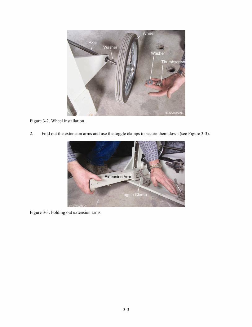
1. Install the wheels onto the gantry axle (see Figure 3-2). The installation order is as follows: flat washer, wheel, flat washer, and finally a thumbscrew to hold the assembly together. Repeat this for the other wheel.
3-3
Figure 3-2. Wheel installation.
2. Fold out the extension arms and use the toggle clamps to secure them down (see Figure 3-3).
Figure 3-3. Folding out extension arms.

3-4
3. Set the tilt feet to the appropriate position for the scan job (see Figure 3-4). The gantry should be tilted backwards when looking for evidence of liquids, and it should stand vertically otherwise.
Figure 3-4. Setting of tilt feet.
4. If the rotation stage is not going to be used, such as when an object is not easily movable, connect the rotation stage power lead (extending from the lower left gantry leg) to the rotate motor bypass module, which is tethered to the lower limit switches (see Figure 3-5). Go to Step 7, finish the scanner assembly, and move it into position such that the object is straddled with the scanner extension arms.

3-5
Figure 3-5. Connecting the rotation motor bypass module.
5. Install the rotation stage onto the extension arms by aligning the pins on the underside of the rotate frame with the holes in the extension arms and setting the stage down (see Figure 3-6). Secure the stage in place with the four tethered thumbscrews.
Figure 3-6. Installing the rotation stage.

3-6
6. Connect the rotation stage power lead (extending from the lower left gantry leg) to the rotation stage motor (see Figure 3-7).
Figure 3-7. Connecting the rotation stage motor power.
7. Install the detector assembly onto the pins located at the upper right side of the gantry carriage (see Figure 3-8). Make sure that the detector assembly hanger tab sits flat on the carriage (see Figure 3-9).
Figure 3-8. Installing the detector.

3-7
Figure 3-9. Properly seated detector.
8. Install the x-ray generator cradle onto the lower left side of the gantry carriage by aligning the pins on the backside of the cradle with the holes in the carriage (see Figure 3-10). Secure in place with the two tethered thumbscrews.
Figure 3-10. Installing the x-ray generator cradle.
9. Lay the x-ray generator in the cradle such that the x-ray port points toward the detector and the mounting-ring ears rest on the cradle pads located at the end of the cradle arms (see Figure 3-11). Secure in place with the two tethered thumbscrews. It may be necessary to rock the generator to get the thumbscrews to go in easily.

3-8
Figure 3-11. Installing the x-ray generator.
10. Connect the motor control cable between the connector located on the back of the left gantry leg (see Figure 3-12) and the J1 connector on the front of the electrical box (see Figure 3-13).
Figure 3-12. Connecting the motor control cable to the gantry.

3-9
Figure 3-13. Electrical box front.
11. Set up the laptop computer, network hub, and x-ray control console in the operations area.
12. Connect the short network cable between the local area network (LAN) ports on the back of the laptop and the network hub.
13. Connect the long network cable between the LAN ports on the electrical box (J2, see Figure 3-13) and the network hub.
14. Connect the control lead of the x-ray control/safety circuit cable bundle to the x-ray generator and clip the carabineer to the gantry handle (see Figure 3-14). Ensure that the cable will not catch on anything when the gantry carriage moves up and down.

3-10
Figure 3-14. Connecting the x-ray control/safety circuit cable bundle to the x-ray generator and hanging cables.
15. Connect the safety circuit lead of the x-ray control/safety circuit cable bundle to one of the remote safety connectors on the front of the electrical box (see Figure 3-13). It does not matter which of the two connectors is used.
16. Roll out the x-ray control/safety circuit cable bundle to the operations area and connect the two leads to the control and safety circuit connectors on the x-ray control console (see Figure 3-15).
Figure 3-15. X-ray controller cable connectors.
17. Connect the x-ray communication cable between the small round connector on the x-ray control console (see Figure 3.15) and the electrical box x-ray connector, located behind the front panel door (see Figure 3-16). Connector labels are printed on the back of the door.

3-11
Figure 3-16. Front door of the electrical box.
18. Connect the detector cable bundle between the detector power, communications, and peripheral component interconnect input/output (PCI I/O) connectors on the electrical box and the detector. The detector power connector is located on the front of the electrical box (see Figure 3-13). The detector communications and PCI I/O connectors are located behind the front door of the x-ray control console (see Figure 3-16). The detector connectors are located on the end of the detector that is away from the gantry (see Figure 3-17). These connectors are not labeled, but the connections can only be made in one configuration. Run the cable around the detector side of the gantry, clip the carabineer to the gantry handle (see Figure 3-14), and set the cable in the clips on top of the detector. Ensure that the cable will not catch on anything when the gantry carriage moves up and down.

3-12
Figure 3-17. Detector connectors.
19. Connect the green and yellow ground wire between the ground lug on the on the x-ray control console, located on the opposite end of the control console from the rest of the connectors (see Figure 3-18), and a suitable earth ground (such as plumbing or a ground stake).
Figure 3-18. X-ray controller ground lug.

3-13
20. Set up the remote safety boxes so that one is located near the DRCT scanner and the other is located near the entrance to the radiation area. The safety circuit should be wired according to the diagram in Figure 3-19 Connect the short remote safety cable between the remaining remote safety connector on the front of the electrical box (see Figure 3-13) and one of the connectors on the first remote safety box (see Figure 3-1). Connect the long remote safety cable between the two remote safety boxes. It does not matter which connectors are used. If more remote safety boxes are available, they can be daisy chained together in a similar fashion.
Figure 3-19. Safety circuit diagram.
21. Complete the safety circuit by connecting the terminating plug (see Figure 3-20) to the unused connector on the last remote safety box.
Figure 3-20. Terminating plug.

3-14
22. Connect a power cord between the power plug on the back of the electrical box (see Figure 3-21) and a 120V AC outlet. The fans in the electrical box should start once it is plugged in.
Figure 3-21. Back of electrical box.
23. Connect power cords between the network hub and, if necessary, the laptop computer and a 120V AC outlet.

3-15
24. Connect the yellow x-ray power cable between the x-ray control console power connector (see Figure 3-15) and a 120V AC power outlet.
25. Ensure that no obstructions will block free movement of the x-ray generator or detector and that their respective cables have the proper slack for translation without getting caught on anything.
26. If one is available, set up the video camera to monitor the gantry and radiation area. Connect the camera to a monitor in the operations area so that the system and surrounding area can be observed during scanning.
3.3 System Startup
1. Start the electrical box computer and laptop. The electrical box computer on/off switch is inside the door on the back of the electrical box (see Figure 3-21).
2. Wait 2 or 3 minutes for the electrical box computer to establish communications with the network hub.
3. Log on to the laptop computer. The DRCT system username and password are both “mmas.”
4. Double click on the “Connect to Gantry.RDP” icon on the laptop to establish communications with the computer in the electrical box, and enter the DRCT system password when prompted. The desktop for the electrical box computer will appear on the laptop screen. The DRCT Digital Imager(see Figure 3-22) should start automatically. Also, an IDLTM Applications window will open. Clicking on the IDLTM Applications window will start the DRCT Image Processing Interface (see Figure 3-23). If these software packages have not been launched automatically, double click on the appropriate icons on the desktop to start them.

3-16
Figure 3-22. DRCT Digital Imager GUI.

3-17
Figure 3-23. DRCT Image Processing Interface GUI.
5. A pop-up window (see Figure 3-24) from the DRCT Digital Imager software will ask if the rotate stage is connected. Click on [Yes] if the rotate stage is connected, and click on [NO] if the rotate motor bypass module is connected. Giving the wrong answer can hang up the system such that the only cure is to use the task manager to shutdown the DRCT Digital Imager software and restart it.
To change between using the rotation stage or not, the DRCT Imaging gantry must be powered down to eliminate any chances of electrical damage to the rotation motor or the motion control electronics. Upon powering back up, the DRCT Digital Imager software must be re-launched, and the rotate stage connection pop-up answered correctly to get the software working properly.
Figure 3-24. Rotate stage pop-up.

3-18
6. A second pop-up window will warn that the motors need to be homed (see Figure 3-25). Click on [Home] and the POSITION STAGES window will appear (see Figure 3-26). In the lower left corner, click on [HOME ALL], then in the HOME STATUS pop-up window (see Figure 3-27) click on [HOME MOTORS?] to initiate the action. The rotate and vertical motors will find their home positions (0o and 0 mm) and a message should appear in the pop-up window for verification. If the message does not appear within a couple of minutes, click on [HOME MOTORS?] again. Click on [CLOSE] to close the pop-up window, and File>Return to close the POSITION STAGES window.
Figure 3-25. Home motors pop-up.
Figure 3-26. Position stages window.
Figure 3-27. Home status pop-up.
3-19
3.4 X-Ray Generator Warm-Up
WARNING
Throughout the rest of this procedure lethal x-ray doses will be produced. It is the operator’s responsibility to ensure that the radiation area is clear of all personnel prior to system start up.
Whenever the radiation area is entered, the x-ray controller key must be carried into it to prevent accidental startup, and all of the remote safety buttons must be depressed on the way in. A working radiation survey meter must be carried into the radiation area to ensure that the radiation producing devices are indeed off in order to eliminate the chances for accidental radiation exposure. To restart x-rays, the person with the key must reset the remote safety buttons from inside the radiation area outwards, all the while clearing the radiation area of personnel.
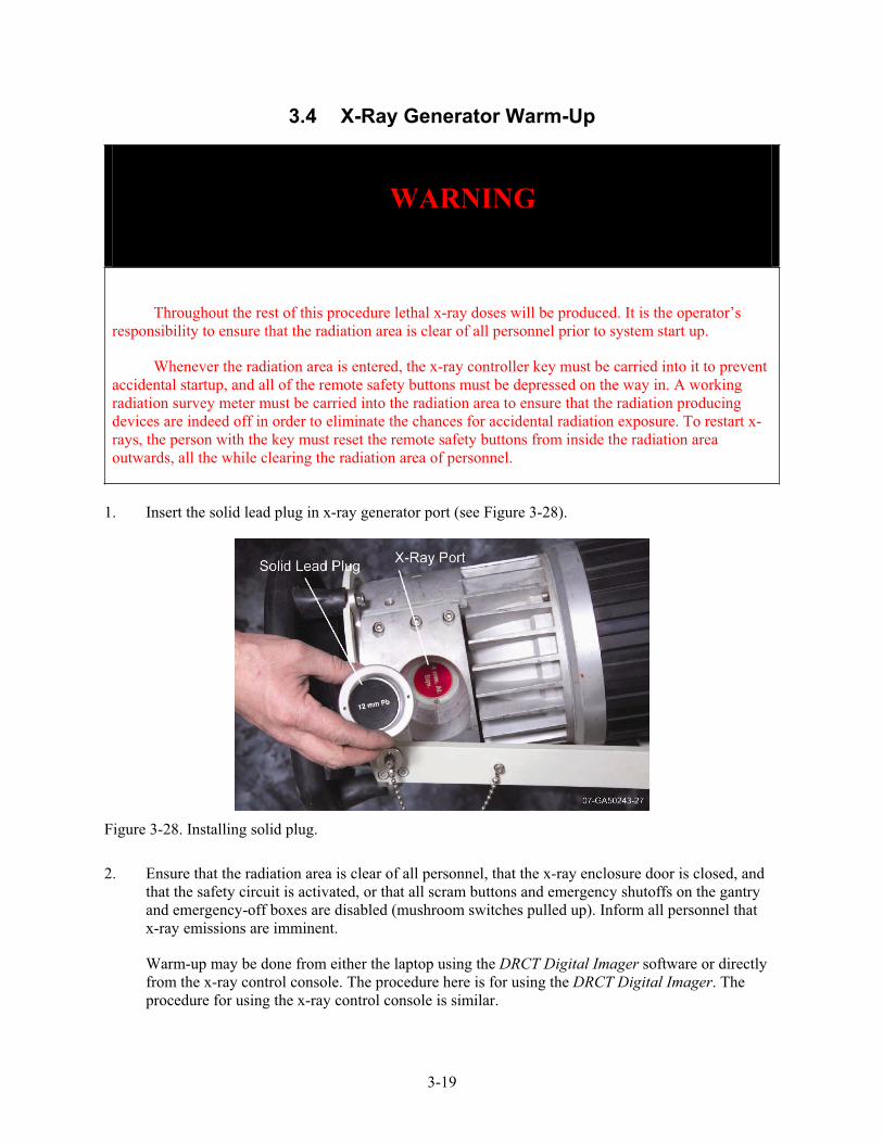
1. Insert the solid lead plug in x-ray generator port (see Figure 3-28).
Figure 3-28. Installing solid plug.
2. Ensure that the radiation area is clear of all personnel, that the x-ray enclosure door is closed, and that the safety circuit is activated, or that all scram buttons and emergency shutoffs on the gantry and emergency-off boxes are disabled (mushroom switches pulled up). Inform all personnel that x-ray emissions are imminent.
Warm-up may be done from either the laptop using the DRCT Digital Imager software or directly from the x-ray control console. The procedure here is for using the DRCT Digital Imager. The procedure for using the x-ray control console is similar.

3-20
3. Insert the key into the x-ray control console and turn it to the on (I) position (see Figure 3-29). The bottom readout window will list the time required for generator warm-up.
Figure 3-29. X-ray controller.
4. From the DRCT Digital Imager software, click the [X-RAY SOURCE] button. The virtual x-ray generator control panel will open on the screen (see Figure 3-30). Notice how the virtual and actual control panels look very similar. All of the functions available here look and act very much the same as they do on the real x-ray controller.
NOTE: The virtual x-ray controller is not a substitute for the real controller. Rather, the virtual controller controls the real controller. It is good practice when using the virtual controller to monitor the actual controller to ensure that it is operating properly. It is especially important to check the actual controller when shutting down x-rays and to remove the actual key and use a survey meter when approaching the x-ray generator.
Figure 3-30. Virtual x-ray controller.

3-21
5. In the lower right of the virtual control panel, set the kV and mA to maximum (300 kV and 3.0 mA).
6. Just above the kV and mA settings, turn the virtual key switch from the SAFE to the ON position.
7. Click on the GREEN button to start the warm-up. The top readout on the actual controller will display the warm-up time remaining and the current kV and mA levels. The kV and mA will slowly increase to their maximum values and then the generator will run at that level for a few minutes. Warm-up could take as long as 32 minutes, depending on how long it has been since the generator was last operated. The x-ray generator will automatically shut down when the warm-up is complete. Click on the RED button to terminate x-rays.
If for any reason the x-rays need to be shut down, push the RED button on either the virtual control panel or the x-ray control console.
8. To exit the virtual x-ray generator control panel, click on File>Return.
9. Turn the x-ray controller key to the standby position (~) and remove it.
3.5 Detector Calibration
1. Switch the solid lead plug in the x-ray generator port with the slotted lead plug with the copper filter (see Figure 3-31). Make sure that the plug slot is inserted so that it is aligned with the detector collimator. Note that the screw holes on the front of the plug are oriented perpendicular to the slot, and that they can be lined up with the alignment mark in the tube port to get the slotted plug inserted correctly (see Figure 3-32).
Figure 3-31. Installing slotted plug.

3-22
Figure 3-32. Slotted plug alignment.
2. Set the detector readout frequency.
a. From the DRCT Digital Imager menu bar, click on Detector>Detector Setup.
b. In the SET READOUT RATE window (see Figure 3-33), choose one of the three readout rate options from the Detector Parameters drop down menu.
(1) 40 Hz, 20 mSec is the default setting, which will be used for most objects.
(2) 60 Hz, 13 mSec should be used for very low density or short path length objects.
(3) 10 Hz, 80 mSec should be used for very high density or long path length objects.

3-23
Figure 3-33. Detector readout rate dialog box.
c. Click on [RESET] and new actual parameters will be calculated to confirm that the readout option is accepted. Click on [OK] to close the SET READOUT RATE window.
3. Set the detector offset (x-rays off) and gain (x-rays on).
NOTE 1: The offset and gain calibrations must be performed each time the detector readout rate is reset.
NOTE 2: There must be nothing blocking the x-rays from the detector to set the gain properly. If an object has been placed in the rotate stage chuck, then the generator and detector must be moved above it. If the motors are still in the home position, then the chuck is high enough to block the detector.
a. Click on the [X-RAY SOURCE] button to reopen the virtual x-ray controller.
b. From the x-ray control panel menu bar, click Calibration>Offset. The SET OFFSET window with a virtual oscilloscope and a set of disabled (grayed out) kV and mA adjustment buttons will open (see Figure 3-34). The flat trace on the screen represents the detector output signal across the length of the detector array.

3-24
Figure 3-34. Offset set.
c. Click on the [SET OFFSET] button. The offset calibration is finished when the “Normal Mode” indication appears in the lower portion of the oscilloscope.
d. Click on [CLOSE].
e. Insert the key into the real x-ray control console and turn it to the on (I) position.
f. From the virtual x-ray control console, start the x-ray generator by clicking on the GREENbutton and let it come up to full power.
g. From the x-ray control panel menu bar, click Calibration>Offset again. The SET OFFSET window reopens, this time with the kV and mA control buttons enabled. The trace on the screen shows that x-rays are now being detected, but the output is not even across the detector. Notice that some detector sections are saturated as represented by flat sections in the trace at the maximum level (see Figure 3-35).

3-25
Figure 3-35. Some detectors saturated.
h. Adjust the generator kV and mA until the whole trace is just below saturation (see Figure 3-36) by using the kV and mA increase and decrease buttons. Do not click on these buttons rapidly, as doing so will only confuse and lock up the system. Table 3-1 lists kV and mA values that generally work well with the different readout rate options. These are not the only possible settings that will work.
Figure 3-36. All detectors unsaturated.

3-26
Table 3-1. kV and mA values that work well with different readout rate options.
Readout Rate kV mA
60 Hz, 13 mSec 260 2.5
40 Hz, 20 mSec 200 2.7
10 Hz, 80 mSec 175 0.9
i. Make note of the kV and mA settings that are actually displayed on the real x-ray controller. Close the SET OFFSET window and turn off the x-ray generator by clicking on the REDbutton.
j. On the virtual x-ray generator control panel, enter the gain settings just determined in the kV and mA boxes. Start the x-rays and wait until the readout window on the virtual x-ray controller displays these same kV and mA settings, which indicates that the x-ray generator is operating at the desired gain settings.
k. From the x-ray control panel menu bar, click Calibration>Gain. The SET GAIN window opens with the unsaturated trace in the virtual oscilloscope.
l. Click on the [SET GAIN] button. The gain calibration is finished when the “Normal Mode” indication appears and the oscilloscope trace flattens out (see Figure 3-37).
Figure 3-37. Gain set example.
m. Click on [CLOSE].
n. Turn off the x-ray generator and exit the virtual x-ray generator control panel.
3-27
4. Collect dark (x-rays off) and light (x-rays on with no object between the generator and detector) images.
NOTE: Dark and light images should be collected a few times per day, as temperatures vary, though it is not necessary to collect them for each object.
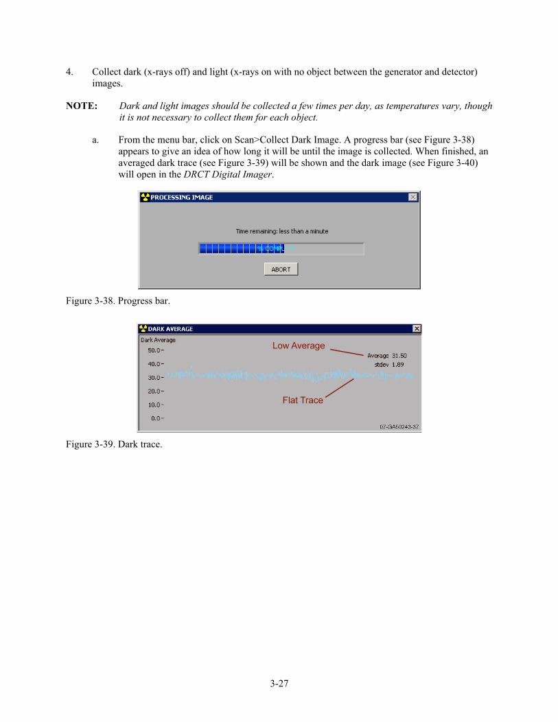
a. From the menu bar, click on Scan>Collect Dark Image. A progress bar (see Figure 3-38) appears to give an idea of how long it will be until the image is collected. When finished, an averaged dark trace (see Figure 3-39) will be shown and the dark image (see Figure 3-40) will open in the DRCT Digital Imager.
Figure 3-38. Progress bar.
Figure 3-39. Dark trace.
3-28
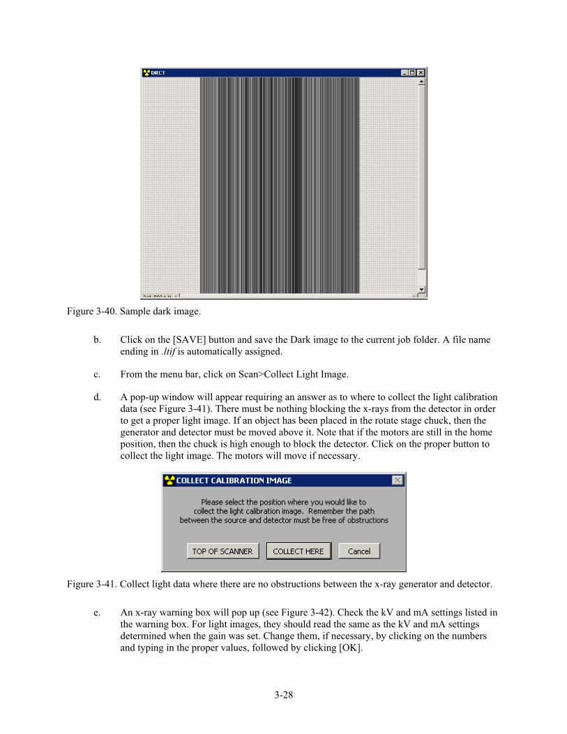
Figure 3-40. Sample dark image.
b. Click on the [SAVE] button and save the Dark image to the current job folder. A file name ending in .ltif is automatically assigned.
c. From the menu bar, click on Scan>Collect Light Image.
d. A pop-up window will appear requiring an answer as to where to collect the light calibration data (see Figure 3-41). There must be nothing blocking the x-rays from the detector in order to get a proper light image. If an object has been placed in the rotate stage chuck, then the generator and detector must be moved above it. Note that if the motors are still in the home position, then the chuck is high enough to block the detector. Click on the proper button to collect the light image. The motors will move if necessary.
Figure 3-41. Collect light data where there are no obstructions between the x-ray generator and detector.
e. An x-ray warning box will pop up (see Figure 3-42). Check the kV and mA settings listed in the warning box. For light images, they should read the same as the kV and mA settings determined when the gain was set. Change them, if necessary, by clicking on the numbers and typing in the proper values, followed by clicking [OK].

3-29
Figure 3-42. X-ray warning dialog box.
f. The virtual x-ray generator control panel will then reopen and a second chance to change the kV and mA is available, if necessary. Click on the GREEN button to start x-rays and collect the light image.
g. The progress bar will reappear. When finished, an averaged light trace (see Figure 3-43) will be shown, and the light image (see Figure 3-44) will open in the DRCT Digital Imager.
Figure 3-43. Light trace.

3-30
Figure 3-44. Sample light image.
h. Click on the [SAVE] button and save the light image to the current job folder. Again, the file name ending in .ltif is automatically assigned.
i. Use the DRCT Image Processing Interface to compare the dark and light images to the reference dark and light images. From the menu bar click Tools>Evaluate Light/Dark File.
j. In the file selection window, locate the dark/light file that was just saved in the current job folder and open it. The dark/light image will open along with a pair of plots of the average pixel intensities and standard-deviation of pixel intensities.
k. Repeat steps i and j to open the reference dark/light Files. They are stored in the Reference Files folder which can be found on the computer desktop.
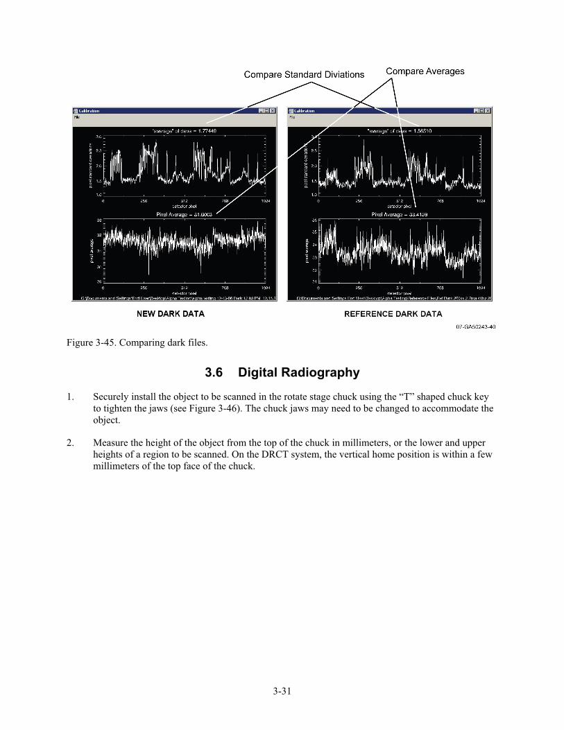
l. Compare the pairs of dark and light images. The standard deviations and pixel averages should be in rough agreement, as in the dark image comparison in Figure 3-45. If the images are not in rough agreement, re-shoot the dark and light images.
3-31
Figure 3-45. Comparing dark files.
3.6 Digital Radiography
1. Securely install the object to be scanned in the rotate stage chuck using the “T” shaped chuck key to tighten the jaws (see Figure 3-46). The chuck jaws may need to be changed to accommodate the object.
2. Measure the height of the object from the top of the chuck in millimeters, or the lower and upper heights of a region to be scanned. On the DRCT system, the vertical home position is within a few millimeters of the top face of the chuck.

3-32
Figure 3-46. Installing object on rotate stage.
3. In the System Parameters window of the DRCT Digital Imager, use the pull-down menu to set the scan type to RADIOGRAPH (see Figure 3-47).
Figure 3-47. Setting scan type from system parameters box.

3-33
4. Click on the [SCAN] button.
5. In the POSITIONING SETUP window (see Figure 3-48), set the scan start and finish heights by entering the measured values from Step 2. This can also be done by moving the slider bars. Note that it is possible to scan either upwards or downwards according as to which height is entered in the scan start and finish positions. Click on [OK].
Figure 3-48. Positioning setup window.
3-34
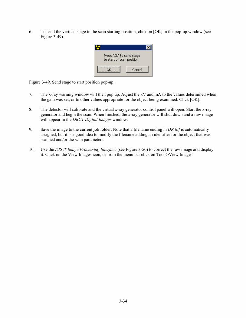
6. To send the vertical stage to the scan starting position, click on [OK] in the pop-up window (see Figure 3-49).
Figure 3-49. Send stage to start position pop-up.
7. The x-ray warning window will then pop up. Adjust the kV and mA to the values determined when the gain was set, or to other values appropriate for the object being examined. Click [OK].
8. The detector will calibrate and the virtual x-ray generator control panel will open. Start the x-ray generator and begin the scan. When finished, the x-ray generator will shut down and a raw image will appear in the DRCT Digital Imager window.
9. Save the image to the current job folder. Note that a filename ending in DR.ltif is automatically assigned, but it is a good idea to modify the filename adding an identifier for the object that was scanned and/or the scan parameters.
10. Use the DRCT Image Processing Interface (see Figure 3-50) to correct the raw image and display it. Click on the View Images icon, or from the menu bar click on Tools>View Images.

3-35
Figure 3-50. DRCT Image Processing Interface.
11. The window will display Image Input mode (see Figure 3-51). To have the software step through the process selecting the proper dark, light, and object files, check the boxes for the dark and light filenames. Click [Begin].

3-36
Figure 3-51. Image input window.
12. A series of three standard Windows TM file selection windows will pop-up. Read the prompts in the title bars to select the dark, light, or object file that is requested, and click [OK] to proceed to the next window in the proper order. It may be necessary to redirect the file selection windows to the current work folder. A corrected digital radiograph will open in a new window. Figure 3-52 is a sample radiograph of a motor that should give an idea of what should be expected.
Several things can be done at this point with the image to enhance viewing; most notably, it can be flipped over if it is upside down, it can be resized or magnified, the gray scales can be adjusted to make different features easier to see, and measurements may be taken. For a complete description of these operations, see Appendix B.

3-37
Figure 3-52. Sample radiograph of motor.
13. Save the corrected digital radiograph to the current job folder by selecting File>Export 8-Bit TIFF from the DRCT Image Processing Interface. The window will change to allow data input on the scan operation (Figure 3-53). Fill in the required data and observations in the proper fields, enter the radiographer’s name, and click on [Select A Name For The Output Tiff File]. Enter a filename.
You should now have a corrected digital radiograph of the object saved. To acquire tomographic data from the object, do not remove or reposition the object in the chuck.
Figure 3-53. Operator comments window.

3-38
3.7 Computed Tomography
1. With the corrected digital radiograph selected as the current window, click on Tools>Select CT Level>Single Slice from the menu bar of the DRCT Image Processing Interface.
2. Move the mouse cursor over the digital radiograph and it will change to a yellow line. The measured distance from the bottom of the image to the line is displayed in the lower left corner (see Figure 3-54). Click at the level of the object where it is desired to collect computed tomography (CT) data to freeze the measurement. A pop-up window will give the distance in both millimeters and inches (see Figure 3-55). If the lower level of the digital radiograph was not at zero (home position), then the lower level measured in Step 3.6.5, must be added to the distance just measured. Click [OK] to exit the CT level mode.
Figure 3-54. Measuring height for collecting CT data.
Figure 3-55. Measurement result pop-up.
3. In the System Parameters window of the DRCT Digital Imager (see Figure 3-47), set the scan type to CT SLICE.
3-39
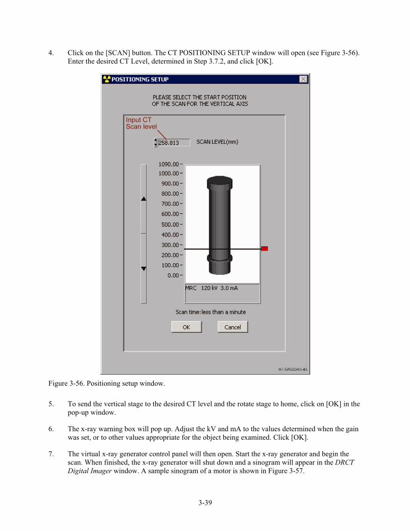
4. Click on the [SCAN] button. The CT POSITIONING SETUP window will open (see Figure 3-56). Enter the desired CT Level, determined in Step 3.7.2, and click [OK].
Figure 3-56. Positioning setup window.
5. To send the vertical stage to the desired CT level and the rotate stage to home, click on [OK] in the pop-up window.
6. The x-ray warning box will pop up. Adjust the kV and mA to the values determined when the gain was set, or to other values appropriate for the object being examined. Click [OK].
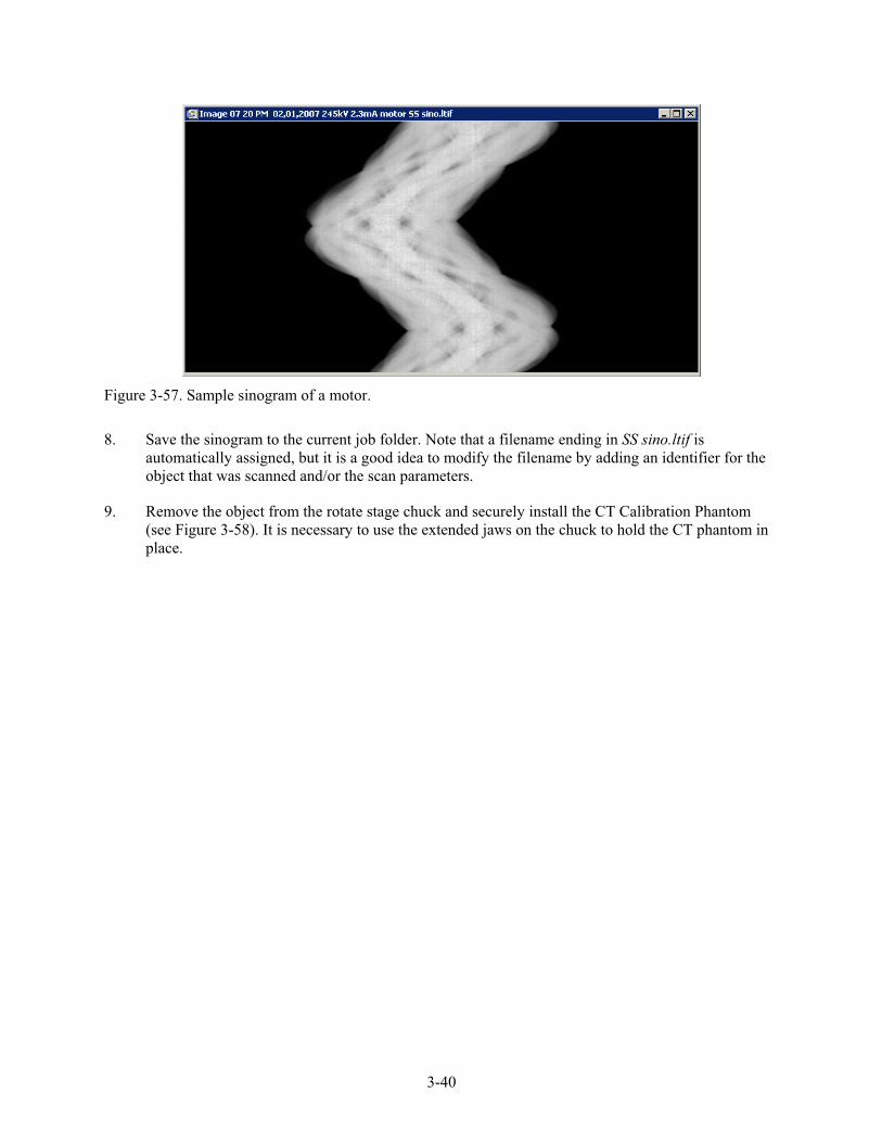
7. The virtual x-ray generator control panel will then open. Start the x-ray generator and begin the scan. When finished, the x-ray generator will shut down and a sinogram will appear in the DRCT Digital Imager window. A sample sinogram of a motor is shown in Figure 3-57.
3-40
Figure 3-57. Sample sinogram of a motor.
8. Save the sinogram to the current job folder. Note that a filename ending in SS sino.ltif is automatically assigned, but it is a good idea to modify the filename by adding an identifier for the object that was scanned and/or the scan parameters.
9. Remove the object from the rotate stage chuck and securely install the CT Calibration Phantom (see Figure 3-58). It is necessary to use the extended jaws on the chuck to hold the CT phantom in place.

3-41
Figure 3-58. Installing CT calibration phantom.
10. In the System Parameters window of the DRCT Digital Imager (see Figure 3-47), set the scan type to CALIBRATION CT.
11. Click on the [SCAN] button.
12. The POSITIONING SETUP window will reopen (see Figure 3-56). Set the scan level to the same CT level used to collect the object sinogram, determined in Step 3.7.2 and click on [OK].
13. To send the vertical and rotate stages to their start positions, click on [OK] in the pop-up window.
14. The x-ray warning box will pop up. Ensure that the kV and mA settings listed in the warning box read the same as the kV and mA settings determined when the gain was set. Click on [OK].

3-42
15. The virtual x-ray generator control panel will then open. Start the x-ray generator and begin the scan. When finished, the x-ray generator will shut down and a calibration sinogram will appear in the DRCT Digital Imager window. A sample calibration sinogram is shown in Figure 3-59.
Figure 3-59. Sample calibration sinogram.
16. Save the calibration sinogram to the current job folder. Note that a filename ending in CAL sino.ltifis automatically assigned, but it is a good idea to modify the filename by adding an identifier for the scan parameters.
17. From the menu bar in the DRCT Image Processing Interface, click Tools>Calculate Alignment Parameters, and check the boxes for dark and light corrections (see Figure 3-60). Click on [Open].

3-43
Figure 3-60. Calculate alignment parameters window.
18. In the next three file selection windows that pop-up, read the prompts in the title bars to select the dark, light, and object files in the proper order.
19. Compare the calculated alignment parameters to the current parameters settings in the DRCT Image Processing Interface. If the parameters are in reasonable agreement, as they are in Figure 3-61, click on [Yes] in the question pop-up window (see Figure 3-62) to accept them. If these parameters are not acceptable, or if they could not be calculated, it may be necessary to reposition the phantom to ensure it is centered and straight and recollect the data.

3-44
Figure 3-61. Compare alignment parameters.
Figure 3-62. Accept or decline new alignment parameters pop-up.
20. Upon accepting calibration parameters, the DRCT Image Processing Interface will change to the reconstruction mode (see Figure 3-63). Notice that the new alignment parameters are listed in the lower part of the window. Check the boxes for dark and light corrections and click on [Begin Reconstruction].

3-45
Figure 3-63. CT reconstruction input window.
21. In the next three file selection windows that pop-up, read the prompts in the title bars to select the dark, light, and object files in the proper order. A fourth window will ask for a valid filename for the reconstructed CT slice. A default filename ending in recon.ftif is automatically assigned, but it is a good idea to modify it by adding an identifier for the scan parameters.
You should now have a CT slice of the object at the scan height selected in Step 3.7.2. A sample reconstructed CT slice of a motor is shown in Figure 3-64.

3-46
Figure 3-64. Sample CT slice of motor.
The Image Processing Interface will return to the image input mode, where it as possible to manipulate the CT image. Among the options, the image can be resized or magnified, the gray scales can be adjusted, and measurements may be taken. For a complete description of these operations, see Appendix B.
22. For a finer reconstruction of a smaller part of the CT image select Tools>Process CT Data from the menu bar on the Image Processing Interface. Click on [Begin Fine Grid Recon].
23. A yellow box appears in the CT slice (see Figure 3-65). Use the mouse to select a region of interest in the coarse CT image (left button moves the box, middle button stretches the box, right button accepts the region and closes the box).

3-47
Figure 3-65. Choosing region of interest.
24. In the Save file window that opens, accept the default filename or enter a new one. A default filename ending in recon(fg).ftif is automatically assigned, but it is a good idea to modify it by adding an identifier for the scan parameters.
You should now have a fine-grid CT slice of the object in the smaller region of interest. A sample fine grid reconstruction is shown in Figure 3-66.

3-48
Figure 3-66. Sample fine grid reconstruction.
3.8 System Shutdown
1. Close the DRCT Image Processing Interface by clicking on File>Quit.
2. Close the DRCT Digital Imager by clicking on File>Exit.
3. In the pop-up window (see Figure 3-67), click [YES] to send motors to shutdown position if the system is to be packed up. Answering [NO] if the vertical stage is in a low position will prevent the gantry extension arms from being folded up.
Figure 3-67. Breakdown pop-up.
4. Shut down the DRCT scanner computer using the icon on the desktop (see Figure 3-68).
Figure 3-68. Shutdown DRCT computer icon.

3-49
5. Shut down the laptop computer.
6. Unplug and wind up all power cords and cables.
7. Using a copy of the inventory checklist included in Appendix E, pack the system components away in appropriate shipping boxes ensuring that everything is accounted for. Sign and date the checklist and leave it in the gantry shipping box.

3-50

4-1
4. SYSTEM CARE AND MAINTENANCE
The machine must be wiped clean after any use in dusty conditions. Special attention should be given to the vertical-translation bearings, vertical lead screw, and the gear mechanism in the chuck on the rotational stage. Make sure that dirt is not caught in the linear-bearing or ball-nut seals, around the turntable of the rotational stage. If necessary, use a clean cotton cloth and/or compressed air to clean these components.
4.1 Lubrication
Every six months, thoroughly clean the linear bearings and the ball screw of the vertical stage and the chuck on the rotational stage. Using a standard grade, petroleum-(non-lithium) based grease, lubricate the four bearings blocks on the vertical stage carriage, the ball nut on the lead screw, the rotational stage, and the chuck.
4.2 Bolts
Periodically check all screws and bolts to ensure they are snug. Do not over tighten any screws threaded into aluminum parts.
4.3 Cables
Inspect all cable ends and connectors for damage.

4-2

A-1
Appendix A
DRCT Digital Imager

A-2

A-3
Appendix A
DRCT Digital Imager The DRCT Digital Imager is a software package that the DRCT Imager uses for acquiring
radiographic data. This versatile package controls the machine motions, the x-ray generator, calibrates the detector, collects and writes the detector data to the system hard drive, displays the 2-D radiographic images, and even provides some image manipulation and evaluation tools. Following is a description of the available commands, buttons, and dialog boxes in the DRCT Digital Imager, organized by where they are found on the main GUI screen (see Figure A-1) and where the different choices lead. The order of the descriptions will be reviewed in the following order: launching the software, the System Parameters box on the right side of the front-end screen, the menu bar (words at the top of the front-end screen that when clicked on will drop down a list of options), and the large square buttons just below the menu bar. With the exception of the ABOUT and http:// buttons, the large square buttons are simply quick ways to get to frequently used commands buried in the menu bar.

A-4
Figure A-1. DRCT digital imager main GUI screen.
A-1. LAUNCHING THE DRCT DIGITAL IMAGER
To launch the DRCT Digital Imager, double click on the “DRCT Data Collection” icon on the desktop (see Figure A-2).

A-5
Figure A-2. Startup icon.
The GUI will open along with a couple of pop-up windows that ask questions that must be answered in order to proceed. The first pop-up window, shown in Figure A-3, asking if the rotate stage is connected, must be answered correctly. Giving the wrong answer can hang up the system, such that the only cure is to use the task manager to shutdown the DRCT Digital Imager software and restart it.
Figure A-3. Rotate stage pop-up.
To change between using the rotation stage or not, the DRCT Imaging gantry must be powered down to eliminate any chances of electrical damage to the rotation motor or the motion control electronics. Upon powering back up, the DRCT Digital Imager software must be re-launched and the rotate stage connection pop-up answered correctly in order to get the software working properly.
The second pop-up window, shown in Figure A-4, asks if the motors should be homed. Homing is the process of finding the zero, or reference position, of the vertical and rotational stages. Answering [HOME] anytime the software is launched is prudent, but not necessary. The homing process can be performed easily at a later time and is indeed necessary if the system looses track of its position.

A-6
Figure A-4. Home motors pop-up.
A-2. SYSTEM PARAMETERS BOX
On the right side of the main GUI is a system parameters box (see A-5).
Figure A-5. System parameters box.

A-7
Listed in this box are all of the current settings or system characteristics. When the system is idle, most of these parameters will be zero. Many of these parameters are set in the dialog boxes that appear when a scan is initiated and are listed in the system parameters box for information only. The critical item in the system parameters box is the scan type, which the operator needs to select here as the first step when initiating a scan.
1. Vertical Positioning Speed (mm/s) – rate that the vertical stage will move when positioning motors (not scanning). This is set by selecting Positioning>Vertical Speed from the menu bar. See A-3.4.2 for details.
2. Vertical Scan Speed (mm/s) – rate that the vertical stage moves when scanning. This is a system calculated parameter determined by the detector readout frequency and integration time.
3. Vertical Start (mm) – starting height for a scan. This is set in the Positioning Setup window when initiating a scan.
4. Vertical Stop (mm) – ending height for a scan. This is set in the Positioning Setup window when initiating a scan.
5. Rotate Positioning Speed (rps) – rate that the rotation stage turns when not scanning. This is a fixed parameter.
6. Rotate Scan Speed (rps) – rate that the rotation stage turns when scanning. This is a system-calculated parameter determined by the detector readout frequency and integration time.
7. Rotate Start (deg) – starting position of the rotation stage for a scan.
8. Rotate Stop (deg) – ending position of the rotation stage for a scan.
9. Detector Frequency (Hz) – readout rate of the detector. This is set by selecting Detector>Detector Setup from the menu bar.
10. Number of Lines – number of data lines per millimeter in a RADIOGRAPH data set.
11. X-Ray Voltage (kV) – x-ray tube voltage. This is set either in the virtual x-ray controller or in the X-RAY DANGER IMMINENT! pop-up window when initiating a scan.
12. X-Ray Current (mA) – x-ray tube current. This is set either in the virtual x-ray controller or in the X-RAY DANGER IMMINENT! pop-up window when initiating a scan.
13. Detector Temp °C – actual temperature of the linear detector array. If the detector temperature changes a noticeable amount over the course of an operations period, it is a really good idea to recalibrate the detector (set offset and gain and acquire new dark and light images).
14. Scan Time – estimated time for a scan.
15. Start Time – scan starting time, according to the computer clock.
16. End Time – scan ending time, according to the computer clock.
17. Scan Type – this is a drop down menu to set the scan type. The scan type must be selected in the System Parameters box prior to initiating a scan. The choices are:

A-8
a. RADIOGRAPH – a 2-D vertical scan with no rotation
b. CT SLICE – rotational scan with no vertical movement, which produces an object’s cross-sectional data that displays as a sinogram
c. VOLUMETRIC CT – rotational scan with vertical movement, which produces 3-D data of an object
d. CALIBRATION CT – rotational scan with no vertical movement performed on the calibration phantom, which produces the phantoms cross-sectional data that displays as a sinogram.
18. Error Status – indicates if there is something wrong.
19. Rebin by factor of: – adjusts the display size of the image. Click on [SET] to accept the entered value.
20. Scale Image? – adjusting these numbers varies the grey scale of the current image. Click on [SET] to accept the entered values.
A-3. MENU BAR
All of the commands accessed from the menu bar can also be accessed by using shortcut keys (CTRL + letter key).
A-3.1 File
The File menu in the DRCT Digital Imager window is shown in Figure A-6.
Figure A-6. File menu.
1. Open – opens image files that have been saved in TIFF, JPEG, or BIF file formats. The DRCT Digital Imager will not open files saved with the .ltif file extension in which it saves files.

A-9
2. Save – opens a standard WindowsTM dialog box to save the current image. The image should be saved to the current work folder. The file is automatically assigned an .ltif file extension. The DRCT Image Processing Interface software is used to open and process these files.
3. Exit – quits the program. In the process of closing, a pop-up window asking if the vertical stage should be sent to the breakdown position will need to be answered. Any unsaved images will be lost.
A-3.2 Scan
The Scan menu in the DRCT Digital Imager window is shown in Figure A-7.
Figure A-7. Scan menu.
1. Scan – initiates the scan process. The operator will be led through a Positioning Setup, an x-ray warning window, and to the virtual x-ray controller where the actual scan is started. Prior to scanning, the desired scan type must be set in the System Parameters box as described in Section A-2.17.
a. Positioning Setup Window (see Figure A-8) – This window is used to set the heights the vertical stage moves through during a scan. For radiographs and volumetric CT scans, a starting and ending height must be entered. Notice that scanning may be either upwards or downwards depending on which number is greater. For CT Slices and Calibration CT scans, only a single scan level is entered. The scan heights are either entered numerically in the boxes in the upper portion of the window, or by moving the red sliders on the picture.

A-10
Figure A-8. Positioning setup window.
b. X-Ray Warning Window (see Figure A-9) – This window comes up to remind the operator to ensure that the radiation area is clear of all personnel. Proceeding to the next window will produce lethal radiation doses. X-ray kV and mA can be set here by clicking on the numerical values and entering a new setting.

A-11
Figure A-9. X-ray warning window.
c. Virtual X-Ray Controller – All of the functions available in this window look and act very much the same as they do on the actual x-ray controller. A description of this window is found in Section A-3.6. Clicking on the GREEN button will start the x-rays and initiate the scan. When it is finished, a raw image of the scan will be displayed.
d. After a scan, the resulting image must be saved to the current work folder as described in Section A-3.2
2. Collect Dark Image – collects data from the detector when the x-rays are turned off, which is a measure of background radiation and electrical noise. During data collection a progress bar will be displayed. When finished, an averaged dark oscilloscope trace will be shown and the dark image will open in the DRCT Digital Imager. The dark image must be saved to the current work folder as described in Section A-3.2.
3. Collect Light Image – collects data from the detector when the x-rays are turned on. The generator should be operating at some previously determined gain setting (kV and mA adjusted so that none of the detector elements are saturated), and no object should be in the region between the generator and the detector. As with scanning operations, the operator will be led through a Positioning Setup, an x-ray warning window, and to the virtual x-ray controller where the actual scan is started. During data collection a progress bar will be displayed. When finished, an averaged light oscilloscope trace will be shown and the light image will open in the DRCT Digital Imager. The light image must be saved to the current work folder as described in Section A-3.2.

A-12
A-3.3 Detector
The Detector menu in the DRCT Digital Imager window is shown in Figure A-10.
Figure A-10. Detector menu.
1. Detector setup – opens the dialog box shown in Figure A-11 for setting the detector readout rate, or frequency, and the detection integration time. In the drop down menu the following three choices are available:
a. 40 Hz, 20 mSec is the default setting, which will be used for most objects
b. 60 Hz, 13 mSec should be used for very low density or short path length objects
c. 10 Hz, 80 mSec should be used for very high density or long path length objects.
After choosing the readout rate and integration time in the drop down menu, click on [RESET], and the duty cycle and pulse width will be recalculated. Click on [OK] to close the dialog box.

A-13
Figure A-11. Detector dialog box.
2. Diagnostics – leads to detector diagnostic tools. The dialog box shown in Figure A-12 opens, and a password is required. Click on [CANCEL] to close the box.
Figure A-12. Detector diagnostics password box.
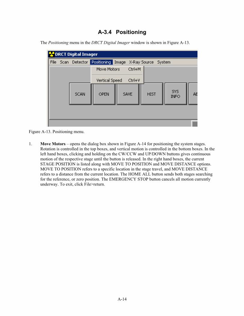
A-14
A-3.4 Positioning
The Positioning menu in the DRCT Digital Imager window is shown in Figure A-13.
Figure A-13. Positioning menu.
1. Move Motors – opens the dialog box shown in Figure A-14 for positioning the system stages. Rotation is controlled in the top boxes, and vertical motion is controlled in the bottom boxes. In the left hand boxes, clicking and holding on the CW/CCW and UP/DOWN buttons gives continuous motion of the respective stage until the button is released. In the right hand boxes, the current STAGE POSITION is listed along with MOVE TO POSITION and MOVE DISTANCE options. MOVE TO POSITION refers to a specific location in the stage travel, and MOVE DISTANCE refers to a distance from the current location. The HOME ALL button sends both stages searching for the reference, or zero position. The EMERGENCY STOP button cancels all motion currently underway. To exit, click File>return.
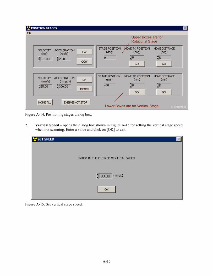
A-15
Figure A-14. Positioning stages dialog box.
2. Vertical Speed – opens the dialog box shown in Figure A-15 for setting the vertical stage speed when not scanning. Enter a value and click on [OK] to exit.
Figure A-15. Set vertical stage speed.

A-16
A-3.5 Image
The Image menu in the DRCT Digital Imager window is shown in Figure A-16.
Figure A-16. Image menu.
1. Histogram – opens a histogram (plot of number of pixels as a function of grey level) for the current image.
2. Rotate – rotates the current image in increments of 90°.
3. Flip – inverts the current image vertically.
4. Line Profile – gives a grey level plot along a line drawn in the current image.
5. Clear Image Window – erases the current image.

A-17
A-3.6 X-Ray Source
The X-Ray Source menu in the DRCT Digital Imager window is shown in Figure A-17.
Figure A-17. X-Ray Source menu.
1. Operate X-Ray Source – opens the virtual x-ray controller shown in Figure A-18. All of the functions available here look and act very much the same as they do on the real x-ray controller, with the chief difference being the absence of a numeric keypad. The long boxes on the left are message windows that give the current status of the x-ray generator. The round, off-safe-on switch mimics the real controller key switch. Simply click on the key position desired. The timer switch toggles the countdown timer on and off. The default position is off, because when countdown reaches zero, the x-ray generator shuts down even if a scan operation is not finished. The desired generator kV and mA are entered at the lower right either by typing in a value or clicking the radio buttons. The radio buttons are useful for incremental kV and mA adjustments during operation. The GREEN button starts x-rays, and the RED button shut them down.
NOTE: The virtual x-ray controller is not a substitute for the real controller. Rather, the virtual controller controls the real controller. It is good practice when using the virtual controller to monitor the actual controller to ensure that it is operating properly. It is especially important to check the actual controller when shutting off x-rays, remove the actual key, and use a survey meter when approaching the x-ray generator.
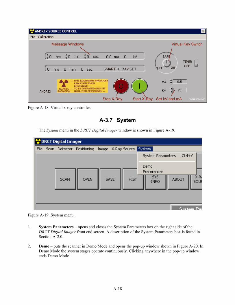
A-18
Figure A-18. Virtual x-ray controller.
A-3.7 System
The System menu in the DRCT Digital Imager window is shown in Figure A-19.
Figure A-19. System menu.
1. System Parameters – opens and closes the System Parameters box on the right side of the DRCT Digital Imager front end screen. A description of the System Parameters box is found in Section A-2.0.
2. Demo – puts the scanner in Demo Mode and opens the pop-up window shown in Figure A-20. In Demo Mode the system stages operate continuously. Clicking anywhere in the pop-up window ends Demo Mode.

A-19
Figure A-20. Demo mode quit button.
3. Preferences – opens Edit Preferences dialog box shown in Figure A-21 where a few preferences can be set and some system parameters are listed.
Figure A-21. Preferences dialog box.
a. Detector Parameters – sets the detector readout rate, or frequency, and the detection integration time. The following three choices are available:
(1) 40 Hz, 20 mSec is the default setting, which will be used for most scan jobs
(2) 60 Hz, 13 mSec should be used for very low density or short path length objects

A-20
(3) 10 Hz, 80 mSec should be used for very high density or long path length objects.
This can also be done from the menu bar by clicking Detector>Detector Setup.
b. Rotate Positioning Speed – rate that the rotation stage turns when not scanning. This is a fixed parameter.
c. Vertical Positioning Speed – rate that the vertical stage moves when not scanning. This parameter is set from the Positioning>Vertical Speed command as described in section A-3.4.2.
d. Lines/mm – number of data lines per millimeter in a RADIOGRAPH data set. This number is calculated by the system computer when setting up a RADIOGRAPH scan.
e. Projections/rev – number of data projections per revolution in a CT scan data set. This number is calculated by the system computer when setting up a CT scan.
f. PITCH (mm/rev) – vertical motion per revolution in a VOLUMETRIC CT data set. This number is calculated by the system computer when setting up a VOLUMETRIC CT scan.
g. Real Time Scope – toggles on and off the virtual oscilloscope that is visible when collecting data. The default setting is off because the oscilloscope slows down the computer processing enough during CT scans to cause data collection problems.
h. Image Display Spectrum – toggles between grey and color scales.
i. Kernel Directory – sets the kernel directory. The kernel directory should never be changed by the operator unless directed to by INL personnel.
A-4. Buttons
With the exception of the [ABOUT] and [http://] buttons, the square buttons are simply quick ways to get to frequently used commands already available in the menu bar.
1. SCAN – initiates the scan process. The operator will be led through a Positioning Setup, an x-ray warning window, and to the virtual x-ray controller where the actual scan is started. Prior to scanning, the desired scan type must be set in the System Parameters box. A description of the scan process is found in Section A-3.2.1.
2. OPEN – opens image files that have been saved in TIFF, JPEG, or BIF file formats. The DRCT Digital Imager will not open files saved with the .ltif file extension in which it saves files.
3. SAVE – saves the current image file with an .ltif file extension. The DRCT Image Processing Interface software is used to open and process these files.
4. HIST – opens a histogram (plot of number of pixels as a function of grey level) for the current image.

A-21
5. SYS INFO – opens and closes the System Parameters box on the right side of the DRCT Digital Imager front-end screen. A description of the System Parameters box is found in Section A-2.0.
6. ABOUT – opens the advertisement window that lists the software producer and version number (see Figure A-22).
Figure A-22. About button.

A-22
7. X-RAY SOURCE – opens the virtual x-ray controller, as described in Section A-3.6.1 and shown in Figure A-18.
8. http:// – allows connection to the DRCT Scanner through the World Wide Web to give troubleshooting access to INL personnel. The electrical box computer must be connected to an outside network.

B-1
Appendix B
DRCT Image Processing Interface

B-2

B-3
Appendix B
DRCT Image Processing Interface This appendix is meant to be a refresher for persons using the imaging-processing graphical user
interface (GUI). The best way to learn about this program is to read in an image and experiment. Images that are read in by the program remain on disk, so the only danger associated with using this interface is the possibility of overwriting good data when an image is saved. This program is fairly robust but still crashes occasionally. Feel free to read in a few images and experiment in order to get used to the features of the interface.
This guide provides a brief introduction to the features of the image-processing interface. A more complete description of the interface can be found in DRCT Image Processing Interface Standalone Manual. This manual is in PDF format on the C: drive of the computer and can be accessed through the drop-down list underneath the Help menu item.
B-1 THE MAIN GUI
The image processing interface is launched by clicking on the desktop icon labeled ImageProcessing Interface (see Figure B-1).
Figure B-1. DRCT Image Processing Interface desktop icon.
Clicking on the icon will launch the image-processing interface. The initial dialog box of the image-processing interface is shown in Figure B-2.
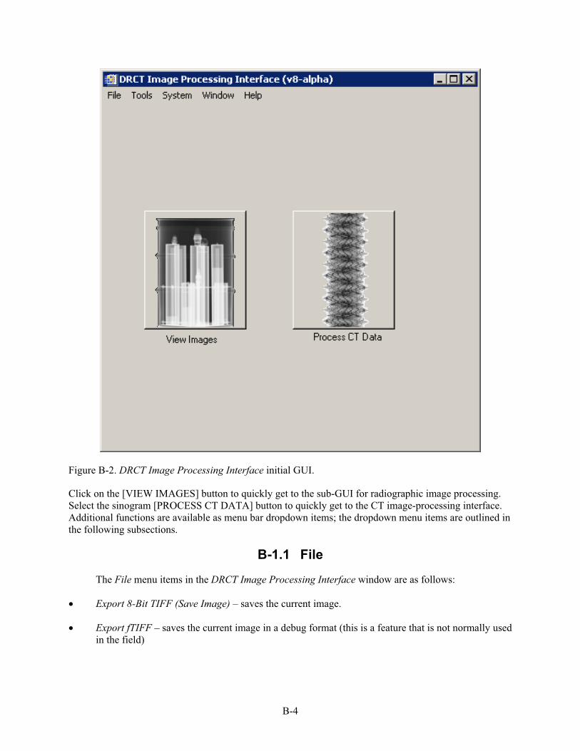
B-4
Figure B-2. DRCT Image Processing Interface initial GUI.
Click on the [VIEW IMAGES] button to quickly get to the sub-GUI for radiographic image processing. Select the sinogram [PROCESS CT DATA] button to quickly get to the CT image-processing interface. Additional functions are available as menu bar dropdown items; the dropdown menu items are outlined in the following subsections.
B-1.1 File
The File menu items in the DRCT Image Processing Interface window are as follows:
Export 8-Bit TIFF (Save Image) – saves the current image.
Export fTIFF – saves the current image in a debug format (this is a feature that is not normally used in the field)

B-5
Print Image – prints the current image (if the system is networked to a system with a printer present or a printer is attached to the parallel port on the gantry).
Quit – exits the interface (all images not saved and will be lost).
B-1.2 Tools
The Tools menu items in the DRCT Image Processing Interface window are as follows:
Select CT Level Single Slice – this option allows the operator to determine the vertical position in a radiograph at which a CT-slice measurement can be taken. When the mouse is moved over this image, a horizontal line is drawn on the current image, and the distance of the line from the bottom of the image is displayed in units of mm. This line can be moved by moving the mouse up and down over the image. When the left mouse button is clicked, a text box appears that informs the user of the height of the line (in mm) from the bottom of the image. This position can be used in the data-collection interface to set the vertical position of a CT data collection.
Process CT Data – opens the CT data-processing sub-GUI (same as pressing the Process CT Databutton on startup).
View Images – opens the radiographic-image-processing sub-GUI (same as pressing the ViewImages button on startup).
Calculate CT Parameters – opens a sub-GUI that is used to calculate CT alignment parameters.
View Reconstructions – opens a sub-GUI that is used to view multiple slices from a 3D CT data collection.
Evaluate Light/Dark File – displays a light or dark image and plots the intra-pixel averages and standard deviations across the detector. This tool is useful for checking calibration images and replaces an older, independent program.
B-1.3 System
The System menu items in the DRCT Image Processing Interface window are as follows:
Detector Type – used to change the type of detector used in the system (for instance, to use the software on the Portable Drum Scanner instead of the Single Munitions Scanner. Typically, this function is used by INL personnel only.
Set Default Parameters – used to write out the default CT-alignment parameters to a text file so that the parameters will be the new default values.
Set Source to Object Distance – used to write out the default distance from the x-ray generator to the object.

B-6
B-1.4 Window
This is a variable-length dropdown menu that allows the user to select the current image. The current image can also be selected by clicking anywhere in an open image or opening a minimized image in the task bar.
B-1.5 Help
The Help menu items in the DRCT Image Processing Interface window are as follows:
DRCT System Manual – launches Adobe Reader and displays the Digital Radiography Computed Tomography User Manual (this manual).
Image-Processing GUI Manual – launches Adobe Reader and displays the Operating Manual for the DRCT Image-Processing Interface.
Detector Gain Settings – launches Adobe Reader and displays a page with the gain settings to be used with the current system.
B-2 THE RADIOGRAPHY SUB-GUI
Select the [BEGIN] button to read in and display a radiograph (see Figure B-3). If light and dark correction from light and dark images is desired (and correction files are available) then first check the boxes next to Dark File Name and/or Light File Name. After the image is displayed, the gray level display can be set by a variety of means in the Gray Level Mapping region of the interface. A variety of image evaluation tools are available in the Image Operations region of the GUI.

B-7
Figure B-3. DRCT Image Processing Interface screen. The Grey Level Mapping (blue circle) functions are found in the lower right region of the interface, and the Image Operations (red circle) functions are found in the lower-left region of the interface.
NOTE: Some image operations, such as Set Gray Level, require the positioning and resizing of a box region. The box can be moved by clicking and dragging with the left mouse button. The box is resized by holding down the control key while simultaneously clicking and dragging with the left button. When the final box position is realized, the region can be selected by clicking with the right mouse button somewhere in the image. While the box is shown on any image on the screen, no other imaging operations can be performed.
B-3 THE CT PROCESSING SUB-GUI
This interface appears similar to the radiography sub-GUI, with the addition of a text box for the name of the reconstruction file. Begin the process by clicking on the [BEGIN RECONSTRUCTION] button. The program will ask for a sinogram filename; this is the name of the file that was saved from the data-collection interface when CT data were collected. Dark and light correction files can be used for image correction by selecting the appropriate boxes (as was done in the radiography sub-GUI). The alignment numbers at the bottom of the screen should be set before beginning the reconstruction. The Reverse Data check box should usually be checked (see Figure B-4).

B-8
Figure B-4. CT reconstruction file input window.
After an initial reconstruction, a higher resolution reconstruction of a smaller region can be performed by clicking the [BEGIN FINE-GRID RECONSTRUCTION] button. Note that the current image must be a CT slice before this button is selected. After clicking on this button, the user will need to use the box-cursor program to select a region of interest for the reconstruction.
B-4 THE CT ALIGNMENT SUB-GUI
This GUI is used with alignment CT data to calibrate the imaging system alignment. This process is necessary if circular artifacts appear in the reconstructed images. Clicking on [OPEN] starts the process. Light and dark files can be used for correction if the appropriate boxes are checked (see Figure B-5).
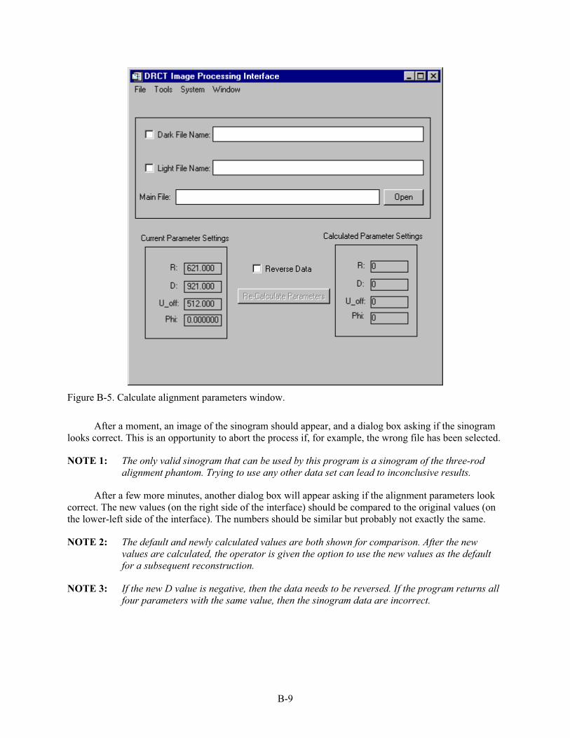
B-9
Figure B-5. Calculate alignment parameters window.
After a moment, an image of the sinogram should appear, and a dialog box asking if the sinogram looks correct. This is an opportunity to abort the process if, for example, the wrong file has been selected.
NOTE 1: The only valid sinogram that can be used by this program is a sinogram of the three-rod alignment phantom. Trying to use any other data set can lead to inconclusive results.
After a few more minutes, another dialog box will appear asking if the alignment parameters look correct. The new values (on the right side of the interface) should be compared to the original values (on the lower-left side of the interface). The numbers should be similar but probably not exactly the same.
NOTE 2: The default and newly calculated values are both shown for comparison. After the new values are calculated, the operator is given the option to use the new values as the default for a subsequent reconstruction.
NOTE 3: If the new D value is negative, then the data needs to be reversed. If the program returns all four parameters with the same value, then the sinogram data are incorrect.

B-10
B-5 EVALUATE LIGHT/DARK FILE
The program for examining a light or dark file can be started by selecting Evaluate Light/Dark Fileunder the Tools option in the menu bar (see Figure B-6).
Figure B-6. Tools dropdown menu.
Selecting this option by clicking on the text Evaluate Light/Dark File with the left mouse button will bring up a browser that can be used to select the dark or light image. After an image is selected, the light or dark file is displayed as an image, and plots of the average pixel intensity and standard-deviation of pixel intensities are shown in separate plot boxes. The average value for a light image should be in the range of 3850 to 4000 and the standard deviation should be in the range of approximately 40. The average value for a dark calibration image should be in the range 18 to 40 and the standard deviation below five. For both calibration images the standard-deviation plot should never drop to zero. Examples of good light and dark images are included in the example-images directory.

C-1
Appendix C
Cheat Sheet to DRCT System Use

C-2

C-3
Appendix C
Cheat Sheet to DRCT System Use
C-1 SYSTEM SETUP
1. Install wheels on gantry, fold out extensions and clamp them down, and set angle bars for tilt position if required.
2. If needed, install rotation stage on gantry and connect motor power. Motor on stage should point toward carriage.
3. If rotate stage is not needed, connect rotate motor bypass module to motor power cable.
4. Install detector on gantry.
5. Install x-ray generator cradle on gantry.
6. Install x-ray generator on x-ray generator cradle.
7. Connect motor cable between electrical box (J1 Control Cable) and gantry.
8. Connect detector cable between electrical box and detector on gantry (three connectors each end: detector communications, detector power, and detector PCI).
9. Connect network cable between LAN ports on network hub and electrical box.
10. Connect network cable between LAN ports on network hub and laptop.
11. Connect x-ray communication cable between electrical box and x-ray control console.
12. Connect controller cable between x-ray generator and x-ray control console.
13. Connect remote safety cable(s) between x-ray control console, electrical box, and remote safety boxes.
14. Connect ground wire from x-ray control console to suitable ground.
15. Connect yellow power cable between x-ray control console and 120V AC outlet.
16. Hang detector and x-ray cables from gantry handle. Ensure that x-ray generator and detector have no obstructions in their travel range and that there is sufficient slack in the cables to translate up and down.
17. Connect electrical box to 120V AC outlet.
18. Turn on computer in electrical box. Power switch is inside door on back of electrical box.
19. Connect hub power supply between network hub and 120V AC outlet.

C-4
20. Wait 2-3 minutes for Electrical Box PC to establish communication with hub.
21. Turn on power to laptop.
22. Ensure all scram buttons and emergency shutoffs are disabled (mushroom switches pulled up).
23. Ensure it is safe to operate x-rays. With solid lead plug in x-ray port, warm up x-ray generator.
24. When warm-up is complete and x-rays are off, switch from the solid plug to the slotted plug on the tube-head.
C-2 DIGITAL RADIOGRAPHY
1. From the laptop computer, double click on [CONNECT TO GANTRY.RDP] icon on desktop to establish communication with electrical box computer. This should display the DRCT Digital Imager and DRCT Image Processing Interface programs that are running on the electrical box computer.
2. From the DRCT Digital Imager, home the motors. If the vertical motor is at the upper limit switch, it does not home.
3. Set the detector readout rate as necessary for the object to be scanned.
4. With x-rays off, set the offset.
5. With x-rays on, set the gain. Gain settings that work for the three choices of readout rates are:
Readout Rate kV mA
60 Hz, 13 mSec 260 2.5
40 Hz, 20 mSec 200 2.7
10 Hz, 80 mSec 175 0.9
6. Collect dark (without x-rays) and light (with x-rays) images and save to proper work folder.
7. Confirm the dark and light images are acceptable. Compare them to the reference dark and light images located in the Reference Files folder using the Evaluate Light and Dark drop down tool in the DRCT Image Processing Interface.
8. Securely install object on rotate stage.
9. Collect digital radiograph of object and save image to proper work folder.
10. Process image with DRCT Image Processing Interface and confirm good image.
You should now have a corrected digital radiograph of the object.

C-5
C-2 COMPUTED TOMOGRAPHY
Upon successful acquisition of a digital radiograph, perform the following steps:
1. From the Tools tab in the DRCT Image Processing Interface, pick CT Level, and choose a desired place on the digital radiograph to collect CT data. This is the height from the bottom of the image.
2. From the DRCT Digital Imager, System Parameters box, change the scan type to CT Slice.
3. Scan at the CT Level determined in Step 1 and save the sinogram to the proper work folder.
4. Perform CT system calibration:
a. Remove the object from the rotate stage and securely install the CT Calibration Phantom.
b. From the DRCT Digital Imager, System Parameters box, change the scan type to Calibrate CT.
c. Scan at the same CT Level used on the object and save the calibration sinogram to proper work folder.
d. From the Tools tab in the DRCT Image Processing Interface, pick Calculate Alignment Parameters and check the boxes for dark and light corrections.
e. Click on Open, select the calibration sinogram, dark, and light files requested in the title bars of the pop-up windows and choose Yes to calculate the alignment parameters.
f. Compare the old and new alignment parameters to ensure reasonable agreement.
5. From the Tools tab in the DRCT Image Processing Interface, pick Process CT Data.
6. Click Begin Reconstruction, select the sinogram, dark, and light files requested in the title bars of the pop-up windows, and choose a valid file name for the reconstructed CT slice.
You should now have a CT image of the object at the scan height.
For a finer reconstruction of a smaller part of the CT image, perform the following steps:
1. Select Process CT Data from the Tools tab in the DRCT Image Processing Interface.
2. Ensure that the current image is the most recent CT reconstruction and click on the [BEGIN FINE GRID RECONSTRUCTION] button.
3. Use the mouse to set desired region of the coarse CT image (left button moves box, middle button stretches box, right button closes box).
4. Choose a valid filename for the fine grid reconstruction.
You should now have a CT image of the object in the smaller region of interest.

C-6
C-3 SYSTEM SHUTDOWN
1. Close the DRCT Image Processing Interface.
2. Close the DRCT Digital Imager. If the system is to be packed up, answer yes to send motors to shutdown position.
3. Shutdown DRCT Scanner computer using the icon on the desktop.
4. Shutdown laptop computer.
5. Unplug and wind up all power cords and cables.
6. Pack components away in appropriate shipping boxes per the inventory checklist (see Appendix E).

D-1
Appendix D
Known System Errors and Troubleshooting

D-2

D-3
Appendix D
Known System Errors and Troubleshooting This appendix contains a list of common problems encountered when using the DRCT system. The
list is in no particular order and will be expanded as the system is used and other errors appear. This list is also not exhaustive.
Because this is a one-of-a-kind system, it is expected that more errors or bugs will be encountered as the system is operated. It would be beneficial to both the system designers and to the operators if the encountered errors were reported promptly to the following developers of the DRCT System:
Don Verrill 208-526-2286 [email protected]
Tim Roney 208-526-9712 timothy.roney.inl.gov
Tim White 208-526-8006 [email protected]
Mike Smith 208-681-0749 [email protected]
In addition, any type of feedback regarding the operational functions of the system, or features to make the system more useful would be appreciated.
D-1 MOTORS DO NOT MOVE
There are many reasons that the motors may not be operable. The first place to check would be to see if the emergency-off switch on the top of the scanner is depressed. If the emergency-off switch appears to be in the up (or on) position, verify this by pressing down on the switch until it clicks into the off position and then twisting to turn it on again. If the motors still do not work, check to see if the fan on the back of the DRCT electrical box appears to be operating. If the fan is off, chances are that the electrical box does not have power. Find an outlet that appears to work and plug the DRCT electrical box into that outlet. If this is not the same power source that is used for the PC and the remote workstation, other parts of the system may need to be plugged into other outlets as well to avoid ground loops.
D-2 THE X-RAY GENERATOR POWER FLUCTUATES WILDLY
If the power to the x-ray system cannot deliver enough energy to the x-ray generator, the x-ray controller may be behaving erratically; the LCD display on the x-ray controller may fluctuate rapidly. This problem may be due to too many components plugged into the same circuit as the x-ray controller, or it could be caused by using an extension cord that does not have the power capacity for the x-ray system. Try using a different circuit for the x-ray system and a thicker extension cord.
D-3 BAD IMAGES
There are many causes and types of bad images. In the section below, some examples of bad images are shown and the cause and/or corrective actions are discussed.

D-4
D-3.1 X-Ray Generator Shut-Off Part Way Through Data Collection
Figure D-1 (see next page) is an example of a data acquisition in which the x-ray generator was inadvertently shut off during data acquisition. A characteristic of this problem is for a region of the image to look underexposed, as if a sheet of lead is blocking the detector. The generator could have been turned off manually at the controller or remote safety, or the timer in the controller could have counted down to zero. The latter case may occur if the generator has had to warm up for a few minutes and then is left in a mode in which it counts down from a preset time instead of counting up. To correct this problem, push the Time button on the controller keypad, enter a time of 00:00 minutes, and push the Enter key. The controller will now count up instead of down.
D-3.2 Bright Vertical Stripes, Low Image Contrast
Figure D-2 is an example of an image that was collected with an improperly calibrated detector. The error could be due to a bad offset/gain calibration. The first corrective action would be to redo the offset and gain to ensure that the x-ray generator voltage and current settings are correct, and then collect another radiograph. If this does not solve the problem, then try shutting off power to the electrical box, waiting a few moments, and restoring power to reset the system. Detector calibration, as outlined in Section 3.5 will have to be redone after power is restored to the system.
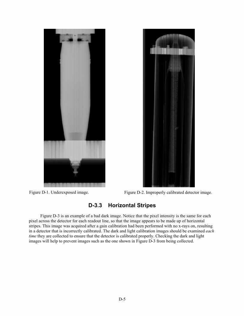
D-5
Figure D-1. Underexposed image. Figure D-2. Improperly calibrated detector image.
D-3.3 Horizontal Stripes
Figure D-3 is an example of a bad dark image. Notice that the pixel intensity is the same for each pixel across the detector for each readout line, so that the image appears to be made up of horizontal stripes. This image was acquired after a gain calibration had been performed with no x-rays on, resulting in a detector that is incorrectly calibrated. The dark and light calibration images should be examined eachtime they are collected to ensure that the detector is calibrated properly. Checking the dark and light images will help to prevent images such as the one shown in Figure D-3 from being collected.

D-6
Figure D-3. Example of a bad dark image.
D-4 THREE-ROD ALIGNMENT PHANTOM DATA
Figure D-4 demonstrates a good (top) and a poor (bottom) sinogram of the three-rod calibration phantom. Notice in the bottom image that the outer wall of the calibration phantom tube can be clearly seen, while the edge of the wall is barely seen in the top image. The bottom image is corrupted because the jaws of the chuck were not centered when this data was collected. The data in the bottom image will confuse and cause the CT alignment program to crash. The chuck jaws should be checked periodically to ensure that the chuck is aligned properly.
Figure D-4. The top figure is an example of a good sinogram of the three-rod object, and the bottom figure is an example of a poor sinogram because the tube walls are visible.

D-7
Figure D-5 shows a calibration sinogram in which there were too many rotations of the rotate stage. This was caused by having the real-time oscilloscope in the DRCT Digital Imager turned on. The calibration sinogram and any object sinogram that were acquired with the real-time oscilloscope turned on need to be reacquired after the real-time oscilloscope is turned off.
Figure D-5. Example of a calibration sinogram in which the calibration phantom was rotated slightly more than two revolutions.
D-5 CT RECONSTRUCTION ERRORS
Figure D-6 demonstrates a good CT reconstruction of the three-rod object. The cross sections of the rods are uniform, round disks.

D-8
Figure D-6. Example demonstrates a good reconstruction of the three-rod object.
Figure D-7 indicates a bad reconstruction of the three-rod object. Notice how the cross-sections of the rods are reconstructed to circles. This artifact is an indication that incorrect alignment parameters have been used for the reconstruction.
Figure D-7. Indicates a bad reconstruction of the three-rod object.
Figure D-8 demonstrates another bad reconstruction. The cross sections of the rods have reconstructed as small stars. This artifact indicates that the Reverse Data checkbox should be either checked or unchecked (should be the opposite of what was used to create this image).
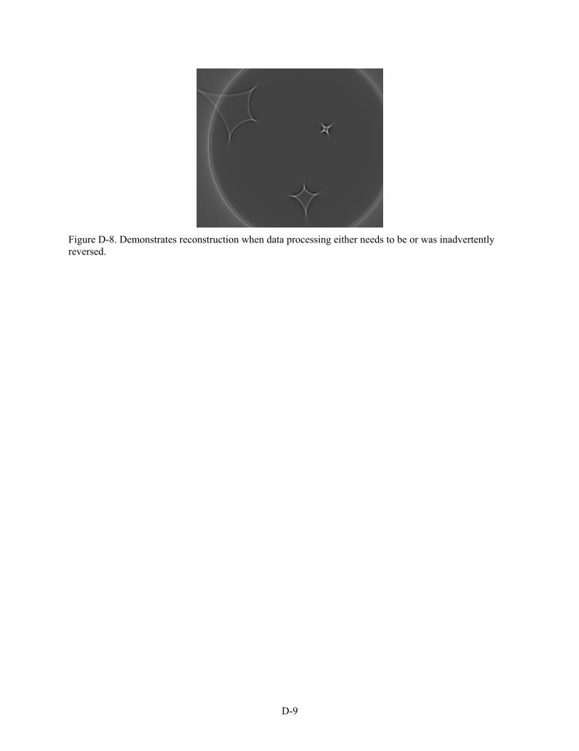
D-9
Figure D-8. Demonstrates reconstruction when data processing either needs to be or was inadvertently reversed.

D-10

E-1
Appendix E
DRCT Inventory Checklist

E-2

E-3
Sample DRCT Inventory Checklist (individual model inventories may vary slightly)
Gantry Box ____ gantry ____ 2 wheels ____ 2 thumbscrews ____ 4 flat washers ____ electronics box containing CPU
X-Ray Generator Box ____ x-ray generator (tubehead), Yxlon Model: SMART 300 HD Serial No. __________
X-Ray CT Controller Box ____ x-ray control console
Yxlon Model: SMART 583 Serial No. __________ ____ console key ____ gray accessories bag
____ 50 ft yellow power cable ____ green/yellow ground cable ____ 3 meter remote safety cable ____ 15–70 meter remote safety cable ____ x-ray communication cable ____ network cable (Cat. 5) ____ network hub and power supply ____ electrical box power cord ____ spare fuses/lamp package (recommend 5 fuses ea. and 2 bulbs ea.)
____ 2 Amp fuse (F2L250V) ____ 10 Amp fuse (F10/250E) ____ 20 Amp fuse (F20/250V) ____ SMART 300 bulb (JAN24V3W9021) ____ SMART 583 bulb (12V100mA) ____ spare console key
____ 12 mm solid lead plug ____ 12 mm slotted lead plug with 2 copper filters (1 mm ea.) ____ small flat head screwdriver (for connecting cable ends)
____ radiation survey meters (2) Make_______________ Model____________________ Serial Nos._____________ Calibrations_______________

E-4
Detector Box ____ detector assembly containing LDA, Thales Model: TH 9599 400 Serial No._______________
Rotation Stage Box ____ rotation stage assembly ____ accessory jaws box (one set of jaws will probably be on the rotation stage)
____ 3 steel jaws ____ 3 plastic jaws ____ 3 long extension jaws ____ allen wrench
____ standard chuck key and/or speed wrench chuck key ____ tubehead cradle
Remote Computer Bag ____ laptop computer Make/Model_______________ Serial No._______________ ____ USB mouse ____ power supply and cord
Loose Items ____ Remote Safety Box #1 (includes key) ____ Remote Safety Box #2 (includes key and shorting plug) ____ Cable Reel #1 (controller/safety circuit cable) ____ Cable Reel #2 (red Cat. 5 network cable) ____ Cable Reel #3 (motor control cable) ____ Cable Reel #4 (detector cable assembly) ____ CT calibration phantom