Portable Data Acquisition System (PDAS) User Manual
19
Bolder Flight Systems PDAS User Manual 1 | Page Portable Data Acquisition System (PDAS) User Manual Firmware v1.2.3 Document Revision 1.5
Transcript of Portable Data Acquisition System (PDAS) User Manual

Bolder Flight Systems PDAS User Manual
1 | P a g e
Portable Data Acquisition System (PDAS)
User Manual
Firmware v1.2.3
Document Revision 1.5

Bolder Flight Systems PDAS User Manual
2 | P a g e
Table of Contents 1 Technical Documentation ......................................................................................................................................... 3 2 Introduction ............................................................................................................................................................. 3
2.1 Description ....................................................................................................................................................... 3 2.2 Measurement Outputs ..................................................................................................................................... 3 2.3 System Modules ............................................................................................................................................... 4
2.3.1 Configuration ............................................................................................................................................ 5 2.3.2 INS ............................................................................................................................................................ 5 2.3.3 Air Data..................................................................................................................................................... 5 2.3.4 Analog ...................................................................................................................................................... 6 2.3.5 FTE Interface ............................................................................................................................................. 6 2.3.6 IADS .......................................................................................................................................................... 6 2.3.7 Datalog ..................................................................................................................................................... 6
2.4 System States ................................................................................................................................................... 6 3 Specifications ........................................................................................................................................................... 7
3.1 Electrical ........................................................................................................................................................... 7 3.1.1 Power ....................................................................................................................................................... 7 3.1.2 FTE Interface ............................................................................................................................................. 7 3.1.3 GNSS Antenna ........................................................................................................................................... 7 3.1.4 External Sensors........................................................................................................................................ 7
3.2 Dimensions ....................................................................................................................................................... 8 3.3 Sensing ............................................................................................................................................................. 9 3.4 Maximum Ratings ............................................................................................................................................. 9 3.5 Coordinate System ..........................................................................................................................................10
4 Operations ..............................................................................................................................................................10 4.1 Overview .........................................................................................................................................................10 4.2 Interfaces ........................................................................................................................................................11
4.2.1 Power Input .............................................................................................................................................11 4.2.2 State Switch and Status Indicators ...........................................................................................................11 4.2.3 FTE Interface ............................................................................................................................................12 4.2.4 External Sensors.......................................................................................................................................13 4.2.5 GNSS Antenna ..........................................................................................................................................13 4.2.6 Pitot-Static ...............................................................................................................................................13
4.3 Configuration...................................................................................................................................................13 4.3.1 Device Information ..................................................................................................................................14 4.3.2 INS ...........................................................................................................................................................15 4.3.3 Air Data....................................................................................................................................................15 4.3.4 Analog .....................................................................................................................................................16 4.3.5 Data Files .................................................................................................................................................16
4.4 IADS.................................................................................................................................................................16 4.5 Data Conversion ..............................................................................................................................................16
5 Appendix A – Data File Description ..........................................................................................................................17 6 Appendix B – Acronyms ...........................................................................................................................................19

Bolder Flight Systems PDAS User Manual
3 | P a g e
1 Technical Documentation The following documentation and support software are available from our website, https://bolderflight.com/pdas:
• PDAS User Manual: describes the PDAS, specifications, operations, and data.
• PDAS Data Converter: a stand-alone executable for the Windows operating system. This software converts
PDAS generated data files to CSV or MATLAB mat formats.
• PDAS PRN file: a file specifying the data packet sent by the PDAS to an IADS client. Used by the Symvionics IADS
software to setup the PDAS as a data source for building real-time displays and analysis tools.
If you have technical problems or cannot find the information you need in the provided documents, please contact our
technical support team by email at: [email protected]. Our team is committed to providing the support
necessary to ensure that you are successful with the integration and operations of our data acquisition system.
2 Introduction
2.1 Description The Portable Data Acquisition System (PDAS) is a portable, high-performance data acquisition system for aeronautics
research. It is designed to quickly and easily integrate on a fixed or rotary wing aircraft and provide high quality flight
data to support analysis of vehicle performance, dynamics, and control. PDAS consists of:
• A high-accuracy GNSS-aided Inertial Navigation System (INS), providing high-rate estimates of inertial position,
attitude angles, linear and angular rates, linear accelerations, and uncertainty estimates.
• Pitot-static pressure transducers measuring differential and static pressures, altitudes, and airspeeds.
• A Resistive Temperature Device (RTD) analog front-end for supporting high-accuracy Outside Air Temperature
(OAT) measurement.
• 12 analog channels with 16-bit resolution. Each channel features: an analog front end with integrated anti-alias
filtering, a configurable amplifier, and an independent, ultra-low noise +5V supply for powering analog sensors.
Six channels have configurable gains of 1, 2, 4, or 8 while the other six channels have configurable gains of 1, 10,
100, or 1000. Each channel can accept differential and single-ended inputs. Ideal for measuring strain bridges
and potentiometers.
• A high-performance, hard real-time processor to sample sensors, apply real-time filtering and estimation
algorithms, and log data to non-volatile memory.
• A hand-held Flight Test Engineer (FTE) interface for setting test point numbers and flagging whether a test point
is actively under test. Extremely useful for correlating flight data to test cards and quickly selecting active test
points for analysis.
• A Symvionics IADS interface for creating real-time displays and analysis tools.
• A convenient web-based interface for configuring the PDAS and managing data files.
• A Windows application for converting binary data logs to CSV or MATLAB mat files.
Data is sampled and recorded at a rate of 200 Hz. PDAS is powered from a USB port and consumes approximately 1 Amp
of current. Included is a 20 Amp-hour battery and a DC/DC converter for optionally powering directly from the aircraft.
2.2 Measurement Outputs Outputs from the PDAS include:
• Time (microsecond resolution)
• Test point number
• Whether the test point was active or inactive

Bolder Flight Systems PDAS User Manual
4 | P a g e
• IMU measurements:
Uncompensated accelerometer, gyro, and magnetometer
• GNSS measurements:
Time of week
GNSS week number
Fix type
Number of satellites
Latitude, longitude, and altitude
North, east, and down velocities
Estimated position and velocity measurement accuracy
• INS estimates:
Accelerometer, gyro, and magnetometer measurements compensated for estimated sensor bias and
low pass filtered
Latitude, longitude, and altitude
North, east, and down velocities
Pitch and roll angles
Yaw relative to true north
Estimated attitude, position, and velocity uncertainty
• Air Data Measurements:
Static and differential pressures
Filtered static and differential pressures
Outside air temperature (OAT)
Filtered outside air temperature (OAT)
Indicated airspeed (IAS), equivalent airspeed (EAS), and true airspeed (TAS)
Pressure altitude, altitude above ground level, and density altitude
• Analog measurements:
Measured voltages
Filtered voltages
Calibrated values by evaluating a polynomial at the filtered voltage
2.3 System Modules PDAS consists of seven modules: Configuration, INS, air data, analog, FTE interface, IADS, and datalog.
Configuration
• Load, update,
and save
PDAS config
Air Data
• Sample
pressure
transducers
and RTD
• Filters data
• Estimates
airspeeds and
altitudes
Analog
• Control PGAs
• Sample
analog
channels
• Apply digital
filtering
• Apply
polynomial
coefficients
INS
• Sample IMU
and GNSS
• EKF estimate
inertial states
• Estimates
sensor biases
and scale
factors
• Regulates
system clock

Bolder Flight Systems PDAS User Manual
5 | P a g e
2.3.1 Configuration The configuration module is responsible for loading, updating, and saving the PDAS configuration. Configurable items
include:
• PDAS orientation relative to the vehicle
• GNSS antenna offset
• Digital low pass filter cutoff frequencies for all sensors
• Whether the pitot-static, OAT, and analog channels are enabled
• OAT RTD configuration
• Analog channel calibration coefficients
This module is one of the first modules to run during the PDAS initialization sequence and loads the stored PDAS
configuration from non-volatile memory. A web server is included, which enables the user to: view current PDAS sensor
and estimation data, view the current PDAS configuration, and update the PDAS configuration. Configuration updates
take effect immediately and are validated and saved to non-volatile memory.
2.3.2 INS The INS module communicates with an inertial measurement unit (IMU) and a GNSS receiver in order to estimate the
vehicle’s inertial states in real-time. An Extended Kalman Filter (EKF) is used to estimate these states with the IMU
providing data for the EKF time update and the GNSS data used as an EKF measurement update. This process leads to
highly-accurate estimates of the vehicle inertial states; however, it requires GNSS lock and adequate vehicle motion. The
estimated states include: vehicle attitude, heading, position, three-dimensional velocity, angular rate, linear
acceleration, and sensor bias and scale factor estimates. In addition to the estimated and filtered states, the INS module
provides the raw IMU and GNSS data.
The PDAS data collection loop is slaved to the INS module data ready interrupt. This ensures that updated INS data is
available every frame and synchronizes all of the PDAS sensors, which provides more accurate data analysis by
minimizing time skew between sensor measurements.
2.3.3 Air Data The air data module samples pressure transducers to measure static and differential pressure. Several pressure
transducers are used to minimize error while maintaining a large overall range. An analog front end for RTD sensors is
FTE Interface
• Displays test
point number
• Sets active /
inactive test
point
Datalog
• Configures
non-volatile
memory
• Compresses,
buffers, and
records data
at the system
rate of 200 Hz
IADS
• Configures
IADS data
sources
• Sends data to
IADS Real
Time Client at
50 Hz
Figure 1: PDAS software modules.

Bolder Flight Systems PDAS User Manual
6 | P a g e
included for high-accuracy Outside Air Temperature (OAT) measurement. This front end supports 2-wire, 3-wire, and 4-
wire sensors with 0 oC resistance values from 10 Ohms to 1000 Ohms and a selection of excitation currents. The module
uses these measurements to estimates Indicated Airspeed (IAS), Equivalent Airspeed (EAS), True Airspeed (TAS),
pressure altitude, Above Ground Level (AGL) altitude, and density altitude. Estimation of TAS and density altitude
require the OAT sensor to be present and properly configured. AGL altitude is estimated with respect to the altitude
when the PDAS static pressure was tared.
2.3.4 Analog The analog module samples analog input data and applies a polynomial calibration to convert measured voltages to
engineering units, such as control surface position, control stick position, or control stick force. Twelve analog channels
are available. Each channel has a programmable gain amplifier, which can be configured for gains of 1, 10, 100, and 1000
on channels 0 - 5. These gain values are ideal for integration with strain bridges. Channels 6 - 11 have configurable gains
of 1, 2, 4, and 8, which are more appropriate for analog position sensors.
An ultra-low noise +5V supply is available on each channel for powering analog sensors. Each channel can accept
differential or single-ended inputs with a voltage range is 0 - 5V. Protection against overvoltage is included. A low-noise
first order anti-alias filter is present on each channel with a cutoff frequency of 55 Hz along with independently
configurable digital low pass filters.
Coefficients can be configured to apply up to a 5th order polynomial to the filtered voltage value for converting voltages
to engineering units.
2.3.5 FTE Interface The Flight Test Engineer (FTE) interface module manages communication with the FTE interface and updates the test
point number and active status.
2.3.6 IADS Symvionics IADS is a real-time test display and analysis suite. Our IADS module acts as a data source and IADS server to
the real time display client. All of the PDAS data is available and transmitted to IADS at a rate of 50 Hz.
2.3.7 Datalog The datalog module logs data to non-volatile memory in real-time. This module uses a compressed binary format
optimized for file size and speed, while preserving data resolution. A converter is available as a stand-alone executable
for the Windows operating system, which converts from this binary format to a CSV file that can be loaded into analysis
software.
2.4 System States The PDAS has three states: initialization, standby, and run.
State Switch Controlled Transition
Automatic Transition
Close log file
Create log file
Init
• Startup processor
• Load config
• Initialize and
configure sensors
• Initialize config
and IADS servers
Standby
• Refresh config and
IADS servers
• Update and save
config changes
• Polls sensor data
Run
• Polls sensor data
• Logs data
• Refresh IADS
server

Bolder Flight Systems PDAS User Manual
7 | P a g e
Upon receiving power, the PDAS automatically transitions through the initialization state and enters the standby state.
In the standby state, all of the software modules are active except for datalog. In this state, you can view PDAS data via
the web server or IADS server, modify the PDAS configuration, and download or delete data log files from the PDAS
storage.
A switch is used to command the PDAS to transition from the standby state to the run state. In the run state, all of the
software modules are active except for the configuration module. Configuration changes are not allowed and the web
interface is disabled while in the run state. IADS is still available to support real-time displays and analysis tools.
Data log files are created each time the PDAS enters the run state. These files are numbered sequentially starting from
data0.pdas with the number incremented to prevent overwriting old log files.
3 Specifications
3.1 Electrical
3.1.1 Power PDAS power is applied to the USB port, please do not attempt to supply power via any other port.
• Voltage input: 3.4 - 6V DC
• Current draw: 1A
A 20 Ah battery is supplied with the PDAS along with a charger and a DC/DC converter. The DC/DC converter is capable
of powering the PDAS from a 9 - 48V source.
3.1.2 FTE Interface The FTE interface is connected via a 9 pin D-Sub (DB9) cable. One of these cables is provided with the PDAS. Please be
cautious if purchasing an after-market cable and ensure that a straight-through cable is used, rather than a crossover
cable. Although a DB9 cable is used for the FTE interface, it is not a serial port, applying RS-232 or TTL voltages to this
port may damage the PDAS or FTE interface. Only use this interface for connecting the PDAS to the FTE interface.
3.1.3 GNSS Antenna The GNSS receiver interfaces with an active antenna via an SMA port, which is capable of suppling 3V and up to 40 mA of
current to the antenna. The uBlox ANN-MS-0 active antenna is supplied with the PDAS, which is available from uBlox and
electronics distributors if you need to replace or purchase additional antennas.
3.1.4 External Sensors Analog and RTD sensors are connected via a 62 pin D-Sub connector. The pinout of this port is below. Limit the voltage
on analog inputs to 0 - 5V and be aware that the ultra-low noise +5V supplies can source 50 mA of current per channel.

Bolder Flight Systems PDAS User Manual
8 | P a g e
Table 1: External sensors pinout.
Pin Description Pin Description Pin Description Pin Description
1 CH 0: 5V Supply 17 CH 7: 5V Supply 33 GND 49 GND
2 CH 0: +Input 18 CH 7: +Input 34 CH 8: 5V Supply 50 GND
3 CH 0: -Input 19 CH 7: -Input 35 CH 8: +Input 51 CH 11: 5V Supply
4 GND 20 GND 36 CH 8: -Input 52 CH 11: +Input
5 CH 1: 5V Supply 21 GND 37 GND 53 CH 11: -Input
6 CH 1: +Input 22 CH 5: 5V Supply 38 CH 9: 5V Supply 54 GND
7 CH 1: -Input 23 CH 5: +Input 39 CH 9: +Input 55 GND
8 GND 24 CH 5: -Input 40 CH 9: -Input 56 GND
9 CH 2: 5V Supply 25 GND 41 GND 57 RTD1
10 CH 2: +Input 26 CH 3: 5V Supply 42 GND 58 RTD2
11 CH 2: -Input 27 CH 3: +Input 43 GND 59 RTD3
12 GND 28 CH 3: -Input 44 GND 60 RTD4
13 CH 6: 5V Supply 29 GND 45 CH 10: 5V Supply 61 GND
14 CH 6: +Input 30 CH 4: 5V Supply 46 CH 10: +Input 62 GND
15 CH 6: -Input 31 CH 4: +Input 47 CH 10: -Input
16 GND 32 CH 4: -Input 48 GND
3.2 Dimensions Dimensions for the PDAS and FTE Interface are below, all dimensions are given in mm.
(a) (b)
Figure 2: PDAS (a) and FTE interface (b) dimensions

Bolder Flight Systems PDAS User Manual
9 | P a g e
3.3 Sensing • 200 Hz data rate
• INS:
Pitch/Roll accuracy: 0.03o
Heading accuracy: 0.3o
Horizontal position accuracy: 8 ft
Vertical position accuracy: 8 ft
Inertial velocity accuracy: 0.1 knots
• Pitot-Static:
Airspeed range: 0 - 340 knots
Airspeed accuracy: 1 knot, typical
• RTD:
Type: 2-wire, 3-wire, and 4-wire
Resistance: PT10, PT50, PT100, PT200, PT500, PT1000
Excitation Current: 5 µA, 10 µA, 25 µA, 50 µA, 100 µA, 250 µA, 500 µA, 1000 µA
Sense Resistor: 2kΩ
0.1 oC accuracy over full temperature range
• Analog:
16-bit resolution
CH 0 - 5: Configurable gain of 1, 10, 100, or 1000
CH 6 - 11: Configurable gain of 1, 2, 4, or 8
Differential and single-ended input available on each channel
Anti-alias filter cutoff frequency: 55 Hz
Ultra-low noise +5V source on each channel
Configurable polynomial coefficients for converting voltage to engineering units
3.4 Maximum Ratings • Acceleration: +/- 16 g
• Rotation: +/- 2,000 deg/s
• Airspeed: 0 to 340 knots
• Altitude: -10,000 to +70,000 ft
• Temperature: -10 to +50C

Bolder Flight Systems PDAS User Manual
10 | P a g e
3.5 Coordinate System The PDAS uses a right-handed coordinate system, Figure 3.
Figure 3: PDAS coordinate system
Where roll is defined as a rotation about the x-axis, pitch a rotation about the y-axis, and yaw a rotation about the z-axis.
Inertial position is given in Latitude, Longitude, Altitude (LLA) format with respect to the WGS84 ellipsoid.
4 Operations
4.1 Overview Typical operation of the PDAS would follow the sequence:
1. Apply power
2. Check PDAS configuration
3. Remove pitot-tube covers and zero the pitot-static system, if applicable
4. Wait for GNSS lock
5. Switch PDAS to the run state
6. Verify that PDAS is in run state with GNSS lock
7. Proceed to flight test operations using IADS displays and the flight test engineer interface as desired
8. Post flight, switch the PDAS to the standby state
9. Use the PDAS web interface to download the data file
10. Use the data file converter executable to convert the data file to CSV format
11. Load the data into your analysis tools and analyze the results
+X
+Y
+Z

Bolder Flight Systems PDAS User Manual
11 | P a g e
4.2 Interfaces Depictions of the PDAS and FTE interfaces is in Figure 4 and Figure 5, respectively. Detailed descriptions of the physical
and software interfaces follow.
Label Description Label Description Label Description
A State switch D Ethernet G Static Pressure
B Status Indicators E FTE Interface H Differential
Pressure
C USB Type B Power
Input F External Sensors I GNSS Antenna
Figure 4: PDAS interfaces overview
Label Description Label Description Label Description A FTE interface C Active Switch E Active Indicator
B Test Point Display D Inactive Indicator
Figure 5: FTE interface overview
4.2.1 Power Input Power is supplied via a USB type B port. The PDAS begins its initialization sequence and transition to the standby state
automatically once power is applied.
4.2.2 State Switch and Status Indicators The state switch commands the PDAS to the run state in the up position and the standby state in the down position. This
switch is a locking-lever type, which requires the level to be pulled out before it is switched. There are four indicator
lights on the PDAS as summarized below.
A
B C
D E
F
G H
I
A
B
C
D
E

Bolder Flight Systems PDAS User Manual
12 | P a g e
Light Position Indication Description
Power Upper Left Off PDAS power is off.
On PDAS power is on.
State Lower Left Off PDAS is in Standby.
On PDAS is in Run.
GNSS Lock Upper Right Off Inadequate GNSS fix.
On 3D GNSS fix.
Fault Lower Right
Off No faults encountered.
Blinking Fault during initialization, check config. More details
provided below.
On Hard fault. Contact Bolder Flight Systems to
troubleshoot.
A blinking fault light indicates that the PDAS encountered faults during initialization. This is typically caused by an RTD
sensor configured, but no longer connected to the PDAS. You should check your PDAS configuration and wiring to
ensure that the configuration is correct for the aircraft setup and that your RTD is properly connected to the PDAS, if you
intend to use one during the flight tests.
A less likely cause of this fault is a corrupted PDAS configuration. The PDAS uses a checksum to protect against
corruption, and in this case the PDAS detected an incorrect checksum and reset the configuration to default values. You
should check and update the PDAS configuration prior to flight.
A hard fault is indicated when the PDAS fails one of its built-in tests during initialization or cannot communicate with one
of its internal sensors. Please contact Bolder Flight Systems’ support team at [email protected] to fix this fault.
PDAS state, GNSS lock, and soft fault status is available within IADS, see Appendix A for parameter names.
4.2.3 FTE Interface The FTE interface has a numeric display, a switch, and two LEDS – one red and one indigo. The numeric display indicates
the test point number. With the switch in the down position, the test point is inactive and the red light is illuminated.
When the switch is moved to the up position, the test point number is incremented and the test point is active, as
indicated by an illuminated indigo light. If the switch is moved down again, the test point is inactivated. This sequence is
shown below; if the switch were moved up again, test point 2 would be selected and active.
Figure 6: Using the FTE interface to set the test point number and active mode
The test point number is always incremented as the switch is moved up to the active position. Our recommendation is to
move the switch from inactive to active a few seconds before the start of a test point maneuver and then note the test
point number in your test cards. A few seconds after the maneuver, move the switch back to inactive. This procedure
will:
• Enable you to quickly correlate test point maneuvers with test cards and notes. You can search the data for the
test point in active mode with the test point number corresponding to the number noted in the test cards.

Bolder Flight Systems PDAS User Manual
13 | P a g e
• Changing the test point active mode a few seconds before and after the maneuver will give you trim data at the
start and completion of the test point. Often this is useful for data analysis.
4.2.4 External Sensors Analog sensors and the RTD are integrated with the PDAS via a 62 pin D-sub connector. The pinout for this connector is
given in Section 3.1.4, Table 1.
4.2.4.1 Analog Input
Channels 0 - 5 have gain value options of 1, 10, 100, and 1000. Channels 6 - 11 have gain value options of 1, 2, 4, and 8.
Each analog supply is capable of providing up to 50 mA of current. If a single-sided input is used, tie the -Input signal to
ground.
4.2.4.2 RTD Input
The wire diagrams below depict the wiring for 2, 3, and 4 wire RTD’s.
Figure 7: RTD wiring
Choose an excitation current such that the maximum voltage drop across the sensor or sense resistor is nominally 1V.
The current selected is the total current flowing through the RTD independent of the wiring configuration. For 3-wire
RTDs the current through the sense resistor is 2x the selected current. A 2kΩ sense resistor is used in PDAS.
4.2.5 GNSS Antenna An active GNSS antenna should be connected to the PDAS using the supplied port via an SMA connector.
3V and up to 40 mA of current are supplied to the antenna. The uBlox ANN-MS-0 active antenna is supplied with the
PDAS and meets these requirements. A GNSS antenna should always be used with the PDAS and a good fix achieved, as
indicated by the green GNSS lock light illuminated, prior to starting flight. Due to the nature of using a GNSS aided INS,
INS accuracy is highly dependent on good GNSS data.
GNSS antenna offset relative to the PDAS is a configurable item.
4.2.6 Pitot-Static Pitot-static pressure ports are available for collecting air data information. Flexible tubing with an Inner Diameter (ID) of
1/8” and a maximum wall thickness of 5/16” should be used for interfacing to these ports. McMaster Carr supplies
tubing, fittings, and reducers to interface with your aircraft pitot-static system.
4.3 Configuration The PDAS is configured using a web-based interface. To access this interface, power the PDAS and ensure you are in the
standby state. Connect an ethernet cable from the PDAS to your computer and manually change your IPv4 address
settings to:
2 W
ire
3 W
ire
4 W
ire
RTD1
RTD2
RTD1
RTD2
RTD3
RTD1
RTD2
RTD3
RTD4

Bolder Flight Systems PDAS User Manual
14 | P a g e
• Address: 192.168.1.1 to 192.168.1.253
• Netmask: 255.255.255.0
• Gateway: 192.168.1.1
Next, open your preferred web browser and navigate to 192.168.1.254 and you should see the following page:
Figure 8: PDAS configuration web page
This page enables to you view real-time data from the PDAS, configure PDAS components, and download and delete
data files. The following sections describe configuration in detail. The current configuration is always displayed in the
fields; after you modify it, be sure to press the Update Config button for the changes to take effect. press the Restore
Defaults button to return to the factory default configuration at any time.
4.3.1 Device Information The PDAS serial number and software version is displayed along with an estimate of the storage space available for data
logging, given in hours.

Bolder Flight Systems PDAS User Manual
15 | P a g e
4.3.2 INS The INS configurable items include the orientation of the PDAS within the vehicle, the offset from the PDAS to the GNSS
antenna, and the digital lowpass filter cutoff frequency.
A rotation matrix is used to transform inertial measurements from the PDAS reference frame, as described in Section 0,
to the vehicle frame. For correct estimation of aircraft attitude angles, the PDAS x-axis should be aligned to point out the
aircraft’s nose and the PDAS y-axis out the right wing. The matrix is defined as:
𝑥𝑦𝑧
𝑎/𝑐
= [𝐶00 𝐶10 𝐶20𝐶01 𝐶11 𝐶21𝐶02 𝐶12 𝐶22
] 𝑥𝑦𝑧
𝑃𝐷𝐴𝑆
The C matrix must be orthonormal and right-handed, with coefficients between -1 and 1. By default this matrix is the
identity matrix.
The GNSS antenna offset defines the antenna position, relative to the PDAS, expressed in the vehicle’s reference frame.
Accelerometer, gyro, and magnetometer measurements are compensated for estimated biases and scale factors. Then a
first order digital low pass filter is applied. This filter is applied after the EKF and does not affect other INS
measurements. The cutoff frequency for this filtering is configurable and the default is 20 Hz.
4.3.3 Air Data Pitot-static measurements and estimates can be enabled or disabled depending on whether the PDAS is integrated with
the aircraft pitot-static system. First order digital low pass filters are applied the measured static and differential
pressures, which are then used to estimate altitudes and airspeeds. The cutoff frequency for this filtering is configurable
and the default is 20 Hz.
Static and differential pressure can be tared using buttons on the PDAS configuration. A tare on the differential pressure
is essential for accurate differential pressure measurement and airspeed estimation. A static pressure tare enables
estimation of the height above the tare location. A tare should be performed just prior to every flight that these
measurements are desired. These systems should be tared with the pitot tube covers removed, the aircraft stationary,
and not pointed into the wind.
OAT measurements and estimates can be enabled or disabled depending on whether an RTD sensor is integrated with
the PDAS. RTD configurable items include the number of wires, 0 oC resistance, and the excitation current. A first order
digital low pass filter is applied to the measured temperature; the cutoff frequency of this filter is configurable and the
default value is 20 Hz.
If pitot-static is enabled, the following measurements will be available:
• Static and differential pressures
• Filtered static and differential pressures
• Pressure altitude
• Indicated airspeed
• Equivalent airspeed
If OAT is enabled, the following measurements will be available:
• OAT
• Filtered OAT

Bolder Flight Systems PDAS User Manual
16 | P a g e
If both the pitot-static and OAT are enabled, the following additional measurements will be available:
• Density altitude
• True airspeed
4.3.4 Analog Each analog channel can be enabled depending on whether analog sensors are integrated with that channel. Amplifier
gain can be selected. Channels 0 - 5 have gains of 1, 10, 100, and 1000 available; Channels 6 - 11 have gains of 1, 2, 4,
and 8. Amplifier gains are not removed in post-processing. For example, if a voltage of 0.1V is measured with a gain of 1,
a voltage of 0.2V will be measured with the gain set to 2.
A first order digital low pass filter is applied to the voltage on each channel. The cutoff frequency of the filter is
configurable and the default value is 20 Hz.
Up to a 5th order polynomial can be defined for each channel to convert the filtered voltage to engineering units, such as
force and displacement values. The polynomial order should be selected and the polynomial coefficients are entered in
order of descending power.
4.3.5 Data Files Data files stored on the PDAS are displayed and can be downloaded or deleted using the buttons provided with each.
4.4 IADS PDAS is setup to run as a Symvionics IADS data source in both the standby and run state. All PDAS data is available and
data is streamed to IADS at 50 Hz. To configure PDAS as an IADS data source, ensure the PDAS is connected to your
computer with an ethernet cable and is powered. Change your IPv4 address settings to:
• Address: 192.168.1.1 to 192.168.1.253
• Netmask: 255.255.255.0
• Gateway: 192.168.1.1
Select the following options while starting IADS:
• Data Source: IADS Custom
• Host Name: 192.168.1.254
• Port ID: 49000
• PRN File: download the prn file that was sent with PDAS and select it
4.5 Data Conversion PDAS stores data in a compressed binary format that is optimized for file size and speed. A standalone Windows
executable was shipped with PDAS to convert these binary files to CSV or MATLAB mat files. Double click the executable
to start the command line program and select the data file to convert and the destination location. A progress bar is
displayed and the program will let you know when it is complete. A list of available data channels, their units, their name
in IADS and MATLAB, and their column number in the CSV file is in Appendix A.

Bolder Flight Systems PDAS User Manual
17 | P a g e
5 Appendix A – Data File Description CSV
Column IADS Name Description Units
1 Time. s
2 active Test point active (1) or inactive (0) flag. 3 test_point Test point number.
4 imu_accel_x_g IMU x-axis accelerometer data. Uncompensated and unfiltered. g
5 imu_accel_y_g IMU y-axis accelerometer data. Uncompensated and unfiltered. g
6 imu_accel_z_g IMU z-axis accelerometer data. Uncompensated and unfiltered. g
7 imu_gyro_x_dps IMU x-axis gyro data. Uncompensated and unfiltered. deg/s
8 imu_gyro_y_dps IMU y-axis gyro data. Uncompensated and unfiltered. deg/s
9 imu_gyro_z_dps IMU z-axis gyro data. Uncompensated and unfiltered. deg/s
10 imu_mag_x_ut IMU x-axis magnetometer data. Uncompensated and unfiltered. µT
11 imu_mag_y_ut IMU y-axis magnetometer data. Uncompensated and unfiltered. µT
12 imu_mag_z_ut IMU z-axis magnetometer data. Uncompensated and unfiltered. µT
13 gnss_tow_s GNSS Time of Week (TOW). s
14 gnss_week GNSS week number. 15 gnss_num_sat Number of satellites used in GNSS Solution.
16 gnss_fix_type GNSS fix (3 = 3D fix, 2 = 2D fix, 1 = time only, 0 = no fix).
17 gnss_lat_deg GNSS latitude. deg
18 gnss_long_deg GNSS longitude. deg 19 gnss_alt_ft GNSS altitude. ft
20 gnss_north_vel_kts GNSS north velocity. kts
21 gnss_east_vel_kts GNSS east velocity. kts
22 gnss_down_vel_kts GNSS down velocity. kts
23 gnss_horiz_acc_ft Estimated GNSS horizontal position accuracy. ft
24 gnss_vert_acc_ft Estimated GNSS vertical position accuracy. ft 25 gnss_speed_acc_kts Estimated GNSS speed accuracy. kts
26 ekf_accel_x_g INS x-axis accelerometer. Compensated from EKF error estimate and filtered. g
27 ekf_accel_y_g INS y-axis accelerometer. Compensated from EKF error estimate and filtered. g
28 ekf_accel_z_g INS z-axis accelerometer. Compensated from EKF error estimate and filtered. g
29 ekf_gyro_x_dps INS x-axis gyro. Compensated from EKF error estimate and filtered. deg/s
30 ekf_gyro_y_dps INS y-axis gyro. Compensated from EKF error estimate and filtered. deg/s
31 ekf_gyro_z_dps INS z-axis gyro. Compensated from EKF error estimate and filtered. deg/s
32 ekf_mag_x_ut INS x-axis magnetometer. Compensated from EKF error estimate and filtered. µT
33 ekf_mag_y_ut INS y-axis magnetometer. Compensated from EKF error estimate and filtered. µT
34 ekf_mag_z_ut INS z-axis magnetometer. Compensated from EKF error estimate and filtered. µT 35 ekf_lat_deg INS latitude estimate from EKF. deg
36 ekf_lon_deg INS longitude estimate from EKF. deg
37 ekf_alt_ft INS altitude estimate from EKF. ft
38 ekf_north_vel_kts INS north velocity estimate from EKF. kts
39 ekf_east_vel_kts INS east velocity estimate from EKF. kts 40 ekf_down_vel_kts INS down velocity estimate from EKF. kts
41 ekf_yaw_deg INS yaw estimate from EKF. deg 42 ekf_pitch_deg INS pitch estimate from EKF. deg
43 ekf_roll_deg INS roll estimate from EKF. deg
44 ekf_att_uncert_deg INS attitude uncertainty estimate from EKF. deg
45 ekf_pos_uncert_ft INS position uncertainty estimate from EKF. ft
46 ekf_vel_uncert_kts INS velocity uncertainty estimate from EKF. kts

Bolder Flight Systems PDAS User Manual
18 | P a g e
47 pitot_static_en Pitot-Static Enabled. 48 oat_en OAT Enabled.
49 static_press_pa Static pressure. Pa
50 static_press_filt_pa Filtered static pressure. Pa
51 diff_press_pa Differential pressure. Pa
52 diff_press_filt_pa Filtered differential pressure. Pa
53 temp_c OAT. C
54 temp_filt_c Filtered OAT. C
55 ias_kts IAS. kts
56 eas_kts EAS. kts
57 tas_kts TAS. kts 58 press_alt_ft Pressure altitude. ft
59 agl_alt_ft AGL altitude. ft
60 density_alt_ft Density altitude. Ft
61 ain0_en Analog channel 0 enabled.
62 ain0_v Analog channel 0 voltage. V
63 ain0_filt_v Analog channel 0 filtered voltage. V
64 ain0_cal_v Analog channel 0 calibrated value. 65 ain1_en Analog channel 1 enabled.
66 ain1_v Analog channel 1 voltage. V
67 ain1_filt_v Analog channel 1 filtered voltage. V
68 ain1_cal_v Analog channel 1 calibrated value.
69 ain2_en Analog channel 2 enabled.
70 ain2_v Analog channel 2 voltage. V
71 ain2_filt_v Analog channel 2 filtered voltage. V
72 ain2_cal_v Analog channel 2 calibrated value.
73 ain3_en Analog channel 3 enabled.
74 ain3_v Analog channel 3 voltage. V 75 ain3_filt_v Analog channel 3 filtered voltage. V
76 ain3_cal_v Analog channel 3 calibrated value.
77 ain4_en Analog channel 4 enabled.
78 ain4_v Analog channel 4 voltage. V
79 ain4_filt_v Analog channel 4 filtered voltage. V
80 ain4_cal_v Analog channel 4 calibrated value.
81 ain5_en Analog channel 5 enabled.
82 ain5_v Analog channel 5 voltage. V
83 ain5_filt_v Analog channel 5 filtered voltage. V
84 ain5_cal_v Analog channel 5 calibrated value. 85 ain6_en Analog channel 6 enabled.
86 ain6_v Analog channel 6 voltage. V 87 ain6_filt_v Analog channel 6 filtered voltage. V
88 ain6_cal_v Analog channel 6 calibrated value.
89 ain7_en Analog channel 7 enabled.
90 ain7_v Analog channel 7 voltage. V
91 ain7_filt_v Analog channel 7 filtered voltage. V
92 ain7_cal_v Analog channel 7 calibrated value.
93 ain8_en Analog channel 8 enabled.
94 ain8_v Analog channel 8 voltage. V
95 ain8_filt_v Analog channel 8 filtered voltage. V
96 ain8_cal_v Analog channel 8 calibrated value.
Bolder Flight Systems PDAS User Manual
19 | P a g e
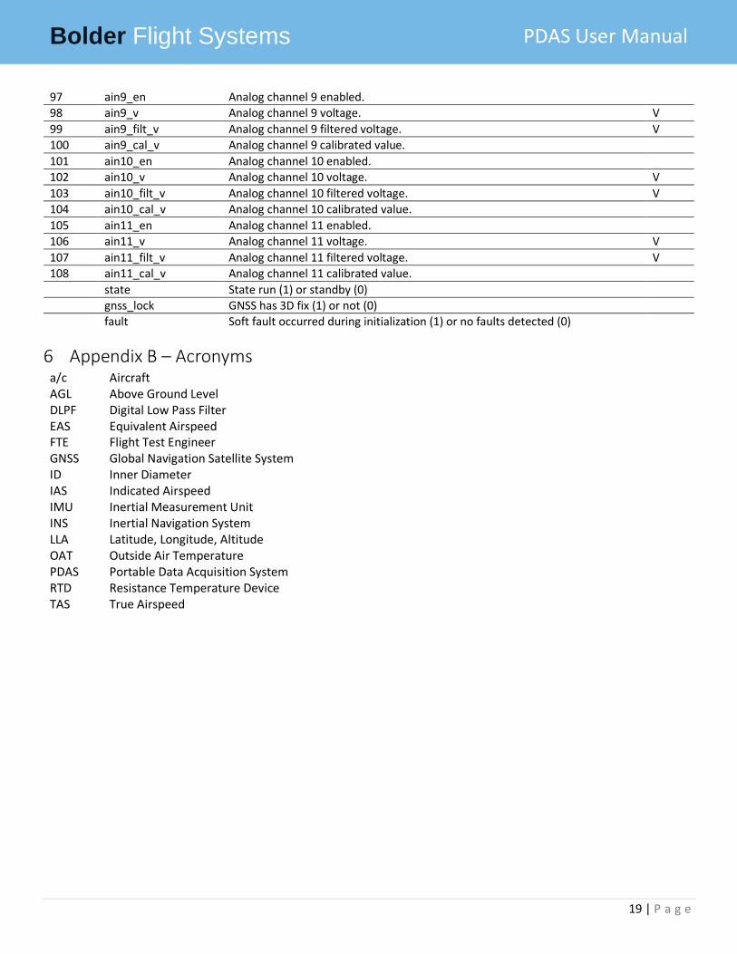
97 ain9_en Analog channel 9 enabled. 98 ain9_v Analog channel 9 voltage. V
99 ain9_filt_v Analog channel 9 filtered voltage. V
100 ain9_cal_v Analog channel 9 calibrated value.
101 ain10_en Analog channel 10 enabled.
102 ain10_v Analog channel 10 voltage. V
103 ain10_filt_v Analog channel 10 filtered voltage. V
104 ain10_cal_v Analog channel 10 calibrated value.
105 ain11_en Analog channel 11 enabled.
106 ain11_v Analog channel 11 voltage. V
107 ain11_filt_v Analog channel 11 filtered voltage. V 108 ain11_cal_v Analog channel 11 calibrated value.
state State run (1) or standby (0)
gnss_lock GNSS has 3D fix (1) or not (0)
fault Soft fault occurred during initialization (1) or no faults detected (0)
6 Appendix B – Acronyms a/c Aircraft AGL Above Ground Level DLPF Digital Low Pass Filter EAS Equivalent Airspeed FTE Flight Test Engineer GNSS Global Navigation Satellite System ID Inner Diameter IAS Indicated Airspeed IMU Inertial Measurement Unit INS Inertial Navigation System LLA Latitude, Longitude, Altitude OAT Outside Air Temperature PDAS Portable Data Acquisition System RTD Resistance Temperature Device TAS True Airspeed